

Page 1
McQuaY”
Operation and
Maintenance Data
Bulletin No. OM 112
March, 1993
FormNo. 573440Y
Absorption Chiller
NC-U Model
/
Page 2
NOTESTO USERS
1 . Before operating this chiller, YOUd-mid first thoroughly read this
manual.
You may not understand all of the explanations for operation when
you firstly read this booklet, however, P1ease strictly follow the
directions as shown hereinafter.
2.Besure not toleak theair into thechiller atany cases.
(Take care when YOUhandle the manual purge values and service
valves. )
3 . Do not turn off the main supply power to the chiller.
If turn off the breaker, purge unit of the chiller does not work.
4 . Operate chilled water ‘ pump(s) and air handling unit(s) during
dilution cycle operation of the chiller.
Chiller has a few cooling capcity during diluted cycle operation.
5. Specifications and eqipment may be changed as required by the
manufacture without any notice and obligation to the users.
814-6-0502-452-01
Page 3
OfIRATIYM4UK
CONTENTS
SKTION 1
i:;
1.3
1.4
SKI’ION 2
2.1
;::
2.4
2.5
Slxm 3
3.1
::;
::;
3.6
Page No.
NmEs’m
~ ~~~ ................................... ~
m HUtCm OF AKORPI’IoN “----------------------------------------2
COOL14MR4TlhGCYUE DHRIPHON ------------------------------20
MU.HVHE4’IIR lLUSIRATRIN -----------------------------------------25
= ~~ .................. .
CMRATION---------------------------------------------------------------------39
&iRATION80ARD ------------------------------------------------------------40
TEMHRATURESE1-TINe---"-"------------------------------------------------43
!3U-DIAGNG!XICSFUNCHON --------------------------------------------51
FRMRATIONFUUSTARTUP-----------------------------------------------54
OPIRATION---------------------------------------------------------------------58
~~ -----------------------------------------------------------------72
DALY m~ ---"----"--"--------------"------------------------------73
=~WT~ _ on -----------------------------------------80
WATIR‘lRE4TbHfI’-----------------------------------------------------------82
MAMH’UNCEm ~----------------------------------------------- 86
PARTSINWIETION------------------------------------------------------------89
m----------------------------------------------------------------
------................. .------- ------.-- ..-,.------.---- .........”.-., -.
“--“--”-------------------------------”-37
lMTNAMx-"-----------"--"------------"------"---"--"--------"75
I
i
ii
SiCHON 4
4.1
4.2
:::
4.5
~ -M ................................................ 9 ~
INDICATIONLAMP---------------------------------------------------92
Fmm
FAILURE---------------------------------------------------------------94
IN ‘IHECIXHJhKOHRATION-------------------------------------95
JN ‘lHE HE4TIIWCHRATION------------------------------------98
TIME ~-----------------------------------------------------------lOl
Page 4
WTKNI ENwlESUWTKN
mm 1 G13WRALDB3UPTION ---"----"---""-"---------"----"""-----"---"----""`----"-1
1.1 ‘lHE FRINCIPLEw ABSORITloN“-””-----”---”-”----:”---------”:-----”----2
WHYDOIB A HEATING(l-HI-L?---------------------------------------2
(1)
‘IHEFRINcm OF ABSCRFTIoN"-"-----"""---------"------"-----"----- 4
(2)
smJI ETEcr TYPE (BASIC CYuE) “----”””---””----””-----””--- 7
(3)
w - ~ .................................................... 8
(4)
CUOLINGWA~--------------------------------------------------------------9
(5)
VAURJM --"" ----" -"-----" "---" ---" -"---- "-"-" ""---" -----" ---" -----" "-----" ----lo
(6)
LRHJM EROMJDE(LB- :
(7)
~~ ~ ...............................................................l6
(8)
CONTENTS
Page No.
AKOREHW)--’--”---””----””----------”-ll
1.2 (x)oLINGCYuE DEStxlFrIoN -----------`"----"------"----"----"-"----------"lo
(~) ~~ - ..............................................................l9
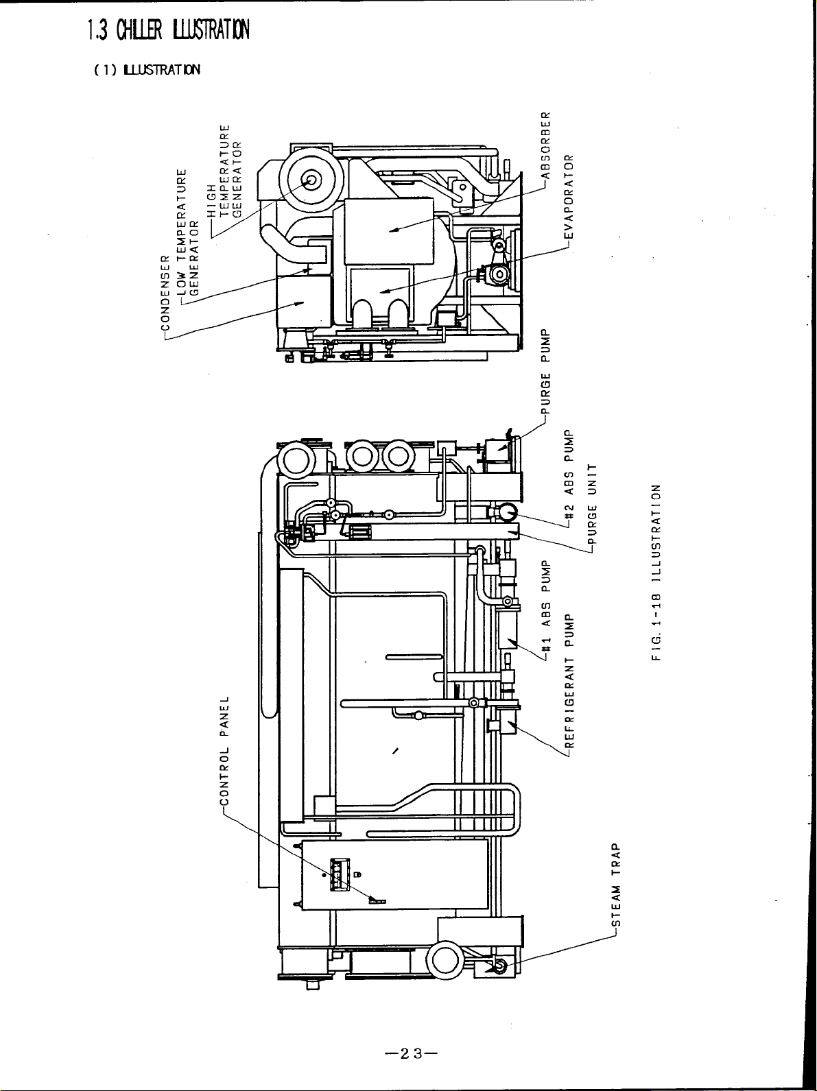
1.3 ~11.UR IUKIRATION --------------------------------------------------------23
(1) lUUSIRATION
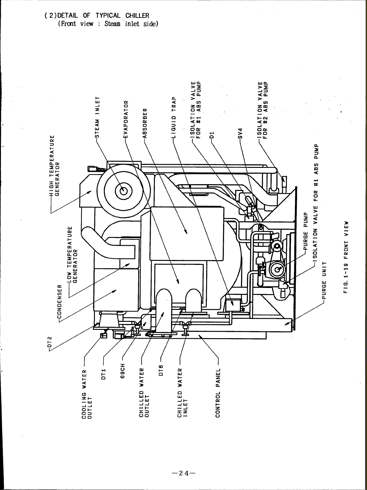
(2) ~A~ OF TYPIC4LU-IILLH?(m V~) ..........-....-.......24
(3) DETAROF TYPIC4LC1-HLUR(m VIEW)-----------------------25
(4) ~A~ ~ ~w ~~(R~ V~) ...........-...........26
(5) DETAITCF mm ~~(~ Vm) .......................27
(6) TYPBXL(DNIROLP~-------------------------------------------------28
(7) TYPEALm CONIROLVALVEANDm ~--.. ..... 30
(8) = ........................................................................3l
~.4 cJJqq’y ~~ .................................................................34
QIILI.EI WATIRANDU30UK WAIH------------------------------34
(1)
HIGHlXMPfRAllJREG134ERATOR---------------------------------------34
(2)
m-------" ""----"""--------"----"----------"-------""---------"-----"-"----""35
(3)
OITIIRS ----"----"-"----""-----""---"----"---""---------"""-"--""-"-"-"-----"-"-35
(4)
-----------------------------23
—l–
Page 5
1THE PRINCIPLEOFABSORPTION
(1)WHY
DOES A I-EATING CHILL ?
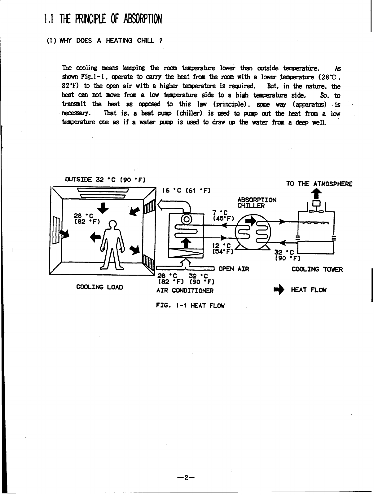
The cooling means keeping the room temperature lower than outside temperature. As
shown Fig.l-l, operate tocarry theheat from the room with alowert temperature (28C,
82 F) to the open air with a higher temperature isrequired.
heat can not move from low temperature side toahigh temperature side. So, to
transmit the heat as opposed to this law (principle), some way (apmratus) is
necessary.
temperature one asifawater pump isused todraw up the water from a deep well.
That is, aheat pump (chiller) isused topump out the heat from alow
But, in the nature, the
RE
COOLING LOAO
(82 “F) (90 ‘F]
AIR CONDITIONER
FIG. 1-1
HEAT FLOW
+
HEAT FLoW
–2–
Page 6
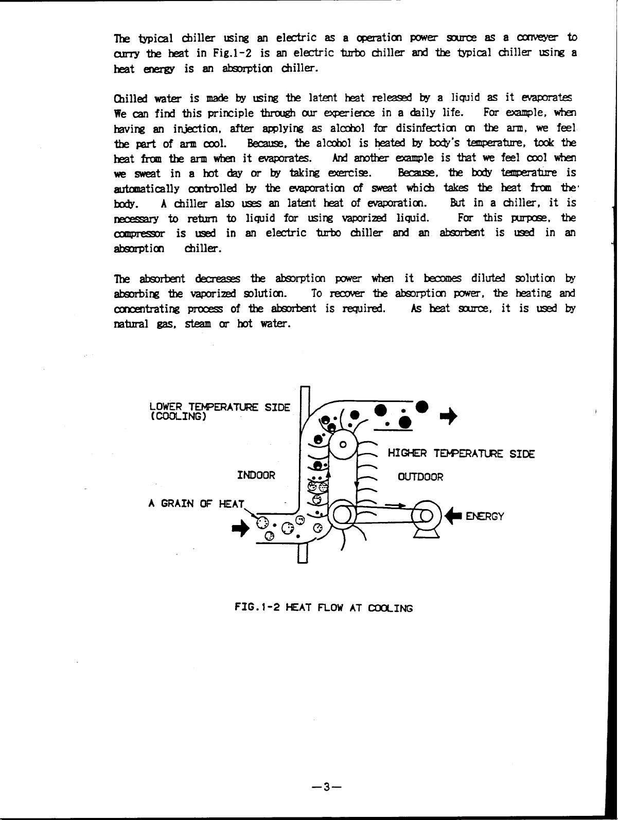
The typical chiller using an electric asa operation power source asaconveyerto
curry the heat inFig.1-2 is anelectric turbo chiller and the typical chiller using a
heat energy isanabsorption chiller.
chilled water is made by using the latent heat released by a liquid as it evaporates
We can find this principle through our experience in a daily life.
having an injection, after applying asalchol fordisinfection onthearm,wefeel
thepartofarm cool.
heat from thearm when itevaporates.
wesweat inahot day orbytaking exerxise.
automatically controlled by theevaporation ofsweat which takes theheat from the
body.
necessary toreturn to liquid for using vaporized liquid.
compressor isused in an electric turbo chiller and anabsorbent isused inan
absorption chiller.
The absorbent decreases the absorption power when itbecomes diluted solution by
absorbing thevaporized solution.
concentrating process ofthe absorbent isrequired.
natural gas, steam or hot water.
A chiller also uses anlatent heat ofevaporation.
Because, the alchol is heated by body’s temperature, took the
And another example is that we feelcool when
bercause, thebody temperature is
But in a chiller, it is
Toreceover theabsorption power, the heating and
Asheat source, itisused by
For example, when
For this purpose, the
INDOOR
A GRAIN OF HEAT=
FIG. 1-2
k!*%
-1=.
u
HEAT FLOW AT ~ING
HIGHER TEWERATU?E
smE
–3–
Page 7
(2) J-w PRINCIPLE OF ABSORPTION
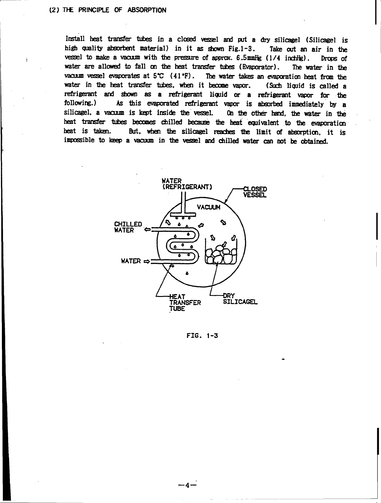
Install heat transfer tubes in a closed vessel and put a dry silicagel (Silicagel is
high quality absorbent material) in it as shown Fig.1 -3.
t
vesselto make avacuum with the pressure
of approx. 6.5mmHg (1/4 inchHg). Drops of
water are allowed to fall on the heat transfer tubes (Evaporator).
vacuum vessel evaporates at 5C (41F).
The water take anevaporation heat from the
water intheheat trasnfer tubes, when itbecome vapor.
Take out anairinthe
The water in the
(Such liquid is called a
refrigerant and shown as a refrigerant liquid or a refrigerant vapor for the
following.)
silicagel, a vacuum is kept inside the vessel.
As this evaporated refrigerant vapor is absorbed immediately by a
(Ontheother hand, thewater inthe
heat transfer tubes becomes chilled becasese the heat eqiovalent to the evaporation
heat is taken.
immpossibleto keep a vacuum
But, when the silicagel reaches the limit of absorption, it is
in the vessel and chilled water can not be obtained.
WATER
(REFRIGERANT)
CHILLED
WATER
MATER
e
*
6EA7
TRANSFER
TUBE
FIG. 1-3
+Y
SILICAGEL
—4–”
Page 8
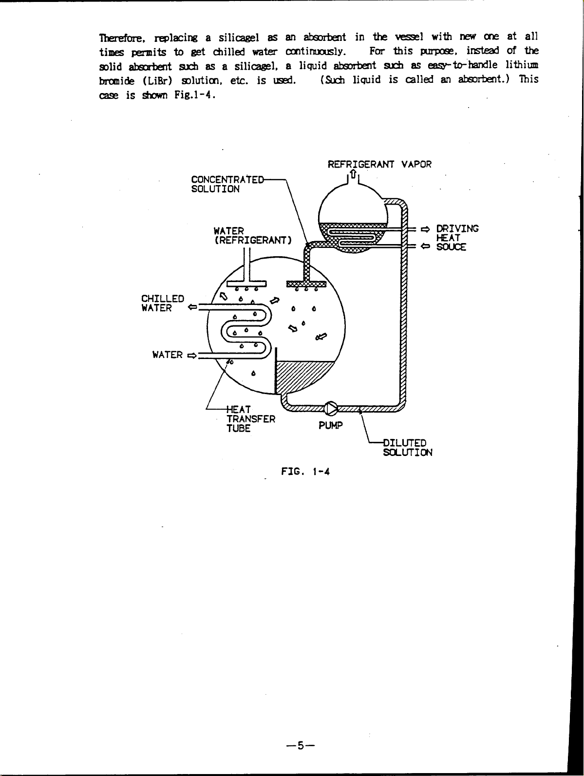
Therefore replacing a silicagel as an absorbent in the vessel with new one at all
times permits to get chilled water continuously.
For this purpose, instead of the
solid absorbent such as a silicagel, a liquid absorbent suchaseasy-to-handle lithium
bromide (LiBr) solution, etc. is used
(Such liquid is called an absorbent.) This
case is shown Fig.1-4.
CHILLED
WATER
WATER
CONCENTRATE
SOLUTION
L
EAT
TRANSFER
TUBE
REFRIGERANT
/
7
[
PUHP
bILUTED
VAPOR
S(MJTION
FIG. 1-4
–5–
Page 9

drops of LiBr solution areallowed tofall (Absorber) inside thevessel. The LiBr
solution absorbs refrigerant vapor.
But,when theabsorbent once absorbes the
refrigerant vapor, it is diluted and dereases ability to absorb. Resulting in the
chilled water can not be obtained.
I
in continuously. At this stage, thediluted solution is hinted by driving heat
This means that concentrated solution must befed
source (natural gas, steam or hot water:Generator). The heat causes the solution to
release the absorbed refrigerant and also
reconcentrates thesolution.
The refrigerant vapor which is released from the solution when heated,
separate vessel (Condenser) liquid refrigerant. Drops of
again introduced into the vacuum vessel andrecycled
This is shown
is cooled in a
this. water are.
Fig.1-5. ‘
FIG. 1-5
–6–
Page 10
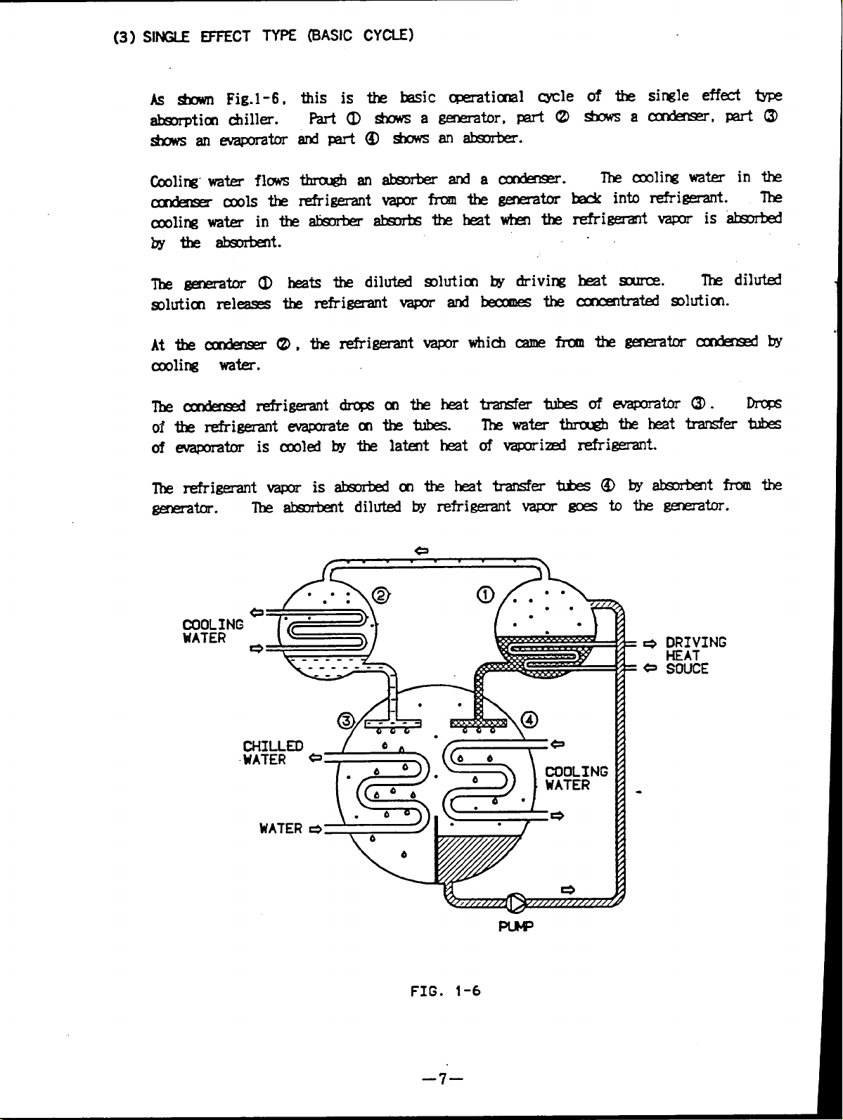
(3) SINGLE EFFECT TYPE (BASIC CYCLE)
Asshown Fig.1-6,
absorption chiller.
this is the basic operational cycle
Part (l)shows agenerator,
shows anevaporator
Cooling water flows
condensor cools the
cooling water intheabsorber absorbs the heat when the
bythe absorbent.
The generator (1)heats the diluted solution bydriving
solution releases the refrigerant vapor and becomes the
transfers tubes ofevaporator (3). Drops
The water through the heat transfer tubes
ofvaporized refrigerant.
of the single effect type
sbows acondenser, part (3)
The cooling water in the
back into refrigerant. The
regrigerant vapor is absorbed
heat source.
The diluted
concentrated solution.
COOLING
WATER
CHILLEO
WATER
WATER
----- .-
DRIVING
HEAT
SOUCE
FIG. 1-6
–7–
Page 11
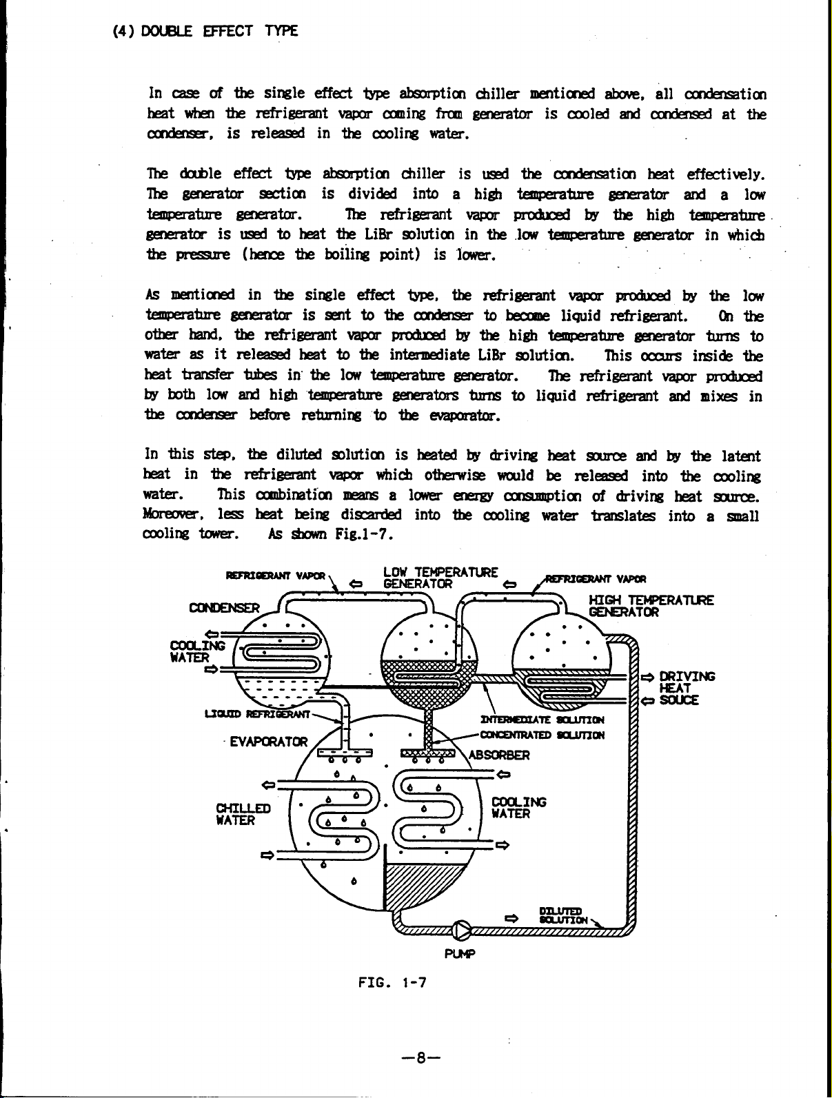
(4) DOUBLE EFFECT TYPE
In case of the single effect type absorption chiiller mentioned above, all condensation
heat whn the refrigerant vapors coming from generator iscooled and condensed atthe
condensor, is released in the cooling water.
The double effect type absorption chiller is used
The generator section is divided into a high
-- generator.
generator is used to heat the LiBr solution in the
the pressure (hence the boiling point) is lower.
As mentioned in the single effect type, the refrigerant vapor produced by the low
temperature generator issent tothecondensor
other hand, therefrigerant vapor produced bythehigh temperature generator turns to
water as it released heat to the intermediate LiBr solution.
heat transfer tubes in the low temperature generator.
byboth low and high temperature generators turns to liquid refrigerant and mixes in
thecondenser before returning totheevaporator.
In this step, the diluted solution is heated by driving heat source and by the latent
heat in the refrigerat vapor which otherwise would be released into the cooling
water.
Moreover, less heat being discarded into the cooling water translates into a snail
cooling tower.
This combination means a lower energy consumption of driving heat source.
As shown Fig.1-7.
The refrigerant vapor
the condensation heat effectively.
temperature generator and alow
produced by thehigh temperature
low temperature generator in which
to become liquid refrigerant. On the
This occurs inside the
The refiigerant vapor produced
.
I
FIG. 1-7
–8–
Page 12
(5) COOLING WATER
lo
The lower temperature of cooling water
a)
The absorption power ofLiBr solution isstrong atthe lower temperature ofthe
cooling water.
condensed temperature ofregrigerant downs.
low.
As the boiling temperature (generator temperature) oftheLiBr solution downs
when thecondensed pressure islow,
When thetemperature ofcooling water in thecondenser is
Therefore condensed pressure becomes
calolific value of driving heat source can
decrease. This means save energy.
It is not acceptable
b)
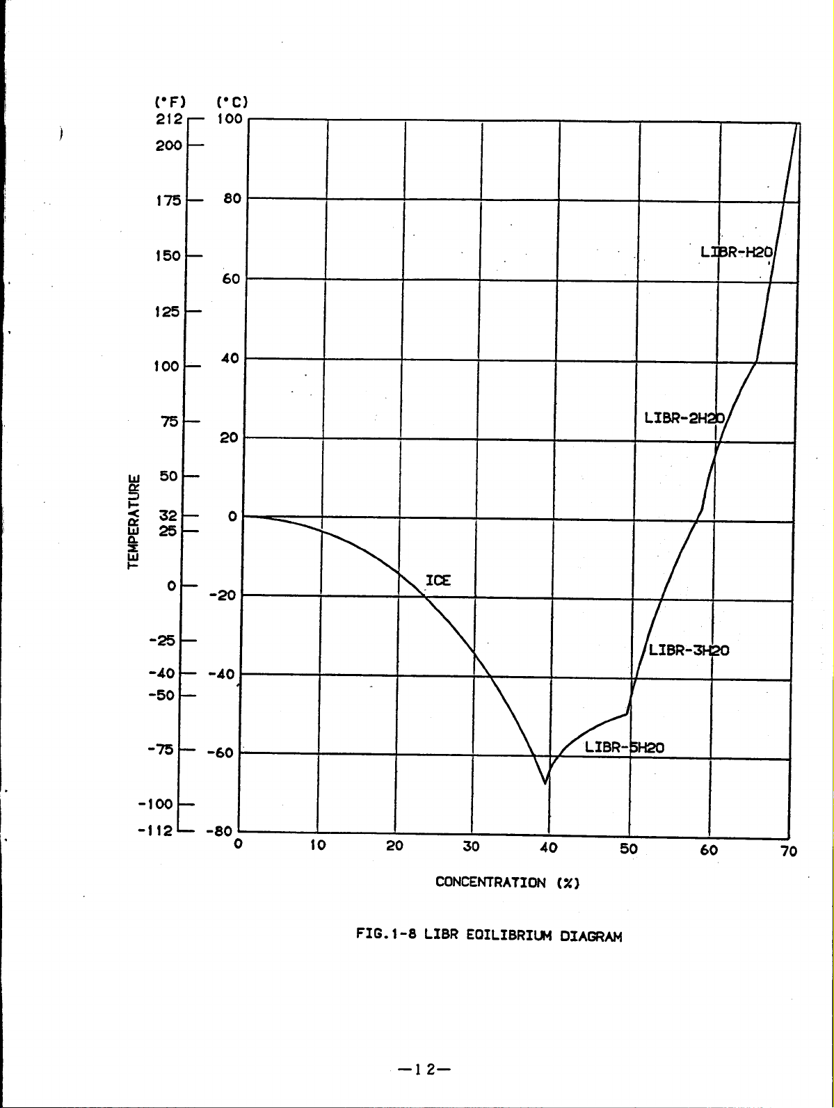
As shown Fig.1-8, a
LiBr solution of
temperature For
that the temperature of cooling water is too low.
few LiBr dissolves with water at low temperature.
That is, the
high concentration becomes crystallization under the lower
example, it is crystallized with concentration of 65% at the
temperature lower then 42C (108F), with concentration of 60% at the temperature
lower than 17C (63F).
Chiller has some problems when cooling water temperature becomes too high
c)
When thetemperature of thecooling water becomes tohigh, theabsorption power of the
LiBr solution decreases.
temperature and wastes much fuel.
The chiller can not get the normal chiller water
Therefore, to prevent this, the maintenance for
cooling water SYStem (epuipment and control) and water treatment are required.
d)
Water treatment of cooing water
The water treatment of the cooling water is an inportant factor for the chiller. If
thewater quality isno good, scale adheres totheinside ofthe heat transfer tubes,
resulting in the
decreases transfer heat effect and waste fuel. Astheheat transfer
tubes may become corroded, itisrequired to fully take care ofthe water treatment.
–9–
\
Page 13
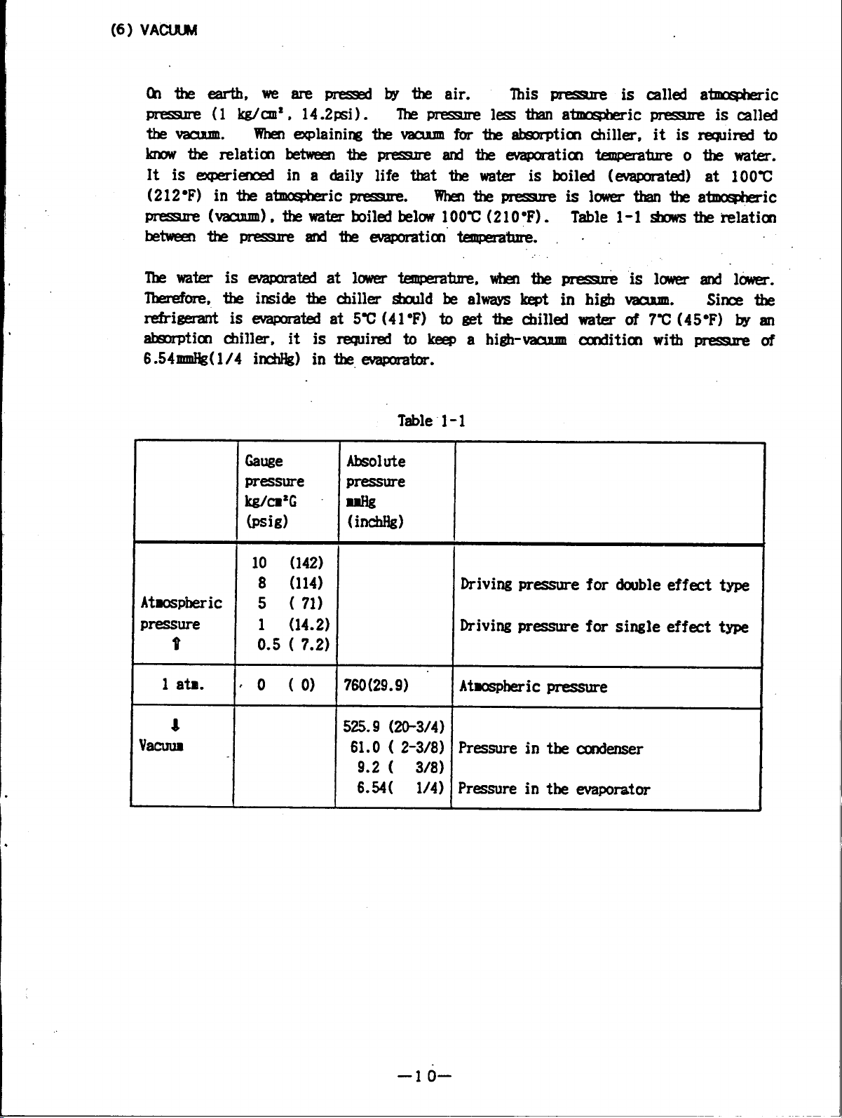
(6) VACUUM
Onthe earth, wearepressed bythe air.
pressure (1kg/cm, 14.2psi).
the vacuum.
When explaining the vacuum for the absorption chiller, it is required to
This pressure is called atmospheric
The pressure less than atmospheric pressure
is called
know the relation between the pressure and the evaporation pressure o the water.
lt is experienced in a daily life that the water is boiled (evaporated) at 100C
(212F) in the atmospheric pressure.
When the pressure
pressure (vacuum), the water boiled below 100C (21OF).
between the pressure and the evaporation temperature.
.
is lower than the atmosheric
Table 1-1 shows the relation
The water isevaporated atlower temperature, when thepressure is lower and lower.
Therefore, the inside the chiller should be always kept in high vacuum.
Since the
refrigerant is evaporated at 5C (41F) to get the chilled water of 7C (45F) by an
absorption chiller, it is required to keep a high-vacuum condition with pressure
of
6.54mmHg (1/4 inchHg) in the evaporator.
Table 1-1
Gauge Absolute
pressure
W“2G
m=me
*
(psig)
Atmospheric
pressure
t 0.5 ( 7.2)
1 ata.
{o (o) 760(29.9)
4
vacullB
(inch&)
10 (142)
8 (114)
Driving pressure for double effect type
5 ( 71)
1 (14.2) Driving pressure for single effect type
Atmospheric pressure
525.9 (20-3/4)
61.0 ( 2-3/8)
Pressure in the cmdenser
9.2 ( 3/8)
6.54( 1/4)
Pressure in the evajxmtor
–lo–
Page 14
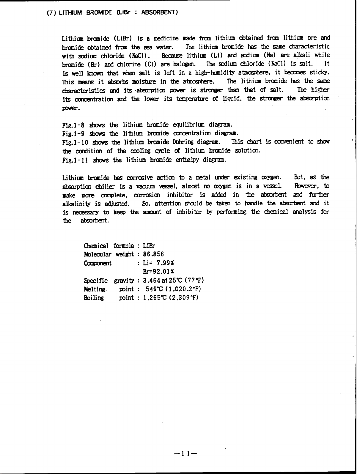
(7) LITHIUM BROMIDE (LiBf : ABSORBENT)
Lithium bromide (LiBr) isamedicine made from lithium obtained fromlithium ore and
bromide obtained from theseawater.
with sodium chloride (NaCl).
Because lithium (Li) and sodium (Na) are alkali while
bromide (Br) and chloride (Cl) are halgen.
The lithium bromide has the same characteristic
The sodium chloride (NaCl) is salt. It
is well known that when salt is left in a high-humidity atmosphere, it becomes sticky.
This means itabsorbs moisture intheatmosphere.
The lithium bromide has the same
characteristics and its absorption power is stronger than that ofsalt.
its concentration and the lower its temperature of liquid. thestronger the absorption
power.
The higher
Fig.1-8 shows the lithium bromide
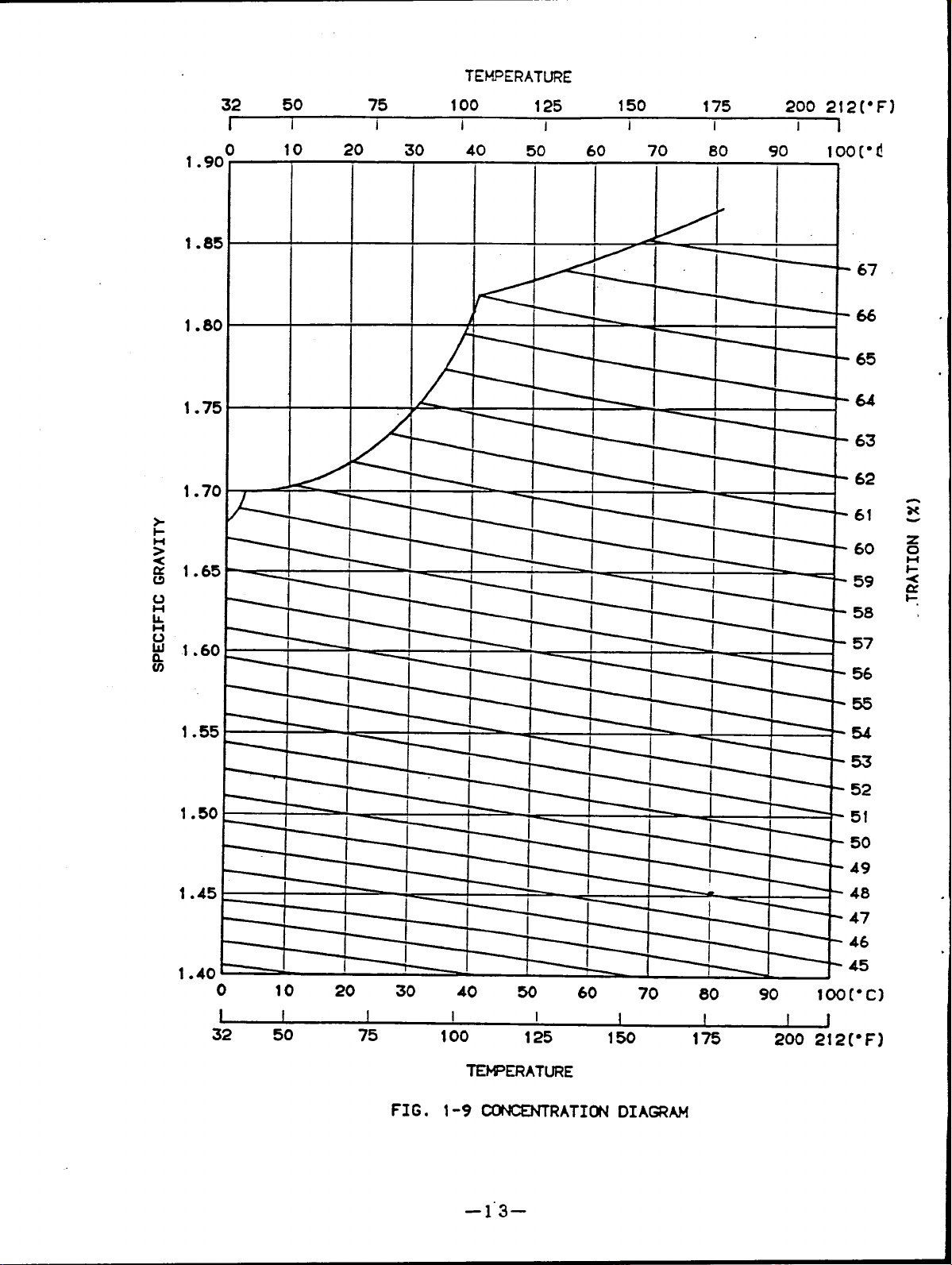
Fig.1-9 shows the lithium bromide
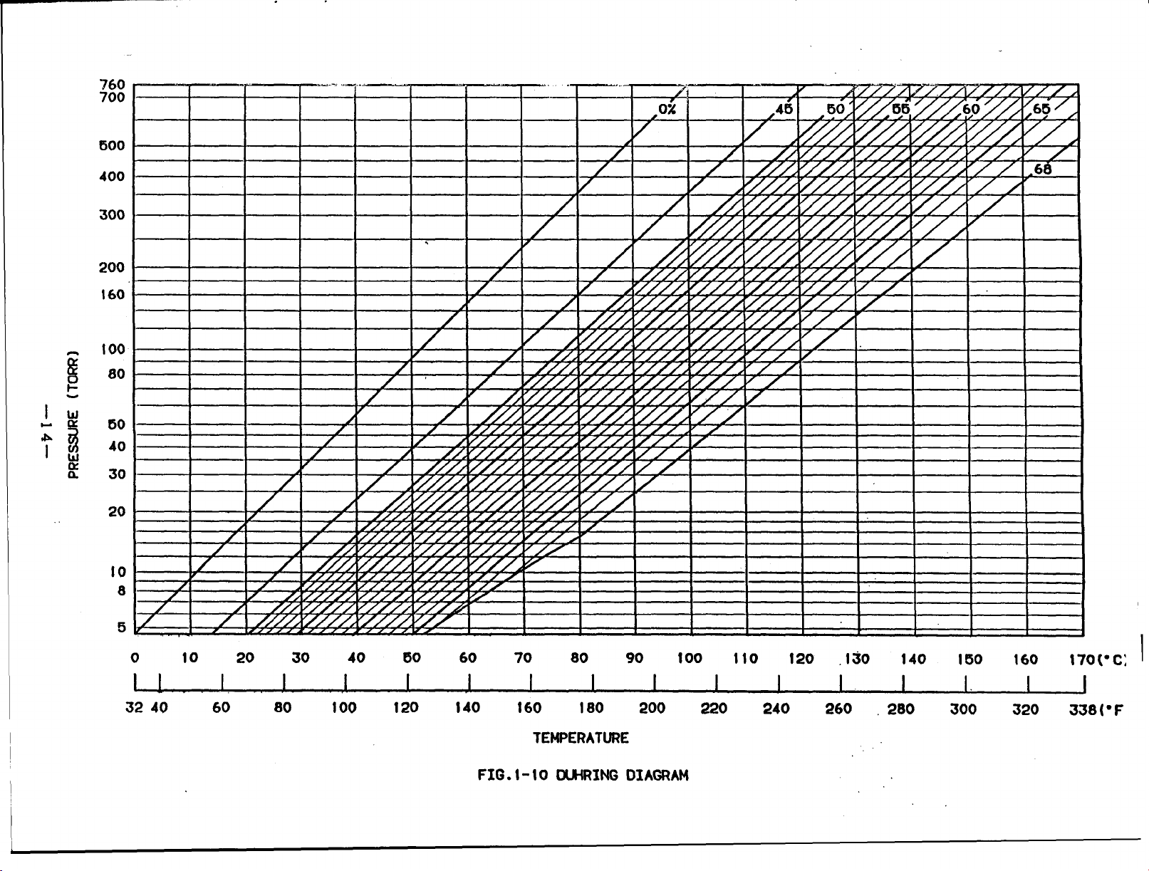
Fig.1-10 shows the lithium bromide
the condition of the cooling cycle
equilibrium diagram.
concentration diagram.
during diagram.
This chart is convenient to show “
of lithium bromide solution.
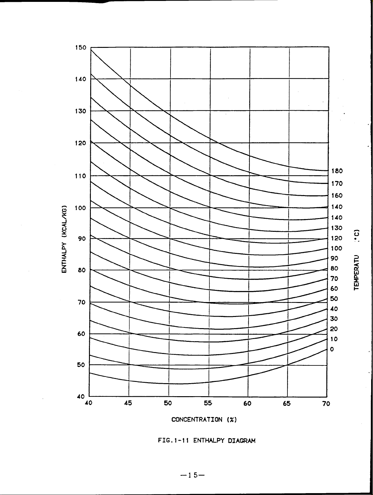
Fig.1-l1 shows the lithium bromide enthalpy diagram.
Lithium bromide has corrosive action to a metal under existing oxygen
But, asthe
absorption chiller is a vacuum vessel, almost no oxygen is in a vessel. However, to
make more complete, corrision inhibitor is added in the absorbent and further
alkalinity is adjusted.
So, attention should be taken to handle the absorbent and it
is neccessary to keep the amount of inhibitor bY performing thechemical analysis for
theabsorbent.
Chemical formula : LiBr
molecular weight : 86.856
Component
: Li= 7.99%
Br=92.OI%
specific gravity : 3.464 at25C (77°F)
Meltingr
point :
549C. (1 ,020 .2F)
Boiling point : 1.265C (2,309F)
–1 l–
Page 15
21
20
12!
100
80
L:
60
10(
-25
-40
-50
-75
40
LX5R-21+2
20
.
.
0
.
.
c
-40
-60
I
-1oo
-80
0
10
20
30
CONCENTRATI~ (%)
EOILIBRIUM DIAGRAM
40
50
60
70
I
Page 16
TEk!.!ERATURE
32 50 75
I
1.9C
1.85
1.8C
1.75
1.70
1.65
I
10 20 30 40 50 60 70 80 90
100
I
I
125
I
150
I
175 200
i
I
—
—.-.
t
100[”(!
63
62
61
60
59
67
.
x
.
1.60
1.55
1.50’
1.45
1.40
o
1
32 50
J
I
---r--t-”
I
—
I
I
3=1
10 20 30 40 w 60 70 80 go
I
75
1
I I
100
TEMPERATURE
125
I
150
I
175
100[’C)
I
J
200 212[”F)
58
57
56
55
54
52
51
50
49
48
FIG.
1-9 CONCENTRATI~
–1”3–
Page 17
760
700
600
400
300
200
160
100
80
u
60
40
30
20
10
8
5
o
I
3240 60 80 100 120 140
10 20 30 40 60 60 70 80 90
I 1, 1 1
I
I
FIG. t-10 DUHRING DIAGRAM
I
160
TEMPERATURE
180 200
1
100
I
220
110
I
120
I
240
260
.130
1.
140
I 1.
280 300 320
I 50
160
170(” C:
I
I
338(” F
I
Page 18
150
\
140
130
120
110
- 160
.
100
60
50
40
90
80
70
40
-l
45
~ 130
%!
—
I I
I I ---
(
—
120
70
60
50
40
30
20
10
0
50
55
60
65
70
CONCENTRATION (%)
FIG.1-11 ENTMU_PY DIAGRAM
–15–
Page 19
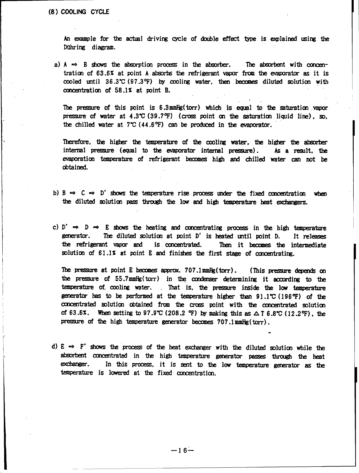
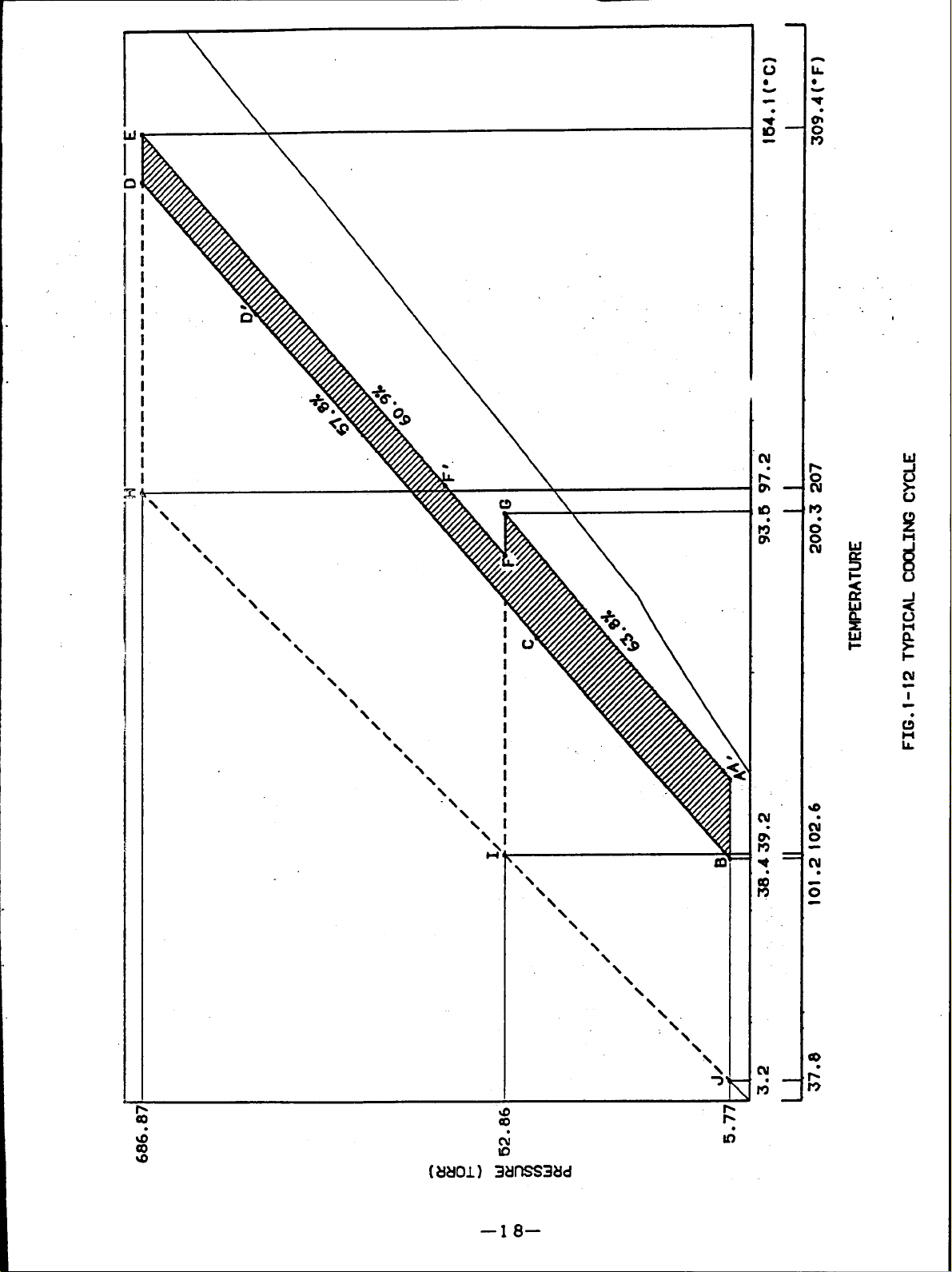
(8) COOLING CYCLE
An example for the actual driving cycle of double effect
Duhring diagram.
a) A-B shows theabsorption process in theabsorber.
tration of 63.62 at point A absorbs the refrigerant vapor
cooled until 36.3C (97.3F) by cooing water, then becomes diluted solution with
concentration of 58.1% at point B.
The pressure of this point is 6.3mnHg(torr) which is equal to the saturation vapor
pressure of water at 4.3C (39.7F) (cross point on the saturation liquid line), so,
the chilled water at 7C (44.6F) can be produced in the evaporator.
Therefore, the higher the temperature of thecooling water, thehigher the absorber
internal pressure
evaporation
obtained.
b) B- C-
the diluted
temperature ofrefrigerant becomes high and chilled water can not be
D' shows the temperature rise process under the fixed concentration when
solution pass through the low and high temperature heat exchangers.
(equal to the evaporator internal pressure .
type is explained using the
The absorbent with concen-
from the evaporator asitis
)
As a result, the
generator
the refrigerant vapor and is concentrated.
solution of 61.1% at point E and finishes the first stage of concentrating.
The pressure atpoint Ebecomes approx. 707.1mmHg(torr).
the pressure of 55.7mmHg(torr) in the condenser
temperature ofcooling water. That is,thepressure
generator has to be performed at the temperature higher than 91.1C (196F) of the
concentrated solution obtained from the cross point with the concentrated solution
of 63.6%.
pressure of the high temperature generator becomes 707.mmHg (torr).
I
The diluted solution at point D’ is healed until point D.
Then it becomes the intermediate
(This pressure depends on
determining it according to the
inside the low temperature
Whensetting to 97.9C (208.2F) bymaking this as^ 6.8C (12.2F), the
It releases
—16-
Page 20
F-F-G shows theconcentrating process in thelow
temper
e)
absorbent with 61.1% atpoint F'isheated bythe refrigerant vapor from the
temperature generator.
concentration rises, and it becomes theconcentrated solution of63.6%. Thus, the
second stage oftheconcentration isfinished.
The pressure atpoint Gisdetermined bythe temperature ofthe cooing water. With
thecondensation temperature of40.2C (104.4F) thepressure
pressure ofthis temperature, 55.7mmHg (torr).
G-A’shows theprocess ofthe heat exchanger with the diluted solution while the
f)
concentrated solution goes out from low temperature generator and passes through the
As a result, the refrigerant vapor isgenerated, the
isthesaturated vapor
g)
Asdescribed above, itcanbeunderstood that the cycle of the absorption cooling
system depends onthe
taking out temperature
temperature condition (partially determination element from the
of the chilled water).
theabsorber and iscooled bythe
starts toabsorb therefrigerant
–17–
Page 21
d
\
\
\
\
\
\
\
\
\
“\
\
\
\
\
\
\
-\
\
\
\
\
-\
\
\
\
\
\
\
\
\
\
\
\.
.\
\
u
a
.
\
i
:
\
\
;
\
.
I
m
.
&
H
h.
I
3tJf7SS3Ud
–18–
Page 22
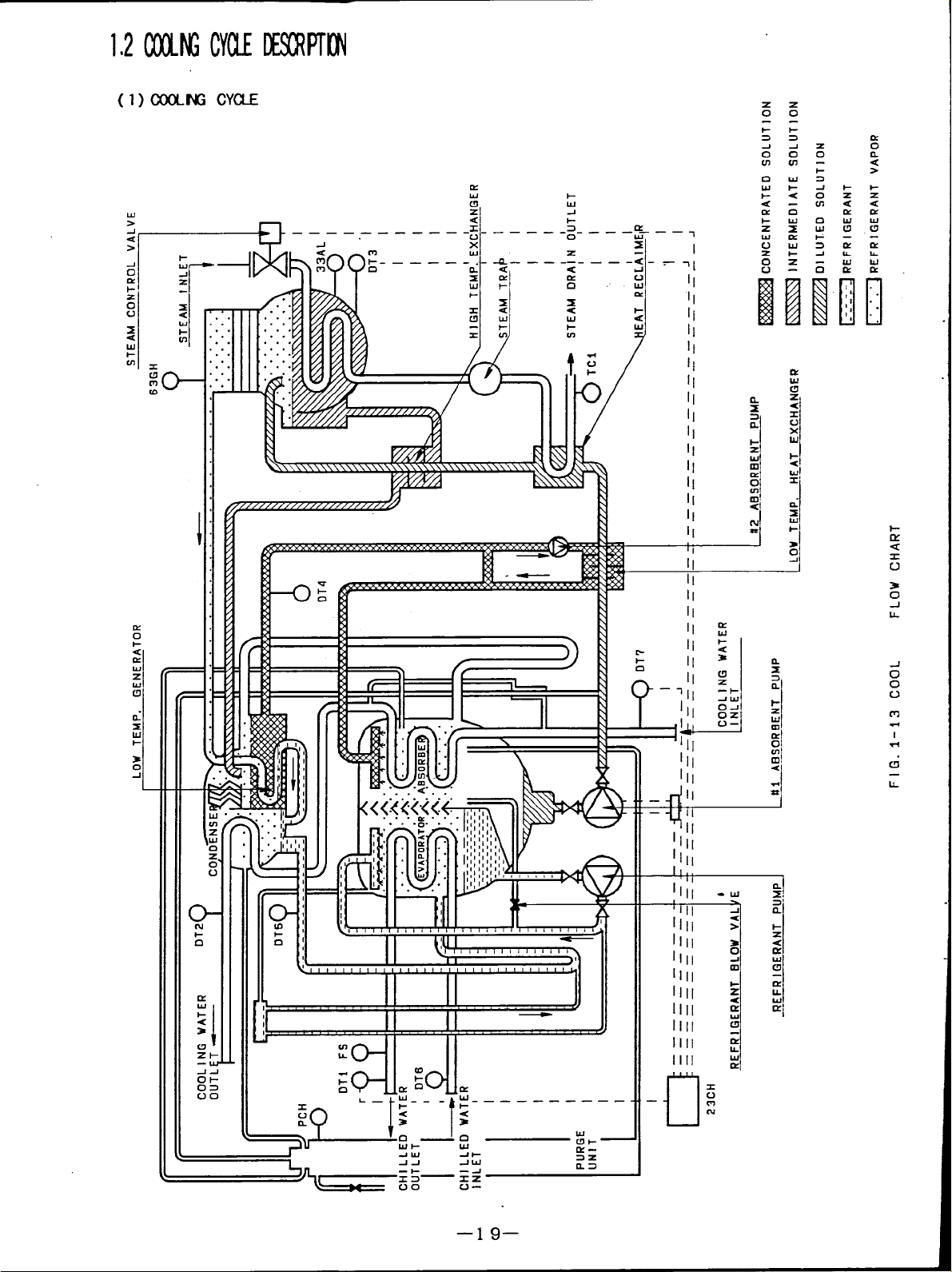
1$2(XIMGcm DEsowTnt”l
(l) COOLNG CYUE
K
IA.J
!&---+ i--------i------$----%--:
1-
w—
-1
z
.-1.
1-
-r
1LtY
t :
z
0
‘5
z
0
:
07
u
1-
Z
a
w
w
(5
El
II
[1
[
d
-d
1!1
i
o
0
Q-
1-
-w
-IA
ol03
00
11 [3!,, I,!!,,,,,!!< Ii II :
o-l
L
e
0
II II
—
——— ——— ———
c1
&
C!Y
L
II
II
II
lilt
111[
1111
1111
1111
—
I
—19—
Page 23
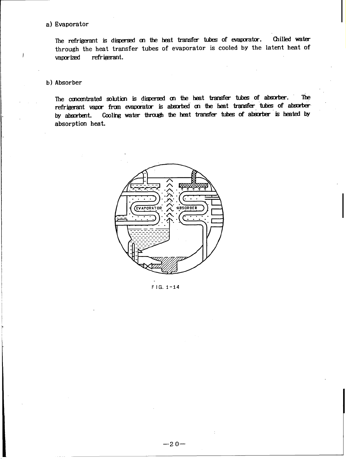
a) Evaporator
The refrigerant isdispersed onthe heat transfer tubes ofevaporator.
Chilled water
through the heat transfer tubes of evaporator is cooled by the latent heat of
J
vaporized
b) Absorber
refrigerant.
FIG. I-14
—2 o—
Page 24
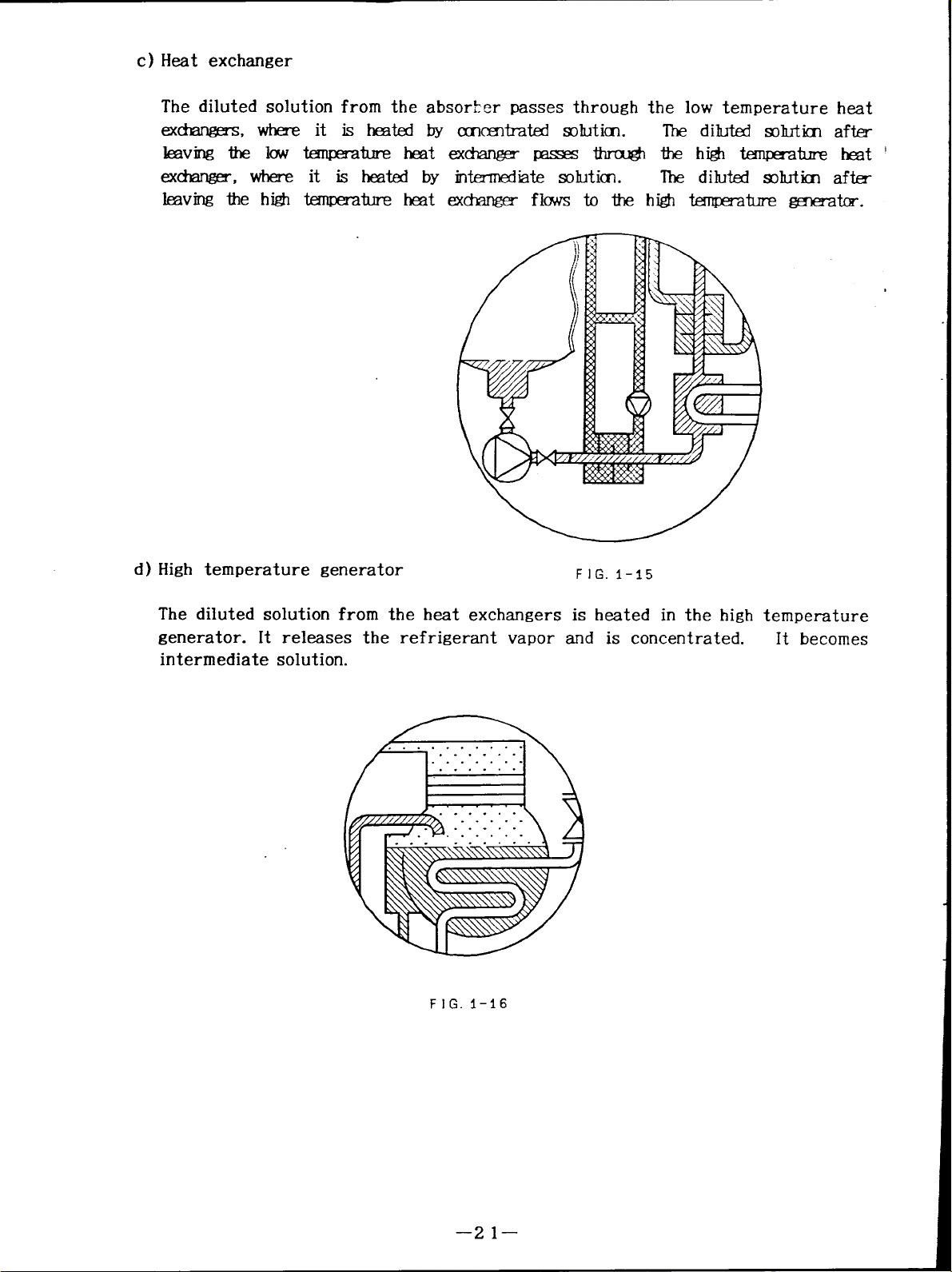
c) Heat exchanger
The diluted solution from the absor$er passes through the low temperature heat
exchangerss, where it is heated by concentrated solution.
The diluted solution after
leaving the low temperature heat exchanger passes through thehigh temperature heat
exchanger, where it is heated by intermdiate solution.
The diluted solution after
leaving the high temperature heat exchanger flows to the high temperature generator.
d ) High temperature generator
FIG. I-15
The diluted solution from the heat exchangers is heated in the high temperature
generator. It releases the refrigerant vapor
and is concentrated.
It becomes
intermediate solution.
FIG. 1-16
—21—
Page 25
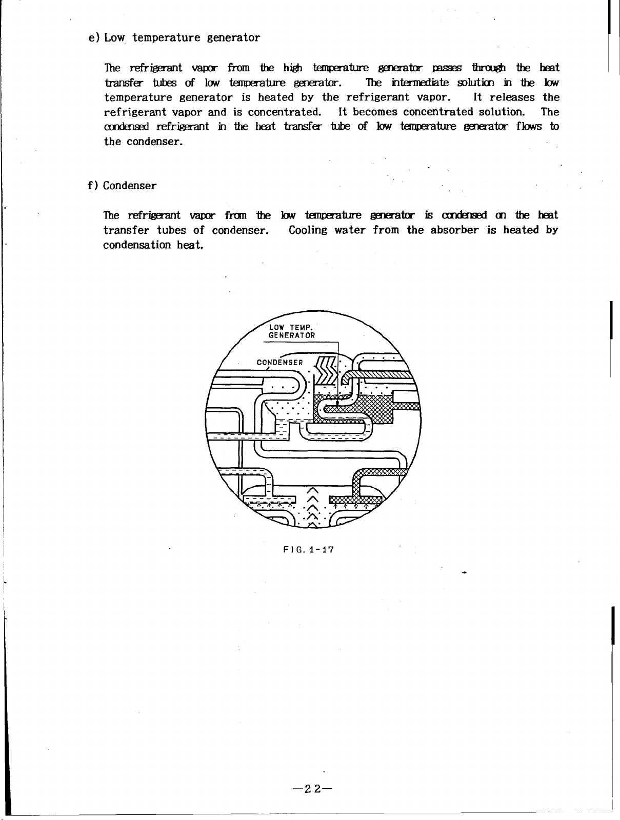
e) Low temperature generator
The refrigerant vapor from thehigh temperature generator passes through theheat
transfer tubes oflowtemperature generator.
The intermediate solution in the low
temperature generator is heated by the refrigerant vapor.
refrigerant vapor and is concentrated.
It becomes concentrated solution. The
condensed refrigerant intheheat transfer tube oflow temperature generator flows to
the condenser.
f)
Condenser
It releases the
The refrigerant vapor from thelowtemperature
transfer tubes of condenser.
Cooling water
condensation heat.
generator iscondensed ofthe heat
from the absorber is heated by
FIG. 1-17
—22–
Page 26
103MIERlMRATl$i
(l) UlJSTRATI14
w
CY
9’ 2.1
‘L=’
w
m
12
0
n
<
>
w
w
i-
-1
w
z
<
L
-1
0
CK
1-
Z
0
c-l
k
I
II I
II
w’
111
I
-1
-1
m
l-!
t
w
IL
u
I
D----r&”#--”
—23–
Page 27
( 2 )DETAIL OF TYPICAL
(Fret view :
Steam
1-
CHILLER
inlet side)
%%
-lx
an
>
:“
u
1-
Zm
oa
U-J
II \ \
1-
I
u
m
z
w
n
0/
UJ
IL
.
\
-1
:
<
n
a
Z*
—w
-I-I
ol-
03
00
0
wt-
-lW
-l_l
-t- --l
X3
00
0
W
-ii-
-lW
X2
cl-
–24–
Page 28

(3) IHAL OF TYPCALW-1%?
(Rmr Viw
: ham Wtlet Skk)
cl
w
Ix
0
-1
0
w-l
l-w
Zz
oa
c-la
3
C5
z
.-
w
w
m
1
w
1-
x
cl
x
\/’
// t---
>
1, 1 *
N
C!i
I.L
\
\
wl-
I-3
ma
–2 5–
I--J
<u
Ww
XCE
-I
Page 29

2
DT4
l-uul~
hlhl
i I-!w .
/
1111L\
Ill LDl / \\
\/
‘ISOLATION VALVE
FOR #2 ABS PUMP
[
PURGE PUMP
SV9
// \\
HEAT EXCHANGER
\
ISOLATION VALVE
FOR 81 ABS PUMP
II
\
‘ISOLATION ‘VALVE
FOR REF PUMP
\ ~,~~ ~,”~
IL
//
I Phil
\
\ \
\’
“kSV6 \
STEAM TRAP
1“
FIG. I-21 RIGHT VIEW
Page 30

.+
;U
mn
U.in
>X
-10
<n
>
Zm
0<
I-*
us
J
Oiz
ma
x
m
Wn
>Z
-la
<n
>
m
zm
oa
l-+
4#
-J
Otx
O-Jo
IL
cum
>>
(’U+
>>+
mm>
kii$kwmm+dll
/
\
\
1
7-
/
/
/
\
3
w
m
>
‘L--
-1
Ill
z
/
/
, , ,
/
>
Cr
u
1IL
w
A
l-u
ru
1
*
cl
IL
‘r
u
—2 7–
Page 31

(6) TYPCI CCNllW_ PKL
IndiCatiOn LAMP
OPERATION BOARD
EMERGENCY
STOP SWITCH
/’
,,
II
FIT. I-23 CONTROL PANEL
CONTROL PANEL
HIGH VOLTAGE
FIELD WIRING OPENING
/
CONTROL CIRCUIT
FIELD WIRING OPENING
—28—
Page 32

,,,CONTROL EOARD
,“
/’
/
/(’I
/
,1
,,
.
/
,coNTROL RELAY
.-
, FAN MOTOP
MODE SELECT SWITCH UNIT
I /’ 1,
I
/
II u“
POTENTIOMETER
/“””
/“’’FusEs
FUSE HOLDERS
TERMINAL BLOCK
~ CONTROL TRANSFORMER
POWER TRANSFORL’ER
INVERTER
/---’-’ ‘EACT”R
CIRCUIT BREAKER
/’”
WIRE CHANNELS
II -—H————H——+
lu-
FIG. 1-24 INSIDE OF CONTROL PANEL
1 ABSORBENT PUMP
NO.
MAGNETIC CONTACTOR
\
~ MAGNETIC CONTACTOR
)
i
~ REFRIGERANT PUMP
b
i
~ PURGE PUMP
)
)
i
~TERMINAL BLOCKS ,
NO.2 ABSORBENT PUMP
MAGNETIC CONTACTOR
MAGNETIC CONTACTOR
CONTROL CIRCUIT
MOTOR TERMINAL BLOCK
r
P
HIGH VOLTAGE
FIELD
INTERNAL WIRING
CONTROL CIRCUIT
FIELD WIRING TERMINAL BLOCK
WIRING TERMINAL BLOCK
—2 9–
Page 33

(7)nPmlS TEAMCwlRclv ALvE/ww EAM TRAP
REDUCI N
G
iPOSITION R
STEAM 1 LET
Y
FIG. 1-25 STEAM TRAP(PNEUMATIC TYPE)
‘-i=+’
STEAM OUTLET
/-
DRAIN INLET DRAIN OUTLET
F}G. I-26 STEAM TRAP
—3 o—
Page 34

(8) SYR430L
a)b)Chiller construction
symbol Name
EVA
ABS
COND
HT.GENE
HT.REC
LT.GENE
HT.EX High. ~tum kit exchanger
LT.EX w tanperatm? bet exchanger
#l AESKJMP No.1 Akrilmt llllnp
#2 AESKJMP
REF PUMP
Temperatum senmr
~tor
Hmt reclaim7-
Law tmlpe?atum genelatm
NO.2 Aknrbent Lump
——
Refr&ant pmlp
SY-mM
DT1
DT2
DT3
DT4
DT5
DT6
DT7
Name
Chilled water outlet
Ccoling water cutlet
High &mpe&mz generator
Low temrecatlm fmet-ator
.———
— —.
Chilled water inlet
Cooling water cutlet
Location
Chilled water outlet pipe
before flange.
cooling water
cutlet me
before flange.
%dc
Si& of high ~k
generator.
Intermediate fmlutim pipe of
LT.GENE outlet.
—.—
Refrke=mt pipe of ~
outlet.
Chilled water inlet pipe
kfm flange
Cooling water inlet pipe
before flange.
–31–
Page 35

symbol Name
Location
23CH
TC1 Strom dTain tmpemtum
El ,E2 ,E3 GmeAOr wlutim level
33AL Genmitor duticn level
63GH Gena’atm- DFslJR
69CH (Xilled wakr fkw Witch
PCH Palladium cell heater
I SYmM
V1
I
V2
Electronic controller
electrod
UXltrol” M swim
I
I No.2 m valve
Name
mvitrh Near b solutim Mel box
Inchxkd opemtim bc9rd
Skam dram outlet pipe
beklm flan@
Solution level box beside the
high temperature ~ti
In the control panel “
Chilled water outlet pipe
Topcnthe~ tank
I
Location
Besick themtank
p?si(ktheml%etadc
I
V3
V4
Refrigerant blow valve
I
IBesdethelxlrgetark
Evaporatm Sirk?
I
I
—32—
Page 36

e) Service valve
&mhol
Name
Svl Service mlve for maintmane
SV2
&nice wlve for manomk
SV3 *ice valve for refr~t
SV4 servi~ wdve for diluted
solution
SV5 &nice valve for rnternkxiiate
solution
SV6 Sewim mlve fw cmcmtrated
solution
SW
Service valve for gemator
~-
SV8
Setvice valve for ~tor
maintenance
SV9 !krvim valve for hczit
ex-
Imintmance
Location
E?eskk?themiank
Besi&t&lxJnge tank
(xl the refrigerant pip!?
I’karthe No.lalKr<lxmlp
(Outkt
PiPe of xl AK FuMP)
kskk the high tenzxzati
heat cX-
&si&thebw*ture
kat ex&arw-
On the solution level box
I?ottanofthehigh_k
-*
kick of high tmpczature
bt mknger’s I-Ezl&
f)
Sight glass
g)
F
Svl 1
Symbol
D1
D2
D3
ml
xl
Servi@ valve for @lladium
Tcx)the~tank
cell
Name
I.kunwr for dilukl mluticn
Location
outlet pipeof#l A5s FuMP
afk - valve
IMnPer for intermediate
solution
IkxnP=- fcr cxlncmt?akll
solution
Name
MeTIIEdiate dltim pipe
betwem HTE4 and LTGENE
Gncmtrated Solutial pti
betwem LTJ23W and LTEX
Location
sight glass fcr reil-igerant Ikskk eVam&or
level
—33–
Page 37

114SAFETYElm
(l) CHLLED WATER AN) COOLNG WATER
No Item
I
Setting point Alarm indication
1 Ink-lock of chilkd water pmnp
2 Interlock of Cmling water m
3 Fw flow rate of chilkxl wak
4 Gilled wak- fmzz IX-&Aim
(LAYw-cutof chilled wati cutlet knp.)
5 Low-cut of mling water inlet kmpemti
(2) HGli TEWERATLRE GEMRATOR
No
High-d of ~tor tempemtum(boling) 165°C (329”F)
6
Item
Indication lamp.
Indication lamp
50 %
2.5°C (36.5”F)
19”C (66.2”F)
after 30 min.
Setting point Alarm indication
Indication lamp
Indication lamp
Indication lamp
Indication lamp
7
High-art of gmmtcr ~
8
High-art of gmmitcr sohrticxI level
Ixnv-art of f3mm#or soluticn level
9
Crystallization protection
10
(High-cut of mhrticn an(mtmticn)
kg/an2G
o
I
.—
65% Indication lamp
after 10 mm. -
Indication lamp
I
Autmmtic red
Indication lamp
—34–
Page 38

(3) M3TOR
No
11
12 Ov
13
(4) OMRS
No
14
15
16
Item Setting point
~t day of !40.1 aklrklt plum
Ov
ellJrrmt mlayof No.2aklrbentpm-lp Rated ampemge
I
ermn-ent relay of mfrigemnt m
Ov
Item
rnvder Protection
Fuwer interruptim protectial
Wttering p@.ecticn of flow witch
RaM ~
MM ~
Setting point
100 m sec.
3 sec. Indication lamp
Alarm indication
Indication lamp
Indication lamp
Indication lamp
Alarm indication
Indication lamp
Rupture disk
17
–35–
Page 39

SECTION2 OPERATION
CONTENTS
&e No.
~I(jN 2
-TION . . . . . . . . . . . . . . . . . . . . . . . . . . . . . . . . . . . . . . . . . . . . . . . . . . . . . . . . . . . . . . . . . . . . . ...~~
2.1 -TION Bf)~ .. . . . . .. .. . . . . . .. .. . . . . . . . . . . . . . .. .. .. .. . . . .. . . . . . .. .. .... . . ..~7
( 1) DETAILOF OPERATIONBOm ------.-.-------.....-... -...............37
(2) INSITWCTIONw mzYs ------.--------------------.......-... -.-..-........3g
2.2 TEMpERA~ ~1~ .......................................................4o
(1)
DETAIL OF MONITOR .. . . .. .. .. . . . . . .. . . . . . . . .. .. .. . . . . . . .. . . . .. .. . . . . . . . . . ..4o
(2) ~ OF ~ DIGITALDIspLAy --..............................41
(3) SETTI~ - ........................
------””----”----------------”----”43
2.3 SEIJ?-DIAG~I~ mION -------...-...................................46
(1) SEWDIAGW3TICSFUNCTION-----------------.--.-------.............46
(2) ERRORMESAGE
BY f31F-DIAGNOSTIC ..............................47
2.4 PREPARATIONFORSTARTw .................................................49
(1) CONFIRMATIONOF OPERATION
WI- ...................... 49
(2) CONFIRMATIONOF SETTINGnI~ --------.-...---.................49
(3) aFFIRMATIONw ~IPMENT .......”
....................................~()
2.5 ~ERATION -----------------------................................................5l
~1~ -TION ....................................................... 51
(1)
- (2)
OPERATIONBOARDWRINGOPERATION
~~~ TIM C~T .................................... ........... ......55
(3)
MAxI~ 1~ ~~OL ------------------.............................56
(4)
Imm co~m w #1 ~ PUMP-.................................57
(5)
(6)
_ OF CHILUZDWA~ ~~ ..........................58
------”---------”””-------””-53
–3 6–
Page 40

21 OPERATIONBOARD
( 1 )DETAIL OF OPERATION BOARD
CD... Q.:
.. ............
; TWPI?.RATORE
0 GENERAToR
!
\ o STEAM ORAIN
;OCNIWTLET
:OCO IINLET
! 0 CONTRCLVALVE
I==sii? ‘::’!
'------------------------------------------------------- T . . . .. . . . . . .. . . ...1
EATEXALARM
!
;ocHwmP.
~OCHI FLOW RATE 0#1 ARS. FfJIIP
:OCOUUY.
;O@W FLOW RATE
. . . . . . . .
OPERATION RIKORD
0 CHI~ OF’ZRATION
o c!ilLLm ottPFF
OREF. FIJIIP OPERATION ,. . . . . . . . . . . . . . . . ..~~
MOTORALARM
0
RW. PUMP
O #2 AK,. PIMP
SET POINT
orHmnP:: /STOF RON
. . . . . . . . . . . . . . . . . . . . . . . . .
GENERATORALARM
0 PRF-SSORE
o TIWPKIM(XNTRAT ION
a.:
::
::
,,
;0 OCNILLER ;
::
:0 OREF. PUM? \ :
;0
onl ARs. Pur :
!!..!.:E...I
AURM ( IKI?WJXK)
SYSTEM
OCHEPUIIP
OCOWFUMP
G9 -,
:.
, :
:
:
B~ .SlT3f
~. .. . . . . . . . . . .. r––q
[.E E:’
... .. .. . . .. .. . . .. . . .. .. .. . . . .
. . . . . .. .. .. . . . . . . . .
;-0 ALAM
.,
, :
: ;
: :
:,
I
.,
~-cs
FIG. 2-1 Typical Operation Board
i?5.!
–3 7–
Page 41

.
(1)Monitor
This area has some indication lamps
points, operating hours, number of
temperature, and digital display (Red ) which indicates
(2) Select key
There is “SELECT”key for selection ofdisplay data item.
in sequence by push the key.
automatically after approx. 1 minute.
chilled and hot water parameter.
(3) Equipment RUN-STOP indicator
This area has some “RUN” indication lamps (Green) and some “STOP” indication lamps
(Red) which indicate conditions oftheequipment.
(4) Alarm indicator
The indication lamp flickers when the chiller has abnormal condition.
(Red) which indicate temperature of several
burner ON-OFF times and setting point of
data of lighted item.
The item is displayed
The item returns to generator temperature
There are ^and * keys forsetting of
(6)Operation mode select key
There are keys for chiller operation.
(7)Alarm buzzer stop key
There is buzzer stop key when the buzzer sounds by abnormal condition of the
chiller.
—38—
Page 42

(2) INSTRUCTION OFKEYS
m
“SELECT” For theuseof item selection for display.
The item is displayed insequence
Change the item automatically when you push thekey continuously
than 1 second.
“^”
“*”
bypush the key
“OPERATION"
“STOP”
“LOCAL"
Operate the chiller by local mode.
The chiller does not operate when the mode is setto"remote"
The indication lamp on "OPERATION"key flickers when themode isset
“Local” .
Forthechiller operation, You must push the key over 1second
continuously.
This is protection of the chiller.
Please push the key continuously until flicker the indication lamp on
the key.
Stop the chiller by local mode.
“STOP” key is accepted on either mode of “Local” and “Remote”.
The indication lamp on “STOP” key flickers when the stop signal is
accepted bypush the key.
For the chiller stop, You must push the key over 1 second
continuously.
This is protection of the chiller.
Please push thekey continuously until flicker the indication lamp on
the key.
For the use of operation of the chiller by
“OPERATION”key on the
operation board.
When themode isset “Remote”, the chiller
does not operate.
“REMOTE"
“ BUZZERSTOP” For the use of stop of alarm buzzer when the buzzer sounds by
Fortheuse of
"OPERATION"
operation ofthechiller by remote panel
key is notaccepted on "Remote" mode
abnormal condition of the chiller.
—39–
Page 43

-“..
2,2TEMPERATURESETTING
( l) DETAIL OF “MONITOR
TEMPERATURE
“0 GENERATOR
o STEAMDRAIN
0 CHW OUTLET
o COWINLET
0 CONTROLVALVE
:
I
The data is displayed on the digital
indicated by indication lamp of item.
The data on the digital display is
1 minute automatically.
I
Fig. 2-2 is drown generator temperature.
z 3.
FIG. 2-2
OPERATIONRECORD
0 CHILLEROPERATION
() CHILLERON-OFF
0 REF. PUMPOPERATION “
I“o’%fi
W
O HOURS
OSTARTS
a
Monitor
display by “SELECT”key.
The item is selected by push on “SELECT”’key.
returned to generator temperature after approx.
SET POINT
0 CHWTEMP.
E
v
The selected item is
The indication lamp after digital display
Unit of temperature is “F ( Fahrenheit ).
lights according to unit of item.
–4 o–
Page 44

(2) SEQUENCE ON THE DIGITAL DISPLAY
iteiu is displwed in sxqueme
Sequence Lighted indication lamP
(symbol )
—.
Generator temperature
1
(GENERATOR)
Steam drain temperature I
2
(STEAMDRAIN)
Chi1led water
3
out let tenIperature
(CHw OUT~)
Cool ing water
4
inlet temperature
(CoW INLET)
Steam control valve
5
position
(CONTROLVALVE)
bypush the key.
Sample on the digital display
4--
.—
T
&qumce items am as follows;
3
G
G.
G
( 300.0)
z D 3- i2
( 203.0)
- 4- E
( 44.0)
H 5. G
( 85.0)
—
zfZ 9-7
( 209.7)
Chiller
6
Operating hours
7
;.:=; : ‘:”:”’;:”)-
l“’”
times
(CHILLERON-OFP)
Refrigerant pump
8
operating hours
(REF.PUMPOPERATION)
:
z=
( 120)
9 G D
( 900)
–41–
Page 45

Sequence Lighted indication lamp
— —
9 Chilled water
temperature setting
for temperature
(CHWTEMP.)
10
—— .—
11
Chilled water
temperature setting I
for proportional
(CHWTEMP.)
Chilled water
temperature setting
for integral
——
— —
Sarnpleon the digital display
.— -
I d
\
F
‘
- w D
z. G
—
(t 44. o)
(P 2.0)
(I 800)
12 ;;;*
for differential
(CHWTEMP.)
Display
Note) 1 It will happen to display below number between No.1O and No.11.
sequence repeats No.1 thru No. 17.
During chiller operation,
when cooling water inlet temperature is below setting point.
set automatically during below setting point of cooling water
temperature.
below setting point of cooling water inlet temperature.
Chilled water temperature is control by this number during
below number is displayed on the digital display
EImIml(c464,
;, ,
(d 10)
.
This number is
inlet
–4 2–
Page 46

( 3) SETTING METHOD
Chilled water outlet temperature is controlled by digital PID (Proportional, Integral
and differential).
a)
Chilled water setting point range
It is able to get chilled water of stable temperature.
Setting item Range
step
Chilled water outlet 41.0- 53.6 ‘F 0.1 -0.2
temperature
Proportional
Integral
Differential
(t)
(P) 2.0-
(I) o
(D)
o -’ 100 SEX
10.0 0.1- 0.2
- 2500 SEC 10 m Por PDactimat OS
19X P or PI acticm at O w
Note) Temperature data sampling is 10 second interval.
Notice 1.
Please confirm the indication lamp of setting item before setting.
“^”and” V
2.
If you change the setting during chiller operation, chiller is controlled by
3.
keys donot accept tocross the range number.
new setting point soon.
Original setting point is set at factory.
4.
5.
Setting point is stored by non-volatile memory of semiconductor.
Therefore, setting point is kept continuously when power cut off.
–4 3–
.
Page 47

c) To take
an example(Chilled water setting)
Setting item
Chilled water outlet
temperatlnw
Proportional
(t)
(F’)
:~tial+-t=: +++=+
Setting procedure is as follows;
10.
1 “SELECT”
2
Key
“A”
Digital display Explanation
, ImmIIl
Original
44.0 ‘F
2.0 2.5
Select the chi 1led water temperature
setting(CH MTEMP.) by push the key.
The indication lamp of “CHV TEMP.”
(t 44.0)
1ights. .
Target
46.0 ‘F
4
5
—
6
~
(t 44.2)
“A”
3
ErIIml
(t 46. O) data decreases 0.1. ”
“smT”
“A”
“A”
m
(P 2.0)
~
(P 2.1)
~
(P 2.5)
‘;git:i;$&es 0-1-
~:+j!y~;:;;:
Display data mdlcates proportional
‘Shthe “Win: ‘w”
of chi 1led water outlet temperature.
-—
‘lE;t:i;:zesO1*
—.
~gJ$FJ:::;::*
data decreases 0.1. ”
–44–
Page 48

I
No.
7
8 “A”
10 “SEIJXT”
11 “A”
Key
I
“SELECT”
Digital display
I
Enm!Ill
(I 800)
EInml
(d 10)
I
Push the “S3JXT” key.
Display data indicates integral of
chilled water outlet t~ture.
l%sh the “~ key.
Display data indicates different ial
of chilled witer outlet temperature.
J@lanat ion
12 “A”
—4 5—
Page 49

203SELF-DIAGNOSTICSFUNCTION
( 1 )SELF- DIAGNOSTICS FUNCTION
Self-diagnostics function starts, when the lnwaker of the chiller tum on.
a) %me indication lauws light as shown Fig.2-3.
Symix)l
Symbolo: Indication lamP lights.
o :Indication lamP does not litit.
.“.
symbol B : Indication lamP of the key lights. “ .,
TEMPERATURE
O -ATOR
c)SIEAHDRAIN
oawm
ocQwlNLEr
O CCNTROLVALVE
HZHZ13ii52 “
WATDlALARH
● 0IWTENP.
● OIWFLOI RATE ● ttlAES.PunP
● COWTENP.
● COWPWR ATE
OPERATIONRWORD
0 CXIW OFI?RATION
o cNILLmON-m
0
REP. FWP OPERATION
KITORALARM
● RW. PUMP
● #2ABs.mP
SRTPOINT
ooiw TulP.
v
GENERATORALARM SYSTRUAL4Rn(INTERJxm
● ms.$m
● TaP/~ TION
STCP RUN
● ● OIILLER
● ● REP.PUIIP
tHABs. PtnlP
● ●
● ● WAW. W
● ● PURCE PUMP
● CNFPWP
● cormP
FIG. 2-3
b)
Buzzer sounds 4
Some indication
c)
Self-diagnosis is worked.
times after 1 second of turn on the breaker.
lamp turn off after buzmr.
Version number is displayed on the digital display, if power circuit. has no error by
self- diagnosis.
Version number is as shown;
mzIml(v7.,
.
Note) Version number subjects to change chiller’s specification.
d)
Generator temperature is displayed on the digital display, if control circuit has no
error by self-diagnosis.
Generator temperature is as shown;
(Blew number is for reference.)
–46–
Page 50

.-
( 2) ERROR MESSAGE BY SELF- DIAGNOSTICS
Error message is displayed on the digital display, when the error is found in the
circuit.
In case of the error, it is necessary to call Sanyo’s service representative.
If necessary, please call to Sanyo’s service representative after memorized the error
message.
Power supply error
a)
This error massage is indicated the error of power supply to electronic controller.
The key access is not accept on this message.
It is necessary to call to Sanyo’s service representative.
~ (,,,)
Electronic controller error and setting point error
b)
(The message on the digital display flickers)
This error message is indicated the error of electronic controller or setting point.
Please call to Sanyo’s service representative with below error number.
It is not accepted the chiller operation during indication of this message.
=( Err*,
Indicate the kind of error message
Kind of error message
-------- @ Error number ERR-6
:-----i
; ;“”1
:: -
::
::
:-
-------------------- @ Error number ERR-5
,.
‘ --------------------------- @ Error number ERR-4
}.. . . . .... ~ Error number ERR-7
— ------ @ Error number ERR-1
. ..........
---- 0 Error number ERR-2
●-------- @ Error number ERR-8
‘--------------- @ Error number ERR-3
CDError number ERR-1 (Electronic controller error) : Call to senice.
CDWor number EIU-2 (Setting point error)
@ Error
@ Error number ERR-4 (Number of times data error) : Call to sewice.
@ Error number
@ Error number ~-6 (Electronic
number ERR-3 (Electronic controller error) : Call to semice.
~-5 (@eratiw buns data error) : Call to service.
controller error) : Call to service.
: W the
Semite.
to
S?tting
point and call
@ Error number ~-7 (Electronic controller error) : Call to =~ice.
@ Error number ~-8
(Electronic controller error) : Call to mvice.
–4 7–
Page 51

c) Power failure error
(The message on the digital display flickers)
This error message is indicated to return the power after power failure during
Operation( include dilution cycle operation).
The power failure means not only power failure( include over 100 millisecond power
interruption) but also artifical power turn off the breaker.
If will happen to indicate this message when the breaker is turned on at first after
field wiring.
~(~.~rr)
‘1
This error
d)
Sensor error
(Ihe message on the digital display flickers)
This error massage is indicated the temperature sensor
Chiller stops safety when high temperature generator
chilled water outlet temperature sensor(DTl ) are broken
The chiller operates continuously, when other sensors(DT2, DT4, DT5, DT6 and DT7) are
broken.
Please call to Sanyo’s service representative.
Kind of error message
message is cleared when “OPERATION”keyis pushed.
trouble.
temperature sensor( DT3)
during operation.
But it is possible to control bad condition.
............
.........
--- Indicate the kind of error ~
:------------------------------------------@ Error number SER-2 (DT2:
: :----------------------------------
:------------------------------@ Error number SER-3 (DT3:
@ Error number SER-5 (DT5:
Cooling water outlet)
Condenser)
High temp. generator)
and
- ,....! ‘ , — ,
I
— ,......i :..,
I
—0/
Note) It is posible to change the display data and ~tting point on the digital display
using the”SLWT”, ”A” and “v “ keys during error massage indication of
Electronic controller error, setting point error, pcwer failure error and -r
error.
— ------------0 Error number SER-4 (DT4:
1..........-----@ Error number SER-1 (DT1:
—
‘----;----------------------@ Error number SER-6 (DT6:
● ---------0 Error number SER-7 (DT7:
–48–
Lowtemp.” generator)
Chilld w.outlet)
Cooling water inlet)
Chilled w.inlet)
Page 52

2}4PREPARATIONFORSTARTUP
Please confirm below items again before operation.
(
l) CONFIRMATION OF OPERATION SWITCHES
a) Operation switches in the control panel
~;CI~;~DL
AUTO F CLOSE
MANUAL
\ \ \ \
> pu~p
(D Steam control valve mode select switcl-------------
REFRIGERANT PURGE
AUTO
STOP
MANUAL.
FIG. 2-4 TYPICAL OPERAT
PUMP
STOP
START
ON SWITCHES
“AUTO”position
@ Steam control valve open-close Witch ----------------“STOP”’position
@
~frigerant pump mode !x?lect switch ~~---------------“’AUTO”pxition
@ We pump operation switch -------------------------------“STOP” position
( 2 )CONFIRMATION OF SETTING POINTS
a) Chilled water “temperature Wtting
point
(Setting sample)
@ Chilled water outlet temperature ------------------------- 44°F
Q Proportional
..... ......
@ ]n~] ................................ .......... ............... .....800”
@ Differential
–4 9–
2
10
Page 53

CONFIRMATION OF EQUIPMENT
( 3)
a) Steam line
(1) Open the main valve of steam line.
(2) Never leak the steam around steam line.
b) Water system
(1)Some valves for chilled water line. .
(2) Some valves for cooling water line.
(3) Other system line.
c) Cooling water inlet temperature
(1) Cooling water inlet temperature
(2)Take care that the cooling water
d) Electric wiring connection
(l) Interlock of chilled water pump
(2) Interlock of cooling water pump
Note) Interlock signal is detected by energizd DC 24V from the chiller.
Please select the contact resistance within 100Q .
(Please seperate other power line.)
e) Remote signal connection
No
1 Answer back signal output Operation : ON
2 Stop indication lamP
-1
3 operation
Signal name
—
for operation stop :OFF
indication output ON signal when C/H
.— —— _
lamp
—
4 Alarm indicatim lamp output Abnormal : ON
——
5 Cooling mcde indication Output [Cooling mode
lamp
I
6 Remote ON-WE signal Input
..—
inlet temperature is kept above 66F
Signal Introduction
output ON signal when
chiller/heater stop
OPemt.es.
i--
Operation : OFF
:(IN
ON-OFFsignal of C/H
Pleas? select the
resistance
AC250V O.lA.
within
I
–5 o–
Page 54

(l) COOLING OPERATION
a)Local mode operation
<Operation)
confirm theoperaticn mode selectkey ontheoperation board.
“LOCAL” indication lamp of the key is lighting.
Ifyou operate the system bymanual, please operate chilled water pump and cooling
water pump sequentially.
Please continue topush the "OPERATION" keyonthe operation board atleast 1sec.
Confirm tolight “OPERATION”indication lamp ofthekey.
Chilled water pump and cooling water pump areoperated by automatically, ifthe
system
Chiller isoperated automatically bysequentially.
isconnected tothechiller.
<STOP)
Please continue topush "STOP" key onthe operation board atleast 1second.
Confirm to light “STOP" indication lamp ofthe key.
When thesystem is
Cooling water pump stops approx. 1thru 5 minutes later.
Chilled water pump stops approx. 2thru 6 minutes later.
chiller stops afterdilution cycle operation forapprox. 6 thur 15minutes.
connected tothechiller, pumps arestop asfollows;
—51–
1
Page 55

b) Remote mode operation
w
(Operation>
(1)Confirm the operation mode select key on theoperation board
"REMOTE”indication lamp
(2)Ifyou
water
(4)Chilled
Please cut offthechiller operation switch (orstopswitch) on the remote control
(1)
panel.
When thesystem isconnected
(2)
Cooling water pump stops approx. 1thru 5minutes later.
Chilled water pump stops approx. 2thru 6minutes later.
chiller stops afterdilution cycle operation forapprox. 6 thru 15minutes.
operate thesystem
pump sequentially.
make contact with
water pump and Cooling Water
is connected
is operated automatically by
to the chiller.
to the chiller, pumps arestopas follows;
squentially.
Please stop the secondary airconditioning units after stopped chiller
(3)
Page 56

( 2 ) OPERATION BOARD DURING OPERATION
a) The
operation beard during normal operation
Generator temperature is indicated on the digital display during operation.
Indication lamps light during operation as follows;
Symbolo : Indication lamp does not light.
symbol● : Indication lamp lights.
symbolH : Indication lamp of the key lights.
TENFSRATURR
● GENERATOR o fXIM OFERATION
o SIEAN DRAIN o CHH-LJR
ooi~m
o CO W INLET
o CWTRCL VALVE
OPERATION RECORD
OROFF
REF. FUMP OPF.RATION
0
A
v
SET POINT
Ooirm
STOF’ RUN
o
● oilLLFx
o
● REF. PIMP
o
● I!l ABS. PUMP
0
● #2 AM. PU!iP
● O PURGE PWP
o ALMY
Oizzm STOP
r—-j
k——
WATER LINE ALARM
ocslnT?lLP. 0 RIF. PUMP
OOi WFLW RATE O#IAM. PUHF’
00JWTEW. o #2 AK. PUMP 0 TEIIP/CONCENTRAT ION
OOIWFLCIW RATE
MOTOR ALARM
GENERATOR ALARM
0 PRJ?SSURE
FIG. 2-5 Typical operation bar-d
SYSTEM ALARM ( INTEIWXX)
OCNW PUMP
OCOSPUJIP
–53–
Page 57

c) Power failure error masage during operation
This message is indicated when it is happen to power failure above 100 millisecond.
Ihe message on the digital display flickers.
-(~.~rr) ~
Chiller
Chiller
after return the power supply.
d) Sensor error message
The message on the digital display flickers.
This error message is indicated
Chiller stops safety when high
chilled water outlet temperature
The chiller operates continuously,
broken.
Please call to Sanyo’s service
stops immediately, when it is happen to power, failure.
has no dilution cycle operation.
the temperature sensor trouble.
temperature generator temperature sensor( DT3) and
sensor(DTl ) are broken during operation.
when Other sensors(DT2, DT4, DT5, DT6 and DT7) are
But it is possible to
control bad condition.
representative.
.............
‘-----------Indicate the kind of error message
Please” operatee dilution” cycle operation ‘
Kind of error message
~--------------------------------------:--@ Error number SER-2 (DT2:
-: :
I t--~ ~ I I
I l-----~;“”-1 }--------------@ Errornumber SER-1 (DT1:
—0/
Note)
It is posible to change the display
using lhe”SELIET”, ”A” and “
Electronic controller error, setting
error.
,--------------------------------@ Error number SER-5 (DT5:
....
:! --------------------------@ Error number SER-3 (DT3:
.:
— ------------@ Error number SER-4 (DT4:
——
‘--------------------------- @ Error nuuber
●----------@j Error number SER-7 (DT7 : Cool ing water inlet)
SER-6 (DT6: Chilled/hot w.inlet)
data and setting point cn h digital display
v
“ keys during error masage indicaticm of
point error, puwer failure error and sensor
Cooling water outlet)
Condenser)
High temp. generator)
Lowtemp. generator)
Chi1led/hot w.outlet)
—b4—
Page 58

(3) CUWIW Tt& CHART
a) Dilution cycle
Operatim tim of
STEAM
CONTROL
VALVE
81 ABS
PUMP
ti2 ABS
PUMP
REF
PUMP
CHILLED
WATER
PUMP
COOLING ‘N
WATER
PUMP
100%
o
ON
OFF- –
ON
OFF- —
ON
OFF- –
ON
OFF- –
OFF
diluticm cycle is &cidd by gerEY+x tmpemturw.
I
I
I
I
I
I
I
I
[
I
I
I
I I I
1
I
I
I
[
I
I
I
I
I
I
I I
1
I
I
I
I
I I \
I
I
i
I
I
I
I
I
I
I
I
I
I
I
I
I
I
I
I
I
I
I
d
MIN. ~
I
I
I
I
I
I
I
I
I
I
I
I
I
I
I
I
I
I
I
I
I
I
I
! T2
I
I
I
I
I
I
I
I
I
I
I
I
I
I
I
I
I
I
I
I
I
-1
L,To*
CLOSE TIME OF CONTROL VALVE
FIG. 2-6 TIME CHART OF DILUTION CYCLE
—5 5–
Page 59

(4)MAXIMUM INPUT CONTROL
Steam control valve is controlled for chiller protection by cooling water inlet
temperature without specification.
Maximum input is decreased,
whencooling water inlet temperature is below 28C (82.4F)
or above 33C (91.4F).
a)
Control data
cooling water
controlled by
b)
Control diagram
.
inlet temperature
the data.
..— ————— .
10
z
~7.5
m
i-
.
5
100’ c
212°F
is detected 1 minute interval.
-—— .—— ——— ___ __
125.C
257”F
GENERATOR TEMPERATURE
FIG. 2-7
P
150.C 155’C
302.F 311”F
Maximum input is
CRYSTAL IZATION
EVASION AREA
FOR SOLUTION
HIGH TEMPERATURE
EVASION AREA
FOR HT.GENE
1
100
x
80
60
40
20
.——— —l– _______
I
J
.—— ——
I
I
I
I
I
1
I
I
I
I
o~
19.C2(I”C
66”F6B”F
22” c
?2” F
COOLING WATER INLET TEMPERATURE
1
——. ——— ———
I
I
24. C 26°C
‘?5’ F
79.F
FIG.
I
+––––_L_
I
I
I
I
I
I
I
I
I
2fl’c
82°F 86.
2-8
30* c
I
I
I
I
I
I
I
i
I
I
32°C
F
90” F 93.F
34°C
I
I
I
I
I
I
I
I
I
—56—
Page 60

(5) N’v?3?TER(xYWRuoF#l PJ3s FW?
Rotatkr-1 d N&l aklrtxlt ~ is Cr=?+alkd b’ invel-kr.
60
N
x
>
c1
z
I.1.l
28
a
a
w
w
IL
0
o
100
COOLING LOAD (%)
FIG. 2-9 TYPICAL CHAR ACT RI STIC
—5 7—
Page 61

( 6) PRESET OF CHILLED WATER TEMPERATURE
Setting point of chilled water outlet is imreased automatically, when cooling water
inlet temperature is lower.
digital display board.
In this case, setting point is able to indicate on the
Please push the “SELECT”key.
Temporary setting point is
indicated after chilled water setting point.
mIzIml(c464, ““”
.
,“.
Please check the cooling water inlet temperature, when you change the setting point of
chilled water outlet temperature.
to cooling water inlet temperature.
12”
C” ._–––––––_–––––
54’F
r /
11”
+ 52”
Because there is the limit for setting according
Setting range is as follows;
1
I
I
I
I
I
I
I
I
I
1
i
I
I
I
I
I
1
I
I 1
20” C 22” c 24* C 26*C 26° C
6B” F 72’ F 75” F 79” F B2° F
COOLING WATER INLET
TEMPERATURE
I
I I
–58–
FIG. 2-10
Page 62

SECTION
3 MAINTENANCE
SECTION3 MAINTENANCE----------------------- ----------------------------------------59
CONTENTS
Page No.
3.1 DAILYwIm~ "----------------------------------------------------------6o
(1) INSF12CTION0!? CHI~/HEA’IER ---------------------------:------60
(2) OPERATIONDATARECORD------------------------------------------------6O
3.2 9MSCNALMAINTENAKE-------------------------------------------------------62
(1) PURGING---------------------------------------------------------------------62
(2) MAINIENAMXOF PURGEPUMP-----------------------------------------64
(3) REFRIGERANTBLOWDOWN-----------------------------------------------65
(4) SOLUTIONMANAGEMENT---------------------------------------------------65
3.3 WATERTREATMENT--------------------------------------------------------------66
( 1) wA~ TREATMENT----------------------------------------------------------66
(2) WATERTREATMENTFOR LONGTERM SHUT DOWN------------------ 69
3.4 MAINTENANCEFOR INVER’IER------------------------------------------------70
( 1) INSULATIONTESTFOR INVERTFR““”-”-”---”---”-”””-------”-”””””-”-70
(2) INWECIIONBEFOREOFRRATION--------------------------------------70
(3) MAINTENAKE----------------- --------------------------------------------71
M&WWENT LOCATION-------------------------------------------------72
(4)
3.5 PARTSINSPECTION-------------------------------------------------------------73
–5 9–
Page 63

3.1DAILYMAINTENANCE
(1) INSPECTION OFTHE CHILLER
If you find the abnormal condition, please call to service representative.
(1) Steam leak.
(2)Abnormal noise ofabsorbent pumps
(3)Abnormal noise ofrefrigerant pump.
Please ask below items toyour system
(7)cleaning ofthe cooling tower and strainer ofthe
(8)Check thecondition of cooling tower.
(9) Check the air vent of the pipe line.
(2) OPERATIONDATARECORD
Please record the operation dataregularly.
It is useful to protection of trouble shooting.
The sample of operation data sheet is shown
contructor.
cooling water line.
Fig.3- 1 (see to next page).
—6 O—
Page 64

Operating record sheet
Iterns
1 Time
2 Ambient temp.
3 Chilled water flow rate
4 Chilled water inlet temp.
5 Chilled water outlet temp. “C / OF
6 Cooling water flow rate
7 Cooling water inlet temp.
8 Cooling water outlet temp. “C / OF
9 Generator pressure
10 Generator temp.
11 Steam drain temperature
12 Steam supply pressure
Uriit
“C / “F
m3/h “ gpm
“C / OF
mglh “ gpm
“C / “F
cmHg
“C / OF
‘C / OF
psig
Date :
. .
//
.
.
.
13 Steam control valve
position
Remark:
%
FIG. 3-1
—61—
Page 65

3.2 SEASONAL MAINTENANCE
It is
solution, etc.
( 1 )PURGING
a) Purging procedure
(During cooling operation and Stop)
necessay for the chiller to maintain the purging, refrigerant blow down and
Operate the purge pump.
Open the No.1 purge valve (VI).
Check the attained vacuum
by the manometer.
(Vacuum is below 4 mmHg.)
Open the No.2 purge valve (V2)
for 1 minute.
Close the No. 2 purge valve (V2).
Open the No.3 purge valve (V3)
for 30 minutes. “
Close the No.3 purge valve (V3).
Keep to operate the purge pump
for 30 minutes.
Close the No.1 purge valve (Vl ).
Stop the purge PumP.
PURGE PUMP
/
/
/’
/
/s”l
\vl
h
MANOMETER
PALLADIUM
CELL
V2
V3
SV2
Note) 1. Please open gas ballast valve
until sounding exhaust gas.
It is easy for purge pump oil
to become dirt, when gas ballast
valve
close.
T
3-2 PURGE UNIT
FIG.
\
\
PURGE
TANK
LIQUID
TRAP
–6 2–
Page 66

Mm9m!mmtofthevam
b)
Valve position
No Mmsammwn
1 Attaind vaammoflhe~rumP
2 Pressure in the shell
3 Pllrs2tank~
Reading method of
Please read the differential ofmercury surface
Usually, the right side surface of
If it reverse, please call to service representative.
manometer
t item
mercury ishigher
43
wnll-4-
1
V1
Open Close Close
Close Close
Close
V2 V3
open Close
than left side.
open
DIFFERENTIAL
‘PRESS”-’
t
0
I
FIG. 3-3 MANOMETER
3
0
—6 3–
Page 67

(2) MANTENPNEW- FUWEFUW
Please change the purge pump oil, when theattained vacuum ofpurge pump does not
attained to below 4 mmHg.
Open the drain cock.
Discharge the oil.
Close the drain cock.
Change the oil from oil surely port until the center of sight glass.
Note) l. When you change the purge pump oil, please stop the purge pump.
2. Recommend the turbine oil for purge pump. (IS0 viscosity grade : 56,58)
3. If purge pump does not operate, please call to Sanyo’s service
representative. 4. If attained vacuum above 4 mmHg when you change the oil,
please call toservice representative.
LIQUID TRAP
T
BALLAST
VALVE
“K
\
L
PURGE PUMP
FIG. 3-4 PURGE PUMP
/—EXHAU5T GAS PORT
DRAIN PLUG
SUPPLY PORT
OTOR
.
—64–
Page 68

few absorbent mixes in the refrigerant during cooling operation.
Chilled water outlet temperature rises up during refrigerant blow down.
But temperature drops after blown down.
b) Blow down procedure
(1) Confirm tooperate the refrigerant pump.
(2)Open theV4valve(for refrigerant blow valve) for 1 or 2 minutes
(3) Close the V4 valve.
(4)repeat (1) (2)and (3)about 3times
Note) Take care that the refrigerant pump does not have cavitation.
(4) SOLUTIUNMANAGEMENT
Itisnecessary
for the solution (Absorbent) to manage the inhibitor.
The inhibitor adjustment is required technical knowledge.
Please consult with
service representative.
\v 4
FIG.
—6 5—
3-5
Page 69

3.3WATER TREATMENT
It is important for chiller to manage the water treatment.
As the water treatment is required technical knowledge, please consult with service
representative.
(l)WATER TREATMENT
The cooling water ofthe open type recycling cooling tower lowers thetemperature of
the cooling water using the heat of vaporized latent heat and is reused. As this
time, the water isevaporated anddissolved salt(hardness
sulfate ion, etc. ) m the water will increase Namely, thecondensation phenomena
of water occur, and water quality will be gradually degraded.
are always in contact with each other m the cooling tower, the sulfurous acid gas,
dust, earth and sand, etc. in the atmosphere will intrude into the cooling tower,
further degrading the water quality.
Inthecooling water system, the trouble arising from water aremostly caused by
these causes and typical causes include corrosion. adhesion of scales and generation
of slimes.
Standard values of the water quality
a)
First of all, water quality control method is determined due to the results of
analyzing the water quality.
componet, chloride ion,
Asthe water and air
The standard values ofwater quality areshown intable 3-1asanexample.
quality should becontrolled within the standard values.
the blow control method in which all water is replaced periodically or water is
continuously and forcibly replaced as suppress the concentration of water asmuch as
possible and a method in which water processing chemicals are put into the water
because ofthe poor quality ofthemake-up water orsaving thewater..
The control method includes
And water
—66—
Page 70

‘fable 3-1 Standard wilws of the water quality
*1 Cooling water
Items
(he-pass or
Circulating water
m
Electrical
conduct ivi ty
(25°CKs/~)
M alkalinity 100 or less 50 or less
Total hardness 200 or less 50 or less
Chlorine ion
Sulfuric acid 200 or less
ion
Total iron l.Oor less
(2SC )
(m)
(m)
(m)
(m)
(m)
*2 6.5-8.0
800 or less
200 or less 50 or less
!lkike-lxl
%2 6.5-8.0
200 or less
50 or less
0.3
Chilled inter Tendency
Circulating Make-up COr-
inter
%2 6.5-8.0
500 or less
100 or less 50 or less
100 or less 50 or less
100 or less 50 or less
100 or less 50 or less
1.0 or less 0.3
*2 6.5-8.0 0
200 or less o
ros ion
o
o
0
Scale
0
o
o
0
Sulfur ion
(m)
Au.fmoniuuion
(m)
Silica (mm) 50 or less
—
Free carbonic
acid (m)
(Note 1)
Not detected
1.0 or less
*3 *3
Not detected
0.2 or less
30 or less
Not detected
0.5 or less
50 or less
10 10
Not detected
0.2 or less
30 or less
o
o
o
0
*l: TheStandadvaluesOfcmlingwatf?randmke-uPwakrarethe StarKkdValuesoftk
Jam Refrigemtim/Air Ccnditimcr In&s@ knciatim(JRA 9001-1980).
*2: Themsm* ttle Mvalue0f lilenlake-uP watfris6.oto8.ois thatnopmblein
wculd be ~ted as the #l value will
t.cmverevmifthe rilvaluetemmcmrily
the~watiti.
* 3 :Jam Refr&ratim/Air Cmditicner Ir&stry Associatim clarifies that thwzh they
arenotinchxklt in the standmk beta= the tolemncm at which failures may result
are not definite, free carbonic acid. manganese, residual chlorine, etc. do serve as
corrosive factors.
(Note 2)
FXhitmof thestandad values has astrmgkmring mthefaihmb tocornxim
or scale and if
assumed that corrosion or scale tends to be caused, therefore, these should be
periodically controlled.
(Note 3)
As the range of the quality of water which may become useable if the water is
~ cliff= _ti m b chemicals to be used, it is not givm here. It is
desirable to 92t the amropriate water wlity ccmtrol Mu= M * W- of a
water processing specialist periodically control it.
anYvalue in either item deviates from the standard value, it is
~ while the wati is ciru.dating in Ihe
~ whm carixnic acid gas dismlves into
—67—
Page 71

b) Typical wat.e- treatment
—
The blow control means the forced replacement of the cooling water in order to
suppress theexcessive concentrating ofthe circulating water (cooling water) inthe
cooling tower and to prevent the changing of pH value and the concentrating of
I
corrusive rotter and scale producting mutter-.
general these are following methods;
Continuous manual blow by make-up water
Automatic blow down by electric conductance
Addition the anticorrosion
Slime control
Seasonal water analysis
—68—
Page 72

(2) WATER TREATMENT FOR LONG TERM SHUT DOWN
Perform following treatment during long term shut down with no-circulating of
chilled water and cooling water in the chiller.
Please consult the Mail with service representative.
a) Cooling water
(Keep the cooling water in the chiller>
Discharge cooling water from its discharge port on the cooling water outlet.
pour anticorrosion chemicals into the water.
Full up the cooling water in the chiller.
operate the cooling water
Close theisolation valve
Open the
Discharge cooling water from itsdischarge port onthecooling water outlet.
(1)
Remove the scale and/or slime clung in the tubes by brush (nylon) cleaning.
(2)
(If scale and/or slime can not be removed by brush cleaning, perform chemical
cleaning. )
Perform cleaning with water sufficiently.
Pour anticorrosion chemicals into the water, and circulate the water with
anticorrision chemicals for 30 minutes ormore.
Discharge thewater from the discharge port on the cooling water inlet.
Keep toopen the discharge portduring shut down.
D valve on the chiller.
pump until mixed anticorrosion chemicals even.
of inlet and outlet on the cooling water line.
b
Chilled water
Keep to full up. the chilled water in the chiller.
c) In winter
Ifyou have achange ofambient temperature
freeze of chiller.
Please consult with service representatives.
–69–
below O ‘C (32°F) , please protect the
Page 73

3.4MAINTENANCEFORINVERTER
Whenyou check the insulation test of control circuit, please
the inverter.
(1)
INSULATION TEST FOR INVERTER
Insulation test for inverter itself checks
check the control circuit of inverter.
Check DC 500V for 1 minute by insulation
The resistance isabove 10MQ.
POWER SUPPLY
only power circuit
resistance, tester. -
--------1
--------
----- ----
INSULATION
RESISTER
TESTER
94
1
=
s
T.
INVERTER
I
.
J
----~
11----
v
-----
w
remove all terminals to
as Shown below, never
MOTOR
M
0
FIG.3-6 INSULATION TEST
2) INSPECTION BEFORE OPERATION
(
Please check the following items before power supply.
(1) Check the wiring connection to- the inverter.
(2) Clean in the control panel and inverter panel.
(3) Tighten the screw on the terminal of inverter.
(4) Do not touch between terminals.
–70–
Page 74

(3) ht4N1—EWWE
a) Seasonal inspection
Check the following items
Note) 1. when you remove
theinverter panel after a few minutes ofturn offthepower supply.
2. When you remove the connector oftheinverter, please hold thehousing ofthe
connector.
Take care theconnect number when you match theconnector.
3. Please change theelectrolytic capacitor every 5years andthecooling fan
every 3 years.
4. Recommend toexhange the parts orboards, ifitwill behappen totrouble
Item
1.General
Ambimt anditi(n
Pwer slpply
2.Main circuit
Transistor &
Dio& rnodde
Ambient t.empemti : 5°C (41”F) - Return the cxniiticm
Relative humidity
Viblation : below O.5 G
Input
Discoloration. Offensive smell
Lmxn?ssofscmv Tightness
When the chiller shut down atend of season.
theinverter, please confirm tolight offthe power lamp on
Inspection Disposition
45T (113T)
: 90%at45°C (113T)
voltage : R&d voltage ? 1O%
within
AdjE3 & vole
&change the ln(xllle
~ificatim
Electrolytic Liq.Iid leak, Transfommtim
capacitor Camcitarm(akve 85% of ratd)
Resistor
Wire Dkxmloraticn of WVered WiK! Exchange the wire
Others Dust
1.Printed wiring
board
Hybrid IC Mculting
Capacitor
Resistor Discoloration, Crack Exchw-lgethew
Connector
I.Cooling fan
Cooling fan
Cooling fin
Discoloration, Crack
RAstanm(within tlO% of rated)
Tear, Short circuit
Looseness of screw Tightness
cmditicn
Transfomnatim Exchange thehcxml
Looseness, Disconnect
Dust
Noise of bearing
——
Dust
IMlangethem
Ilxcimngethem
Cleaning
Viblath Protacticxl
Fixtheamector
Cleaning
Excilangew fan
Cleaning
—71—
Page 75

$
( 4 )MEASUREMENT LOCATION
Pl~ use larger capacily current transformer, if you meamre
the Currmt.
%iiiiit:sim‘—t
I
I ‘—
Clmp type current meter
INVERTER
Wattmeter
volt meter
Ammeter
Wattmeter
of rectifier” iype
output
3 PHASE
POWER
SUPPLY
Power
Voltage Multiple meter
-me
Power
1
YJ
YJ
FIG. 3-7 MEASUREMENT
Page 76

315PIIRTSN$PIECTKBI
Plea.& ccnwlt with =ice rqxzmreien+ative
‘arts
,.Chiller
Heat transfer
tubes
(ABS~JIVA)
Hmt transfer
tubes of heat
ex~
(flJZY. LTEX)
——
High temp.
EY==ti
(HT.GENE)
!.Solution
AkJr<
name
Inspection item
Cormsi(n, scale and/or slime
clung in the tube
(=>bY IMdYalrrent test or
.——
CorrQsial, WIe and/or slime
clung in the tube
<hEPedEd bYEh3xiawand N2
after cutting shell)
Dirty inthech&er and flue tube
<Viwalinspection)
Solution analysis
{Solution sampling)
Concentration
P-alkalinity
Inhibitor
Dkxdutim
Dkolutkn volume of in
volume
VOhIITE! of QXEr
Inspection period
Ck-lceei7w3ym
Ifnemsary
Orm ayear Cleaning
1 tilm? per
2000 hr
Adjust the
mtd sdu-ticn
standard
—
b
At#rbent and
Refrigerant
pump
——
--
fllmbstim
Burner stockedby~
controller
Flame &ectnr
%ut off valve
Solenoid valve (h LKirts)
RQgdator
Blmver nmtor
Fan
Body, Impeller, Bearing and coil
<Overhaul}
—
Body <overhaul)
V-belt <12dange) -
(&=-e -)
swby Oune-
lf~
If~
Ifnems+uy
.—— ——.-—
lfn===Y
mle kngth
of time :
over30 ,Oooti
Illrable m
of time :
over12,000hrs
—73–
Page 77

Parts name
5 J%fety &vi@
Pre+wre mw Stocked lwcmner (spare wlrts)
Inspection item
Inspection period
once m6ry3 yearn
R6.lmrk
HT.GENE
Flow switch
stOCkedbywmer(sE3r’7?LElr’tS>
Enf==im
Manmeter
Air flw switch Sta?dtmu mr(iirerarw Qlceevery3ym
Gas
Temperature Stocked bymvnei-( fipamrarts?’
sensor
Ekctmmnetic
Cmtaclllr
.Auxiliary relay
Time dekw
relay
Control valve
Modltrol motor
Electronic
controller
Inved.er
b.Others
Electrod of
dutim kwel
Sight glass
Diaphmgm valve
Gaskets
Palladium cell
Chamhz- W=
Gasket of water
header
Stocked byclwner <s?areparls)
Stocked byowner(mti>
if~
Once ayar
.~n===y
Refer to 3.4
—74—
Page 78

WTIIIII4 TIWiIStUOTffi
CONTENTS
Page No.
SilxON 4
4.1
4.2 POWERFAILLRE---------------------------------------------------------------78
4.3 ALARMN
-mouBu? sJ-IooTM
ALARMINDICATION
(1) PIWIZMW
(2) DETAILOF
............
LAMP ---
"-"""""""--""---"""-""--"-"-"""--'-""----------75
-----------------------------------------------76
- ~~ ~ ~... -......................76
AIARMINDICATIONIJM--------------------------------76
( 1) ~~ FA~ ~ .............. ................................. 78
(2) REm ‘n-E ~ .........
(3) mvn ~ ---------
--------------------------------------------78
---------------------------------------------------- 78
THE ~lK 0HRATI0l+--------------------------------------79
(1) WAITIl
(2) MOTOR
(3) G13’E?ATORm.......
LINE ALARM------------------------------------------------------79
w----------------------------------------------------------------79
-- -----------------------------------------------8O
(4) SYSTEMAIARM--------------------------------------------------------------8O
4.4 ALARMTIME ~-------------------------------------------------------------81
( 1) ~~ ~T~ ....................................................... 81
—7 5—
Page 79

401Whi N)CATINLAW
—
Chiller stops safety, when the chiller has atrouble. And the same time, alarm buzzer
rings and alarm indication lamp lights.
(l) PROCEDUREWHEN CHILLER HAS TROUBLE
(1)Stop the alarm buzzer by"BUZZER STOP" key ontheoperation board.
(2)Confirm thetrouble item by alarm item indicator ontheoperation board.
(3)Repair the trouble item.
(4) Push the "STOP" key onthe operation board after repair.
Alarm indication lamp turns off, and “STOP” indication lamp flickers.
(5)Operate the chiller. ( Refer to 2.5)
(2) DETAILOF ALARM INDICATION LAMP
a) Alarm item indicator
WATERALARM MOTOR ALARM
O CH
0 CHW FLOWRATE
O COWTEMP.
W TEMP. 0 REF.PUMP
O #1 ABS.PUMP
0 #2 ABS.PUMP O TENP/CONCENTRATION
0 CO W FLOWRATE
b) Detail
1. Water alarm
Alarm indicatkn lamp
U-IWTEMP.
CI+WFWWRAIE
GENERATORALARM
SYSTEMALARM(INTERLOCK)
0 PRESSURE 0 CH/HTWPUMP
o co w PUMP
Trouble
1) Cbilkxl w atlet tempera- is below 2.5°C (36.5W)
2 ) Chilled water outlet temperature sensor (DT1) is
broken.
(hilled wati or hot water flow rate demnses
below
50%
-7 6–
Page 80

2. Motm alarm
Alarm indication lanw
N3?. HJMP
#1 AILS.FuMP
3. Generator akmn
Alarm indicatim lam
TIIblP/CDN@TRATlOJ
Trouble
Anwmze of reft%mmt m is *e ratd value.
AmKrage CrFNO.l~t~ iS tie mted vati.
Trouble
l%-esme ufhightenxemtm gmmdor is-e
atnx4&re presxme.
l)T~ti of high temperature gmemtur is abwe
165°C (329”F) m cooling mcde and 130”C (266”F) in
heating mode.
Z) High tempemtum gawratcr titurw ~ (IYT3)
is broken.
3 ) Cu-lcd.mticrl of ancmtrat.d duticn is atwe 65%
for 10 minutes.
4. &@3n alarm (Intdodc)
Alarm indimtim lamp
(3-IWFUMP
mwHJMP
Trouble
Interlock of chilkd water ~ discmnds.
lnterkxk of cmling water mm dkumneck.
–77–
Page 81

412POWERFAILURE
(1)
POWER FAILURE MASSAGE
This message
The message
is indicated when it is happen to power failure above 100 millisecond.
on the digital display flickers.
lIHEEId(~-~rr) ..’
Chiller stops immediately, when it is happen topower failure.
Chiller has no dilution cycle operation.
after return the power supply.
( 2) RESET THE MESSAGE
When YOU push the "OPERATION" key. the power failure message isreset
( 3) SERVICE CALL
(Cooling
(1) Return
Please
operation)
the power within 1 hour.
call to Service representative
‘Please operate dilution cycle operation
after chiller operation.
(2) Power
Please
(During purge pump operation)
Please close the No.1 purge valve (V1)
(1)
failure.
Please turn off the purge pump operation
(2)
Measure the pressure
(3)
When the power returns,
(4)
representative.
failure continue over 1 hour.
call to service representative
in the shell.
please start the purging and call to service
before chiller operation.
immediately, when it is happen to power
switch in the control panel.
–78–
Page 82

4.3 ALARM INTHE COOLING OPERATION
(l) WATER
(1)
LINE ALARM
Discharge
pressure ofchilled water orcooling water pump normal?
Check the strainer and airvent ofthepipe line.
(2)
Is gas control valve mode select switch inthe control panel "AUTO" position?
Turn to“AUTO” position.
(3)
Ischilledwater setting point too lcw ?
Confirm thesetting point.
And ifit istoo low, please adjust thebest
setting point.
(4)
Iscooling water setting to low?
Confirm thesetting point.
And ifit istoo low. plese adjust thebest
setting point.
Please
operate the chiller again after checking above items.
If the chiller has an alarm the same as previous alarm, please call to service
representative with below data.
Chilled water inlet and outlet temperatures
cooling water inlet and outlet temperatures
High ttemperature generator temperature
High temperature generator pressure
(2) MOTOR ALARM
Confirm tostick out thereset button ofthe
representative.
over current relay, please call service
‘f-RESET BUTTON
FIG. 4-1
–79–
Page 83

Open all valves of cooling water line.
(3)
(4)
(6)Otherwise, there dirty ofheat transfer tube.
Please operate the chiller again after checking above items.
If the chiller has an alarm the same as previous alarm, please call to service
representatives with below data.
Isdischage
Check thestrainer and airvent ofthepipe line.
steam control valve mode select switch in the control panel "AUTO" position ?
Confirm the setting point.
setting point. “
Chilled water inlet and outlet temperature
Cooling water inlet and outlet temperature
High temperature generator temperature
High temperature generator pressure
pressure ofcooling water pump normal?
And ifit istoo low, please adjust the best
water pumps operate ?
and cooling water pumps.
—8 O–
Page 84

414#lJRMThfW4RT
(l)(XX1-ffi (J%IIATCN
a) “~ W lEMP”
STEAM
CONTROL
VALVE
al
ABS PUMP
#2
ABS PUMP
REF PUMP
CHILLED
WATER PUMP
COOLING
WATER PUMP
ON
OF I
ON
OF I
ON
OFF
ON
OFF
ON
OFF
OF
ON
. 1 MI N._l -
[
ALARM SIGNAL
I
I
I
I
I
I
I
i
I
I
I
I
I
;
I
ST’OP
I
I
I
I
I
I
I
I
I
I
I
I
I
I
I
I
I
I
I
I
I
1
I
I
I
I
I
I
I
I
I
I
I
I
TI
I
I
I
I
I
I
r
I
I
I
I
I
I
Lf MIN. I
I
7-= m
‘ T2
—81–
Page 85

b) “FRESURE”,
STEAM
CONTROL
VALVE
“lEMP/~TKHJ”
-—
ON
OF
Ill ABS
#2 ABS
REF PUMP
CHILLED
WATER PUMP
COOLING
WATER PUMP
PUMP
PUMP
ON
OF I
ON
OFF
ON
OFF
ON
OFF
ON
OF
I
I
I
I
I
I
,
I
I
I
I
I
I
I
I
I
I
1
I
I
I
‘1
I
I
1
I
‘-l MIN.’
I
&
1
ALARM SIGNAL
I
I i
I
I
i
I
I
I
I
I
I
1
I
I
I
I
I
I
I
I
I
I
I
I
I
I
I
I
I
I
I
I
I
,.
1
I
I
I
I
I
I
I
‘ 1 MIN.J
1 T.f I
1
T2
u
STOP
I
I
I
I
I
I
I
1
1
I
1
1
I
I
I
I
1
I
—82—
FIG. 4-3
Page 86

STEAM
CONTROL
VALVE
al
ABs PUMP
#2
ABS PUMP
REF PUMP
CHILLED
WATER PUMP
COOLING
WATER PUMP
OF I
ON
OFF
ON
OFF
ON
OF
ON
OF I
ON
OF I
ON
I
I
I
I
I
I
I
:’
I
I
I
I
I
I
1’
[
I
I
I
I
I
I
I
I
I
I
I I
l.l MIN.
I
I
‘ALARM SIGtJAL
I
I
I
i
I
I
1
I
I
I
I
I
I
I
I
,
I
I
I
I
I
I
I
I
I
I
I
TI _I
I
1
I
I
;.1 MIN. d
1
1
i
I
J
●
I
I
I
I
I
i
I
I
I
I
I
.
S T’OP
I
I
!
I
I
[
I
I
I
;
I
I
I
I
1
T2
—83—
FIG. 4-4
Page 87

d) “#l AIKPU?vlP”,”##2ABSFUMP”
STEAM
CONTROL
VALVE
81
ABS PUMP
#2
ABS PUMP
REF PUMP
LLED
ER PUMP
COOL I NG
WATER PUMP
ON
1
OFF
I
I
I
ON
I
I
OFF
1“1
ON
-1’ !’”’ “’ “’
OFF
ON
‘i
OFF
I
I
I
I
I
I
I
ON
OFF-
ON -
OFF-
I
1
I
I
I
I
I
I
I
I I
I
L1 MIN.~
I I T1
1
I
I
I
I
I
I
I
I
I
I
I
MIN. -l
l-l
I
9
I
I
I
i
I
I
I
STOP
t
ALARM SIGNAL
FIG. 4-5
—84—
Page 88

e) “(3-IW113M.P.”,
“(1-Iwmw RAm”, mwm”
STEAM
CONTROL
VALVE
$11 ABS PUMP
#2 ABS PUMP
REF PUMP
CHILLED
WATER PUMP
COOLING
WATER PUMP
ON
OFF- —
ON
OFF- —
ON
OFF- –
ON
OF F-–
ON
OF F-–
ON
OF F-–
I
I
I
I
I
I
1
I
I
t
I
I
I
I
1“
MIN. I
1
I_
I
I_
1
[
ALARM SIGNAL
I
I
I
I
I
I
I
I
I
I
I
I
I
I
1
I
[
I
I
I
I
I
I
I
1
I
I
I
I
I
I
I
I
TI I
1
STOP
—R !i—
FIG. 4-6
 Loading...