

Page 1

Catalog
Air-Cooled, Scroll Compressor Units
ACZ 010BS – ACZ 039BS, Condensing Units
AGZ 010BS – AGZ 034BS Chillers
AGZ 010BM – AGZ 034BM Chillers with Remote Evaporators
10 to 40 Tons, (35 to 140 kW)
60 Hertz
R-22, R-407C
CA T ACZ-AGZB1-1
Engineered for flexibility and performance.
Page 2
Table of Contents
y
Introduction..............................................................................3
Features and Benefits ..............................................................4
Design Features........................................................................5
ACZ Condensing Unit Performance....................................11
AGZ Chiller Selection Procedure.........................................17
AGZ Chiller Performance Data ...........................................
Pressure Drop Curves............................................................
23
28
Sound Data .............................................................................29
Electrical Data........................................................................
Physical Data..........................................................................
33
42
Dimensions & Weights...........................................................48
Application Data....................................................................53
Optional Features...................................................................58
Product Specification.............................................................60
Manufactured in an ISO certified facilit
Document Number: Catalog ACZ-AGZB1-1
Initial Issue: October 2007
Revision Date: May, 2008
Replaces: CA T ACZ-4, CA T AGZ-7,
Catalog ACZ-AGZB1
©2007 McQuay International. Illustrations and data cover the McQuay International product at the time of publication and we
reserve the right to make changes in design and construction at anytime without notice. ™® The following are trademarks or
registered trademarks of their respective companies: BACnet from ASHRAE;
logo are managed, granted and used by L
from Copeland Corporation; ElectroFin from AST ElectroFin Inc.; Modbus from Schneider Electric; FanTrol, MicroTech II, Open
Choices, and SpeedTrol from McQuay International.
2 Catalog ACZ-AGZB1-1
ONMARK International under a license granted by Echelon Corporation; Compliant Scroll
LONMARK, LonTalk, LONWORKS, and the LONMARK
Page 3

Introduction
p
This catalog covers air-cooled, single circuit, R-22 (R-407C optionally available), scroll
compressor chillers and condensing units as follows:
ACZ 010BS – ACZ 039BS condensing units, 10 to 39 tons
AGZ 010BS – AGZ 034BS packaged chillers, 10 to 34 tons
AGZ 010BM – AGZ 034BM chiller with remote, 10 to 34 tons, matching water cooler, shipped
separately for field installation, usually indoors
These units utilize a single refrigerant circuit using a set of tandem scroll compressors. They continue
McQuay’s legacy of high quality, high efficiency, latest technology and quiet operation. These
features make the ACZ and AGZ the best overall value in air-cooled units available today.
Efficient Operation
The ACZ and AGZ units utilize R22 (or R-407C, optionally) and meet the efficiency requirements of
ASHRAE Standard 90.1 where applicable.
Latest Control Technology
These units have the latest control technology through utilization of McQuay’s MicroTech II
microprocessor. Integrating with your building automation system is easy with the McQuay’s Open
Choices feature using L
the addition of a small communication module to the unit controller.
Compact Size
Our reputation for compact designs with small footprints to minimize space requirements continues to be
a primary feature.
ONMARK, BACnet or Modbus network communication, requiring only
Quiet Operation
The ACZ and AGZ units further enhance McQuay’s reputation for low operating sound levels to make
these units “neighborhood friendly”.
NOMENCLATURE
A C Z 010 B S
C = Condensing Unit
Scroll Compressor Nominal Capacity (Tons)
Air-cooled
G = Chiller
S = Standard Unit
M = Remote
Eva
Vintage
orator
Catalog ACZ-AGZB1-1
3
Page 4
Features and Benefits
ACZ-AGZ, Single Circuit Units
Great values also come in small packages. The ACZ and AGZ units have a single refrigerant circuit with
capacities from 10 to over 34 tons. Customer benefits include high efficiency operation, low sound levels,
efficient and reliable scroll compressor technology, and MicroTech II controls.
High Efficiency Operation
These units operate at high efficiency with IPLVs up to 14.6 EER. Through the use of tandem scroll
compressors and the latest control technology, excellent part load performance occurs. With a single
compressor running, the entire unit’s condenser surface is utilized, lowering condenser pressure and
reducing power input.
Quiet Operation
ACZ and AGZ units have low sound ratings through the use of scroll compressors. These compressors are
housed in a sheet metal enclosure to further reduce the levels. All units have a sound power rating of 90
dBA or less. For additional sound attenuation, optional acoustic blankets are also available. See page
for more information regarding our low sound levels.
Superior Control with MicroTech II
They have the MicroTech II controller providing control strategies expected of much larger units.
Building Automation System Integration
The MicroTech II controller allows for easy BAS integration through our Open Choice feature using
ONMARK, BACnet or Modbus communications. This is another advanced feature typical of larger units.
L
29
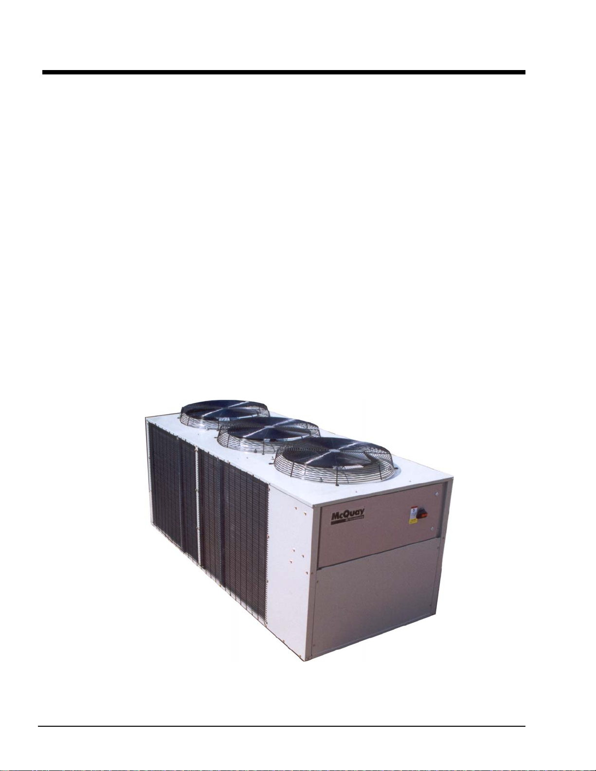
Figure 1, Model ACZ 033, 30-ton Condensing Unit
4 Catalog ACZ-AGZB1-1
Page 5

Design Features
The McQuay air-cooled, scroll compressor units are a product of the McQuay commitment to offer
quiet, reliable, energy efficient equipment. These units incorporate high quality compressors, state-ofthe-art coil design, and innovative packaging.
Construction
Factory assembled and mounted on a heavy-gauge steel channel base. The base rails, supports and cabinetry are
powder-coat painted. The base distributes the unit weight for roof loading. Varied and convenient installation is
possible by virtue of the unit's small footprint.
Compressors
Copeland’s Compliant Scroll tandem compressors are used. These rugged hermetic compressors are
constructed with an integral cast iron frame, cast iron scrolls, three Teflon impregnated bearings, and three oil
filtration devices for each compressor.
Using Copeland's Compliant Scroll tandem compressors provides two steps of capacity modulation. One
compressor can run alone, depending on the load of the system, utilizing the entire unit’s condenser surface,
which results in excellent part-load efficiency. The refrigerant circuit has specially designed oil and gas
equalization lines to control oil migration.
The design also offers radial and axial compliance (no tip seals), a large internal volume for liquid handling, a
removable suction screen, and a rotary dirt trap and oil screen. In addition, the compressor is self-compensating
for wear, handles liquid and debris, and inherently yields the highest efficiency for its class.
This well protected compressor includes a solid-state motor protection module, 4 individual motor-winding
sensors, a patented internal discharge temperature probe, and a patented shutdown feature that prevents reverse
rotation. An internal discharge check valve helps prevent shutdown noise and comes standard with high and
low pressure taps with Schrader valves, a sight glass, an oil level adjustment valve, and an off cycle crankcase
heater.
Units are available in 60 Hertz electrical voltage configurations from 208 to 575 volt operating at 3500 rpm.
Condenser Coils
Condenser coils have internally enhanced seamless copper tubes arranged in a staggered row pattern. The coils
are mechanically expanded into McQuay lanced and rippled aluminum fins with full fin collars. A variety of
optional coil material and coatings are available for corrosive atmospheres. The external condenser coils are
fitted with a protective wire mesh guard as standard equipment.
Condenser Fans and Motors
Multiple direct-drive, dynamically balanced, propeller fans operate in formed venturi openings at low tip
speeds for maximum efficiency and minimum noise and vibration. A heavy-gauge vinyl-coated fan guard
protects each fan.
Each condenser fan motor is heavy-duty, 3-phase, Totally Enclosed Air Over (TEAO) with permanently
lubricated ball bearings and inherent overload protection. SpeedTrol option includes a single-phase motor with
fan speed control on the lead fan.
Evaporator
Stainless steel, brazed plate evaporators are used on the AGZ units. They have counter-flow operation and very
high efficiencies.
Catalog ACZ-AGZB1-1
5
Page 6

Electrical Control Center
Operating and equipment protection controls and motor starting components are separately housed in a
centrally located, weather-resistant control panel with hinged and tool-locked doors. In addition to the
MicroTech II controller described in the next sections, the following components are housed in the panel:
Standard single-point, terminal block connection
Control, input, and output terminal block
Control transformer
Phase voltage monitor with under/over voltage and phase reversal protection
Fan contactors with short circuit protective devices
The standard FanTrol head pressure control system controls refrigerant discharge pressure by fan
staging. The FanTrol system cycles condenser fans based on discharge pressure and outdoor temperature and
is designed for operation down to 35°F (1.7°C).
Optional SpeedTrol™ control using both fan cycling and fan speed control on the lead fan per circuit and
allows operation to 0°F (-18°C) outdoor temperature.
Mechanical high pressure cutout
Power connections are per following table:
Power Connection
ACZ 010-039, Single-Point Connection Std. Opt Not Avail. Opt. Opt.
AGZ 010-034 Single Point Connection Std. Opt Not Avail. Opt. Opt.
Power
Block
Disc.
Swt.
Comp.
Circuit
Breakers
Definitions:
1. Power Block: An electrical device to directly accept field wiring without any disconnecting means.
2. Disconnect Switch: A molded case switch that accepts field wiring and disconnects main power to the
entire unit or each main power supply if the multi-point power supply option is selected. This option does
not provide overcurrent protection.
3. Unit Circuit Breaker with High Interrupting Capacity: A molded case circuit breaker acting as the
main disconnect switch with short circuit current rating (formally known as “withstand”). One circuit
breaker is provided. The circuit breaker provides overcurrent protection for the power supply.
4. Control Panel High Short Circuit Current Rating: (Previously known as “withstand rating”). The
entire control panel is designed for short circuit current rating. In the event of a short circuit, the damage
is contained within the control panel enclosure.
High Interr
Disconnect Switch
Current Rating
High Short Circuit
Current Rating w/
Disconnect Switch
Control System
The MicroTech II advanced DDC unit controller surpasses all other microprocessor-based unit control
systems available today on this class of equipment. This powerful, user-friendly control system provides the
flexibility and performance needed for either stand-alone unit operation or the controller can be easily tied
into your building automation system of choice using McQuay’s exclusive Open Choices feature that
allows you to choose from open standard protocols such as BACnet, Modbus, and L
communicate easily with the building automation system that best meets your facility requirements. These
optional communications modules are available factory-installed or can be easily field installed.
MicroTech II’s state-of-the-art design will not only permit the unit to run more efficiently, but will also
simplify troubleshooting if a system failure occurs. Every MicroTech II controller is programmed and tested
prior to shipment.
Operator-friendly
The MicroTech II control menu structure is separated into four distinct categories that provide the operator or
service technician with a full description of current unit status, control parameters, and alarms. Security
protection helps prevent unauthorized changing of the setpoints and control parameters.
MicroTech II continuously performs self-diagnostic checks, pressures and protection devices, monitoring
system temperatures, and it will automatically shutdown a compressor, or the entire unit, if a fault occurs. The
6 Catalog ACZ-AGZB1-1
onTalk to
Page 7

cause of the shutdown will be retained in memory and can be easily displayed in English or metric units for
operator review.
The MicroTech II unit controller can also retain and display the time that the fault occurred and the operating
conditions that were present at the time of the fault, an extremely useful feature for troubleshooting. In
addition to displaying alarm diagnostics, the MicroTech II controller also provides the operator with a
warning of pre-alarm conditions. Alarm notification data can also be passed on to your BAS through an
optional communications module.
Staging
On ACZ condensing units, temperature control for the system is provided by the installer through a field
supplied temperature controller. The field-supplied staging signals are provided to the MicroTech II controller
which correspondingly activates and deactivates the scroll compressors. The temperature controller is
required to close normally-open 24 volt contacts on a demand for cooling. These closure signals are field
wired to the terminal strip (TB2) in the condensing unit. Refer to the typical field wiring diagram on page
for details. Two control stages are required:
Lead/lag is automatic and switched based on operating hours and compressor starts.
40
Equipment Protection
The unit is protected in two ways: (1) by alarms that shut the unit down and require manual reset to restore
unit operation and (2) by limit alarms that reduce unit operation in response to some out-of-limit condition.
Shut down alarms can activate a remote alarm signal. Limit alarms activate a signal on the controller.
Shutdown Alarms
High condenser pressure
No chilled water flow
Motor protection system
Phase voltage protection (Optional on ACZ-B and AGZ-B)
Outside ambient temperature
Sensor failures
Limit Alarms
Condenser pressure stage down, unloads unit at high discharge pressures
Low ambient lockout, shuts off unit at low ambient temperatures
Low evaporator pressure hold, holds stage #1 until pressure rises
Low evaporator pressure unload, shuts off stage #2
Unit Enable Selection
Enables unit operation from either local keypad, digital input, or BAS
Unit Mode Selection
Selects standard cooling, or test operation mode
Digital Inputs
Unit off switch
Remote start/stop
Flow switch
Digital Outputs
Shutdown alarm; field wired, activates on an alarm condition, off when alarm is cleared
Evaporator pump or air handler fan motor; field wired, starts when unit is set to start
Catalog ACZ-AGZB1-1
7
Page 8

Condenser fan control
The MicroTech II controller provides control of condenser fans. The controller stages condenser fans based
on discharge pressure.
Building Automation System (BAS) Interface
The following BAS standard protocols are supported through McQuay’s Open Choices option:
BACnet/IP
BACnet MS/TP
BACnet Ethernet
L
onTalk
Modbus
The following functions are generally available depending on the application and protocol in use:
Enable/disable operation
Select operating mode
Set the network limit variable
Read all digital and analog inputs and outputs
Read operating mode and status
Send a description of each alarm when it occurs
Keypad/Display
A 4-line by-20 character/line liquid crystal display and 6-key keypad is mounted on the unit controller. Its
layout is shown in
Figure 2.
Figure 2, MicroTech II
Keypad
Menu Button
"Enter" Button
The four arrow buttons (UP, DOWN, LEFT, RIGHT) have three modes of use.
Scroll between data screens as indicated by the arrows (default mode).
Select a specific data screen in a hierarchical fashion using dynamic labels on the right side of the display
(this mode is entered by pressing the MENU button).
Change field values in edit mode.
8 Catalog ACZ-AGZB1-1
Page 9

Figure 3, ACZ/AGZ-B Control Panel
Optional Remote Interface Panel
The ACZ/AGZ units can be individually equipped with a
remote user interface. It provides convenient access to
unit diagnostics and control adjustments, remote from
the condensing unit panel. A separate panel is required
for each chiller on a job site.
Each remote user interface is similar to its unit-mounted
counterpart and offers the same functionality, including:
Touch-sensitive keypad with a 4 line by 20-character
display format
Digital display of messages in English language
All operating conditions, system alarms, control
parameters
Features
Can be wired up to 1,640 feet (500 meters) from the
unit for flexibility in placing each remote user interface
within your building.
The main control is isolated from the remote user interface
wiring so that wiring problems are less likely to damage the
unit user interface.
Can be placed on a desk or surface or recessed wall mounted.
Benefits
Allows you to access the user interface for each unit from
one location, inside the building.
Users need to learn one format because the remote user
interface is identical to the unit-mounted version.
No additional field commissioning is required for the remote user interface.
Can be retrofit after unit installation.
All the BAS communications options are still available with the remote interface panel.
Figure 4, Remote Interface Panel Dimensions
Cable and Wiring Recommendations
No more than 1,640 feet (500 meters) of wiring can be used to connect the remote user interface to the unit.
Power: AWG 22 twisted pair cable.
Communications: Belden 9841 or equal AWG 22 twisted pair.
A separate small communication terminal board is used at the unit and at the remote panel.
Catalog ACZ-AGZB1-1
9
Page 10

Figure 5, Remote User Interface Wiring Diagram
p
D
A
r
Chiller Terminal Board
0 1 2 3 4 5 6
sc
pLAN
cable
A
pLAN phone style
cable to J10 of
chiller Unit control
Note:
Maximum distance between terminal
blocks is 1640 feet (500 m)
Power is supplied through
30 Vdc +
Power Common
RX+/Tx+
Rx-/Tx-
Shield
AWG22 twisted pair cable
Communications cable is
Belden 9841 or equivalent
WG22 twisted pai
Display Terminal Board
0 1 2 3 4 5 6
sc
10 Catalog ACZ-AGZB1-1
Page 11

ACZ Condensing Unit Performance
Selection Procedure
ACZ condensing units are selected in conjunction with some kind of evaporator equipment. The ACZ ratings
are based on saturated suction temperature at the compressor inlet and on ambient air dry-bulb temperature. For
a system selection, the ACZ condensing unit is usually selected first, and then the line loss added to the
condensing unit saturated suction temperature to determine the saturated evaporating temperature. This
temperature is then used for the selection of the evaporator, whether it is a DX cooling coil or water heat
exchanger. The pipe size can be determined from procedures and data in the Refrigerant Piping Section. For
selection purposes, the tubing size is based on a pressure equivalent of a two-degree F line loss (equal to about
3-psi pressure drop).
The correction for altitude found in
the correction factor to ascertain the necessary unit capacity in the Capacity Tables.
R-407C NOTE: R-407C is an azeotrope and as such has a glide characteristic. An evaporator mid-point
temperature will be about four-degrees higher than the dew point temperature. For example, an R-22 evaporator
selected at a 40F evaporating temperature would be comparable to a 44F temperature with R-407C.
Selection example, Inch-Pound units
Given:
200 Mbh job requirement 95°F ambient temperature
40F saturated suction temperature 2,000 foot altitude
R-22
1. To select the correct size unit, correct for altitude by dividing the required capacity by the correction
factor found in
200 Mbh required / 0.986 factor = 202 Mbh corrected requirement.
2. From
Table 2 on the following page, an ACZ 020 at the given conditions will produce 202.5 Mbh with a
unit power input of 20.0 kW and a unit EER of 10.1.
3. Correct for altitude:
Capacity: 202.5 Mbh x 0.986 = 200 Mbh
Power: 20.0 kW x 1.009 = 20.2 kW
EER: 10.1 EER x 0.986/1.009 = 9.9 EER
4. An evaporator would be selected at 42F saturated evaporating temperature.
Table 1.
Table 1 is applied, if applicable, by dividing the required job capacity by
Selection example-SI units
Use the same procedure as for Inch-Pounds but use SI tables and units.
Application Adjustment Factors
Altitude Correction Factors
Performance tables are based at sea level. Elevations other than sea level affect the performance of the unit.
The decreased air density will reduce condenser capacity, consequently reducing the unit's performance.
Table 1, Altitude Correction Factors
Altitude Capacity Power
Sea Level 1.000 1.000
2000 ft (610 m) 0.986 1.009
4000 ft (1220) m 0.973 1.021
6000 ft (1830) m 0.959 1.031
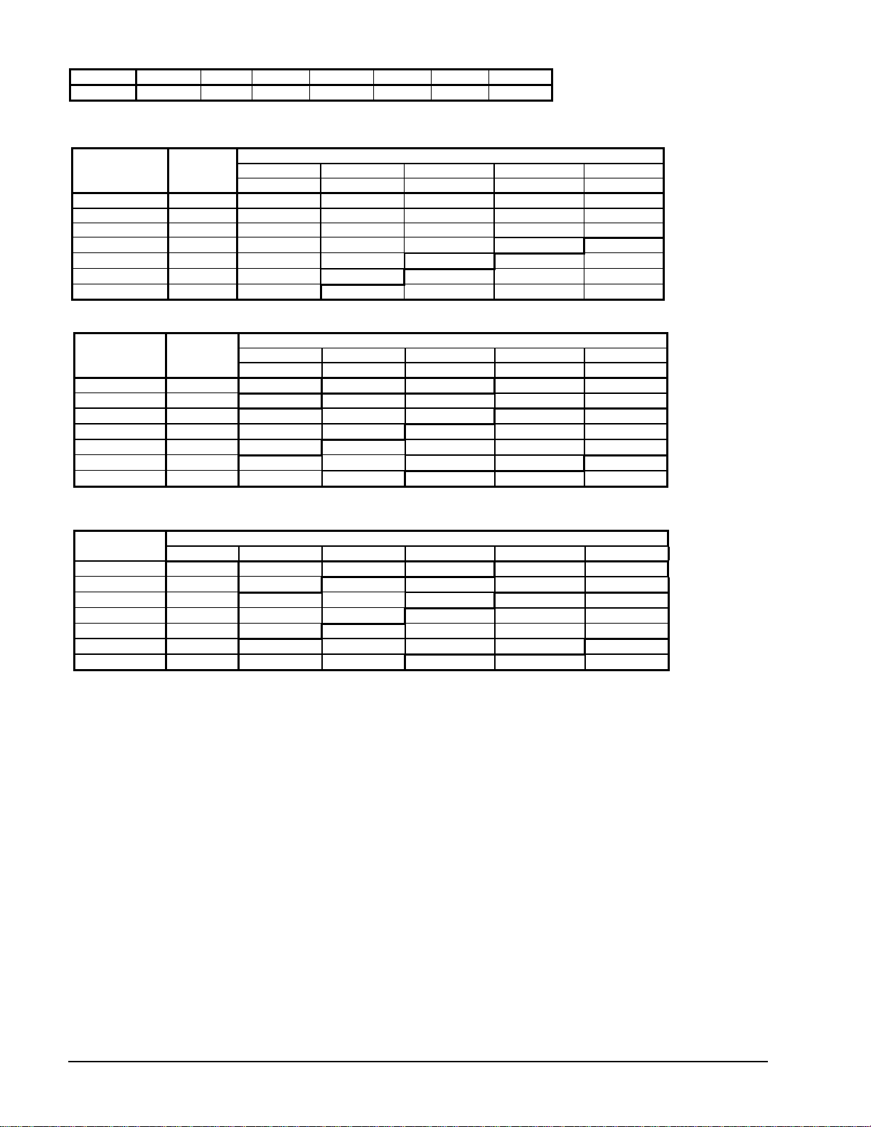
ACZ Performance Data
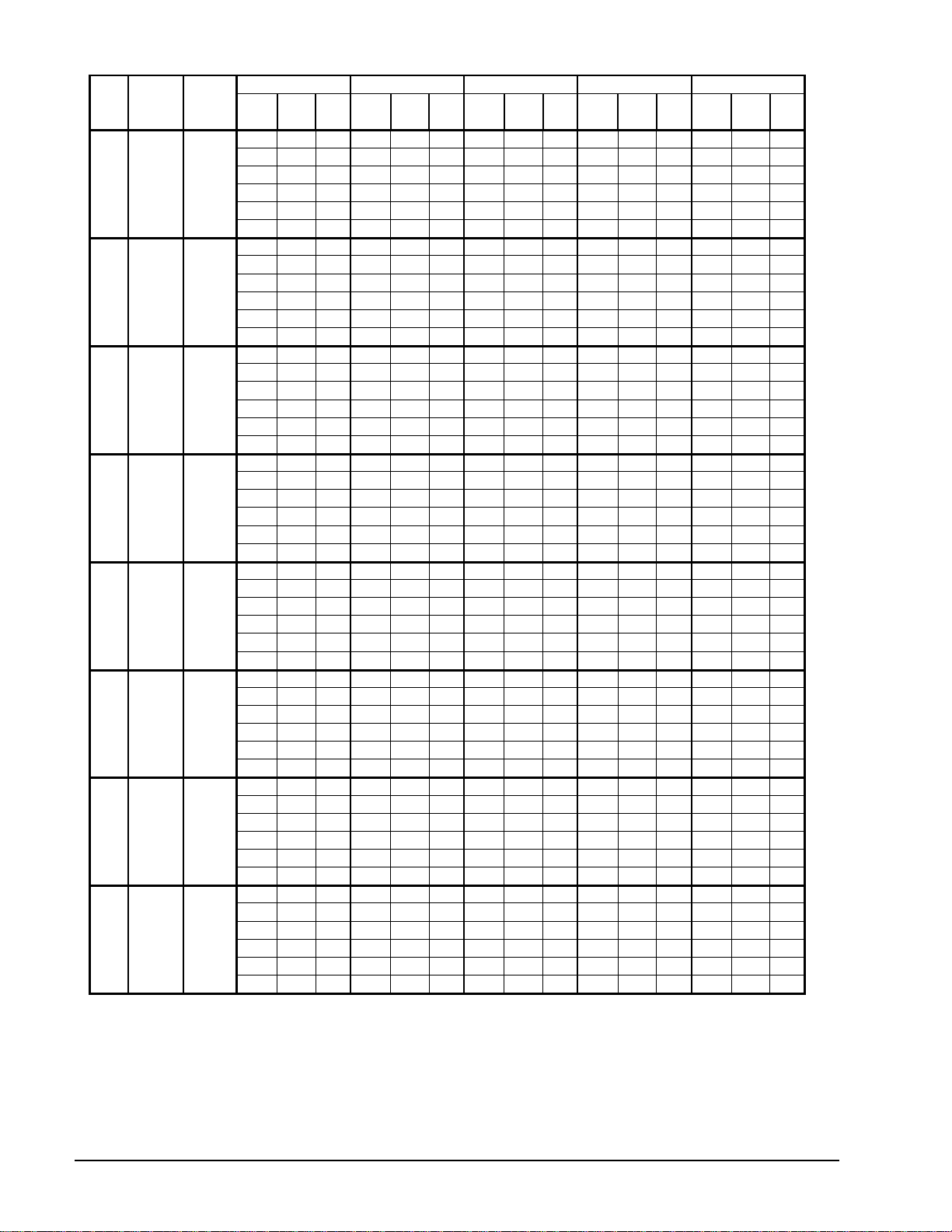
Table 2, R-22, I-P Units, 60 Hz
ACZ Sat. Fan &
Catalog ACZ-AGZB1-1
Ambient Air Temperature (F)
11
Page 12
75 85 95 105 115
Unit
PWR
Unit
Unit
PWR
Unit
Unit
PWR
Unit
Unit
PWR
Unit
Unit
PWR
Mbh
kWi
EER
Mbh
kWi
EER
Mbh
kWi
EER
Mbh
kWi
EER
Mbh
kWi
30
35
010
013
016
020
025
028
033
039
NOTES:
1. Ratings based on R-22, and sea level altitude.
2. Interpolation is allowed; extrapolation is not permitted. Consult McQuay for performance outside the cataloged ratings.
3. KWi and EER are for the entire unit, including compressors, fan motors and control power.
4. Rated in accordance with ARI Standard 365-2002.
40
45
50
55
30
35
40
45
50
55
30
35
40
45
50
55
30
35
40
45
50
55
30
35
40
45
50
55
30
35
40
45
50
55
30
35
40
45
50
55
30
35
40
45
50
55
1.8 87.4 8.0 10.9 86.2 8.3 10.4 81.3 8.9 9.1 76.4 9.7 7.9 71.6 10.5 6.8
1.8 97.1 8.1 12.0 94.7 8.4 11.3 89.8 9.1 9.9 84.9 9.8 8.7 78.9 10.6 7.4
1.8 106.8 8.3 12.9 104.4 8.6 12.1 98.3 9.2 10.7 93.4 10.0 9.4 87.4 10.8 8.1
1.8 116.5 8.4 13.9 114.1 8.7 13.1
1.8 127.4 8.6 14.8 125.0 8.9 14.1 118.9 9.6 12.4 111.6 10.3 10.8 105.6 11.2 9.4
1.8 138.3 8.9 15.6 135.9 9.2 14.8 128.6 9.8 13.1 122.6 10.6 11.6 115.3 11.4 10.1
1.8 114.7 10.7 10.7 111.0 11.2 9.9 106.1 12.2 8.7 99.9 13.3 7.5 93.7 14.5 6.5
1.8 128.3 11.0 11.6 124.6 11.4 10.9 118.4 12.5 9.5 112.2 13.6 8.3 104.8 14.8 7.1
1.8 143.1 11.2 12.7 139.4 11.7 11.9 133.2 12.7 10.5 125.8 13.8 9.1 118.4 15.1 7.8
1.8 159.1 11.6 13.7 155.4 12.1 12.9
1.8 175.1 12.0 14.7 171.4 12.4 13.9 162.8 13.4 12.2 155.4 14.5 10.7 145.5 15.8 9.2
1.8 192.4 12.3 15.7 188.7 12.8 14.8 180.1 13.7 13.1 170.2 14.8 11.5 160.3 16.2 9.9
1.8 157.8 15.6 10.1 154.0 16.3 9.5 146.4 17.8 8.2 138.7 19.5 7.1 131.1 21.2 6.2
1.8 174.4 15.9 11.0 169.3 16.6 10.2 161.6 18.0 9.0 152.7 19.7 7.8 143.8 21.5 6.7
1.8 190.9 16.1 11.8 187.1 16.8 11.1 178.2 18.3 9.7 169.3 20.0 8.4 159.1 21.9 7.3
1.8 210.0 16.5 12.7 204.9 17.2 11.9
1.8 230.4 16.8 13.7 225.3 17.5 12.9 213.8 19.0 11.2 203.6 20.7 9.8 190.9 22.6 8.5
1.8 252.0 17.3 14.6 246.9 18.0 13.7 234.2 19.5 12.0 222.7 21.2 10.5 210.0 23.0 9.1
1.8 181.7 16.8 10.8 178.1 17.5 10.2 168.3 19.1 8.8 158.6 20.9 7.6 148.8 22.7 6.6
1.8 200.0 17.2 11.6 195.2 17.9 10.9 185.4 19.5 9.5 174.4 21.3 8.2 163.5 23.2 7.1
1.8 219.6 17.6 12.5 214.7 18.3 11.8 202.5 20.0 10.1 191.5 21.8 8.8 179.3 23.7 7.6
1.8 240.3 18.0 13.4 234.2 18.8 12.5
1.8 261.0 18.5 14.1 254.9 19.3 13.2 241.5 20.9 11.6 228.1 22.7 10.1 214.7 24.7 8.7
1.8 284.2 19.0 15.0 276.9 19.8 14.0 262.3 21.4 12.3 247.6 23.3 10.6 233.0 25.3 9.2
2.7 242.9 22.7 10.7 237.9 23.6 10.1 225.4 25.7 8.8 211.6 27.9 7.6 197.8 30.4 6.5
2.7 267.9 23.2 11.6 261.7 24.1 10.9 247.9 26.2 9.5 234.1 28.5 8.2 219.1 31.0 7.1
2.7 294.2 23.7 12.4 286.7 24.7 11.6 273.0 26.8 10.2 256.7 29.1 8.8 240.4 31.6 7.6
2.7 321.8 24.3 13.2 314.3 25.3 12.4
2.7 351.8 25.1 14.0 343.1 26.0 13.2 325.5 28.1 11.6 306.8 30.4 10.1 288.0 33.0 8.7
2.7 381.9 25.7 14.9 373.1 26.7 14.0 354.3 28.8 12.3 334.3 31.1 10.8 314.3 33.8 9.3
2.7 266.8 26.1 10.2 260.5 27.1 9.6 246.7 29.4 8.4 231.6 32.0 7.2 216.5 34.8 6.2
2.7 294.5 26.7 11.0 287.0 27.8 10.3 271.9 30.1 9.0 255.5 32.7 7.8 239.2 35.5 6.7
2.7 322.2 27.5 11.7 314.7 28.5 11.0 298.3 30.9 9.7 280.7 33.5 8.4 263.1 36.4 7.2
2.7 352.4 28.2 12.5 343.6 29.3 11.7
2.7 383.9 29.1 13.2 375.1 30.1 12.4 356.2 32.5 11.0 336.1 35.2 9.5 314.7 38.1 8.3
2.7 417.9 29.9 14.0 407.8 31.0 13.2 386.4 33.4 11.6 365.0 36.0 10.1 342.4 39.1 8.8
2.7 314.1 30.0 10.5 307.0 31.4 9.8 291.6 34.4 8.5 275.0 37.6 7.3 258.4 41.0 6.3
2.7 346.1 30.8 11.2 337.8 32.1 10.5 320.0 35.1 9.1 302.2 38.4 7.9 284.4 42.0 6.8
2.7 379.3 31.6 12.0 369.8 33.0 11.2 350.8 36.1 9.7 331.9 39.3 8.4 311.7 42.9 7.3
2.7 413.6 32.5 12.7 404.1 33.9 11.9
2.7 450.4 33.5 13.4 439.7 34.9 12.6 418.4 38.0 11.0 395.9 41.4 9.6 372.1 45.1 8.3
2.7 489.5 34.6 14.2 477.6 36.0 13.3 453.9 39.1 11.6 429.0 42.5 10.1 403.0 46.2 8.7
2.7 390.0 40.8 9.6 380.5 42.4 9.0 360.2 46.1 7.8 337.7 50.0 6.8 312.7 54.1 5.8
2.7 429.2 41.9 10.2 418.5 43.7 9.6 395.9 47.4 8.3 370.9 51.4 7.2 344.8 55.7 6.2
2.7 469.6 43.2 10.9 457.7 45.0 10.2 432.8 48.8 8.9 406.6 52.9 7.7 378.1 57.2 6.6
2.7 511.2 44.5 11.5 498.2 46.4 10.7
2.7 555.2 46.1 12.0 542.1 47.9 11.3 512.4 51.8 9.9 482.7 56.0 8.6 449.4 60.5 7.4
2.7 602.8 47.7 12.6 587.3 49.5 11.9 555.2 53.4 10.4 521.9 57.8 9.0 487.5 62.3 7.8
108.0 9.4 11.5
148.0 13.0 11.4
196.0 18.7 10.5
222.0 20.4 10.9
298.0 27.3 10.9
326.0 31.7 10.3
384.0 36.9 10.4
472.0 50.2 9.4
101.9 10.1 10.1 95.9 11.0 8.7
139.4 14.1 9.9 132.0 15.5 8.5
185.8 20.4 9.1 174.4 22.2 7.8
209.8 22.2 9.5 196.4 24.2 8.1
281.7 29.7 9.5 264.2 32.3 8.2
308.4 34.3 9.0 288.2 37.2 7.7
362.7 40.3 9.0 341.3 44.0 7.8
443.5 54.4 8.1 413.7 58.8 7.0
Unit
EER
12 Catalog ACZ-AGZB1-1
Page 13
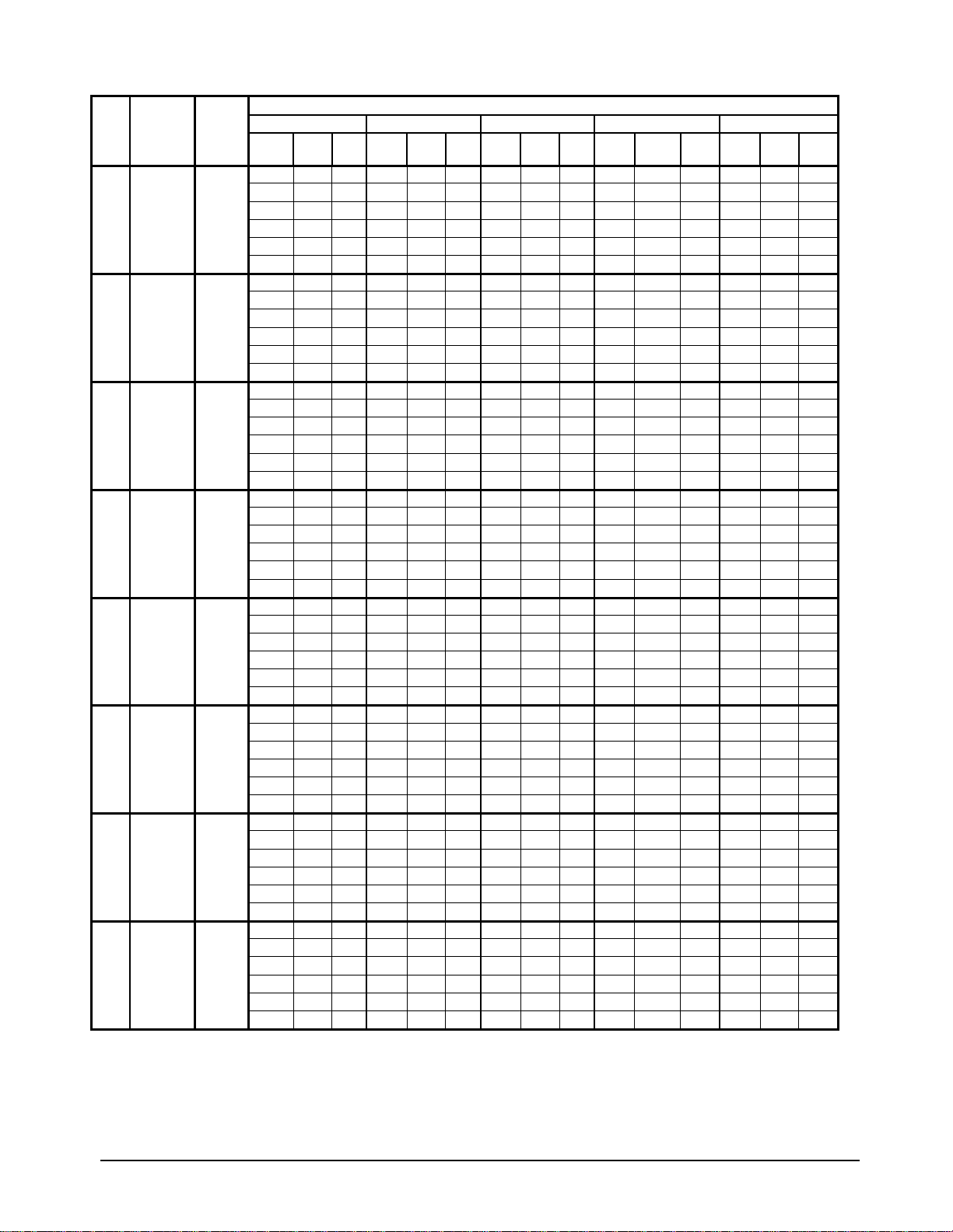
Table 3, R-407C, I-P Units, 60 Hz
Suction
ACZ
Dewpoint
Unit
Size
NOTES:
1. Ratings based on R-407C, and sea level altitude.
2. Interpolation is allowed; extrapolation is not permitted. Consult McQuay for performance outside the cataloged ratings.
3. KWi and EER are for the entire unit, including compressors, fan motors and control power.
4. Rated in accordance with ARI Standard 365-2002.
010
013
016
020
025
028
033
039
Temp
(F)
30 1.8 85.6 8.2 10.4 84.4 8.6 9.9 79.7 9.2 8.7 74.9 10.0 7.5 70.2 10.8 6.5
35 1.8 95.1 8.3 11.4 92.8 8.7 10.7 88.0 9.4 9.4 83.2 10.1 8.2 77.3 10.9 7.1
40 1.8 104.7 8.6 12.2 102.3 8.9 11.5 96.3 9.5 10.2 91.6 10.3 8.9 85.6 11.1 7.7
45 1.8 114.2 8.7 13.2 111.8 9.0 12.5
50 1.8 124.9 8.9 14.1 122.5 9.2 13.4 116.5 9.9 11.8 109.4 10.6 10.3 103.5 11.5 9.0
55 1.8 135.6 9.2 14.8 133.2 9.5 14.0 126.1 10.1 12.5 120.1 10.9 11.0 113.0 11.7 9.6
30 1.8 112.4 11.1 10.2 108.8 11.6 9.4 103.9 12.5 8.3 97.9 13.7 7.1 91.9 15.0 6.1
35 1.8 125.7 11.4 11.1 122.1 11.8 10.3 116.0 12.9 9.0 110.0 14.0 7.8 102.7 15.3 6.7
40 1.8 140.2 11.6 12.1 136.6 12.1 11.3 130.5 13.1 10.0 123.3 14.2 8.7 116.0 15.6 7.4
45 1.8 155.9 12.0 13.0 152.3 12.4 12.2
50 1.8 171.6 12.3 13.9 168.0 12.8 13.2 159.5 13.8 11.5 152.3 15.0 10.2 142.6 16.3 8.8
55 1.8 188.6 12.6 14.9 184.9 13.2 14.0 176.5 14.1 12.5 166.8 15.3 10.9 157.1 16.7 9.4
30 1.8 154.7 16.1 9.6 150.9 16.8 9.0 143.4 18.3 7.8 136.0 20.1 6.8 128.5 21.9 5.9
35 1.8 170.9 16.4 10.4 165.9 17.1 9.7 158.4 18.5 8.5 149.7 20.3 7.4 140.9 22.2 6.3
40 1.8 187.1 16.7 11.2 183.3 17.4 10.6 174.6 18.9 9.2 165.9 20.7 8.0 155.9 22.6 6.9
45 1.8 205.8 17.0 12.1 200.8 17.7 11.3
50 1.8 225.8 17.4 13.0 220.8 18.1 12.2 209.5 19.6 10.7 199.6 21.4 9.3 187.1 23.3 8.0
55 1.8 247.0 17.8 13.8 242.0 18.5 13.0 229.5 20.1 11.4 218.3 21.9 10.0 205.8 23.7 8.7
30 1.8 178.1 17.3 10.3 174.5 18.0 9.7 165.0 19.7 8.4 155.4 21.5 7.2 145.8 23.4 6.2
35 1.8 196.0 17.7 11.1 191.3 18.4 10.4 181.7 20.1 9.0 170.9 21.9 7.8 160.2 23.9 6.7
40 1.8 215.2 18.1 11.9 210.4 18.8 11.2 198.4 20.6 9.6 187.7 22.5 8.4 175.7 24.4 7.2
45 1.8 235.5 18.5 12.7 229.5 19.4 11.9
50 1.8 255.8 19.1 13.4 249.8 19.9 12.6 236.7 21.5 11.0 223.5 23.4 9.6 210.4 25.4 8.3
55 1.8 278.5 19.6 14.2 271.4 20.4 13.3 257.0 22.0 11.7 242.7 24.0 10.1 228.3 26.1 8.8
30 2.7 238.0 23.4 10.2 233.1 24.3 9.6 220.9 26.5 8.3 207.4 28.7 7.2 193.9 31.3 6.2
35 2.7 262.6 23.9 11.0 256.5 24.9 10.3 243.0 27.0 9.0 229.5 29.4 7.8 214.7 32.0 6.7
40 2.7 288.4 24.4 11.8 281.0 25.5 11.0 267.5 27.7 9.7 251.5 30.0 8.4 235.6 32.6 7.2
45 2.7 315.4 25.1 12.6 308.0 26.1 11.8
50 2.7 344.8 25.8 13.3 336.2 26.8 12.5 319.0 29.0 11.0 300.6 31.3 9.6 282.2 34.0 8.3
55 2.7 374.3 26.5 14.1 365.7 27.6 13.3 347.3 29.7 11.7 327.6 32.1 10.2 308.0 34.9 8.8
30 2.7 261.5 26.9 9.7 255.3 28.0 9.1 241.8 30.3 8.0 227.0 33.0 6.9 212.2 35.9 5.9
35 2.7 288.6 27.6 10.5 281.2 28.7 9.8 266.4 31.1 8.6 250.4 33.8 7.4 234.4 36.6 6.4
40 2.7 315.8 28.3 11.1 308.4 29.4 10.5 292.3 31.9 9.2 275.1 34.5 8.0 257.8 37.5 6.9
45 2.7 345.4 29.1 11.9 336.7 30.2 11.1
50 2.7 376.2 30.0 12.5 367.6 31.1 11.8 349.1 33.5 10.4 329.3 36.3 9.1 308.4 39.3 7.8
55 2.7 409.5 30.9 13.3 399.7 32.0 12.5 378.7 34.4 11.0 357.7 37.2 9.6 335.5 40.3 8.3
30 2.7 307.8 30.9 10.0 300.8 32.3 9.3 285.7 35.4 8.1 269.5 38.8 7.0 253.2 42.3 6.0
35 2.7 339.2 31.8 10.7 331.0 33.1 10.0 313.6 36.2 8.7 296.2 39.6 7.5 278.8 43.3 6.4
40 2.7 371.7 32.6 11.4 362.4 34.0 10.7 343.8 37.2 9.2 325.2 40.5 8.0 305.5 44.3 6.9
45 2.7 405.4 33.6 12.1 396.1 35.0 11.3
50 2.7 441.4 34.6 12.8 430.9 36.0 12.0 410.0 39.2 10.5 387.9 42.7 9.1 364.7 46.5 7.8
55 2.7 479.7 35.7 13.5 468.1 37.1 12.6 444.8 40.3 11.0 420.5 43.8 9.6 394.9 47.7 8.3
30 2.7 382.2 42.1 9.1 372.8 43.8 8.5 353.0 47.6 7.4 330.9 51.6 6.4 306.4 55.8 5.5
35 2.7 420.6 43.2 9.7 410.1 45.0 9.1 388.0 48.9 7.9 363.5 53.1 6.9 337.9 57.4 5.9
40 2.7 460.2 44.6 10.3 448.6 46.4 9.7 424.1 50.3 8.4 398.5 54.5 7.3 370.5 59.0 6.3
45 2.7 501.0 46.0 10.9 488.2 47.9 10.2
50 2.7 544.1 47.6 11.4 531.3 49.4 10.8 502.2 53.4 9.4 473.0 57.8 8.2 440.4 62.5 7.1
55 2.7 590.7 49.2 12.0 575.6 51.1 11.3 544.1 55.1 9.9 511.5 59.6 8.6 477.7 64.3 7.4
Fan &
Control
Power
(kW)
75 85 95 105 115
Unit
PWR
Unit
Unit
Mbh
kWi
EER
PWR
Mbh
Ambient Air Temperature (F)
Unit
Unit
kWi
EER
PWR
Mbh
kWi
105.8 9.7 10.9
145.0 13.4 10.8
192.1 19.3 10.0
217.6 21.0 10.4
292.0 28.2 10.4
319.5 32.6 9.8
376.3 38.1 9.9
462.6 51.8 8.9
Unit
Unit
PWR
Unit
EER
Mbh
kWi
99.9 10.4 9.6 93.9 11.3 8.3
136.6 14.6 9.4 129.3 15.9 8.1
182.1 21.0 8.7 170.9 22.9 7.5
205.6 22.9 9.0 192.5 24.9 7.7
276.1 30.7 9.0 258.9 33.4 7.8
302.2 35.4 8.5 282.5 38.4 7.4
355.4 41.6 8.5 334.5 45.4 7.4
434.6 56.2 7.7 405.5 60.6 6.7
EER
Unit
Mbh
PWR
kWi
Unit
EER
Catalog ACZ-AGZB1-1
13
Page 14

Table 4, R-22, SI Units, 60 Hz,
Sat.
ACZ
Suction
Unit
Temp
Size
010
013
016
020
025
028
033
039
NOTES:
1. Ratings based on R-22, and sea level altitude.
2. Interpolation is allowed; extrapolation is not permitted. Consult McQuay for performance outside the cataloged ratings.
3. KWi and EER are for the entire unit, including compressors, fan motors and control power.
(C)
-1
11
13
-1
11
13
-1
11
13
-1
11
13
-1
11
13
-1
11
13
-1
11
13
-1
11
13
Fan &
Control
Power
(kW)
1.8 25.7 7.6 3.4 24.4 8.3 2.9 23.2 8.8 2.6 21.7 9.6 2.3 20.3 10.5 1.9
2
5
8
2
5
8
2
5
8
2
5
8
2
5
8
2
5
8
2
5
8
2
5
8
1.8 28.5 7.8 3.6 27.1 8.4 3.2 25.9 9.0 2.9 24.3 9.8 2.5 22.6 10.7 2.1
1.8 31.6 7.9 4.0 30.1 8.6 3.5 28.6 9.2 3.1 26.9 10.0 2.7 25.2 10.9 2.3
1.8 34.8 8.1 4.3 33.1 8.8 3.8
1.8 38.2 8.4 4.5 36.5 9.0 4.0 34.8 9.6 3.6 32.8 10.4 3.2 30.8 11.3 2.7
1.8 40.7 8.5 4.8 38.7 9.1 4.3 37.1 9.7 3.8 34.9 10.6 3.3 32.7 11.5 2.9
1.8 33.5 10.2 3.3 31.8 11.2 2.8 30.3 12.1 2.5 28.5 13.3 2.1 26.5 14.7 1.8
1.8 37.9 10.5 3.6 36.0 11.4 3.1 34.4 12.4 2.8 32.4 13.6 2.4 30.1 15.0 2.0
1.8 42.6 10.8 3.9 40.5 11.8 3.4 38.7 12.7 3.0 36.5 13.9 2.6 34.1 15.3 2.2
1.8 47.6 11.2 4.2 45.3 12.2 3.7
1.8 52.9 11.6 4.6 50.4 12.5 4.0 48.2 13.4 3.6 45.5 14.6 3.1 42.7 16.0 2.7
1.8 56.5 11.9 4.8 53.9 12.8 4.2 51.6 13.6 3.8 48.7 14.8 3.3 45.7 16.3 2.8
1.8 46.4 14.9 3.1 43.9 16.4 2.7 42.0 17.6 2.4 39.6 19.5 2.0 37.1 21.4 1.7
1.8 51.5 15.3 3.4 48.9 16.6 2.9 46.8 18.0 2.6 44.1 19.8 2.2 41.3 21.7 1.9
1.8 57.0 15.6 3.7 54.2 17.0 3.2 51.9 18.3 2.8 49.0 20.1 2.4 45.9 22.1 2.1
1.8 63.1 15.9 4.0 59.9 17.3 3.5
1.8 69.7 16.3 4.3 66.2 17.8 3.7 63.3 19.1 3.3 59.8 20.9 2.9 56.0 23.0 2.4
1.8 74.2 16.6 4.5 70.6 18.1 3.9 67.6 19.3 3.5 63.8 21.3 3.0 59.6 23.2 2.6
1.8 53.6 15.9 3.4 50.7 17.5 2.9 48.3 18.9 2.6 45.2 20.8 2.2 42.2 22.8 1.8
1.8 59.3 16.3 3.6 56.2 17.9 3.1 53.6 19.4 2.8 50.3 21.3 2.4 46.9 23.3 2.0
1.8 65.6 16.8 3.9 62.1 18.4 3.4 59.1 19.9 3.0 55.5 21.8 2.5 51.9 23.8 2.2
1.8 72.0 17.3 4.2 68.2 18.9 3.6
1.8 79.0 17.8 4.4 74.8 19.4 3.9 71.3 20.9 3.4 66.9 22.8 2.9 62.6 25.0 2.5
1.8 83.7 18.1 4.6 79.3 19.8 4.0 75.6 21.3 3.6 71.0 23.2 3.1 66.4 25.4 2.6
2.7 71.4 21.7 3.3 67.7 23.6 2.9 64.6 25.5 2.5 60.5 27.9 2.2 56.1 30.5 1.8
2.7 79.2 22.2 3.6 75.2 24.2 3.1 71.7 26.1 2.7 67.2 28.5 2.4 62.5 31.3 2.0
2.7 87.6 22.8 3.8 83.2 24.9 3.3 79.3 26.7 3.0 74.4 29.2 2.5 69.3 32.0 2.2
2.7 96.5 23.5 4.1 91.6 25.5 3.6
2.7 105.8 24.2 4.4 100.5 26.2 3.8 95.9 28.1 3.4 90.1 30.6 2.9 84.1 33.4 2.5
2.7 112.4 24.8 4.5 106.7 26.7 4.0 101.7 28.6 3.6 95.6 31.2 3.1 89.3 33.9 2.6
2.7 78.4 24.9 3.1 74.4 27.2 2.7 70.8 29.3 2.4 66.1 32.0 2.1 61.1 35.0 1.7
2.7 86.9 25.7 3.4 82.5 27.9 2.9 78.6 30.1 2.6 73.6 32.8 2.2 68.2 35.9 1.9
2.7 96.0 26.4 3.6 91.2 28.7 3.2 86.9 30.8 2.8 81.4 33.7 2.4 75.6 36.8 2.1
2.7 105.6 27.3 3.9 100.2 29.5 3.4
2.7 115.8 28.2 4.1 109.9 30.5 3.6 104.7 32.6 3.2 98.3 35.5 2.8 91.6 38.7 2.4
2.7 122.7 28.9 4.2 116.4 31.1 3.7 111.0 33.2 3.3 104.2 36.1 2.9 97.2 39.3 2.5
2.7 92.3 28.5 3.2 87.6 31.4 2.8 83.5 34.1 2.4 78.6 37.5 2.1 73.5 41.2 1.8
2.7 102.2 29.4 3.5 97.1 32.3 3.0 92.7 34.9 2.7 87.2 38.4 2.3 81.5 42.2 1.9
2.7 112.8 30.2 3.7 107.2 33.2 3.2 102.3 35.9 2.8 96.3 39.5 2.4 90.0 43.3 2.1
2.7 124.0 31.2 4.0 117.8 34.2 3.4
2.7 135.8 32.3 4.2 129.0 35.2 3.7 123.2 38.1 3.2 115.9 41.7 2.8 108.4 45.7 2.4
2.7 143.9 33.1 4.3 136.7 36.1 3.8 130.6 38.8 3.4 122.9 42.5 2.9 114.9 46.6 2.5
2.7 114.7 38.9 2.9 108.8 42.5 2.6 103.5 45.8 2.3 96.4 50.0 1.9 88.7 54.3 1.6
2.7 126.9 40.1 3.2 120.3 43.8 2.7 114.5 47.1 2.4 106.9 51.4 2.1 98.6 55.9 1.8
2.7 139.8 41.5 3.4 132.5 45.3 2.9 126.1 48.7 2.6 117.8 53.1 2.2 108.9 57.7 1.9
2.7 153.4 42.9 3.6 145.4 46.8 3.1
2.7 167.7 44.6 3.8 158.8 48.5 3.3 151.1 52.0 2.9 141.3 56.5 2.5 131.0 61.3 2.1
2.7 177.5 45.7 3.9 168.1 49.6 3.4 159.9 53.1 3.0 149.6 57.7 2.6 138.7 62.7 2.2
24°C 30°C 35°C 41°C 47°C
Unit
PWR
Unit
kW
kWi
COP
Unit kWPWR
kWi
Ambient Air Temperature (F)
Unit
Unit kWPWR
COP
31.7 9.4 3.4
43.4 13.0 3.3
57.4 18.7 3.1
65.1 20.4 3.2
87.3 27.3 3.2
95.5 31.7 3.0
112.5 36.9 3.0
138.3 50.2 2.8
kWi
Unit
COP
Unit kWPWR
29.8 10.2 2.9 27.9 11.1 2.5
40.9 14.2 2.9 38.2 15.6 2.4
54.2 20.5 2.6 50.7 22.5 2.2
61.1 22.2 2.7 57.0 24.4 2.3
82.1 29.9 2.7 76.6 32.7 2.3
89.6 34.5 2.6 83.4 37.7 2.2
105.9 40.5 2.6 99.0 44.5 2.2
129.3 54.7 2.4 119.8 59.5 2.0
kWi
Unit
COP
Unit kWPWR
kWi
Unit
COP
14 Catalog ACZ-AGZB1-1
Page 15
Table 5, R-407C, SI, 60 Hz
Suction
ACZ
Dewpoint
Unit
Size
NOTES:
Temp
(C)
-1
010
11
13
-1
013
11
13
-1
016
11
13
-1
020
11
13
-1
025
11
13
-1
028
11
13
-1
033
11
13
-1
039
11
13
1. Ratings based on R-407C and sea level altitude.
2. Interpolation is allowed; extrapolation is not permitted. Consult McQuay for performance outside the cataloged ratings.
3. KWi and COP are for the entire unit, including compressors, fan motors and control power.
Fan &
Control
Power
(kW)
1.8 25.1 7.6 3.3 23.9 8.3 2.9 22.7 8.8 2.6 21.3 9.6 2.2 19.8 10.5 1.9
2
5
8
2
5
8
2
5
8
2
5
8
2
5
8
2
5
8
2
5
8
2
5
8
1.8 27.9 7.8 3.6 26.6 8.4 3.2 25.3 9.0 2.8 23.8 9.8 2.4 22.2 10.7 2.1
1.8 30.9 7.9 3.9 29.5 8.6 3.4 28.0 9.2 3.0 26.4 10.0 2.6 24.7 10.9 2.3
1.8 34.1 8.1 4.2 32.5 8.8 3.7
1.8 37.5 8.4 4.5 35.7 9.0 4.0 34.1 9.6 3.6 32.2 10.4 3.1 30.2 11.3 2.7
1.8 39.9 8.5 4.7 38.0 9.1 4.2 36.3 9.7 3.7 34.2 10.6 3.2 32.1 11.5 2.8
1.8 32.8 10.2 3.2 31.1 11.2 2.8 29.7 12.1 2.5 27.9 13.3 2.1 26.0 14.7 1.8
1.8 37.1 10.5 3.5 35.3 11.4 3.1 33.7 12.4 2.7 31.7 13.6 2.3 29.5 15.0 2.0
1.8 41.7 10.8 3.8 39.7 11.8 3.4 37.9 12.7 3.0 35.8 13.9 2.6 33.4 15.3 2.2
1.8 46.6 11.2 4.1 44.4 12.2 3.6
1.8 51.8 11.6 4.5 49.4 12.5 4.0 47.2 13.4 3.5 44.6 14.6 3.0 41.8 16.0 2.6
1.8 55.3 11.9 4.7 52.8 12.8 4.1 50.5 13.6 3.7 47.7 14.8 3.2 44.8 16.3 2.7
1.8 45.4 14.9 3.0 43.0 16.4 2.6 41.2 17.6 2.3 38.8 19.5 2.0 36.3 21.4 1.7
1.8 50.5 15.3 3.3 47.9 16.6 2.9 45.8 18.0 2.5 43.2 19.8 2.2 40.5 21.7 1.9
1.8 55.9 15.6 3.6 53.2 17.0 3.1 50.8 18.3 2.8 48.0 20.1 2.4 44.9 22.1 2.0
1.8 61.9 15.9 3.9 58.7 17.3 3.4
1.8 68.3 16.3 4.2 64.9 17.8 3.7 62.1 19.1 3.2 58.6 20.9 2.8 54.9 23.0 2.4
1.8 72.7 16.6 4.4 69.2 18.1 3.8 66.2 19.3 3.4 62.5 21.3 2.9 58.4 23.2 2.5
1.8 52.5 15.9 3.3 49.7 17.5 2.8 47.3 18.9 2.5 44.3 20.8 2.1 41.3 22.8 1.8
1.8 58.1 16.3 3.6 55.1 17.9 3.1 52.5 19.4 2.7 49.3 21.3 2.3 46.0 23.3 2.0
1.8 64.2 16.8 3.8 60.8 18.4 3.3 57.9 19.9 2.9 54.4 21.8 2.5 50.8 23.8 2.1
1.8 70.6 17.3 4.1 66.9 18.9 3.5
1.8 77.4 17.8 4.3 73.3 19.4 3.8 69.9 20.9 3.3 65.6 22.8 2.9 61.3 25.0 2.4
1.8 82.0 18.1 4.5 77.8 19.8 3.9 74.1 21.3 3.5 69.6 23.2 3.0 65.0 25.4 2.6
2.7 69.9 21.7 3.2 66.4 23.6 2.8 63.3 25.5 2.5 59.3 27.9 2.1 55.0 30.5 1.8
2.7 77.6 22.2 3.5 73.7 24.2 3.0 70.2 26.1 2.7 65.9 28.5 2.3 61.3 31.3 2.0
2.7 85.9 22.8 3.8 81.5 24.9 3.3 77.7 26.7 2.9 72.9 29.2 2.5 68.0 32.0 2.1
2.7 94.6 23.5 4.0 89.8 25.5 3.5
2.7 103.7 24.2 4.3 98.4 26.2 3.8 94.0 28.1 3.3 88.3 30.6 2.9 82.4 33.4 2.5
2.7 110.1 24.8 4.4 104.5 26.7 3.9 99.6 28.6 3.5 93.7 31.2 3.0 87.5 33.9 2.6
2.7 76.8 24.9 3.1 72.9 27.2 2.7 69.4 29.3 2.4 64.8 32.0 2.0 59.9 35.0 1.7
2.7 85.1 25.7 3.3 80.8 27.9 2.9 77.0 30.1 2.6 72.1 32.8 2.2 66.8 35.9 1.9
2.7 94.0 26.4 3.6 89.3 28.7 3.1 85.1 30.8 2.8 79.8 33.7 2.4 74.1 36.8 2.0
2.7 103.4 27.3 3.8 98.2 29.5 3.3
2.7 113.5 28.2 4.0 107.7 30.5 3.5 102.6 32.6 3.1 96.3 35.5 2.7 89.7 38.7 2.3
2.7 120.3 28.9 4.2 114.1 31.1 3.7 108.8 33.2 3.3 102.1 36.1 2.8 95.2 39.3 2.4
2.7 90.5 28.5 3.2 85.8 31.4 2.7 81.9 34.1 2.4 77.1 37.5 2.1 72.0 41.2 1.7
2.7 100.2 29.4 3.4 95.2 32.3 2.9 90.8 34.9 2.6 85.5 38.4 2.2 79.9 42.2 1.9
2.7 110.6 30.2 3.7 105.1 33.2 3.2 100.3 35.9 2.8 94.3 39.5 2.4 88.2 43.3 2.0
2.7 121.5 31.2 3.9 115.5 34.2 3.4
2.7 133.1 32.3 4.1 126.4 35.2 3.6 120.8 38.1 3.2 113.6 41.7 2.7 106.2 45.7 2.3
2.7 141.0 33.1 4.3 134.0 36.1 3.7 128.0 38.8 3.3 120.4 42.5 2.8 112.6 46.6 2.4
2.7 112.4 38.9 2.9 106.7 42.5 2.5 101.4 45.8 2.2 94.5 50.0 1.9 86.9 54.3 1.6
2.7 124.4 40.1 3.1 117.9 43.8 2.7 112.2 47.1 2.4 104.8 51.4 2.0 96.6 55.9 1.7
2.7 137.0 41.5 3.3 129.9 45.3 2.9 123.6 48.7 2.5 115.5 53.1 2.2 106.7 57.7 1.8
2.7 150.4 42.9 3.5 142.5 46.8 3.0
2.7 164.4 44.6 3.7 155.7 48.5 3.2 148.1 52.0 2.8 138.5 56.5 2.4 128.4 61.3 2.1
2.7 174.0 45.7 3.8 164.8 49.6 3.3 156.7 53.1 2.9 146.6 57.7 2.5 135.9 62.7 2.2
24C 30C 35C 41C 47C
PWR
Unit
Unit
kW
kWi
COP
Unit
kW
Ambient Air Temperature (F)
PWR
Unit
kWi
Unit
COP
kW
31.0 9.4 3.1
42.5 13.0 3.1
56.3 18.7 2.9
63.8 20.4 3.0
85.6 27.3 3.0
93.6 31.7 2.8
110.3 36.9 2.8
135.6 50.2 2.6
PWR
kWi
Unit
Unit
PWR
Unit
COP
kW
kWi
29.2 10.2 2.9 27.4 11.1 2.5
40.1 14.2 2.8 37.4 15.6 2.4
53.2 20.5 2.6 49.7 22.5 2.2
59.9 22.2 2.7 55.9 24.4 2.3
80.4 29.9 2.7 75.0 32.7 2.3
87.8 34.5 2.5 81.7 37.7 2.2
103.8 40.5 2.6 97.0 44.5 2.2
126.8 54.7 2.3 117.4 59.5 2.0
COP
Unit
kW
PWR
kWi
Unit
COP
Catalog ACZ-AGZB1-1
15
Page 16

ACZ Part Load Data
Table 6, IP Units, 60Hz
R-22 Part Load Data R-407C Part Load Data
Suct
ACZ
Unit
% Load
Size
010B
013B
016B
020B
025B
028B
033B
039B
NOTES:
1. Certified according to ARI Standard 365-2002.
2. The 100 percent load, 95F, performance data is for information only and is not a factor in calculating a condensing unit IPLV.
Outdoor
Air Temp
100 95.0 45.0 108 9.4 11.5 100 95.0 45.0 105.8 9.7 10.9
100 80.0 50.0 126 8.7 14.5 100 80.0 50.0 123.7 9.0 13.8
51 80.0 50.0 64 4.9 13.1
100 95.0 45.0 148 13.0 11.4 100 95.0 45.0 145.0 13.4 10.8
100 80.0 50.0 173 12.1 14.3 100 80.0 50.0 169.8 12.5 13.6
51 80.0 50.0 88 6.3 14.0
100 95.0 45.0 196 18.7 10.5 100 95.0 45.0 192.1 19.3 10.0
100 80.0 50.0 228 17.1 13.3 100 80.0 50.0 223.3 17.7 12.6
52 80.0 50.0 118 8.4 14.1
100 95.0 45.0 222 20.4 10.9 100 95.0 45.0 217.6 21.0 10.4
100 80.0 50.0 258 18.8 13.7 100 80.0 50.0 252.8 19.4 13.0
52 80.0 50.0 134 9.2 14.6
100 95.0 45.0 298 27.3 10.9 100 95.0 45.0 292.0 28.2 10.4
100 80.0 50.0 348 25.6 13.6 100 80.0 50.0 340.5 26.4 12.9
52 80.0 50.0 181 12.3 14.7
100 95.0 45.0 326 31.7 10.3 100 95.0 45.0 319.5 32.6 9.8
100 80.0 50.0 380 28.0 12.8 100 80.0 50.0 371.9 30.5 12.2
53 80.0 50.0 202 14.3 14.1
100 95.0 45.0 384 36.9 10.4 100 95.0 45.0 376.3 38.1 9.9
100 80.0 50.0 445 34.2 13.0 100 80.0 50.0 436.2 35.2 12.4
53 80.0 50.0 238 16.4 14.5
100 95.0 45.0 472 50.2 9.4 100 95.0 45.0 462.6 51.8 8.9
100 80.0 50.0 549 46.9 11.7 100 80.0 50.0 537.7 48.4 11.1
53 80.0 50.0 292 21.5 13.6
Sat. Suct.
Temp.
(F)
Cap.
Mbh
Power
kWi
EER IPLV
13.7 010B
14.1 013B
13.8 016B
14.3 020B
14.3 025B
13.6 028B
14.0 033B
12.9 039B
ACZ
Unit
Size
Outdoor
% Load
53 80.0 50.0 63 4.2 12.5
53 80.0 50.0 87 6.5 13.3
53 80.0 50.0 116 8.6 13.4
53 80.0 50.0 132 9.5 13.9
53 80.0 50.0 177 12.6 14.0
53 80.0 50.0 197 14.7 13.4
53 80.0 50.0 231 16.7 13.8
53 80.0 50.0 285 21.9 13.0
Air
Temp
Dew
Point
Temp
(F)
Cap.
Mbh
Power
kWi
EER IPLV
13.0
13.4
13.0
13.5
13.6
13.0
13.2
12.2
16 Catalog ACZ-AGZB1-1
Page 17

AGZ Chiller Selection Procedure
Packaged Chiller, Model BS
Selection with Inch-Pound (I-P) units
Table 15 through Table 18 cover the range of leaving evaporator water temperatures and outside ambient
temperatures included under ARI Standard 550/590-2003. The tables are based on a 10 degree F (5.5 degree
C) temperature drop through the evaporator. Adjustment factors for applications having other than a 10 degree
F (5.5 degree C) drop can be found in
without glycol is 40°F (4C). For brine selections, see
Ratings are based on a 0.0001 ft
fouling factors, different Delta-Ts, or altitude correction factors see
catalog ratings contact your local McQuay sales representative.
2
x hr x F/Btu fouling factor in the evaporator at sea level operation. For other
Selection example
20 tons minimum requirement
95°F ambient temperature
48 gpm, 54F to 44°F chilled water
0.0001 evaporator fouling factor
1. From
2. Use the following formula to calculate any unknown elements.
3. Determine the evaporator pressure drop. Using
Table 16, an AGZ 020B at the given conditions will produce 21.5 tons with a unit kW input of 29.0
and a unit EER of 8.9.
tons
AGZ 020B line intersect. Read horizontally to obtain an evaporator pressure drop of 5.9 feet of water.
Note the allowable minimum and maximum flows.
24
F
(water only)
gpm =
Table 9. The minimum leaving chilled water temperature setpoint
Table 7 through Table 8 for glycol adjustment factors.
Table 9. For applications outside the
Figure 7 on page, enter at 48 gpm and follow up to the
Selection example using ethylene glycol
20 tons minimum requirement
95°F ambient air temperature
54°F - 44°F chilled water temperature
0.0001 evaporator fouling factor
Protect from freezing down to 0°F
1. From
2. At 40% ethylene glycol, the adjustment factors are: Capacity =0.980, kW = 0.992,
GPM = 1.132, pressure drop = 1.557
3. Select the AGZ 020B from
4. Correct capacity = 0.980 X 21.5 tons = 21.1 tons
5. Correct compressor kW = 0.992 X 29.0 kW = 28.8 kW
6. Calculate chilled water flow:
Glycol flow (at 40% solution) = 1.132 X 48.0 gpm = 54.3 gpm
Determine the evaporator pressure drop. Using
020B line intersect. Read horizontally to obtain an evaporator pressure drop of 5.9 feet. Correct the
pressure drop for 40% solution = 1.557 x 5.9 feet = 9.2 feet for ethylene glycol.
Table 7, select an ethylene glycol concentration of 40% to protect against freezing at 0°F.
Table 16 and correct with 40% ethylene glycol factors.
tons
= capacity) corrected(at flowWater
24×0.20
gpm 48 =
°10
F
Figure 7, enter at 20 gpm (water) and follow up to the AGZ
Catalog ACZ-AGZB1-1
17
Page 18
Selection example, SI Units
The selection procedure for Metric units is identical to English except that metric data and tables are used.
Remote Evaporator, Model BM
Inch-Pound (I-P) Units
Since the AGZ-BM units always include a specific remote evaporator, packaged chiller ratings are used.
The ratings are based on leaving chilled water temperature and ambient air temperature with correction for
the effect of the interconnecting refrigerant piping.
Table 15 through Table 18 cover the range of leaving evaporator water temperatures and outside ambient
temperatures included under ARI 550/590-2003. The tables are based on a 10-degree F (5.5-degree C)
temperature drop through the evaporator. Adjustment factors for applications having other than a 10-degree
F (5.5-degree C) drop can be found in
without glycol is 40°F (4C). For brine selections, see
Ratings are based on a 0.0001 ft
2
other fouling factors, different Delta-Ts, or altitude correction factors see
the catalog ratings, contact your local McQuay sales representative.
The length and configuration of the field installed interconnecting refrigerant piping will affect the system
capacity. Derates based on equivalent length of line are given in
The steps for selecting an AGZ-BM are as follows:
1. Add 3% to the required cooling capacity (to approximate the effect of the correction factors to be
determined) and make a preliminary unit selection from
Table 9. The minimum leaving chilled water temperature setpoint
Table 7 or Table 8 for glycol adjustment factors.
x hr x F/Btu fouling factor in the evaporator at sea level operation. For
Table 9. For applications outside
Table 14.
Table 15 through Table 18.
2. Divide the required capacity by the appropriate capacity correction factors: glycols from
Table 7 or
Table 8, altitude, chilled water Delta T, or fouling factor from Table 9, and refrigerant piping derate
Table 14 as explained in step 3 below.
from
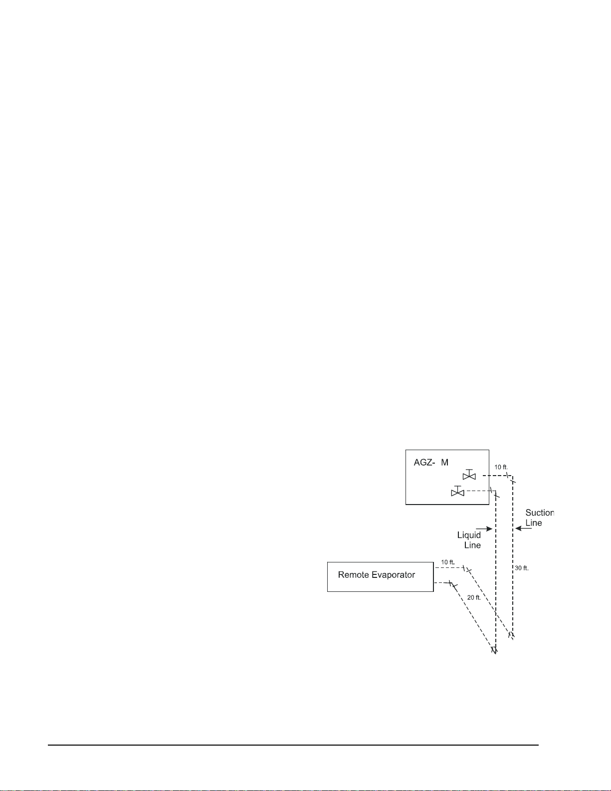
3. Determine the suction line size by first
summing the equivalent feet (from table 10) of
all the fittings (use a sketch of the piping
layout) and adding the sum of these fitting
Figure 6, Sample Piping Layout
B
losses to the actual linear feet of tubing. This
will equal the total equivalent feet. (To use the
equivalent feet table 10, start with the unit
suction connection size from table 13 and
correct if required.)
4. If the unit rated capacity in the tables is less
than the corrected required capacity, redo the
selection with the next larger unit. In most
cases the line size will be the unit connection
size. If the selection is satisfactory, correct the
power (if applicable) and determine water
pressure drop.
18 Catalog ACZ-AGZB1-1
Page 19

Selection example
English Units
Given:
20 tons required capacity
95°F ambient temperature
Cool 48 gpm from 54F to 44°F
0.0001 evaporator fouling factor
2,000 foot altitude
1. Add 3% to the required capacity for approximate derate: 20 x 1.03 = 20.6 tons. From
020B at the given conditions will produce 21.5 tons with a unit kW input of 29.0 and a unit EER of 8.9.
2. Determine derate factors:
Altitude correction from
Table 9:
0.998 Capacity, 1.009 Power
3. Piping correction:
Assume 1 5/8” suction line based on line size in
Table 13.
(3) 90 Standard ells 3 x 4 ft =12 ft
Plus actual linear feet 70 ft
Total Equivalent Feet 82 ft
This puts it between 1 5/8” and 2 1/8” line size.
Check
Table 11 and find that 1 5/8” is maximum size for oil carry.
This means that the 1 5/8 riser will be satisfactory, but with a slightly higher pressure drop.
The capacity correction factor from
Table 14 is between 0.97 and 0.98. Use 0.975.
4. The corrected capacity of the AGZ is: 21.5 tons x 0.998{altitude} x 0.98{piping} = 21.0 tons This satisfies
the 20 ton requirement.
5. Correct the unit power required: 29.0 kW x 1.009{altitude} = 29.3 kW.
6. Calculate the unit EER based on the correct capacity and power:
EER = (21 tons x 12,000)/ (29.3 kW x 1,000) = 8.6
7. Determine the evaporator pressure drop. Enter the pressure drop curves, (
Figure 7) at 48 gpm and read up to
AGZ 020, read over to pressure drop of 5.9 ft.
Table 16 an AGZ-
Selection example, SI Units
The selection procedure for Metric units is identical to English except that metric data and tables are used.
Catalog ACZ-AGZB1-1
19
Page 20
Application Adjustment Factors
Ethylene and Propylene Glycol Factors
AGZ units can operate with a leaving chilled fluid temperature range of 20°F (-6°C) to 60°F (10°C). A
glycol solution is required when leaving chilled fluid temperature is below 40°F (4.6°C). The use of glycol
will reduce the performance of the unit depending on concentration.
Altitude Correction Factors
Performance tables are based at sea level. Elevations other than sea level affect the performance of the unit.
The decreased air density will reduce condenser capacity consequently reducing the unit's performance. For
performance at elevations other than sea level refer to
Evaporator Temperature Drop Factors
Performance tables are based on a 10°F (5°C) temperature drop through the evaporator. Adjustment factors
for applications with temperature ranges from 6°F to 16°F (3.3°C to 8.9°C) are in Table 3. Temperature
drops outside this 6°F to 16°F (3.3°C to 8.9°C) range can affect the control system's capability to maintain
acceptable control and are not recommended.
The maximum water temperature that can be circulated through the evaporator in a non-operating mode is
100°F (37.8°C).
Table 7, Ethylene Glycol Factors
% E.G.
10
20
30
40
50
Freeze Point
°F °C
26 -3.3 0.998 0.998 1.036 1.097
18 -7.8 0.993 0.997 1.060 1.226
7 -13.9 0.987 0.995 1.092 1.369
-7 -21.7 0.980 0.992 1.132 1.557
-28 -33.3 0.973 0.991 1.182 1.791
Capacity Power Flow PD
Table 9.
Table 8, Propylene Glycol Factors
% P.G.
10
20
30
40
50
NOTE: Ethylene and propylene glycol ratings are outside the scope of ARI Standard 550/590-2003 certification program.
Freeze Point
°F °C
26 -3.3 0.995 0.997 1.016 1.100
19 -7.2 0.987 0.995 1.032 1.211
9 -12.8 0.978 0.992 1.057 1.380
-5 -20.6 0.964 0.987 1.092 1.703
-27 -32.8 0.952 0.983 1.140 2.251
Capacity Power Flow PD
20 Catalog ACZ-AGZB1-1
Page 21
Fouling Factor
Performance tables are based on water with a fouling factor of
As fouling is increased, performance decreases. For performance at other than 0.0001 (0.0176) fouling factor
refer to
Table 9. Foreign matter in the chilled water system will adversely affect the heat transfer capability of
the evaporator and could increase the pressure drop and reduce the water flow. Maintain proper water
treatment to provide optimum unit operation.
Table 9, Capacity and Power Derates
Chilled Water
Altitude
Sea
Level
2000 feet
4000 feet
6000 feet
Delta T
°F °C Cap. Power Cap. Power Cap. Power Cap. Power
6 3.3 0.978 0.993 0.975 0.991 0.963 0.987 0.940 0.980
8 4.4 0.989 0.996 0.986 0.994 0.973 0.990 0.950 0.983
10 5.6 1.000 1.000 0.996 0.999 0.984 0.994 0.961 0.987
12 6.7 1.009 1.003 1.005 1.001 0.993 0.997 0.969 0.990
14 7.7 1.018 1.004 1.014 1.003 1.002 0.999 0.978 0.991
16 8.9 1.025 1.007 1.021 1.006 1.009 1.001 0.985 0.994
6 3.3 0.977 1.001 0.973 1.000 0.961 0.996 0.938 0.989
8 4.4 0.987 1.006 0.984 1.004 0.971 1.000 0.948 0.993
10 5.6 0.998 1.009 0.995 1.007 0.982 1.003 0.959 0.996
12 6.7 1.007 1.011 1.004 1.010 0.991 1.006 0.967 0.998
14 7.7 1.014 1.014 1.011 1.013 0.998 1.009 0.974 1.001
16 8.9 1.022 1.016 1.018 1.014 1.005 1.010 0.981 1.003
6 3.3 0.973 1.011 0.970 1.010 0.957 1.006 0.935 0.998
8 4.4 0.984 1.014 0.980 1.013 0.968 1.009 0.945 1.001
10 5.6 0.995 1.019 0.991 1.017 0.979 1.013 0.955 1.005
12 6.7 1.004 1.021 1.000 1.020 0.987 1.016 0.964 1.008
14 7.7 1.011 1.024 1.007 1.023 0.994 1.018 0.971 1.011
16 8.9 1.018 1.027 1.014 1.026 1.002 1.021 0.978 1.014
6 3.3 0.969 1.021 0.966 1.020 0.954 1.016 0.931 1.008
8 4.4 0.980 1.026 0.977 1.024 0.964 1.020 0.942 1.013
10 5.6 0.989 1.029 0.986 1.027 0.973 1.023 0.950 1.015
12 6.7 0.998 1.033 0.995 1.031 0.982 1.027 0.959 1.020
14 7.7 1.007 1.036 1.004 1.034 0.991 1.030 0.967 1.022
16 8.9 1.014 1.037 1.011 1.036 0.998 1.031 0.974 1.024
0.0001 (0.0176) 0.00025 (0.044) 0.00075 (0.132) 0.00175 (0.308)
22
)/0176.0(/0001.0
kWCmorBTUFhrft per ARI 550/590-2003.
Fouling Factor
Table 10, Equivalent Feet for Fittings
Fitting Type 7/8 1 1/8 1 3/8 1 5/8 2 1/8 2 5/8 3 1/8
Elbows
90 Standard
90 Long Radius
90 Street
45 Standard
45 Street
180 Bend
Tees
Full Size
Reducing
Valves
Globe Valve, Open
Gate Valve, Open
Angle Valve, Open
2.0 2.6 3.3 4.0 5.0 6.0 7.5
1.4 1.7 2.3 2.6 3.3 4.1 5.0
3.2 4.1 5.6 6.3 8.2 10 12
0.9 1.3 1.7 2.1 2.6 3.2 4.0
1.5 2.1 3.0 3.4 4.5 5.2 6.4
3.2 4.1 5.6 6.3 8.2 10 12
1.4 1.7 2.3 2.6 3.3 4.1 5.0
2.0 2.6 3.3 4.0 5.0 6.0 7.5
22 29 38 43 55 69 84
0.9 1.0 1.5 1.8 2.3 2.8 3.2
9.0 12 15 18 24 29 35
Table 11, Maximum Line Size (R-22,R-407C) For Oil Carry Up a Suction Riser
Unit Size AGZ AGZ AGZ AGZ AG Z AGZ AGZ
Catalog ACZ-AGZB1-1
21
Page 22
010 013 017 020 025 029 034
Line Size 1 1/8 1 3/8 1 5/8 1 5/8 1 5/8 2 1/8 2 1/8
Table 12, Recommended Liquid Line Size, R-22, R-407C
AGZ-BM
Unit Model
AGZ 01
AGZ 013
AGZ 016
AGZ 020
AGZ 025
AGZ 029
AGZ 034
Connection
Size
At Unit
7/8" 7/8 " 7/8 " 7/8 " 7/8 " 7/8 "
7/8" 7/8 " 7/8 " 7/8 " 7/8 " 7/8 "
7/8" 7/8 " 7/8 " 7/8 " 7/8 " 7/8 "
7/8" 7/8 " 7/8 " 7/8 " 7/8 "
7/8" 7/8 " 7/8 " 7/8 "
7/8" 7/8 " 7/8 "
7/8" 7/8 "
Up to Up to Up to Up to Up to
50 Equiv. Ft 75 Equiv. Ft 100 Equiv. Ft 125 Equiv. Ft 150 Equiv. Ft
Recommended Liquid Line Size
1 1/8 " 1 1/8 " 1 1/8 "
1 1/8 " 1 1/8 " 1 1/8 " 1 1/8 "
Table 13, Recommended Suction Line Size, R-22, R-407C
Unit Model
AGZ 010AM
AGZ 013AM
AGZ 016AM
AGZ 020AM
AGZ 025AM
AGZ 029AM
AGZ 034AM
Note: For horizontal and vertical downflow only.
Connection
Size
At Unit
1 1/8”
1 1/8” 1 3/8"
1 5/8"
1 5/8"
1 5/8"
2 1/8" 2 1/8" 2 1/8" 2 1/8" 2 1/8"
2 1/8" 2 1/8" 2 1/8"
Up to Up to Up to Up to Up to
50 Equiv. Ft 75 Equiv. Ft 100 Equiv. Ft 125 Equiv. Ft 150 Equiv. Ft
1 1/8”
1 5/8" 1 5/8" 1 5/8"
1 5/8" 1 5/8"
1 5/8"
Recommended Suction Line Sizes
1 3/8" 1 3/8"
1 5/8" 1 5/8" 1 5/8" 1 5/8"
2 1/8" 2 1/8" 2 1/8"
2 1/8" 2 1/8" 2 1/8" 2 1/8"
2 5/8" 2 5/8" 2 5/8"
1 1/8 "
1 1/8 " 1 1/8 "
1 5/8" 1 5/8"
2 1/8" 2 1/8"
2 5/8"
Table 14, Refrigerant Piping Derates
Unit Capacity Loss Factor Due to Refrigerant Piping
Model At Unit 50 Equiv. Ft 75 Equiv. Ft 100 Equiv. Ft 125 Equiv. Ft 150 Equiv. Ft
AGZ 010AM
AGZ 013AM
AGZ 016AM
AGZ 020AM
AGZ 025AM
AGZ 029AM
AGZ 034AM
1.0 0.98 0.98 0.97
1.0 0.98
1.0
1.0
1.0
1.0 0.99 0.98 0.97 0.96
1.0 0.99 0.98
0.99 0.98 0.98
0.98 0.97
0.98
0.98 0.98 0.97 0.96
0.98 0.98 0.97
0.99 0.99 0.98 0.97
0.98 0.97 0.97
0.98 0.97
0.99 0.98
0.98
22 Catalog ACZ-AGZB1-1
Page 23

AGZ Chiller Performance Data
I-P Units
Table 15, Performance Data, R-22, I-P Units, 60 Hz
AGZ
NOTES:
1. Ratings in accordance with ARI Standard 550/590-2003. Bold ratings are at ARI standard conditions.
2. Ratings based on R-22, evap. fouling factor of 0.0001, evaporator water flow of 2.4 gpm/ton and sea level altitude.
3. KW input is for the entire unit including compressors, fan motors and control power.
4. Interpolation is allowed; extrapolation is not permitted. Consult McQuay for performance outside the cataloged ratings.
5. For LWT below 40°F please refer to Application Considerations section.
Fan &
Control
Unit
Power
Size
010 2.3
013 2.3
017 2.3
020 3.2
025 3.2
029 3.2
034 3.2
(kW)
LWT
(F)
Tons
40 10.0 10.3 11.6 9.6 11.2 10.2 9.2 12.2 9.1 8.8 13.4 7.9 8.3 14.6 6.8
42 10.4 10.4 12.0 10.0 11.3 10.6 9.6 12.3 9.4 9.1 13.4 8.1 8.6 14.7 7.0
44 10.8 10.5 12.3 10.4 11.3 11.0
46 11.3 10.6 12.8 10.8 11.5 11.3 10.4 12.5 10.0 9.9 13.6 8.7 9.4 14.9 7.5
48 11.7 10.7 13.1 11.2 11.6 11.7 10.8 12.6 10.3 10.3 13.7 9.0 9.7 15.0 7.7
50 12.1 10.8 13.4 11.6 11.7 12.0 11.2 12.7 10.6 10.7 13.8 9.3 10.1 15.1 8.0
40 13.9 14.3 11.7 13.3 15.5 10.3 12.7 16.8 9.0 12.1 18.4 7.9 11.4 20.0 6.9
42 14.4 14.4 12.1 13.8 15.6 10.6 13.2 16.9 9.4 12.6 18.5 8.2 11.8 20.2 7.0
44 14.9 14.5 12.4 14.3 15.7 11.0
46 15.6 14.7 12.7 14.8 15.9 11.2 14.2 17.2 9.9 13.5 18.8 8.6 12.8 20.5 7.5
48 16.1 14.8 13.1 15.5 16.0 11.6 14.7 17.4 10.1 14.0 19.0 8.9 13.2 20.6 7.7
50 16.7 14.9 13.5 16.0 16.1 11.9 15.2 17.5 10.4 14.5 19.1 9.1 13.7 20.8 7.9
40 16.1 16.3 11.9 15.4 17.8 10.4 14.7 19.5 9.1 13.9 21.1 7.9 13.1 23.1 6.8
42 16.7 16.5 12.2 16.0 18.0 10.7 15.2 19.6 9.3 14.4 21.3 8.1 13.6 23.3 7.0
44 17.3 16.6 12.5 16.6 18.1 11.0
46 18.0 16.8 12.9 17.2 18.3 11.3 16.3 19.8 9.9 15.5 21.7 8.6 14.6 23.6 7.4
48 18.6 17.0 13.2 17.8 18.5 11.6 16.9 20.0 10.1 16.0 21.8 8.8 15.1 23.8 7.6
50 19.2 17.1 13.5 18.4 18.6 11.9 17.5 20.2 10.4 16.6 22.0 9.0 15.6 24.0 7.8
40 21.0 21.5 11.7 20.1 23.3 10.3 19.2 25.3 9.1 18.2 27.6 7.9 17.1 30.0 6.8
42 21.7 21.7 12.0 20.8 23.5 10.6 19.9 25.5 9.3 18.8 27.8 8.1 17.7 30.3 7.0
44 22.5 21.9 12.3 21.6 23.7 10.9
46 23.3 22.1 12.7 22.3 23.9 11.2 21.3 26.0 9.9 20.2 28.3 8.6 19.1 30.7 7.5
48 24.1 22.3 13.0 23.1 24.1 11.5 22.1 26.2 10.1 20.9 28.5 8.8 19.7 31.0 7.6
50 25.0 22.5 13.4 23.9 24.3 11.8 22.8 26.5 10.4 21.7 28.7 9.1 20.4 31.2 7.8
40 23.1 23.7 11.7 22.2 25.7 10.4 21.1 27.9 9.1 19.9 30.3 7.9 18.7 33.0 6.8
42 24.0 24.0 12.0 23.0 25.9 10.7 21.9 28.1 9.4 20.7 30.6 8.1 19.4 33.3 7.0
44 24.9 24.2 12.4 23.8 26.2 10.9
46 26.0 24.2 12.9 24.7 26.5 11.2 23.5 28.7 9.8 22.2 31.2 8.5 20.9 33.9 7.4
48 26.7 24.8 12.9 25.6 26.7 11.5 24.3 29.0 10.1 23.0 31.5 8.8 21.6 34.2 7.6
50 27.7 25.1 13.3 26.5 27.0 11.8 25.2 29.3 10.3 23.8 31.8 9.0 22.4 34.5 7.8
40 28.2 28.4 11.9 27.0 31.1 10.4 25.8 34.1 9.1 24.5 37.2 7.9 23.1 40.7 6.8
42 29.3 28.7 12.3 28.0 31.4 10.7 26.8 34.4 9.3 25.4 37.6 8.1 23.9 41.1 7.0
44 30.4 29.0 12.6 29.1 31.7 11.0
46 31.5 29.3 12.9 30.1 32.0 11.3 28.7 35.0 9.9 27.2 38.3 8.5 25.7 41.9 7.4
48 32.6 29.7 13.2 31.2 32.3 11.6 29.7 35.4 10.1 28.2 38.6 8.8 26.7 42.2 7.6
50 33.7 30.0 13.5 32.2 32.7 11.8 30.8 35.7 10.3 29.2 39.0 9.0 27.5 42.6 7.8
40 34.9 35.0 12.0 33.4 38.2 10.5 31.7 41.6 9.1 29.9 45.2 7.9 27.9 49.1 6.8
42 36.1 35.4 12.2 34.6 38.6 10.8 32.9 42.1 9.4 31.0 45.7 8.1 28.9 49.6 7.0
44 37.4 35.9 12.5 35.8 39.0 11.0
46 38.8 36.3 12.8 37.1 39.5 11.3 35.2 43.0 9.8 33.2 46.7 8.5 31.1 50.7 7.4
48 40.1 36.7 13.1 38.3 39.9 11.5 36.4 43.5 10.0 34.4 47.3 8.7 32.2 51.3 7.5
50 41.5 37.2 13.4 39.6 40.4 11.8 37.7 44.0 10.3 35.6 47.8 8.9 33.3 51.8 7.7
75 85 95 105 115
Unit
PWR
Unit
Unit
kWi
EER
Tons
PWR
kWi
Ambient Air Temperature (F)
Unit
Unit
PWR
EER
Tons
10.0 12.4 9.7
13.7 17.1 9.6
15.8 19.8 9.6
20.6 25.8 9.6
22.7 28.4 9.6
27.7 34.7 9.6
34.0 42.5 9.6
kWi
Unit
EER
Unit
PWR
Unit
Tons
kWi
9.5 13.5 8.4 9.0 14.8 7.3
13.0 18.7 8.3 12.3 20.3 7.2
14.9 21.5 8.3 14.1 23.5 7.2
19.5 28.0 8.4 18.4 30.5 7.2
21.4 30.9 8.3 20.1 33.6 7.2
26.3 37.9 8.3 24.8 41.5 7.2
32.1 46.2 8.3 30.0 50.2 7.2
EER
Unit
Tons
PWR
kWi
Unit
EER
Catalog ACZ-AGZB1-1
23
Page 24

Table 16, Performance Data, R-407C, I-P, 60 Hz
AGZ
Unit
Size
010 2.3
013 2.3
017 2.3
020 3.2
025 3.2
029 3.2
034 3.2
NOTES:
1. Ratings based on R-407C, evaporator fouling factor of 0.0001, evaporator water flow of 2.4 gpm/ton and sea level altitude.
2. KW input is for the entire unit including compressors, fan motors and control power.
3. Interpolation is allowed; extrapolation is not permitted. Consult McQuay for performance outside the cataloged ratings.
4. For LWT below 40°F please refer to Application Considerations.
5. Use anti-freeze below 42.0F.
Fan &
Control
Power
(kW)
LWT
(F)
Tons
42 10.2 10.8 11.4 9.8 11.7 10.1 9.4 12.8 8.8 9.0 14.1 7.7 8.5 15.4 6.6
44 10.7 10.9 11.8 10.2 11.8 10.4
46 11.1 11.0 12.2 10.7 11.9 10.8 10.2 13.0 9.4 9.7 14.3 8.2 9.3 15.7 7.1
48 11.5 11.1 12.5 11.1 12.0 11.1 10.6 13.1 9.7 10.1 14.4 8.4 9.6 15.8 7.3
50 12.0 11.1 13.0 11.5 12.1 11.4 11.0 13.2 10.0 10.5 14.5 8.7 10.0 15.9 7.5
42 14.0 14.7 11.5 13.5 16.0 10.1 12.9 17.5 8.9 12.3 19.2 7.7 11.7 21.0 6.7
44 14.6 14.9 11.8 14.0 16.2 10.4
46 15.2 14.9 12.2 14.5 16.3 10.7 13.9 17.8 9.4 13.3 19.5 8.2 12.6 21.4 7.1
48 15.7 15.1 12.4 15.2 16.5 11.0 14.4 18.0 9.6 13.7 19.8 8.3 13.1 21.6 7.3
50 16.3 15.2 12.8 15.7 16.6 11.3 15.0 18.1 9.9 14.2 19.9 8.6 13.5 21.7 7.5
42 16.2 17.0 11.4 15.6 18.5 10.1 14.9 20.2 8.8 14.2 22.1 7.7 13.5 24.3 6.7
44 16.9 17.1 11.8 16.2 18.7 10.4
46 17.4 17.2 12.1 16.7 18.7 10.7 16.0 20.5 9.3 15.3 22.5 8.1 14.5 24.6 7.1
48 18.0 17.4 12.4 17.4 18.9 11.0 16.6 20.7 9.6 15.8 22.7 8.3 15.0 24.9 7.2
50 18.6 17.0 13.1 17.9 18.5 11.6 17.2 20.2 10.2 16.4 22.1 8.9 15.6 24.3 7.7
42 21.2 22.2 11.5 20.4 24.2 10.1 19.5 26.4 8.9 18.6 28.9 7.7 17.7 31.7 6.7
44 22.0 22.4 11.8 21.1 24.4 10.4
46 22.7 22.5 12.1 21.9 24.5 10.7 20.9 26.8 9.3 19.9 29.4 8.1 18.9 32.2 7.0
48 23.6 22.8 12.4 22.7 24.8 11.0 21.7 27.1 9.6 20.7 29.7 8.4 19.7 32.6 7.2
50 24.4 23.1 12.7 23.4 25.1 11.2 22.4 27.5 9.8 21.4 30.1 8.5 20.3 33.0 7.4
42 23.3 24.4 11.5 22.4 26.5 10.2 21.5 29.0 8.9 20.5 31.7 7.7 19.5 34.9 6.7
44 24.2 24.6 11.8 23.2 26.8 10.4
46 25.1 25.0 12.1 24.1 27.1 10.7 23.0 29.6 9.3 21.9 32.5 8.1 20.9 35.6 7.0
48 25.9 25.2 12.4 24.9 27.5 10.9 23.8 30.0 9.5 22.7 32.8 8.3 21.6 36.0 7.2
50 27.0 25.5 12.7 26.0 27.7 11.3 24.8 30.3 9.8 23.6 33.2 8.5 22.4 36.3 7.4
42 28.5 29.9 11.5 27.4 32.4 10.1 26.2 35.5 8.9 25.0 38.7 7.8 23.8 42.6 6.7
44 29.6 30.1 11.8 28.4 32.8 10.4
46 30.7 30.5 12.1 29.4 33.2 10.6 28.1 36.2 9.3 26.9 39.6 8.1 25.5 43.5 7.0
48 31.6 30.7 12.4 30.5 33.5 10.9 29.1 36.6 9.5 27.8 40.0 8.3 26.4 44.0 7.2
50 32.7 31.1 12.6 31.4 33.8 11.2 30.1 37.0 9.8 28.7 40.5 8.5 27.3 44.4 7.4
42 35.1 37.4 11.3 33.7 40.6 10.0 32.2 44.4 8.7 30.7 48.6 7.6 29.2 53.4 6.6
44 36.3 37.7 11.5 34.9 41.1 10.2
46 37.5 38.2 11.8 36.0 41.5 10.4 34.4 45.4 9.1 32.8 49.7 7.9 31.1 54.6 6.9
48 38.8 38.5 12.1 37.3 42.0 10.6 35.6 45.9 9.3 33.9 50.2 8.1 32.2 55.2 7.0
50 40.1 39.0 12.4 38.6 42.3 10.9 36.9 46.4 9.5 35.2 50.8 8.3 33.4 55.7 7.2
75 85 95 105 115
Unit
PWR
Unit
Unit
kWi
EER
Tons
Ambient Air Temperature (F)
PWR
Unit
Unit
PWR
kWi
EER
Tons
kWi
9.8 12.9 9.1
13.4 17.7 9.1
15.5 20.4 9.1
20.2 26.6 9.1
22.2 29.3 9.1
27.2 35.8 9.1
33.3 44.9 8.9
Unit
Unit
PWR
Unit
Unit
EER
Tons
kWi
EER
Tons
9.4 14.2 8.0 8.9 15.5 6.9
12.8 19.4 7.9 12.2 21.2 6.9
14.8 22.3 8.0 14.0 24.5 6.9
19.3 29.2 7.9 18.3 32.0 6.9
21.3 32.2 7.9 20.2 35.2 6.9
25.9 39.2 7.9 24.7 43.0 6.9
31.7 49.2 7.7 30.2 53.9 6.7
PWR
kWi
Unit
EER
24 Catalog ACZ-AGZB1-1
Page 25

SI Units
Table 17, Performance Data, R-22, SI Units, 60 Hz
AGZ
Fan &
Unit
Control
Size
Power
(kW)
010 2.3
013 2.3
017 2.3
020 3.2
025 3.2
029 3.2
034 3.2
NOTES:
1. Ratings based on R-22, evaporator fouling factor of 0.0176, 5.6C evaporator delta-T, and sea level altitude.
2. KW input is for the entire unit including compressors, fan motors and control power.
3. Interpolation is allowed; extrapolation is not permitted. Consult McQuay for performance outside the cataloged ratings.
4. For LWT below 5.0°C please refer to Application Considerations.
5. Use anti-freeze below 6.0C.
LWT
(C)
5.0 35.4 10.4 3.4 34.1 11.3 3.0 32.6 12.2 2.7 31.2 13.2 2.4 29.7 14.3 2.1
6.0 36.6 10.5 3.5 35.3 11.4 3.1 33.9 12.3 2.8 32.4 13.3 2.4 30.8 14.4 2.1
7.0 37.9 10.6 3.6 36.6 11.5 3.2
8.0 39.3 10.7 3.7 37.9 11.6 3.3 36.4 12.4 2.9 34.9 13.4 2.6 33.1 14.6 2.3
9.0 40.6 10.9 3.8 39.2 11.6 3.4 37.7 12.5 3.0 36.1 13.5 2.7 34.4 14.7 2.3
10.0 42.0 10.9 3.8 40.5 11.7 3.5 39.0 12.6 3.1 37.3 13.6 2.7 35.6 14.8 2.4
5.0 48.8 14.6 3.4 46.9 15.7 3.0 45.0 16.9 2.7 43.1 18.3 2.4 41.0 19.8 2.1
6.0 50.4 14.7 3.4 48.5 15.8 3.1 46.6 17.0 2.7 44.5 18.4 2.4 42.3 19.9 2.1
7.0 52.2 14.8 3.5 50.1 15.9 3.2
8.0 53.9 14.9 3.6 51.9 16.0 3.2 49.8 17.2 2.9 47.6 18.7 2.6 45.2 20.2 2.2
9.0 55.6 15.1 3.7 53.6 16.1 3.3 51.4 17.4 3.0 49.2 18.8 2.6 46.7 20.3 2.3
10.0 57.5 15.2 3.8 55.3 16.3 3.4 53.2 17.5 3.0 50.8 19.0 2.7 48.2 20.4 2.4
5.0 56.8 16.7 3.4 54.5 18.1 3.0 52.1 19.5 2.7 49.7 21.1 2.4 47.2 22.8 2.1
6.0 58.6 16.8 3.5 56.3 18.2 3.1 53.8 19.7 2.8 51.3 21.2 2.4 48.7 22.9 2.1
7.0 60.5 17.0 3.6 58.1 18.3 3.2
8.0 62.5 17.1 3.7 59.9 18.5 3.3 57.3 19.9 2.9 54.7 21.5 2.5 51.9 23.3 2.2
9.0 64.3 17.3 3.8 61.8 18.6 3.3 59.1 20.0 3.0 56.4 21.7 2.6 53.5 23.5 2.3
10.0 66.3 17.4 3.8 63.6 18.8 3.4 60.9 20.2 3.0 58.1 21.8 2.7 55.2 23.6 2.3
5.0 73.9 21.8 3.4 70.9 23.5 3.0 67.9 25.3 2.7 64.7 27.4 2.4 61.3 29.6 2.1
6.0 76.3 22.0 3.5 73.3 23.7 3.1 70.2 25.5 2.8 66.9 27.6 2.4 63.4 29.8 2.1
7.0 78.7 22.2 3.5 75.7 23.8 3.2
8.0 81.3 22.4 3.6 78.1 24.0 3.2 74.9 26.0 2.9 71.3 28.0 2.6 67.6 30.2 2.2
9.0 83.8 22.6 3.7 80.6 24.2 3.3 77.2 26.2 3.0 73.7 28.2 2.6 69.8 30.4 2.3
10.0 86.5 22.8 3.8 83.1 24.4 3.4 79.6 26.4 3.0 76.0 28.4 2.7 72.0 30.6 2.4
5.0 81.4 24.2 3.4 78.3 25.9 3.0 74.8 27.9 2.7 71.1 30.1 2.4 67.2 32.5 2.1
6.0 84.1 24.4 3.5 80.8 26.2 3.1 77.3 28.2 2.7 73.5 30.4 2.4 69.4 32.8 2.1
7.0 87.1 24.5 3.6 83.4 26.4 3.2
8.0 90.1 24.7 3.7 86.2 26.6 3.2 82.4 28.6 2.9 78.4 30.9 2.5 74.2 33.3 2.2
9.0 92.6 25.1 3.7 88.9 26.9 3.3 85.1 28.9 2.9 80.9 31.1 2.6 76.6 33.6 2.3
10.0 95.6 25.4 3.8 91.7 27.1 3.4 87.8 29.2 3.0 83.5 31.4 2.7 79.0 33.9 2.3
5.0 99.4 29.0 3.4 95.5 31.4 3.0 91.4 34.1 2.7 87.3 37.0 2.4 82.9 40.0 2.1
6.0 102.7 29.3 3.5 98.6 31.7 3.1 94.4 34.4 2.7 90.2 37.3 2.4 85.6 40.4 2.1
7.0 106.0 29.6 3.6 101.8 32.0 3.2
8.0 109.5 29.8 3.7 105.1 32.3 3.3 100.6 35.0 2.9 96.1 37.9 2.5 91.2 41.0 2.2
9.0 112.9 30.1 3.8 108.5 32.6 3.3 103.9 35.3 2.9 99.1 38.2 2.6 94.1 41.4 2.3
10.0 116.5 30.4 3.8 111.9 32.9 3.4 107.1 35.6 3.0 102.2 38.6 2.6 97.1 41.7 2.3
5.0 122.4 36.5 3.4 117.5 39.3 3.0 112.3 42.5 2.6 106.5 45.8 2.3 100.3 49.4 2.0
6.0 126.4 36.8 3.4 121.4 39.7 3.1 115.9 42.9 2.7 110.0 46.4 2.4 103.6 49.9 2.1
7.0 130.5 37.2 3.5 125.2 40.2 3.1
8.0 134.5 37.6 3.6 129.2 40.6 3.2 123.3 43.8 2.8 117.1 47.3 2.5 110.4 50.8 2.2
9.0 138.8 38.0 3.7 133.1 41.0 3.3 127.2 44.2 2.9 120.8 47.7 2.5 113.8 51.3 2.2
10.0 143.0 38.4 3.7 137.2 41.5 3.3 131.1 44.7 2.9 124.4 48.2 2.6 117.4 51.8 2.3
25 30 35 40 45
Unit
PWR
Unit
Unit
PWR
kW
kWi
COP
kW
kWi
Ambient Air Temperature (C)
Unit
Unit
PWR
Unit
COP
kW
kWi
COP
35.2 12.4 2.8
48.2 17.1 2.8
55.6 19.8 2.8
72.5 25.8 2.8
79.8 28.4 2.8
97.5 34.7 2.8
119.6 43.4 2.8
Unit
PWR
Unit
Unit
kW
kWi
COP
kW
33.7 13.4 2.5 32.0 14.5 2.2
46.0 18.6 2.5 43.7 20.0 2.2
53.0 21.4 2.5 50.2 23.1 2.2
69.1 27.8 2.5 65.5 30.0 2.2
75.9 30.6 2.5 71.8 33.0 2.2
93.1 37.6 2.5 88.4 40.7 2.2
113.5 46.8 2.4 106.9 50.3 2.1
PWR
kWi
Unit
COP
Catalog ACZ-AGZB1-1
25
Page 26

Table 18, Performance Data, R-407C, SI Units, 60 Hz
Fan &
AGZ
Control
Unit
Power
Size
(kW)
010 2.3
013 2.3
017 2.3
020 3.2
025 3.2
029 3.2
034 3.2
NOTES:
1. Ratings based on R-407C, evaporator fouling factor of 0.0176, 5.6C evaporator delta-T, and sea level altitude.
2. KW input is for the entire unit including compressors, fan motors and control power.
3. Interpolation is allowed; extrapolation is not permitted. Consult McQuay for performance outside the cataloged ratings.
4. For LWT below 5.0°C please refer to Application Considerations.
LWT
(C)
6.0 35.9 10.8 3.3 34.7 11.7 3.0 33.2 12.8 2.6 31.9 14.1 2.3 30.6 15.4 2.0
7.0 37.3 10.9 3.4 35.9 11.8 3.0
8.0 38.7 11.0 3.5 37.4 11.9 3.1 35.8 13.0 2.7 34.4 14.3 2.4 32.9 15.7 2.1
9.0 40.0 11.1 3.6 38.7 12.0 3.2 37.2 13.1 2.8 35.6 14.4 2.5 34.0 15.8 2.1
10.0 41.5 11.1 3.7 40.1 12.1 3.3 38.4 13.2 2.9 36.8 14.5 2.5 35.3 15.9 2.2
6.0 49.2 14.7 3.3 47.5 16.0 3.0 45.6 17.5 2.6 43.8 19.2 2.3 41.9 21.0 2.0
7.0 50.9 14.9 3.4 49.1 16.2 3.0
8.0 52.8 14.9 3.5 50.9 16.3 3.1 48.8 17.8 2.7 46.8 19.5 2.4 44.8 21.4 2.1
9.0 54.4 15.1 3.6 52.6 16.5 3.2 50.5 18.0 2.8 48.3 19.8 2.4 46.2 21.6 2.1
10.0 56.2 15.2 3.7 54.3 16.6 3.3 52.1 18.1 2.9 49.9 19.9 2.5 47.7 21.7 2.2
6.0 56.7 17.0 3.3 54.8 18.5 3.0 52.5 20.2 2.6 50.5 22.1 2.3 48.3 24.3 2.0
7.0 58.8 17.1 3.4 56.6 18.7 3.0
8.0 60.4 17.2 3.5 58.4 18.7 3.1 55.9 20.5 2.7 53.7 22.5 2.4 51.4 24.6 2.1
9.0 62.3 17.4 3.6 60.3 18.9 3.2 58.0 20.7 2.8 55.4 22.7 2.4 53.0 24.9 2.1
10.0 64.4 17.0 3.8 62.3 18.5 3.4 59.7 20.2 3.0 57.3 22.1 2.6 54.8 24.3 2.3
6.0 74.4 22.2 3.4 71.8 24.2 3.0 68.8 26.4 2.6 66.0 28.9 2.3 63.3 31.7 2.0
7.0 76.6 22.4 3.4 73.9 24.4 3.0
8.0 79.1 22.5 3.5 76.3 24.5 3.1 73.3 26.8 2.7 70.3 29.4 2.4 67.2 32.2 2.1
9.0 81.6 22.8 3.6 79.0 24.8 3.2 76.0 27.1 2.8 72.7 29.7 2.4 69.4 32.6 2.1
10.0 84.2 23.0 3.7 81.3 25.1 3.2 78.0 27.5 2.8 74.8 30.1 2.5 71.6 33.0 2.2
6.0 81.8 24.4 3.3 78.9 26.5 3.0 75.7 29.0 2.6 72.8 31.7 2.3 69.6 34.9 2.0
7.0 84.4 24.6 3.4 81.4 26.8 3.0
8.0 87.2 25.0 3.5 84.2 27.1 3.1 80.8 29.6 2.7 77.6 32.5 2.4 74.1 35.6 2.1
9.0 89.7 25.2 3.6 86.8 27.5 3.2 83.4 30.0 2.8 79.8 32.8 2.4 76.3 36.0 2.1
10.0 93.3 25.5 3.7 90.1 27.7 3.3 86.5 30.3 2.9 82.8 33.2 2.5 79.3 36.3 2.2
6.0 99.9 29.8 3.4 96.5 32.6 3.0 92.5 35.5 2.6 88.9 38.9 2.3 85.0 42.7 2.0
7.0 103.2 30.1 3.4 99.4 32.8 3.0
8.0 106.6 30.4 3.5 102.9 33.2 3.1 98.7 36.2 2.7 94.7 39.7 2.4 90.7 43.5 2.1
9.0 109.6 30.8 3.6 106.1 33.6 3.2 102.0 36.7 2.8 97.6 40.1 2.4 93.2 44.0 2.1
10.0 113.1 31.0 3.6 109.3 33.8 3.2 104.8 37.0 2.8 100.5 40.4 2.5 96.2 44.4 2.2
6.0 122.9 37.9 3.2 118.6 41.3 2.9 113.8 45.1 2.5 109.3 49.4 2.2 104.6 54.2 1.9
7.0 126.5 37.7 3.4 121.9 41.1 3.0
8.0 130.2 38.7 3.4 125.7 42.2 3.0 120.6 46.1 2.6 115.7 50.5 2.3 110.7 55.4 2.0
9.0 133.9 39.2 3.4 129.6 42.6 3.0 124.6 46.6 2.7 119.1 51.0 2.3 113.9 56.0 2.0
10.0 138.6 39.6 3.5 133.9 43.1 3.1 128.4 47.1 2.7 123.2 51.6 2.4 117.9 56.6 2.1
25 30 35 40 45
Unit
PWR
Unit
Unit
PWR
kW
kWi
COP
kW
kWi
Ambient Air Temperature (C)
Unit
Unit
PWR
Unit
COP
kW
kWi
COP
34.5 12.9 2.7
47.2 17.7 2.7
54.5 20.4 2.7
71.0 26.6 2.7
78.2 29.3 2.7
95.6 35.8 2.7
117.2 44.9 2.6
Unit
PWR
Unit
Unit
kW
kWi
COP
kW
33.2 14.2 2.3 31.7 15.5 2.0
45.4 19.4 2.3 43.4 21.2 2.0
52.3 22.3 2.3 50.0 24.5 2.0
68.3 29.2 2.3 65.3 32.0 2.0
75.2 32.2 2.3 71.9 35.2 2.0
91.9 39.2 2.3 87.9 43.0 2.0
112.6 49.2 2.3 107.6 53.9 2.0
PWR
kWi
Unit
COP
26 Catalog ACZ-AGZB1-1
Page 27

AGZ Part Load Data
Table 19, R-22 and R-407C, IP Units, 60Hz
R-22
AGZ
Unit
% Load
Size
100.0 10.0 12.4 9.7 100.0 9.8 12.9 9.1
010
100.0 13.7 17.1 9.6 100.0 13.4 17.7 9.1
013
100.0 15.8 19.8 9.6 100.0 15.5 20.4 9.1
017
100.0 20.6 25.8 9.6 100.0 20.2 26.6 9.1
020
100.0 22.7 28.4 9.6 100.0 22.2 29.3 9.1
025
100.0 27.7 34.7 9.6 100.0 27.2 35.8 9.1
029
100.0 34.0 43.4 9.4 100.0 33.3 44.9 8.9
034
NOTE: Certified according to ARI Standard 550/590-2003.
Capacity
Tons
75.0 7.5 7.6 11.9 75.0 7.4 7.4 11.9
50.0 5.0 4.3 14.0 50.0 4.9 4.2 14.0
25.0 2.5 2.0 15.0
75.0 10.3 10.3 12.0 75.0 10.1 10.1 12.0
50.0 6.9 5.8 14.1 50.0 6.7 5.7 14.1
25.0 3.4 2.7 15.1
75.0 11.9 11.8 12.1 75.0 11.6 11.5 12.1
50.0 7.9 6.6 14.3 50.0 7.7 6.5 14.3
25.0 4.0 3.1 15.3
75.0 15.5 14.8 12.5 75.0 15.1 14.5 12.5
50.0 10.3 8.2 15.0 50.0 10.1 8.1 15.0
25.0 5.2 3.9 16.0
75.0 17.0 16.3 12.5 75.0 16.7 16.0 12.5
50.0 11.4 9.1 15.0 50.0 11.1 8.9 15.0
25.0 5.7 4.3 16.0
75.0 20.8 20.1 12.4 75.0 20.4 19.7 12.4
50.0 13.9 11.5 14.5 50.0 13.6 11.2 14.5
25.0 6.9 5.4 15.5
75.0 25.5 25.1 12.2 75.0 25.0 24.6 12.2
50.0 17.0 14.2 14.4 50.0 16.7 13.9 14.4
25.0 8.5 6.7 15.2
Power
kWi
EER IPLV
13.2
13.3
13.4
14.0
14.0
13.7
13.5
AGZ
Unit
Size
010
013
017
020
025
029
034
R-407C
% Load
Capacity
Tons
25.0 2.5 2.0 15.0
25.0 3.4 2.7 15.1
25.0 3.9 3.0 15.3
25.0 5.0 3.8 16.0
25.0 5.6 4.2 16.0
25.0 6.8 5.3 15.5
25.0 8.3 6.6 15.2
Power
kWi
EER IPLV
13.2
13.3
13.4
14.0
14.0
13.7
13.5
Catalog ACZ-AGZB1-1
27
Page 28

A
A
A
A
Pressure Drop Curves
Figure 7, AGZ 010B – 034B, Evaporator Pressure Drops
AGZ 010
GZ 020
GZ 025
GZ 029
GZ 034
AGZ 017
AGZ 013
AGZ Unit
Model
AGZ 010B
AGZ 013B
AGZ 017B
AGZ 020B
AGZ 025B
AGZ 029B
AGZ 034B
Inch-Pound S.I. Inch-Pound S.I. Inch-Pound S.I.
gpm DP ft. lps DP kpa gpm DP ft. lps DP kpa gpm DP ft. lps DP kpa
15 2.3 0.9 6.9 24 5.7 1.5 17.0 39 14.8 2.5 44.1
20 1.6 1.3 4.8 32 4.0 2.0 11.9 53 10.5 3.3 31.3
24 1.7 1.5 5.1 38 4.3 2.4 12.8 64 11.2 4.0 33.4
31 2.6 1.9 7.7 49 6.2 3.1 18.5 82 16.3 5.2 48.6
34 2.0 2.2 6.0 55 4.8 3.5 14.3 91 12.7 5.7 37.8
43 2.2 2.7 6.6 68 5.3 4.3 15.8 113 14.1 7.1 42.0
51 2.2 3.2 6.6 82 5.3 5.2 15.8 136 14.2 8.6 42.3
Minimum Nominal Maximum
28 Catalog ACZ-AGZB1-1
Page 29

Sound Data
AGZ/ACZ Units
Table 20, Sound Pressure, w/o Sound Insulation
Model
-- 010B
010B 013B
013B 016B
017B 020B
020B 025B
025B 028B
029B 033B
034B 039B
Note: Data at:
1. 30 feet (9m) from side of unit.
2. Q=2, unit on a flat roof or ground with no adjacent wall.
3. Octave band readings are flat dB, overall is “A” weighted.
ACZ Unit
Model
63 125 250 500 1000 2000 4000 8000
52 52 52 54 48 46 44 42 55
52 52 52 54 48 46 44 42 55
53 54 54 55 48 47 45 42 56
58 56 55 53 52 50 48 48 57
58 57 56 54 52 50 48 48 58
58 58 56 55 52 50 48 48 58
59 59 61 58 54 53 51 50 61
61 62 63 59 55 54 53 51 63
Table 21, Sound Power, w/o Sound Insulation
Model
-- 010B
010B 013B
013B 016B
017B 020B
020B 025B
025B 028B
029B 033B
034B 039B
Note: Octave band readings are flat dB, overall is “A” weighted.
ACZ Unit
Model
Octave Band at Center Frequency (per ARI Standard 370) AGZ Unit
63 125 250 500 1000 2000 4000 8000
79 79 79 81 75 73 71 69 82
79 79 79 81 75 73 71 69 82
80 81 81 82 75 74 72 69 83
85 83 82 80 79 77 75 75 84
85 84 83 81 79 77 75 75 85
85 85 83 82 79 77 75 75 85
86 86 88 85 81 80 78 77 88
88 89 90 86 82 81 80 78 90
Octave Band at Center Frequency AGZ Unit
Overall
A-Weighted
Overall
A-Weighted
Table 22, Sound Pressure w/ Sound Insulation
Model
-- 010B
010B 013B
013B 016B
017B 020B
020B 025B
025B 028B
029B 033B
034B 039B
Notes: Data at:
1. 30 feet (9m) from side of unit.
2. Q=2, unit on a flat roof or ground with no adjacent wall.
3. Octave band readings are flat dB, overall is “A” weighted.
ACZ Unit
Model
63 125 250 500 1000 2000 4000 8000 A-Weighted
n/a n/a n/a n/a n/a n/a n/a n/a n/a
n/a n/a n/a n/a n/a n/a n/a n/a n/a
52 53 51 53 47 45 43 41 54
52 53 53 54 47 45 44 42 55
53 54 54 55 48 46 45 43 56
54 54 54 55 48 46 45 43 56
54 54 55 56 49 47 46 43 57
55 55 56 57 50 48 47 43 58
Octave Band at Center Frequency Overall AGZ Unit
Table 23, Sound Power w/ Sound insulation
Model
-- 010B
010B 013B
013B 016B
017B 020B
020B 025B
025B 028B
029B 033B
034B 039B
Note: Octave band readings are flat dB, overall is “A” weighted.
ACZ Unit
Model
Octave Band at Center Frequency (per ARI Standard 370) Overall AGZ Unit
63 125 250 500 1000 2000 4000 8000 A-Weighted
n/a n/a n/a n/a n/a n/a n/a n/a n/a
n/a n/a n/a n/a n/a n/a n/a n/a n/a
79 80 78 80 74 72 70 68 81
79 80 80 81 74 72 71 69 82
80 81 81 82 75 73 72 70 83
81 81 81 82 75 73 72 70 83
81 81 82 83 76 74 73 70 84
82 82 83 84 77 75 74 70 85
Catalog ACZ-AGZB1-1
29
Page 30

Quiet Operation
Sound levels can be as important as unit cost and efficiency, and must be addressed before the start of any
development program. Efforts by McQuay Design Engineers to design units that are sensitive to the sound
requirements of the market, combined with inherently quiet scroll compressors, have paid off.
Background Information
Sound is a vibration in an elastic medium and is essentially a pressure and particle displacement phenomena.
A vibrating body produces compression waves, and as the waves are emitted from the vibrating body,
molecules are ultimately compressed. These values are transmitted through gas, liquid, solidanything
which is elastic or viscous.
The sound data provided in this section is presented with both sound pressure and sound power levels. Sound
power is the total sound energy radiated by a source per unit of time integrated over the surface through
which the sound is radiated. Sound power is a calculated quantity and cannot be measured directly like sound
pressure. Sound power is not dependent on the surrounding environment or distance from the source, as is
sound pressure.
Sound pressure varies with the distance from the source and is dependent on its surroundings. For example, a
brick wall located 10 feet from a unit will affect the sound pressure measurements differently than a brick
wall at 20 feet. Sound pressure is measured in decibels (dB), which is a dimensionless ratio (on a logarithmic
scale) between measured sound pressure and a reference sound pressure level.
Sound Pressure Levels - Full Load
All sound pressure tables give the overall "A" weighted sound pressure levels which are considered typical of
what can be measured in a free field with a hand held sound meter, in the absence of any nearby reflective
surfaces. The sound pressure levels are measured at 30 feet (10 meters) from the side of the unit at 100% unit
load and ARI conditions. 95°F (35°C) ambient air temperature and 50F suction temperature.
Sound Power Levels
Acoustical consultants can require sound power octave band data to perform a detailed acoustical analysis.
The tables present sound power levels per ARI Standard 370, “Sound Rating of Large Outdoor Refrigerating
and Air Conditioning Equipment”. These standards were developed to establish uniform methods of
determining the sound power radiated by large outdoor and indoor equipment. The aforementioned methods
are based on providing sound power levels by octave band and the overall ‘A’ weighted value. Measurements
are taken over a prescribed area around the unit and the data is mathematically calculated to give the sound
power, dB. Sound power can be thought of as basic sound level emanating from the unit without
consideration of distance or obstructions.
Sound Reduction due to Distance from the Unit
The distance between a source of sound and the location of the sound measurement plays an important role in
minimizing sound problems. The equation below can be used to calculate the sound pressure level at any
distance if the sound power is known. Results for typical distances are tabulated in
determining the effect of distance is to work from sound pressure only. “Q”, the directionality factor, is a
dimensionless number that compensates for the type of sound reflection from the source. For example, a unit
sitting on a flat roof or ground with no other reflective surfaces or attenuation due to grass, snow, etc.,
between source and receiver: Q=2.
Table 24. Another way of
30 Catalog ACZ-AGZB1-1
Page 31

Figure 8, "Q" Definition, Plan View, Unit Located in Center
Uniform Spherical Radiation
Q=1 no reflecting surface
Uniform Hemispherical Radiation
Q=2 single reflecting surface
Uniform Radiation over ¼ of sphere
Q=4 two reflecting surfaces
Sound pressure can be calculated at any distance from the unit if the sound power is known.
Lp=Lw-(20 log r) + (10 log Q) - .5
Lp = sound pressure r = distance from unit in feet
Lw = sound power Q = directionality factor
With Q=1
, Unit suspended in space (theoretical condition), the equation simplifies to:
Lp = Lw – (20)(log r) –0.5
With Q=2
, for a unit sitting on a flat roof or ground with no adjacent vertical wall as a reflective surface,
the equation simplifies to:
Lp = Lw – (20)(log r) + 2.5
With Q=4
for a unit sitting on a flat roof or ground with one adjacent vertical wall as a reflective surface,
the equation simplifies to:
Lp = Lw – (20)(log r) + 5.5
The equations are reduced to table form in
Table 24 for various distances and the two most usual cases of
“Q” type of location.
Table 24, dB Conversion of Sound Power to Pressure for Distance
Distance from Sound
Source
ft. (m)
30 (9) 27.1 24.0
50 (15) 31.6 28.5
75 (23) 35.1 32.0
100 (30) 37.6 34.5
150 (46) 41.1 38.0
200 (61) 43.6 40.5
300 (91) 47.6 44.0
dB Reduction from Sound Power at the Source to
Sound Pressure at Referenced Distance
Q=2 Q=4
Catalog ACZ-AGZB1-1
31
Page 32

Figure 9, Sound Pressure Attenuation Due to Distance from Unit
Sound Pressure Reduction - Low Ambient Conditions
Unit operation at a lower ambient temperature than 95°F (35C) will also result in lower sound pressure
levels. The sound pressure level will decrease 1 dBA for ambient temperatures between 85F and 94°F
(29.4C and 34.4C), 2 dBA for ambient temperatures between 75F and 84°F (23.9C and 28.9C), and 3
dBA for ambient temperatures between 65F and 74°F (18.3C and 23.3C).
Optional Acoustic Packages
For sound-critical applications, optional acoustical blankets can be factory-installed on each compressor.
They are also available for retrofit field installation.
32 Catalog ACZ-AGZB1-1
Page 33

Electrical Data
Field Wiring
Wiring must comply with all applicable codes and ordinances. Warranty is void if wiring is not in accordance
with specifications. Copper wire is required for all power lead terminations at the unit.
ACZ-B and AGZ-B units have single-point power connection. A single field supplied fused disconnect is
required or it can be supplied as a factory-mounted option. The control transformer is factory mounted.
ACZ/AGZ-B units are rated to 115F (46C) maximum operating ambient air temperature as standard. There
is no high ambient option of vents or fans.
Electrical Data, R-22
Table 25, AGZ/ACZ-B, Electrical Data, Single Point, R-22
AGZ
Unit
Size
-- 010B
010B 013B
013B 016B
017B 020B
020B 025B
025B 028B
029B 033B
034B 039B
NOTE: See page 39 for all Electrical Data notes.
ACZ
Unit
Size
Minimum
Volts
Circuit
Ampacity
(MCA)
208 45 3 8 AWG 1 1.00 (25) 50 50
230 45 3 8 AWG 1 1.00 (25) 50 50
460 22 3 10 AWG 1 1.00 (25) 25 25
575 19 3 10 AWG 1 1.00 (25) 20 20
208 56 3 6 AWG 1 1.00 (25) 70 70
230 54 3 6 AWG 1 1.00 (25) 60 70
460 26 3 10 AWG 1 1.00 (25) 30 30
575 22 3 10 AWG 1 1.00 (25) 25 25
208 77 3 4 AWG 1 1.00 (25) 90 100
230 77 3 4 AWG 1 1.00 (25) 90 100
460 39 3 8 AWG 1 1.00 (25) 45 50
575 30 3 10 AWG 1 1.00 (25) 35 40
208 82 3 4 AWG 1 1.00 (25) 110 110
230 80 3 4 AWG 1 1.00 (25) 90 100
460 41 3 8 AWG 1 1.00 (25) 50 50
575 33 3 10 AWG 1 1.00 (25) 40 40
208 113 3 2 AWG 1 1.25 (32) 125 150
230 113 3 2 AWG 1 1.25 (32) 125 150
460 50 3 8 AWG 1 1.00 (25) 60 60
575 42 3 8 AWG 1 1.00 (25) 50 50
208 126 3 1 AWG 1 1.25 (32) 150 150
230 126 3 1 AWG 1 1.25 (32) 150 150
460 58 3 6 AWG 1 1.00 (25) 70 70
575 50 3 8 AWG 1 1.00 (25) 60 60
208 138 3 1/0 AWG 1 1.50 (38) 175 175
230 138 3 1/0 AWG 1 1.50 (38) 175 175
460 69 3 4 AWG 1 1.00 (25) 80 90
575 57 3 6 AWG 1 1.00 (25) 70 70
208 182 3 3/0 AWG 1 2.00 (51) 250 250
230 182 3 3/0 AWG 1 2.00 (51) 250 250
460 78 3 4 AWG 1 1.00 (25) 90 100
575 63 3 6 AWG 1 1.00 (25) 70 80
Quantity
Field Wire
Wire
Gauge
75C
Power Supply
Hub (Conduit
Connection)
Quantity
Nominal
Size
In. (mm)
Recommended Maximum
Field Fuse
or Breaker Size
Catalog ACZ-AGZB1-1
33
Page 34

Table 26, AGZ/ACZ-B, Compressor & Condenser Fan Motor Amp Draw, R-22
Rated Load Amps Locked Rotor Amps
AGZ
ACZ
Unit
Unit
Size
Size
-- 010B
010B 013B
013B 016B
017B 020B
020B 025B
025B 028B
029B 033B
034B 039B
NOTE: See page 39 for all Electrical Data notes.
Volts
208 14.8 14.8 5.8 2 21.4 91 91
230 14.8 14.8 5.8 2 23.7 91 91
460 7.1 7.1 2.8 2 10.7 50 50
575 5.8 5.8 2.5 2 11.0 37 37
208 19.4 19.4 5.8 2 21.4 156 156
230 18.6 18.6 5.8 2 23.7 156 156
460 9.0 9.0 2.8 2 10.7 75 75
575 7.4 7.4 2.5 2 11.0 54 54
208 28.8 28.8 5.8 2 21.4 195 195
230 28.8 28.8 5.8 2 23.7 195 195
460 14.7 14.7 2.8 2 10.7 95 95
575 10.8 10.8 2.5 2 11.0 80 80
208 31.2 31.2 5.8 2 21.4 225 225
230 30.1 30.1 5.8 2 23.7 225 225
460 15.5 15.5 2.8 2 10.7 114 114
575 12.1 12.1 2.5 2 11.0 80 80
208 42.3 42.3 5.8 3 21.4 245 245
230 42.3 42.3 5.8 3 23.7 245 245
460 18.2 18.2 2.8 3 10.7 125 125
575 14.9 14.9 2.5 3 11.0 100 100
208 48.1 48.1 5.8 3 21.4 300 300
230 48.1 48.1 5.8 3 23.7 300 300
460 21.8 21.8 2.8 3 10.7 150 150
575 18.6 18.6 2.5 3 11.0 109 109
208 53.2 53.2 5.8 3 21.4 340 340
230 53.2 53.2 5.8 3 23.7 340 340
460 26.5 26.5 2.8 3 10.7 173 173
575 21.7 21.7 2.5 3 11.0 132 132
208 73.1 73.1 5.8 3 21.4 505 505
230 73.1 73.1 5.8 3 23.7 505 505
460 30.5 30.5 2.8 3 10.7 225 225
575 24.4 24.4 2.5 3 11.0 180 180
Compressors Fan Motor Compressors
No. 1 No. 2
Fan
Motor
(Each)
Qty
Amps
(Each)
Across-The-Line
No. 1 No. 2
34 Catalog ACZ-AGZB1-1
Page 35

Table 27, AGZ/ACZ-B, Field Wiring Data, R-22
AGZ
Unit
Size
-- 010B
010B 013B
013B 016B
017B 020B
020B 025B
025B 028B
029B 033B
034B 039B
NOTES:
1. High Interruptor or HSCCR Circuit Breakers are not available in these sizes
2. "Size" is the maximum amperage rating for the terminals or the main electrical device.
3. "Size" is the disconnect part number and not the amperage rating for the terminals or the main electrical device.
4. "Connection" is the range of wire sizes that the terminals on the electrical device will accept.
5. See page
ACZ
Unit
Size
Volts
39 for all electrical notes
Standard Power Block Terminal
Maximum
Terminal
Amps
208 175 14 AWG – 2/0 60 14 AWG – 1 AWG
230 175
460 175
575 175
208 175
230 175
460 175
575 175
208 175
230 175
460 175
575 175
208 175
230 175
460 175
575 175
208 175
230 175
460 175
575 175
208 175
230 175
460 175
575 175
208 175
230 175
460 175
575 175
208 335 6 AWG – 400 kcmil 225 2 AWG - 4/0
230 335 6 AWG – 400 kcmil 225 2 AWG - 4/0
460 175 14 AWG – 2/0 100 8 AWG - 1/0
575 175 14 AWG – 2/0 100 8 AWG - 1/0
Wiring to
Connector Wire
(Copper Wire Only)
14 AWG – 2/0 60 14 AWG – 1 AWG 70 10 AWG - 1/0
14 AWG – 2/0 60 14 AWG – 1 AWG 35 10 AWG - 1/0
14 AWG – 2/0 60 14 AWG – 1 AWG 30 10 AWG - 1/0
14 AWG – 2/0
14 AWG – 2/0 60 14 AWG – 1 AWG 80 10 AWG - 1/0
14 AWG – 2/0 60 14 AWG – 1 AWG 40 10 AWG - 1/0
14 AWG – 2/0 60 14 AWG – 1 AWG 35 10 AWG - 1/0
14 AWG – 2/0
14 AWG – 2/0
14 AWG – 2/0 60 14 AWG – 1 AWG 60 10 AWG - 1/0
14 AWG – 2/0 60 14 AWG – 1 AWG 50 10 AWG - 1/0
14 AWG – 2/0
14 AWG – 2/0
14 AWG – 2/0 60 14 AWG – 1 AWG 70 10 AWG - 1/0
14 AWG – 2/0 60 14 AWG – 1 AWG 50 10 AWG - 1/0
14 AWG – 2/0
14 AWG – 2/0
14 AWG – 2/0 60 14 AWG – 1 AWG 80 10 AWG - 1/0
14 AWG – 2/0 60 14 AWG – 1 AWG 70 10 AWG - 1/0
14 AWG – 2/0
14 AWG – 2/0
14 AWG – 2/0
14 AWG – 2/0
14 AWG – 2/0
14 AWG – 2/0
14 AWG – 2/0
14 AWG – 2/0
Range
Optional Disconnect Switch
Disc.
Size
100 8 AWG - 1/0
100 8 AWG - 1/0
100 8 AWG - 1/0
100 8 AWG - 1/0
125 3 AWG – 3/0
125 3 AWG - 3/0
225 2 AWG - 4/0
225 2 AWG - 4/0
100 8 AWG - 1/0
225 2 AWG - 4/0
225 2 AWG - 4/0
100 8 AWG - 1/0
100 8 AWG - 1/0
Wiring to
Connector Wire
Range
(Copper Wire Only)
60 14 AWG – 1 AWG
60 14 AWG – 1 AWG
Wiring to High Interrupt
or HSCCR Circuit Breaker
Max.
Amps
125 3 AWG - 3/0
125 3 AWG - 3/0
125 3 AWG - 3/0
125 3 AWG - 3/0
175 6 AWG - 350 kcmil
175 6 AWG - 350 kcmil
200 6 AWG - 350 kcmil
200 6 AWG - 350 kcmil
100 10 AWG - 1/0
225 6 AWG - 350 kcmil
225 6 AWG - 350 kcmil
125 3 AWG - 3/0
N/A Note 1
N/A Note 1
150 6 AWG - 350 kcmil
125 3 AWG - 3/0
Connector Wire
Range
(Copper Wire Only)
70 10 AWG - 1/0
90 10 AWG - 1/0
80 10 AWG - 1/0
90 10 AWG - 1/0
Catalog ACZ-AGZB1-1
35
Page 36

Electrical Data, R-407C
Table 28, AGZ/ACZ-B, Electrical Data, R-407C
Power Supply
Wire
Gauge
75C
1 1.00 (25)
1 1.00 (25)
AGZ
Unit
Size
-- 010B
010B 013B
013B
017B 020B
020B 025B
025B 028B
029B 033B
034B 039B
NOTE: See page 39for all Electrical Data notes.
ACZ
Unit
Size
016B
Volts
208
230
460
575
208
230
460
575
208
230
460
575
208
230
460
575
208
230
460
575
208
230
460
575
208
230
460
575
208
230
460
575
Minimum
Circuit
Ampacity
(MCA)
45
45
22
19
58
54
27
22
77
77
39
30
82
80
41
33
113
113
51
41
129
129
61
51
148
139
72
58
187
182
85
73
Quantity
Field Wire
3 8 AWG 1 1.00 (25)
3 8 AWG 1 1.00 (25)
3 10 AWG 1 1.00 (25)
3 10 AWG 1 1.00 (25)
3 6 AWG 1 1.00 (25)
3 6 AWG 1 1.00 (25)
3 10 AWG 1 1.00 (25)
3 10 AWG 1 1.00 (25)
3 4 AWG 1 1.00 (25)
3 4 AWG 1 1.00 (25)
3 8 AWG 1 1.00 (25)
3 10 AWG 1 1.00 (25)
3 4 AWG 1 1.00 (25)
3 4 AWG 1 1.00 (25)
3 8 AWG 1 1.00 (25)
3 10 AWG 1 1.00 (25)
3 2 AWG 1 1.25 (32)
3 2 AWG 1 1.25 (32)
3 6 AWG 1 1.00 (25)
3 8 AWG 1 1.00 (25)
3 1 AWG 1 1.25 (32)
3 1 AWG 1 1.25 (32)
3 6 AWG 1 1.00 (25)
3 6 AWG
3 1/0 AWG 1 1.50 (38)
3 1/0 AWG 1 1.50 (38)
3 4 AWG 1 1.00 (25)
3 6 AWG 1 1.00 (25)
3 3/0 AWG 1 2.00 (51)
3 3/0 AWG 1 2.00 (51)
3 4 AWG 1 1.00 (25)
3 4 AWG
Hub (Conduit
Connection)
Quantity
Nominal
Size
In. (mm)
Field Fuse
or Breaker Size
Recommended Maximum
50 50
50 50
25 25
20 20
70 70
60 70
30 35
25 25
90 100
90 100
45 50
35 40
110 110
90 100
50 50
40 40
125 150
125 150
60 60
50 50
150 175
150 175
70 80
60 60
175 200
175 175
80 100
80 80
250 250
250 250
100 110
100 100
36 Catalog ACZ-AGZB1-1
Page 37

Table 29, AGZ/ACZ-B, Compressor & Condenser Fan Motor Amp Draw, R-407C
Rated Load Amps Locked Rotor Amps
AGZ
ACZ
Unit
Size
010B 013B
013B 016B
017B 020B
020B 025B
025B 028B
029B 033B
034B 039B
NOTE: See page 39 for all Electrical Data notes.
Unit
Size
-- 010B
Volts
208
230
460
575
208
230
460
575
208
230
460
575
208
230
460
575
208
230
460
575
208
230
460
575
208
230
460
575
208
230
460
575
Compressors Compressors
No. 1 No. 2
14.8 14.8
14.8 14.8
7.1 7.1
5.8 5.8
20.3 20.3
18.6 18.6
9.2 9.2
7.4 7.4
28.8 28.8
28.8 28.8
14.7 14.7
10.8 10.8
31.2 31.2
30.1 30.1
15.5 15.5
12.1 12.1
42.3 42.3
42.3 42.3
18.6 18.6
14.6 14.6
49.4 49.4
49.4 49.4
23.1 23.1
19.2 19.2
57.9 57.9
53.8 53.8
28.2 28.2
22.4 22.4
75.0 75.0
73.1 73.1
34.0 34.0
28.8 28.8
F.L. Amps
Fan
Motor
(Each)
5.8 2 21.4 91 91
5.8 2 23.7 91 91
2.8 2 10.7 50 50
2.5 2 11.0 37 37
5.8 2 21.4 156 156
5.8 2 23.7 156 156
2.8 2 10.7 75 75
2.5 2 11.0 54 54
5.8 2 21.4 195 195
5.8 2 23.7 195 195
2.8 2 10.7 95 95
2.5 2 11.0 80 80
5.8 2 21.4 225 225
5.8 2 23.7 225 225
2.8 2 10.7 114 114
2.5 2 11.0 80 80
5.8 3 21.4 245 245
5.8 3 23.7 245 245
2.8 3 10.7 125 125
2.5 3 11.0 100 100
5.8 3 21.4 300 300
5.8 3 23.7 300 300
2.8 3 10.7 150 150
2.5 3 11.0 109 109
5.8 3 21.4 340 340
5.8 3 23.7 340 340
2.8 3 10.7 173 173
2.5 3 11.0 132 132
5.8 3 21.4 505 505
5.8 3 23.7 505 505
2.8 3 10.7 225 225
2.5 3 11.0 180 180
No. of
Fan
Mtrs
L.R.Amps
Fan
Motor
(Each) No. 1 No. 2
Across-The-Line
Catalog ACZ-AGZB1-1
37
Page 38

Table 30, AGZ/ACZ-B, Field Wiring Data, R-407C
ACZ
AGZ
Unit
Unit
Size
-- 010B
010B 013B
013B 016B
017B 020B
020B 025B
025B 028B
029B 033B
034B 039B
NOTES:
1. High Interruptor or HSCCR Circuit Breakers are not available in these sizes.
2. See page
Volts
Size
208 175 14 AWG – 2/0
230 175
460 175
575 175
208 175
230 175
460 175
575 175
208 175
230 175
460 175
575 175
208 175
230 175
460 175
575 175
208 175
230 175
460 175
575 175
208 175
230 175
460 175
575 175
208 175
230 175
460 175
575 175
208 335 6 AWG – 400 kcmil
230 335 6 AWG – 400 kcmil
460 175 14 AWG – 2/0
575 175 14 AWG – 2/0
39 for all Electrical Data notes.
Standard Power Block Terminal
Maximum
Terminal Amps
Wiring to
Connector Wire
Range
(Copper Wire Only)
14 AWG – 2/0 60 14 AWG – 1 AWG 70 10 AWG - 1/0
14 AWG – 2/0 60 14 AWG – 1 AWG 35 10 AWG - 1/0
14 AWG – 2/0 60 14 AWG – 1 AWG 30 10 AWG - 1/0
14 AWG – 2/0 60
14 AWG – 2/0 60 14 AWG – 1 AWG 80 10 AWG - 1/0
14 AWG – 2/0 60 14 AWG – 1 AWG 40 10 AWG - 1/0
14 AWG – 2/0 60 14 AWG – 1 AWG 35 10 AWG - 1/0
14 AWG – 2/0 100
14 AWG – 2/0 100
14 AWG – 2/0 60 14 AWG – 1 AWG 60 10 AWG - 1/0
14 AWG – 2/0 60 14 AWG – 1 AWG 50 10 AWG - 1/0
14 AWG – 2/0 100
14 AWG – 2/0 100
14 AWG – 2/0 60 14 AWG – 1 AWG 70 10 AWG - 1/0
14 AWG – 2/0 60 14 AWG – 1 AWG 50 10 AWG - 1/0
14 AWG – 2/0 125
14 AWG – 2/0 125
14 AWG – 2/0 60 14 AWG – 1 AWG 80 10 AWG - 1/0
14 AWG – 2/0 60 14 AWG – 1 AWG 70 10 AWG - 1/0
14 AWG – 2/0 225
14 AWG – 2/0 225
14 AWG – 2/0 100
14 AWG – 2/0 60
14 AWG – 2/0 225
14 AWG – 2/0 225
14 AWG – 2/0 100
14 AWG – 2/0 100
Disconnect
60
Wiring to
Connector Wire
Range
(Copper Wire Only)
14 AWG – 1 AWG
14 AWG – 1 AWG
8 AWG - 1/0
8 AWG - 1/0
8 AWG - 1/0
8 AWG - 1/0
3 AWG – 3/0
3 AWG - 3/0
2 AWG - 4/0
2 AWG - 4/0
8 AWG - 1/0
14 AWG – 1 AWG
2 AWG - 4/0
2 AWG - 4/0
8 AWG - 1/0
8 AWG - 1/0
2 AWG - 4/0
2 AWG - 4/0
8 AWG - 1/0
8 AWG - 1/0
Optional Disconnect Switch
Size
225
225
100
100
Wiring to High Interrupt
or HSCCR Circuit Breaker
Max.
Amps
125 3 AWG - 3/0
125 3 AWG - 3/0
125 3 AWG - 3/0
125 3 AWG - 3/0
175 6 AWG - 350 kcmil
175 6 AWG - 350 kcmil
200 6 AWG - 350 kcmil
200 6 AWG - 350 kcmil
100 10 AWG - 1/0
225 6 AWG - 350 kcmil
225 6 AWG - 350 kcmil
125 3 AWG - 3/0
N/A Note 1
N/A Note 1
150 6 AWG - 350 kcmil
125 3 AWG - 3/0
Connector Wire
Range
(Copper Wire Only)
70 10 AWG - 1/0
90 10 AWG - 1/0
80 10 AWG - 1/0
90 10 AWG - 1/0
38 Catalog ACZ-AGZB1-1
Page 39

Notes for Electrical Data:
1. Unit wire size ampacity (MCA) is equal to 125% of the largest compressor-motor RLA plus 100% of
RLA of all other loads in the circuit.
2. The control transformer is furnished and no separate 115V power supply is required.
3. For a separate 115V control circuit power supply, use 10 amps for all unit sizes.
4. Recommended power lead wire sizes for 3 conductors per conduit are based on 100% conductor
ampacity in accordance with NEC. Voltage drop has not been included. Therefore, it is recommended that
power leads be kept short. All terminal block connections must be made with copper wire.
5. “Recommended Fuse Sizes” are selected at approximately 175% of the largest compressor RLA, plus
100% of the RLA of all other loads in the circuit.
6. “Maximum Fuse or breaker size” is selected at approximately 225% of the largest compressor RLA, plus
100% of all other loads in the circuit.
7. The recommended power lead wire sizes are based on an ambient temperature of 86°F (30°C). Ampacity
correction factors must be applied for other ambient temperatures. Refer to the National Electrical Code
Handbook.
8. The unit must be electrically grounded according to national and local electrical codes.
Voltage Limitations:
Within 10 percent of nameplate rating
Important: Voltage unbalance not to exceed 2% with a resultant current unbalance of 6 to 10 times the
voltage unbalance per NEMA MG-1, 1998 Standard. This is an important restriction that must be adhered to.
Notes for “Compressor and Condenser Fan Amp Draw”:
1. Compressor RLA values are for wiring sizing purposes only but may not reflect normal operating current
draw at rated capacity.
2. Fan motor FLA values are approximate fan motor amp values at rated voltage.
Notes for “Field Wiring Data”
1. Requires a single disconnect to supply electrical power to the unit. This power supply must either be
fused or use a circuit breaker.
2. All field wiring to unit power block or optional non-fused disconnect switch must be copper.
3. All field wire size values given in table apply to 75°C rated wire per NEC.
Catalog ACZ-AGZB1-1
39
Page 40

Figure 10, Typical ACZ Single-Point Connection Field Wiring
A
A
A
A
R
UNIT MAIN
TERMINAL
BLOCK
GND LUG
3 PHASE
POWER
SUPPLY
DISCONNECT
(BY OTHERS)
TO COMPRESSOR(S)
AND FAN MOTORS
NOTE: ALL FIELD WIRING
TO BE INSTALLED AS NEC
CLASS 1 WIRING SYSTEM
WITH CONDUCTOR RATED
600 VOLTS
N
120VAC
CONTROL POWER
FACTORY SUPPLIED ALARM
ALARM BELL
OPTION
FUSED CONTROL
CIRCUIT
TRANSFORMER
DISCONNECT
(BY OTHERS)
10A
FUSE
(BY OTHERS)
LIQUID LINE SOLENOID
120 VAC 1.0 AMP MAX
SV1
SV5
HOT GAS BYPASS SOLENOID
120 VAC 1.0 AMP MAX
DX EVAP. FAN PUMP RELAY
(BY OTHERS)
120 VAC 1.0 AMP MAX
FIELD WIRED
LARM BELL RELAY
120
VAC
TB1
TB1-20
1
2
13
16
14
12
17
11
17
CONTROL
CIRCUIT
FUSE
N
120 VAC
120 VAC
120 VAC
120 VAC
GND
TIME
EMOTE STOP
SWITCH
(BY OTHERS)
CLOCK
EVAP. FLOW SWITCH
---MANDATORY–(BY OTHERS)
STAGE 1 NOR. OPEN CONTACTORS
STAGE 2 NOR. OPEN CONTACTORS
OFF
UTO
ON
MANUAL
NOR. OPEN PUMP AUX.
CONTACTS (OPTIONAL)
TB2
25
35
26
36
22
31
23
J5-ID7
33
28
J5-ID8
34
IF REMOTE STOP CONTROL
IS USED, REMOVE LEAD 843
843
FROM TERM. 25 TO 35.
DWG. 330539401 REV.0B
LARM BELL
RELAY
COM NO
BELL
12
LARM BELL OPTION
40 Catalog ACZ-AGZB1-1
Page 41

Figure 11, AGZ 010B through AGZ 034B, Typical Field Wiring Diagram
B
A
G
G
UNIT MAIN
TERMINAL
BLOCK
GND LUG
TO COMPRESSOR(S)
AND FAN MOTORS
3 PHASE
POWER
SUPPLY
DISCONNECT
(BY OTHERS)
NOTE: ALL FIELD WIRING
TO BE INSTALLED AS NEC
CLASS 1 WIRING SYSTEM
WITH CONDUCTOR RATED
600 VOL TS
120VAC
CONTROL POWER
SEPARATE EVAP.
HEATER POWER
FIELD WIRED
FACTORY SUPPLIED ALARM
ALARM
BELL
OPTION
REMOTE STOP
SWITCH
(BY OTHERS)
ICE MODE
SWITCH
(BY OTHERS)
FIELD WIRED
ALARM BELL RELAY
CHW FLOW SWITCH
N
120VAC
(BY OTHERS)
HOT GAS BYPASS SOLENOID
TIME
CLOCK
---MANDATORY–(BY OTHERS)
4-20MA FOR
CHW RESET
(BY OTHERS)
FUSED CONTROL
TRANSFORMER
DISCONNECT
(BY OTHERS)
(BY OTHERS)
DISCONNECT
(BY OTHERS)
N
LIQUID LINE SOLENOID
120 VAC 1.0 AMP MAX
SV1
SV5
120 VAC 1.0 AMP MAX
CHW PUMP RELAY
(BY OTHERS)
120 VAC 1.0 AMP MAX
AUTO
ON
MANUAL
NOR. OPEN PUMP AUX.
CONTACTS (OPTIONAL)
AUTO
ON
MANUAL
CIRCUIT
10A
FUSE
(BY OTHERS)
OFF
+
-
OFF
10A
FUSE
24VAC
120
VAC
TB1
TB2
1
2
6
15
13
16
14
GZ REMOTE EVAP ONLY
12
17
11
17
25
843
35
22
31
26
36
22
33
34
28
38
TB1-20
CONTROL
CIRCUIT
FUSE
MJ
N
GND
IF REMOTE STOP
CONTROL IS USED,
REMOVE LEAD 843
FROM TERM. 25 TO 35.
GND
MJ
IF SEPARATE EVAPORATOR
HEATER POWER OPTION
IS USED - REMOVE
MECHANICAL JUMPER
BETWEEN TB1-5 AND TB1-6
& TB1-15 AND TB1-16.
120 VAC
120 VAC
120 VAC
120 VAC
BELL
12
ALARM BELL OPTION
ALARM BELL
RELAY
COM NO
FIELD WIRIN
FACTORY WIRIN
LABEL DWG. 330538401 REV.0
Note: See control and power wiring diagrams on unit control panel for specific unit information.
Catalog ACZ-AGZB1-1
41
Page 42

Physical Data
AGZ-BS, R-22/R-407C
Table 31, Physical Data, AGZ 010BS through 017BS, Packaged, R-22/R-407C
PHYSICAL DATA
BASIC DATA
Unit Capacity @ ARI Conditions (1), Tons (kW) 10.0 (36.2) 13.7 (48.2) 15.8 (55.6)
Number Of Refrigerant Circuits 1 1 1
Unit Operating Charge, R-22 and [R-407C], Lb. (kg) 22.0 (10.0) 24.0 (10.9) 31.0 (14.1)
Cabinet Dimensions, LxWxH, In. 73.6 x 46.3 x 50.8 73.6 x 46.3 x 50.8 73.6 x 46.3 x 50.8
Cabinet Dimensions, LxWxH, (mm) (1869) x (1176) x (1289) (1869) x (1176) x (1289) (1869) x (1176) x (1289)
Unit Operating Weight, Lb. (kg) 1095 (498) 1190 (541) 1300 (591)
Unit Shipping Weight, Lb. (kg) 1085 (493) 1170 (532) 1280 (582)
Add'l Weight If Copper Finned Coils, Lb. (kg)
R-22 and [R-407C]
COMPRESSORS
Type Scroll Scroll Scroll
Nominal Horsepower 6.0 / 6.0 7.5 / 7.5 9.0 / 9.0
Oil Charge Per Compressor of a Tandem Set, oz. (g) 60 (1701) 85 (2410) 110 (3119)
CAPACITY REDUCTION STEPS - PERCENT OF COMPRESSOR DSPLACEMENT
Standard Staging 0 – 50 – 100 0 – 50 – 100 0 – 50 – 100
CONDENSERS - HIGH EFFICIENCY FIN AND TUBE TYPE WITH INTEGRAL SUBCOOLING
Coil Face Area, One of Two Sides, Sq. Ft. (M2) 30.3 (2.8) 30.3 (2.8) 30.3 (2.8)
Finned Height x Finned Length, In. 84 x 52 84 x 52 84 x 52
Finned Height x Finned Length, (mm) (2134) x (1321) (2134) x (1321) (2134) x (1321)
Fins Per Inch x Rows Deep: R-22 and [R-407C] 16 x 2 [16 x 2] 16 x 2 [16 x 2] 16 x 3 [16 x 3]
Pumpdown Capacity Lb. (kg) 35.3 (16.0) 35.3 (16.0) 52.9 (24.0)
CONDENSER FANS - DIRECT DRIVE PROPELLER TYPE
Number Of Fans - Fan Diameter, In. (mm) 2 – 26 (660) 2 – 26 (660) 2 – 26 (660)
Number Of Motors - HP (kW) 2 – 1.0 (0.75) 2 – 1.0 (0.75) 2 – 1.0 (0.75)
Fan And Motor RPM, 60 Hz 1140 1140 1140
60 Hz Total Unit Airflow, CFM (l/s) 13950 (6584) 13950 (6584) 12000 (5664)
DIRECT EXPANSION EVAPORATOR - BRAZED PLATE-TO-PLATE
Connection Size Victaulic, In. (mm) 2 (51) 2 (51) 2 (51)
Water Volume, Gallons (L) 0.9 (3.6) 1.7 (6.3) 2.0 (7.6)
Maximum Refrigerant Working Pressure, psig (kPa) 450 (3103) 450 (3103) 450 (3103)
Maximum Water Pressure, psig (kPa) 350 (2413) 350 (2413) 350 (2413)
NOTE: Nominal capacity based on 95°F ambient air and 54°F/44°F water range.
010B 013B 017B
176 (80.0)
[176 (80.0)]
AGZ MODEL NUMBER
176 (80.0)
[176 (80.0)]
264 (120.0)
[264 (120.0)]
42 Catalog ACZ-AGZB1-1
Page 43

Table 32, Physical Data, AGZ 020BS through 034BS, Packaged, R-22/R-407c
PHYSICAL DATA
BASIC DATA
Unit Capacity @ ARI Conditions (1), Tons (kW) 20.6 (72.4) 22.7 (79.8) 27.7 (97.5) 34.0 (119.5)
Number Of Refrigerant Circuits 1 1 1 1
Unit Operating Charge, R-22 and [R-407C],
Lb. (kg)
Cabinet Dimensions, LxWxH, In. 106.2x 46.3 x 50.8 106.2x 46.3 x 50.8 106.2x 46.3 x 58.8 106.2x 46.3 x 58.8
Cabinet Dimensions, LxWxH, (mm)
Unit Operating Weight, Lbs. (kg) 1590 (723) 1635 (743) 1830 (832) 2315 (1052)
Unit Shipping Weight, Lbs. (kg) 1570 (714) 1610 (732) 1800 (818) 2270 (1032)
Add'l Weight If Copper Finned Coils, Lb. (kg)
R-22 and [R-407C]
COMPRESSORS
Type Scroll Scroll Scroll Scroll
Nominal Horsepower 12.0 / 12.0 13.0 / 13.0 15.0 / 15.0 20.0 / 20.0
Oil Charge Per Compressor of a Tandem Set,
oz. (g)
CAPACITY REDUCTION STEPS - PERCENT OF COMPRESSOR DISPLACEMENT
Standard Staging 0 –50 - 100 0 – 50 – 100 0 – 50 – 100 0 – 50 – 100
CONDENSERS - HIGH EFFICIENCY FIN AND TUBE TYPE WITH INTEGRAL SUBCOOLING
Coil Face Area, One of Two Sides, Sq. Ft. (M2) 49.0 (4.6) 49.0 (4.6) 58.3 (5.4) 58.3 (5.4)
Finned Height x Finned Length, In. 84 x 84 84 x 84 100 x 84 100 x 84
Finned Height x Finned Length, (mm) (2134) x (2134) (2134) x (2134) (2545 ) x (2134) (2545 ) x (2134)
Fins Per Inch x Rows Deep: R22 and [R407C]
Pumpdown Capacity, R-22 and [R-407C]
Lb. (kg)
CONDENSER FANS - DIRECT DRIVE PROPELLER TYPE
Number Of Fans - Fan Diameter, In. (mm) 3 – 26 (660) 3 – 26 (660) 3 – 26 (660) 3 – 26 (660)
Number Of Motors - HP (kW) 3 – 1.0 (0.75) 3 – 1.0 (0.75) 3 – 1.0 (0.75) 3 – 1.0 (0.75)
Fan And Motor RPM, 60 Hz 1140 1140 1140 1140
60 Hz Total Unit Airflow, CFM (l/s) 20925 (9877) 20925 (9877) 19800 (9346) 19800 (9346)
DIRECT EXPANSION EVAPORATOR - BRAZED PLATE-TO-PLATE
Connection Size Victaulic, In. (mm) 2 (51) 2 (51) 2 (51) 2 (51)
Water Volume, Gallons (L) 2.2 (8.2) 3.0 (11.5) 4.0 (15.1) 5.6 (21.0)
Max. Refrigerant Working Pressure, psig (kPa) 450 (3103) 450 (3103) 450 (3103) 450 (3103)
Maximum Water Pressure, psig (kPa) 350 (2413) 350 (2413) 350 (2413) 350 (2413)
NOTE: Nominal capacity based on 95°F ambient air and 54°F/44°F water range.
020B 025B 029B 034B
34.0 (15.4)
[38.0 (17.3)]
(2697) x (1176) x
(1289)
284 (129)
[426 (194)]
110 (3119) 110 (3119) 110 (3119) 158 (4479)
16 x 2 [16 x 3] 16 x 3 [16 x 3] 16 x 3 [16 x 3] 16 x 3 [16 x 3]
56.9 (25.9)
[85.4 (38.8)]
AGZ MODEL NUMBER
42.0 (19.1) 47.0 (21.3) 50.0 (22.7)
(2697) x (1176) x
(1289)
426 (194)
[426 (194)]
85.4 (38.8) 101.6 (46.2) 101.6 (46.2)
(2697) x (1176) x
(1493)
508 (231)
[508 (231)]
(2697) x (1176) x
(1493)
508 (231)
[508 (231)]
Catalog ACZ-AGZB1-1
43
Page 44

ACZ-BS, R-22/R-407C
Table 33, Physical Data, ACZ 010BS through 020BS, R-22/R-407C
PHYSICAL DATA
BASIC DATA
Number Of Refrigerant Circuits 1 1 1 1
Operating Charge, R-22/R-407C, Lb. (kg), Note 22.0 (10.0) 22.0 (10.0) 24.0 (10.9) 31.0 (14.1)
Cabinet Dimensions, LxWxH, In. 73.6 x 46.3 x 50.8 73.6 x 46.3 x 50.8 73.6 x 46.3 x 50.8 73.6 x 46.3 x 50.8
Cabinet Dimensions, LxWxH, (mm)
Unit Operating Weight, Lbs. (kg) 1015 (461) 1015 (461) 1090 (495) 1190 (541)
Unit Shipping Weight, Lbs. (kg) 1000 (454) 1000 (454) 1065 (484) 1150 (523)
Add'l Weight If Copper Finned Coils, Lb. (kg)
R-22 and [R-407C]
COMPRESSORS
Type Scroll Scroll Scroll Scroll
Nominal Horsepower 4.0 / 4.0 6.0 / 6.0 7.5 / 7.5 9.0 / 9.0
Oil Charge Per Compressor of a Tandem Set,
oz. (g)
CAPACITY REDUCTION STEPS - PERCENT OF COMPRESSOR DISPLACEMENT
Standard Staging 0 – 50 – 100 0 – 50 – 100 0 – 50 – 100 0 – 50 – 100
CONDENSERS - HIGH EFFICIENCY FIN AND TUBE TYPE WITH INTEGRAL SUBCOOLING
Coil Face Area,Sq. Ft. (M2) 30.3 (2.8) 30.3 (2.8) 30.3 (2.8) 30.3 (2.8)
Finned Height x Finned Length, In. 84 x 52 84 x 52 84 x 52 84 x 52
Finned Height x Finned Length, (mm) (2134) x (1321) (2134) x (1321) (2134) x (1321) (2134) x (1321)
Fins Per Inch x Rows Deep: R-22 and R-407C
Pumpdown Capacity lb. (kg) 35.3 (16.0) 35.3 (16.0) 35.3 (16.0) 50.3 (22.8)
CONDENSER FANS - DIRECT DRIVE PROPELLER TYPE
Number Of Fans - Fan Diameter, In. (mm) 2 – 26 (660) 2 – 26 (660) 2 – 26 (660) 2 – 26 (660)
Number Of Motors - HP (kW) 2 – 1.0 (0.75) 2 – 1.0 (0.75) 2 – 1.0 (0.75) 2 – 1.0 (0.75)
Fan And Motor RPM, 60 Hz 1140 1140 1140 1140
Total Unit Airflow, CFM (l/s), 60 Hz 13950 (6584) 13950 (6584) 13950 (6584) 12000 (5664)
Note: Operating charge is for the condensing unit only. Refrigerant lines and evaporator charge must be added.
010B 013B 016B 020B
(1869) x (1176) x
(1289)
176 (80.0)
[176 (80.0)]
57 (1616) 60 (1701) 140 (3969) 140 (3969)
16 x 2 16 x 2 16 x 2 16 x 3
ACZ MODEL NUMBER
(1869) x (1176) x
(1289)
176 (80.0)
[176 (80.0)]
(1869) x (1176) x
(1289)
176 (80.0)
[176 (80.0)]
(1869) x (1176) x
(1289)
264 (120.0)
[264 (120.0)]
44 Catalog ACZ-AGZB1-1
Page 45

Table 34, Physical Data, ACZ 025BS through 039BS, R-22/R-407C
PHYSICAL DATA
BASIC DATA
Number Of Refrigerant Circuits 1 1 1 1
Operating Charge, R-22/R-407C, Lb. (kg), Note 34.0 (15.4) 36.0 (16.3) 47.0 (21.3) 50.0 (22.7)
Cabinet Dimensions, LxWxH, In. 106.2x 46.3 x 50.8 106.2x 46.3 x 50.8 106.2x 46.3 x 58.8 106.2x 46.3 x 58.8
Cabinet Dimensions, LxWxH, (mm)
Unit Operating Weight, Lbs. (kg) 1470 (667) 1490 (676) 1760 (799) 1960 (890)
Unit Shipping Weight, Lbs. (kg) 1580 (717) 1600 (726) 1890 (858) 2090 (949)
Add'l Weight If Copper Finned Coils, Lb. (kg)
COMPRESSORS
Type Scroll Scroll Scroll Scroll
Nominal Horsepower 12.0 / 12.0 13.0 / 13.0 15.0 / 15.0 20.0 / 20.0
Oil Charge Per Compressor of a Tandem Set,
oz. (g)
CAPACITY REDUCTION STEPS - PERCENT OF COMPRESSOR DISPLACEMENT
Standard Staging 0 – 50 - 100 0 – 50 – 100 0 – 50 – 100 0 – 50 – 100
CONDENSERS - HIGH EFFICIENCY FIN AND TUBE TYPE WITH INTEGRAL SUBCOOLING
Coil Face Area,Sq. Ft. (M2) 49.0 (4.6) 49.0 (4.6) 58.3 (5.4) 58.3 (5.4)
Finned Height x Finned Length, In. 84 x 84 84 x 84 100 x 84 100 x 84
Finned Height x Finned Length, (mm) (2134) x (2134) (2134) x (2134) (2545 ) x (2134) (2545 ) x (2134)
Fins Per Inch x Rows Deep: R-22 and R-407C 16 x 2 16 x 2 16 x 3 16 x 3
Pumpdown Capacity lb. (kg) 53.1 (24.0) 53.1 (24.0) 90.7 (41.1) 92.8 (42.0)
CONDENSER FANS - DIRECT DRIVE PROPELLER TYPE
Number Of Fans - Fan Diameter, In. (mm) 3 – 26 (660) 3 – 26 (660) 3 – 26 (660) 3 – 26 (660)
Number Of Motors - HP (kW) 3 – 1.0 (0.75) 3 – 1.0 (0.75) 3 – 1.0 (0.75) 3 – 1.0 (0.75)
Fan And Motor RPM, 60 Hz 1140 1140 1140 1140
Total Unit Airflow, CFM (l/s), 60 Hz 20925 (9877) 20925 (9877) 19800 (9346) 19800 (9346)
Note: Operating charge is for the condensing unit only. Refrigerant lines and evaporator charge must be added.
025B 028B 033B 039B
(2697) x (1176) x
(1289)
350 (159)
[426 (194)]
110 (3119) 110 (3119) 110 (3119) 158 (4479)
ACZ MODEL NUMBER
(2697) x (1176) x
(1289)
426 (194)
[426 (194)]
(2697) x (1176) x
(1493)
435 (197)
[435 (197)]
(2697) x (1176) x
(1493)
435 (197)
[435 (197)]
Catalog ACZ-AGZB1-1
45
Page 46

AGZ-BM, R-22/R-407C
Table 35, Physical Data, AGZ 010BM through 017BM, Remote Evaporator, R-22/R-407C
PHYSICAL DATA
BASIC DATA
Unit Capacity @ ARI Conditions (1), Tons (kW) 10.0 (36.2) 13.7 (48.2) 15.8 (55.6)
Number Of Refrigerant Circuits 1 1 1
Unit Operating Charge, R-22 and [R-407C], Lb. (kg) 13 (5.9) 14 (5.3) 17 (7.7)
Cabinet Dimensions, LxWxH, In. 73.6 x 46.3 x 50.8 73.6 x 46.3 x 50.8 73.6 x 46.3 x 50.8
Cabinet Dimensions, LxWxH, (mm) (1869) x (1176) x (1289) (1869) x (1176) x (1289) (1869) x (1176) x (1289)
Unit Operating Weight, Lb. (kg) 950 (431) 1276 (579) 1278 (580)
Unit Shipping Weight, Lb. (kg) 1025 (465) 1350 (613) 1363 (619)
Add'l Weight If Copper Finned Coils, Lb. (kg)
R-22 and [R-407C]
COMPRESSORS
Type Scroll Scroll Scroll
Nominal Horsepower 6.0 / 6.0 7.5 / 7.5 9.0 / 9.0
Oil Charge Per Compressor of a Tandem Set, oz. (g) 60 (1701) 85 (2410) 110 (3119)
CAPACITY REDUCTION STEPS - PERCENT OF COMPRESSOR DSPLACEMENT
Standard Staging 0 – 50 – 100 0 – 50 – 100 0 – 50 – 100
CONDENSERS - HIGH EFFICIENCY FIN AND TUBE TYPE WITH INTEGRAL SUBCOOLING
Coil Face Area, One of Two Sides, Sq. Ft. (M2) 30.3 (2.8) 30.3 (2.8) 30.3 (2.8)
Finned Height x Finned Length, In. 84 x 52 84 x 52 84 x 52
Finned Height x Finned Length, (mm) (2134) x (1321) (2134) x (1321) (2134) x (1321)
Fins Per Inch x Rows Deep: R-22 and [R-407C] 16 x 2 [16 x 2] 16 x 2 [16 x 2] 16 x 3 [16 x 3]
Pumpdown Capacity Lb. (kg) 35.3 (16.0) 35.3 (16.0) 52.9 (24.0)
CONDENSER FANS - DIRECT DRIVE PROPELLER TYPE
Number Of Fans - Fan Diameter, In. (mm) 2 – 26 (660) 2 – 26 (660) 2 – 26 (660)
Number Of Motors - HP (kW) 2 – 1.0 (0.75) 2 – 1.0 (0.75) 2 – 1.0 (0.75)
Fan And Motor RPM, 60 Hz 1140 1140 1140
60 Hz Total Unit Airflow, CFM (l/s) 13950 (6584) 13950 (6584) 12000 (5664)
REMOTE DIRECT EXPANSION EVAPORATOR - BRAZED PLATE-TO-PLATE
Water Connection Size Victaulic, In. (mm) 2 (51) 2 (51) 2 (51)
Water Volume, Gallons (L) 0.9 (3.6) 1.7 (6.3) 2.0 (7.6)
Liquid Line Conn. Braze, inches 1.125 1.125 1.125
Suction Line Conn. Braze, Inches 2.125 2.125 2.125
Temperature Sensor Conn. NPT, Inches 0.75 0.75 0.75
Dry Weight, lbs (kg) 50 (22) 75 (34) 87 (39)
Operating Weight, lbs (kg) 58 (26) 88 (40) 109 (49)
Maximum Refrigerant Working Pressure, psig (kPa) 450 (3103) 450 (3103) 450 (3103)
Maximum Water Pressure, psig (kPa) 450 (3103) 450 (3103) 450 (3103)
Vent and Drain Conn. Field Field Field
NOTE: Nominal capacity based on 95°F ambient air and 54°F/44°F water range and does not take field-installed lines into account.
010B 013B 017B
176 (80.0)
[176 (80.0)]
AGZ MODEL NUMBER
176 (80.0)
[176 (80.0)]
264 (120.0)
[264 (120.0)]
46 Catalog ACZ-AGZB1-1
Page 47

Table 36, Physical Data, AGZ 020BM through 034BM, Remote Evaporator, R-22/R-407C
PHYSICAL DATA
BASIC DATA
Unit Capacity @ ARI Conditions (1), Tons (kW) 20.6 (72.4) 22.7 (79.8) 27.7 (97.5) 34.0 (119.5)
Number Of Refrigerant Circuits 1 1 1 1
Unit Operating Charge, R-22 and [R-407C],
Lb. (kg)
Cabinet Dimensions, LxWxH, In. 106.2x 46.3 x 50.8 106.2x 46.3 x 50.8 106.2x 46.3 x 58.8 106.2x 46.3 x 58.8
Cabinet Dimensions, LxWxH, (mm)
Unit Operating Weight, Lbs. (kg) 1459 (662) 1478 (671) 1622 (737) 1817 (825)
Unit Shipping Weight, Lbs. (kg) 1558 (707) 1576 (716) 1719 (780) 1914 (869)
Add'l Weight If Copper Finned Coils, Lb. (kg)
R-22 and [R-407C]
COMPRESSORS
Type Scroll Scroll Scroll Scroll
Nominal Horsepower 12.0 / 12.0 13.0 / 13.0 15.0 / 15.0 20.0 / 20.0
Oil Charge Per Compressor of a Tandem Set,
oz. (g)
CAPACITY REDUCTION STEPS - PERCENT OF COMPRESSOR DISPLACEMENT
Standard Staging 0 –50 - 100 0 – 50 – 100 0 – 50 – 100 0 – 50 – 100
CONDENSERS - HIGH EFFICIENCY FIN AND TUBE TYPE WITH INTEGRAL SUBCOOLING
Coil Face Area, One of Two Sides, Sq. Ft. (M2) 49.0 (4.6) 49.0 (4.6) 58.3 (5.4) 58.3 (5.4)
Finned Height x Finned Length, In. 84 x 84 84 x 84 100 x 84 100 x 84
Finned Height x Finned Length, (mm) (2134) x (2134) (2134) x (2134) (2545 ) x (2134) (2545 ) x (2134)
Fins Per Inch x Rows Deep: R22 and [R407C]
Pumpdown Capacity, R-22 and [R-407C]
Lb. (kg)
CONDENSER FANS - DIRECT DRIVE PROPELLER TYPE
Number Of Fans - Fan Diameter, In. (mm) 3 – 26 (660) 3 – 26 (660) 3 – 26 (660) 3 – 26 (660)
Number Of Motors - HP (kW) 3 – 1.0 (0.75) 3 – 1.0 (0.75) 3 – 1.0 (0.75) 3 – 1.0 (0.75)
Fan And Motor RPM, 60 Hz 1140 1140 1140 1140
60 Hz Total Unit Airflow, CFM (l/s) 20925 (9877) 20925 (9877) 19800 (9346) 19800 (9346)
REMOTE DIRECT EXPANSION EVAPORATOR - BRAZED PLATE-TO-PLATE
Connection Size Victaulic, In. (mm) 2 (51) 2 (51) 2 (51) 2 (51)
Water Volume, Gallons (L) 2.2 (8.2) 3.0 (11.5) 4. 0 (15.1) 5.6 (21.0)
Liquid Line Conn. Braze, inches 1.125 1.125 1.375 1.375
Suction Line Conn. Braze, Inches 2.125 2.125 2.125 2.125
Temperature Sensor Conn. NPT, Inches 0.75 0.75 0.75 0.75
Dry Weight, lbs (kg) 92 (42) 124 (56) 156 (71) 211 (96)
Operating Weight, lbs (kg) 110 (50) 148 (67) 188 (85) 255 (116)
Max. Refrigerant Working Pressure, psig (kPa) 450 (3103) 450 (3103) 450 (3103) 450 (3103)
Maximum Water Pressure, psig (kPa) 350 (2413) 350 (2413) 350 (2413) 350 (2413)
Drain and Vent Connections Field Field Field Field
NOTE: Nominal capacity based on 95°F ambient air and 54°F/44°F water range and does not take field-installed lines into account.
020B 025B 029B 034B
34.0 (15.4)
[38.0 (17.3)]
(2697) x (1176) x
(1289)
284 (129)
[426 (194)]
110 (3119) 110 (3119) 110 (3119) 158 (4479)
16 x 2 [16 x 3] 16 x 3 [16 x 3] 16 x 3 [16 x 3] 16 x 3 [16 x 3]
56.9 (25.9)
[85.4 (38.8)]
AGZ MODEL NUMBER
42.0 (19.1) 47.0 (21.3) 50.0 (22.7)
(2697) x (1176) x
(1289)
426 (194)
[426 (194)]
85.4 (38.8) 101.6 (46.2) 101.6 (46.2)
(2697) x (1176) x
(1493)
508 (231)
[508 (231)]
(2697) x (1176) x
(1493)
508 (231)
[508 (231)]
Catalog ACZ-AGZB1-1
47
Page 48

A
A
CZ039
9
Dimensions & Weights
ACZ-BS Dimensions
Figure 12, ACZ 010BS - 020BS (See page 52 for additional dimensions and weights)
M4
M2
L2L4
ACCESS
PANEL
NOTE:
ISOLATOR MOUNTING HOLE LOCATIONS
ARE ON BOTTOM SURFACE OF BASE R
FORKLIFT SLOTS (FOR LIFTING) ARE LOC
IN THE BASE RAILS WHICH RUN THE LENGTH
OF THE UNIT.
L3
M3
Figure 13, ACZ025BS - 039BS (See page
M4
L4
73.80
46.18
49.06
L1
M1
ILS.
TED
5.17
9.19
L1, L2L3, L4
21.18
X
4.56
5.06
8.86
.875
POWER ENTRY
KNOCKOUT
(OTHER SIDE)
HOT GAS
BYPASS
SUCTION
18.84
LIQUID
L2
ELECTRICAL
24.57
20.79
4.00
MOUNTING HOLES
DIA. 1.00 INCH
QTY. 4
M2
CONTROL
KNOCKOUT
CONTROL BOX
ACCESS DOORS
.875
ACCESS
DOOR
MOUNTING
Z
31.15
HOLES
46.42
ALL DIMENSIONS ARE IN DECIMAL INCHES
R3319872 00
7.64
2-FAN ACZ-B
B
REV.DRAWING NUMBER
POWER
ENTRY
Y
NONE
51.00
SCALE
52 for additional dimensions and weights)
ACCESS
PANEL
M3
NOTE:
L3
ISOLATOR MOUNTING HOLE LOCATIONS
ARE ON BOTTOM SURFACE OF BASE RAILS.
FORKLIFT SLOTS (FOR LIFTING) ARE LOCATED
IN THE BASE RAILS WHICH RUN THE LENGTH
OF THE UNIT.
49.06 49.06
84.95
106.23
L1
M1
.875
POWER ENTRY
KNOCKOUT
(OTHER SIDE)
L1,L2L3,L4
X
5.17
HOT GAS BYPASS
D
2.67
SUCTION
9.19
LIQUID
5.06
21.18
8.86
DIM. A = ACZ025-028 = 24.6"
DIM. B = ACZ025-028 = 40.2"
DIM. C = ACZ025-033 = 18.8"
DIM. D = ACZ025-033 = 4.5"
CONTROL
ELECTRICAL
KNOCKOUT
B
A
20.79
C
ACZ033-039 = 33.0"
ACZ033-039 = 48.7"
ACZ039 = 12.6"
= 7.5"
A
.875
CONTROL PANEL
ACCESS DOORS
ACCESS
DOOR
31.10
MOUNTING
HOLES
46.38
POWER
ENTRY
ACZ025-028 =51
ACZ033-039 = 5
Y
Z
7.64
3-FAN ACZ-B
ALL DIMENSIONS ARE IN DECIMAL INCHES
B
R3319873 00
REV.DRAWING NUMBER
SCALE
NONE
48 Catalog ACZ-AGZB1-1
Page 49

3.00
A
AGZ-BS Dimensions
Q
A
S
M4
Figure 14, AGZ 010BS - 017BS (See page 52 for additional dimensions and weights)
L4
M3
NOTE:
ISOLATOR MOUNTING HOLE LOCATIONS
ARE ON BOTTOM SURFACE OF BASE RAILS.
FORKLIFT SLOTS (FOR LIFTING) ARE LOCATED
IN THE BASE RAILS WHICH RUN THE LENGTH
OF THE UNIT.
L3
L2
L1
5.17
M2
M1
.875
POWER ENTRY
KNOCKOUT
(OTHER SIDE)
ACCESS
PANEL
EVAP.
OUTLET
CONTROL BOX
ACCESS DOORS
14.66
QTY.2
EVAP.
INLET
11.27
3.00
31.70
2.61
24.57
40.18
.875
CONTROL
ELECTRICAL
KNOCKOUT
Y
L1, L2L3, L4
46.18
49.06
21.18
X
4.00
MOUNTING HOLES
DIA. 1.00 INCH
TY. 4
M2
L2
L1
5.17
Figure 15, AGZ 020BS - 034BS, (See page
M4
M3 M1
73.80
L4
L3
NOTE:
ISOLATOR MOUNTING HOLE LOCATIONS
ARE ON BOTTOM SURFACE OF BASE RAILS.
FORKLIFT SLOTS (FOR LIFTING) ARE LOCATED
IN THE BASE RAILS WHICH RUN THE LENGTH
OF THE UNIT.
POWER
ENTRY
51.00
ACCESS
DOOR
Z
31.15
MOUNTING
HOLES
46.42
7.64
AGZ-B 2- FAN
LL DIMENSIONS ARE IN DECIMAL INCHE
R3319870 0A
SCALE
B
NONE
REV.DRAWING NUMBER
52 for additional dimensions and weights)
QTY.2
EVAP.
INLET
31.70
11.27
POWER
ENTRY
AGZ020-025 =51
AGZ029-034 = 59
.875
POWER ENTRY
KNOCKOUT
(OTHER SIDE)
.875
CONTROL
ELECTRICAL
KNOCKOUT
B
2.67
A
ACCESS
PANEL
EVAP.
OUTLET
CONTROL PANEL
ACCESS DOORS
Y
14.66
ACCESS
DOOR
49.06 49.06
106.23
Catalog ACZ-AGZB1-1
84.95
L1, L2L3, L4
X
21.18
DIM. A = AGZ020-025 = 24.6"
AGZ029-034 = 33.0"
DIM. B = AGZ020-025 = 40.2"
AGZ029-034 = 48.7"
31.10
MOUNTING
HOLES
46.38
Z
7.64
3-FAN AGZ-B
LL DIMENSIONS ARE IN DECIMAL INCHES
R3319871 0A
SCALE
B
REV.DRAWING NUMBER
NONE
49
Page 50

AGZ-BM, Remote Evaporator Dimensions
A
9
M2
M4
Figure 16, AGZ 010BM - 017BM (See page 52 for additional dimensions and weights)
M4
L4
M2
L2
ACCESS
PANEL
NOTE:
ISOLATOR MOUNTING HOLE LOCATIONS
ARE ON BOTTOM SURFACE OF BASE RAILS.
FORKLIFT SLOTS (FOR LIFTING) ARE LOCATED
IN THE BASE RAILS WHICH RUN THE LENGTH
OF THE UNIT.
L3
M3
L1
M1
.875
5.17
POWER ENTRY
KNOCKOUT
(OTHER SIDE)
HOT GAS
BYPASS
SUCTION
.875
CONTROL
ELECTRICAL
KNOCKOUT
L1, L2L3, L4
73.80
21.18
X
46.18
49.06
18.84
9.19
LIQUID
4.56
5.06
8.86
4.00
MOUNTING HOLES
DIA. 1.00 INCH
QTY. 4
Figure 17, AGZ 020BM - 034BM (See page
20.79
24.57
CONTROL BOX
ACCESS DOORS
POWER
ENTRY
51.00
ACCESS
DOOR
Z
31.15
MOUNTING
HOLES
46.42
2-FAN AGZ-B REMOTE
ALL DIMENSIONS ARE IN DECIMAL INCHES
R3319874 00
B
Y
7.64
SCALE
NONE
REV.DRAWING NUMBER
52 for additional dimensions and weights)
ACCESS
PANEL
M3
NOTE:
ISOLATOR MOUNTING HOLE LOCATIONS
ARE ON BOTTOM SURFACE OF BASE RAIL S.
FORKLIFT SLOTS (FOR LIFTING) ARE LOCATE
IN THE BASE RAILS WHICH RUN THE LENGTH
OF THE UNIT.
49.06 49.06
106.23
.875
POWER ENTRY
KNOCKOUT
(OTHER SIDE)
84.95
50 Catalog ACZ-AGZB1-1
M1
5.17
HOT GAS BYPASS
.875
CONTROL
ELECTRICAL
KNOCKOUT
D
2.67
SUCTION
C
9.19
L1,L2L3,L4
21.18
X
LIQUID
5.06
8.86
DIM. A = ACZ025-028 = 24.6"
DIM. B = ACZ025-028 = 40.2"
DIM. C = ACZ025-033 = 18.8"
DIM. D = ACZ025-033 = 4.5"
B
A
20.79
ACZ033-039 = 33.0"
ACZ033-039 = 48.7"
ACZ039 = 12.6"
ACZ039 = 7.5"
CONTROL PANEL
ACCESS DOORS
ACCESS
DOOR
31.10
MOUNTING
HOLES
46.38
POWER
ENTRY
ACZ025-028 =51
ACZ033-039 = 5
Y
Z
7.64
3-FAN AGZ-B REMOTE
LL DIMENSIONS ARE IN DECIMAL INCHES
R3319875 00
SCALE
B
REV.DRAWING NUMBER
NONE
Page 51

Remote Evaporators
Figure 18, Remote Evaporators, for AGZ 010BM – 034BM
Suction
W1
Inlet
30.2
(767)
8.2 (208)
10.2 (260)
1.2
(30)
.35
(9)
3.5
(90)
A
3.5
(90)
Temp Sen sor
1.2
(30)
Liquid
W2
Outlet
AGZ
Model
010
013
017
020
025
029
034
Liquid Line Conn.
Brazed, in (L).
1.125 2.125 0.75 2.0 3.6 (91)
1.125 2.125 0.75 2.0 6.0 (153)
1.125 2.125 0.75 2.0 7.1 (181)
1.125 2.125 0.75 2.0 7.7 (195)
1.125 2.125 0.75 2.0 10.6 (271)
1.375 2.125 0.75 2.0 13,8 (351)
1.375 2.125 0.75 2.0 19.0 (483)
Suction Line Conn.
Brazed, in (S).
Temp. Sensor
NPT, in. (TS)
Victaulic
Water Conn.
In. (W)
Dimension
“A”
in. (mm)
Catalog ACZ-AGZB1-1
51
Page 52

ACZ/AGZ Dimensions and Weights
Table 37, ACZ-BS Dimensions and Weights
SIZE
010-013B
016B
020B
025B
028B
033B
039B
CENTER OF GRAVITY LIFTING WEIGHTS (LBS) CONNECTION SIZES (IN. O.D.)ACZ
X Y Z
27.50 21.70 22.90 1000 1015 369 379 124 128 1.125 0.875 0.625
26.50 21.60 23.40 1065 1090 421 416 115 113 1.625 0.875 0.625
26.60 21.80 23.30 1150 1190 454 449 124 123 1.625 0.875 0.625
38.50 21.90 23.30 1370 1420 501 498 186 185 1.625 0.875 0.625
38.50 19.10 23.30 1390 1445 508 505 189 188 1.625 0.875 0.625
41.00 23.00 23.30 1565 1625 540 538 244 243 1.625 0.875 0.875
34.60 24.00 22.40 1975 2050 753 807 201 215 2.125 0.875 0.875
Table 38, ACZ-BS Mounting Weights
ACZ
SIZE
010-013B
016B
020B
025B
028B
033B
039B
MOUNTING CORNER WEIGHTS (LBS.)
LF RF LB RB
257 264 236 243
290 286 246 243
312 309 266 263
446 443 241 240
453 449 245 243
488 487 296 295
656 703 297 318
Table 39, AGZ 010BS - 034BS, Packaged Chiller, Dimensions and Weights
AGZ
UNIT
SIZE
010B
013B
017B
020B
025B
029B
034B
CENTER OF GRAVITY
(IN.)
X Y Z
28.00 21.50 23.40 1085 1095 398 392 149 147 2 279 275 267 263
27.40 21.40 23.90 1170 1190 452 426 150 141 2 315 297 288 271
27.50 21.60 24.00 1280 1300 493 463 167 157 2 344 323 316 297
38.50 21.80 23.90 1505 1525 564 534 209 198 2 502 475 271 257
39.50 19.40 24.00 1610 1635 593 554 239 224 2 531 496 301 282
41.00 22.75 24.20 1800 1830 645 595 291 269 2 583 238 353 326
35.60 23.70 23.50 2270 2315 890 869 259 253 2 779 761 369 361
Table 40, AGZ 010BM - 034BM, Remote Evaporator, Dimensions and Weights
AGZ
REMOTE
EVAP.
010B
013B
017B
020B
025B
029B
034B
CENTER OF GRAVITY
(IN.)
X Y Z
27.50 21.70 22.90 1000 1015 369 379 124 128 1.125 0.875 0.625
26.50 21.60 23.40 1065 1090 421 416 115 113 1.625 0.875 0.625
26.60 21.80 23.30 1150 1190 454 449 124 123 1.625 0.875 0.625
38.50 21.90 23.30 1370 1420 501 498 186 185 1.625 0.875 0.625
38.50 19.10 23.30 1390 1445 508 505 189 188 1.625 0.875 0.625
41.00 23.00 23.30 1565 1625 540 538 244 243 1.625 0.875 0.875
34.60 24.00 22.40 1975 2050 753 807 201 215 2.125 0.875 0.875
SHIP WT.
(LBS)
SHIP WT.
(LBS)
SHIP
WT.
(LBS)
OPN. WT.
(LBS)
OPN. WT.
(LBS)
OPN.
WT.
(LBS)
LF RF LB RB SUCTION LIQUID
RBI
Control
LBI
LIFTING WEIGHTS (LBS)
LF RF LB RB
LIFTING WEIGHTS (LBS) CONNECTION SIZES (IN. O.D.)
LF RF LB RB SUCTION LIQUID
EVAP.
CONN.
(IN.)
VICTAULIC
MOUNTING CORNER WEIGHTS
LF RF LB RB
HOT GAS
RFI
Panel
LFI
(LBS.)
HOT GAS
BYPASS
Table 41, AGZ 010BM - 034BM, Mounting Weights
REMOTE
EVAP
010B
013B
017B
020B
025B
029B
034B
52 Catalog ACZ-AGZB1-1
MOUNTING CORNER WEIGHTS (LBS.)AGZ
LF RF LB RB
257 264 236 243
290 286 246 243
312 309 266 263
446 443 241 240
453 449 245 243
488 487 296 295
656 703 297 318
Page 53

Application Data
Unit Placement
ACZ/AGZ units are for outdoor applications and can
be mounted either on a roof or at ground level. For
roof mounted applications, install the unit on a steel
channel or I-beam frame to support the unit above the
roof. For ground level applications, install the unit on a
substantial base that will not settle. Use a one-piece
concrete slab with footings extended below the frost
line. Be sure the foundation is level within 1/2"
(13mm) over its length and width. The foundation
must be strong enough to support the weights listed in
the Dimension and Weight Tables on page
Clearances
The flow of air to and from the condenser coil must
not be limited. Restricting airflow or allowing air
recirculation will result in a decrease in unit
performance and efficiency. There must be no
obstruction above the unit that would deflect discharge
air downward where it could be recirculated back to
the inlet of the condenser coil. The condenser fans are
propeller type and will not operate with ductwork on
the fan outlet.
Install the unit with enough side clearance for air
entrance to the coil and for servicing. Provide service
access to the evaporator, compressors, electrical
control panel and piping components as shown in
Figure 19. Do not block access to the unit with piping
or conduit.
Do not allow debris to accumulate near the unit. Air
movement may draw debris into the condenser coil
causing air starvation. Give special consideration to
low ambient operation where snow can accumulate.
Keep condenser coils and fan discharge free of snow
or other obstructions to permit adequate airflow.
52.
Figure 19, Clearances
SEE TABLE 32
DIMENSION “A”
4 FT. (1220mm)
CLEARANCE FOR
SERVICE ACCESS
SEE TABLE 32
DIMENSION “A”
The recommended minimum side clearance between two units
is 8 feet (2440mm).
The unit must not be installed in a pit or enclosure that is
deeper or taller than the height of the unit unless extra space
is provided. The minimum clearance on each side of the
unit is 6 feet (1828mm) when installed in a pit. The pit cannot
be deeper than the unit.
4 FT. (1220)
CLEARANCE FOR
SERVICE ACCESS
Catalog ACZ-AGZB1-1
The minimum clearance to a side wall or building taller than
the unit height is 6 feet (1828mm) provided no solid wall
above 6 feet (1828mm) tall is closer than 12 feet (3658mm)
to the opposite side of the unit.
53
Page 54

Refrigerant Piping
Models ACZ BS condensing units and AGZ-BM chillers with remote evaporators require field refrigerant
piping. Proper refrigerant piping makes the difference between a reliable or an inefficient problematic
system. The primary concerns related to piping are refrigerant pressure drop, a solid liquid feed to the
expansion valves, continuous oil return and properly sized refrigerant specialties.
The recommended source for refrigerant piping techniques and sizing is the ASHRAE 2002 Refrigeration
Handbook, chapter #2.
Refrigerant specialties including the expansion valves, solenoid valves, filter drier and sight glasses for use
with the remote evaporator applications are supplied and installed by the installing contractor. The
remaining components including pipe, insulation, fittings and Schrader valves are also provided and piped
by the installer. The optional hot gas bypass valve with solenoid valve can be provided as a field installed
or factory installed option. A holding charge of R-22 or R-407C is provided for the unit. The installer must
properly evacuate the piping system and provide the operating charge of refrigerant.
Although conflicting piping recommendations can be found in different sources, McQuay offers the
following recommendations for these controversial issues.
The use of double risers for vertical gas risers is generally not required and should be used only as a last
resort to maintain the minimum refrigerant flow to carry oil up the vertical risers. Slightly downsizing the
vertical riser is a superior option to providing double risers.
Slope the refrigerant lines 1” per 10 feet of horizontal run in the direction of refrigerant flow to assist oil
return.
Resist using hot gas bypass for applications when operation in ambient temperature below 40 degrees is
expected. This recommendation helps to maintain adequate condensing pressures and liquid refrigerant at
the expansion valve at maximum condenser capacity.
Pressure drops in the refrigerant lines should be maintained at or below the ASHRAE recommendations and
line lengths should be made as short as possible. Exceeding these recommendations will decrease
performance and could impact reliability.
Small traps should be provided at the base of each major vertical gas riser to assist in the collection of oil. If
vertical risers exceed more than 25 feet, install a small trap at the midpoint and not to exceed more than 20
feet intervals.
Use caution in sizing the liquid line in applications where the evaporator is above the outdoor section. The
weight of the liquid refrigerant in the vertical column will decrease the pressure at the top of the riser
(approximately .5 PSI per foot of vertical rise) allowing some of the refrigerant to flash to a gas. Adequate
refrigerant subcooling is needed at the outdoor section to prevent large volumes of refrigerant gas at the
expansion valve.
It is recommended that the piping systems always extend above the highest component in the refrigeration
system before dropping down to make the final refrigerant connections to components. This practice will
hinder the draining of condensed refrigerant to the lower component when normal shutdown procedures do
not occur (such as a power failure).
NOTE: Do not run refrigerant piping underground.
Chilled Water System
Water Piping
Local authorities can supply the installer with the proper building and safety codes required for proper
installation.
Install piping with minimum bends and changes in elevation to minimize pressure drop. Consider the
following when installing water piping:
1. Vibration eliminators to reduce vibration and noise transmission to the building.
2. Shutoff valves to isolate the unit from the piping system during unit servicing.
54 Catalog ACZ-AGZB1-1
Page 55

3. Manual or automatic air vent valves at the high points of the system. Install drains at the lowest points in
Ai
the system.
4. Maintaining adequate system water pressure (expansion tank or regulating valve).
5. Temperature and pressure indicators located at the unit to aid in unit servicing. Pressure gauge taps must be
installed in the chilled water inlet and outlet piping or as shown in Figure 4.
6. A strainer or other means of removing foreign matter from the water before it enters the pump. Place the
strainer far enough upstream to prevent cavitation at the pump inlet (consult pump manufacturer for
recommendations). The use of a strainer can prolong pump life and keep system performance up.
7. A 40-mesh strainer is required in the water line just before the inlet of the evaporator. This will help prevent
foreign material from entering and decreasing the performance of the evaporator.
8. The brazed plate evaporator has a thermostat and heating cable to prevent freeze-up down to -20F (-29C).
The heating cable should be wired to a separate 110V supply circuit. As shipped from the factory, the
heating cable is wired to the control circuit. Protect all water piping to the unit from freezing.
!
CAUTION
If a separate disconnect is used for the 110V supply to the evaporator heating cable, mark the disconnect clearly so
the disconnect is not accidentally shut off during cold seasons. Failure to do so can cause a failure of the evaporator.
9. If the unit is used as a replacement chiller on a previously existing piping system, flush the system
thoroughly before unit installation. Perform regular water analysis and chemical water treatment on the
evaporator immediately at equipment start-up.
10. When glycol is added to the water system for freeze protection, the refrigerant suction pressure will be
lower, cooling performance less, and water side pressure drop greater. If the percentage of glycol is high, or
if propylene is used instead of ethylene glycol, the added pressure drop and loss of performance could be
substantial. Reset the freezestat and low leaving water alarm temperatures. The freezestat is factory set to
default at 38F (3.3C). Reset the freezestat setting to approximately 4 to 5 degrees F (2.3 to 2.8 degrees C)
below the leaving chilled water setpoint temperature. See the section titled “Glycol Solutions” on page
11
for additional information concerning glycol.
11. Perform a preliminary leak check before insulating the piping and filling the system.
12. Include a vapor barrier on the piping insulation to prevent condensation and possible damage to the
building structure.
Figure 20, Typical Field Evaporator Water Piping
r
Vent
Strainer
Inlet
P
Outlet
Drain
NOTES:
Chilled water piping within the unit enclosure must be insulated in the field.
1.
Support piping independently of the unit and install per local codes.
2.
Vibration
Eliminators
Flow
Switch
Isolation
Valves
System Volume
It is important to have adequate water volume in the system to provide an opportunity for the chiller to sense a
load change, adjust to the change and stabilize. As the expected load change becomes more rapid, a greater
water volume is needed. The system water volume is the total amount of water in the evaporator, air handling
products and associated piping. If the water volume is too low, operational problems can occur, including rapid
Catalog ACZ-AGZB1-1
55
Page 56

compressor cycling, rapid loading and unloading of compressors, erratic refrigerant flow in the chiller,
improper motor cooling, shortened equipment life and other undesirable occurrences.
For normal comfort cooling applications, where the cooling load changes relatively slowly, we recommend a
minimum system volume of three to four times the flow rate (GPM). For example, if the design chiller flow rate
is 120 GPM, we recommend a minimum system volume of 360 to 480 gallons.
Since there are many other factors that can influence performance, systems may successfully operate below
these suggestions. However, as the water volume decreases below these suggestions, the possibility of problems
increases.
Variable Chilled Water flow
Variable chilled water flow systems are not recommended for this class of equipment due to limited unloading
capability.
Flow Switch
Mount a water flow switch in the leaving water line
to shut down the unit when water flow is interrupted.
A flow switch is available from McQuay (part
number 017503300). It is a “paddle” type switch and
adaptable to pipe sizes down to 1 1/4” (32mm)
nominal. Certain minimum flow rates are required to
close the switch and are listed in
Table 42. Install the
switch as shown in Figure 21. Connect the normally
open contacts of the flow switch in the unit control
center at terminals 4 and 5. There is also a set of
normally closed contacts on the switch that can be
used for an indicator light or an alarm to indicate
when a “no-flow” condition exists. Freeze protect any
flow switch that is installed outdoors. Follow
installation instructions provided with the flow
switch. Calibrate the flow switch to open at one-half
of nominal flow rate.
Figure 21, Flow Switch Installation
NOTE: Differential pressure switches are not recommended for outdoor installation. They are subject to
damage from freezing.
Table 42, Flow Switch Settings
No
No
inch 1 1/4 1 1/2 2 2 1/2 3 4 5 6 8 Pipe Size
mm 32 (2) 38 (2) 51 63 (3) 76 102 (4) 127 (4) 153 (4) 204 (5)
gpm 5.8 7.5 13.7 18.0 27.5 65.0 125.0 190.0 205.0
Lpm 1.3 1.7 3.1 4.1 6.2 14.8 28.4 43.2 46.6
gpm 3.7 5.0 9.5 12.5 19.0 50.0 101.0 158.0 170.0
gpm 13.3 19.2 29.0 34.5 53.0 128.0 245.0 375.0 415.0
Lpm 3.0 4.4 6.6 7.8 12.0 29.1 55.6 85.2 94.3
gpm 12.5 18.0 27.0 32.0 50.0 122.0 235.0 360.0 400.0
(NOTE !)
Min.
Adjst.
Max.
Adjst.
Flow
Flow Lpm 0.8 1.1 2.2 2.8 4.3 11.4 22.9 35.9 38.6
Flow
Flow Lpm 2.8 4.1 6.1 7.3 11.4 27.7 53.4 81.8 90.8
NOTES:
1. A segmented 3-inch paddle (1, 2, and 3 inches) is furnished mounted, plus a 6-inch paddle loose.
2. Flow rates for a 2-inch paddle trimmed to fit the pipe.
3. Flow rates for a 3-inch paddle trimmed to fit the pipe.
4. Flow rates for a 3-inch paddle.
5. Flow rates for a 6-inch paddle.
Water Connections
The unit has 3-inch holes for the chilled water piping to enter the unit. The connections are made to the
evaporator water connections located within the unit. Chilled water piping within the unit must be insulated.
56 Catalog ACZ-AGZB1-1
Page 57

Operating/Standby Limits
Maximum standby ambient air temperature, 130°F (54.4°C)
Maximum operating ambient air temperature, 115F (46.1C)
Minimum operating ambient temperature (standard), 35°F (2°C)
Minimum operating ambient temperature (with optional low-ambient control), 0°F (-18°C)
Vibration Isolators
Vibration isolators are recommended for all roof-mounted installations or wherever vibration transmission is a
consideration.
The unit should be initially on shims or blocks at the listed free height. When all piping, wiring, flushing,
charging, etc. is completed, the springs are adjusted upward to loosen the blocks or shims that are then
removed.
A rubber anti-skid pad is part of the isolator. Installation of spring isolators requires flexible piping connections
and at least three feet of flexible conduit to avoid straining the piping and transmitting vibration and noise.
Isolator Installation
The unit should be initially installed on shims or blocks at the listed free height. When all piping, wiring,
flushing, charging, etc. is completed, adjust the springs upward to load them and to provide clearance to remove
the shims or blocks.
Installation of spring isolators requires flexible piping connections and at least three feet of conduit flex tie-ins.
Piping and conduit must be supported independently of the unit.
Isolator Dimensions
Isolator dimensions are on the following page.
Table 43 Corner Operating Weights
ACZ-BS (lbs)
ACZ RF LF RB LB
259 257 243 241
010
259 257 243 241
013
353 360 251 256
016
377 383 288 292
020
498 505 232 235
025
508 515 232 235
028
605 567 304 284
033
712 649 313 286
039
AGZ-BM (lbs)
AGZ LF RF LB RB
010A
013A
017A
020A
025A
029A
034A
RBI
RFI
Control
Panel
LBI
LFI
257 264 236 243
290 286 246 243
312 309 266 263
446 443 241 240
453 449 245 243
488 487 296 295
656 703 297 318
AGZ-BS (lbs)
AGZ RF LF RB LB
010A
013A
017A
020A
025A
029A
034A
243 262 243 262
358 390 284 310
374 410 319 349
525 570 253 274
539 594 259 286
628 647 324 334
731 747 348 356
Catalog ACZ-AGZB1-1
57
Page 58

Figure 22 Isolator Dimensions
RP-3, Neoprene-in Shear Isolator CP-1, Spring Isolator
Optional Features
Controls
Hot Gas Bypass
Hot gas bypass permits unit operation down to appromately10% of full load capacity. This option includes a
factory-installed hot gas bypass valve, solenoid valve, and manual shutoff valve for each circuit.
Interconnecting piping to the evaporator is field installed on Model ACZ and AGZ-BM remote evaporator
chillers.
Head Pressure Control
Optional SpeedTrol head pressure allows unit operation down to 0°F (-18°C). (Not available on 380 volt, 60
Hertz units.). Fan cycling is standard.
Evaporator Water Flow Switch
Factory-mounted and wired flow switch on AGZ-BS only.
Alarm Bell
Field installed and wired to the control panel to provide remote indication of unit alarm condition.
Remote Operator Interface Panel
A remote interface panel, field-wired to the unit, providing all the data viewable on the unit’s controller,
including alarm clearing and setpoint change capability. See page
9 for details.
BAS Interface (Open Choices)
A module is factory installed on the MicroTech II controller to provide direct interface to the following
standard protocols: Also available as a field-installed kit.
BACnet MS/TP BACnet Ethernet BACnet IP
ONTALK (FTT-10A) Modbus
L
58 Catalog ACZ-AGZB1-1
Page 59

Unit
Vibration Isolators
Spring or neoprene-in-shear vibration isolators are available for field installation to reduce vibration
transmission through the unit base.
Louvers/Hail Guard/Wind Baffles
Louvers covering the coil only, which due to the unit design, effectively encloses the entire unit.
Copper Fin Condenser Coils
Copper fin condenser coils are available as an option on all models.
Black Fin Coils
Aluminum fin stock pre-coated with a phenolic coating with 1000-hour salt spray resistance (ASTM B117-90).
Coated Fins
Copper or aluminum fins coated with ElectroFin baked epoxy protective coating with 5000-hour salt spray
resistance (ASTM B117-90).
Sound Reduction
Acoustical blankets are factory-installed on each compressor. They are also available for retrofit field
installation.
Discharge Shut-off Valve
Factory-mounted discharge shut-off valve.
Double Evaporator Insulation
Double insulation for low temperature chilled fluid applications or extreme high humidity locations.
Electrical
Disconnect Switch with Through-the-Door Handle
A factory-installed option for service use, non-fused disconnect switch (mounted inside the power section of the
control box) with a through-the-door handle.
High Interrupt Current Disconnect Switch
Factory-installed option with through-the-door handle
High Short Circuit Current Rating with Disconnect Switch
Factory-installed option with through-the-door handle
Phase Loss/Voltage Protection
(P/N 350015201) Phase loss with under/over voltage protection and multiple LED indication of fault type is
available as a factory installed option to guard against compressor motor burnout.
Catalog ACZ-AGZB1-1
59
Page 60

Product Specification
Specifications are available in MSWord format. Contact the local McQuay sales office.
SECTION 15XXX
AIR-COOLED SCROLL COMPRESSOR CONDENSING UNITS
ACZ 010B-ACZ 039B
PART 1 - GENERAL
1.01 SUMMARY
Section includes design, performance criteria, refrigerants, controls, and installation requirements for air-cooled
scroll compressor condensing units.
1.02 REFERENCES
Comply with applicable Standards/Codes of ARI 365-94, ANSI/ASHRAE 15, ETL, cETL, NEC, and OSHA as
adopted by the State.
Units shall meet the efficiency standards of ASHRAE Standard 90.1.
1.03 SUBMITTALS
A. Submit shop drawings and product data in accordance with the specifications.
B. Submittals shall include the following:
Dimensioned plan and elevation view drawings, required clearances, and location of all field
1.
connections.
Summary of all auxiliary utility requirements, such as electricity, water, compressed air, etc.
2.
Summary shall indicate quality and quantity of each required utility.
Single-line schematic drawing of the power field hookup requirements, indicating all items that
3.
are furnished.
Schematic diagram of control system indicating points for field interface/connection.
4.
Diagram shall fully delineate field and factory wiring.
5.
Installation manuals.
6.
1.04 QUALITY ASSURANCE
A. Qualifications: Equipment manufacturer must specialize in the manufacture of the type of products
specified and have five years experience with similar equipment and refrigerant offered.
B. Regulatory Requirements: Comply with the codes and standards specified.
C Manufacturer's plant must be ISO Registered.
60 Catalog ACZ-AGZB1-1
Page 61

1.05 DELIVERY AND HANDLING
A. Condensing units shall be delivered to the job site assembled and charged with a holding charge of
refrigerant and full oil charge by the manufacturer.
B. Comply with the manufacturer's instructions for rigging and handling equipment.
1.06. WARRANTY
The refrigeration equipment manufacturer’s guarantee shall be for a period of one year from date of equipment
start-up but not more than 18 months from shipment. The guarantee shall provide for repair or replacement due to
failure by material and workmanship that prove defective within the above period, excluding refrigerant.
1.07 MAINTENANCE
Maintenance of the units shall be the responsibility of the owner and performed in accordance with the
manufacturer’s instructions.
PART 2--PRODUCTS
2.01 ACCEPTABLE MANUFACTURERS
A. McQuay International
B. (Approved Equal)
2.02 UNIT DESCRIPTION
Provide and install as shown on the plans factory-assembled, air-cooled, scroll compressor condensing units in
the size and quantity specified. Each unit shall consist of a hermetic tandem scroll compressor set, air-cooled
condenser section, control system and all components necessary for controlled unit operation when field piped
and wired to low side equipment specified elsewhere.
2.03 DESIGN REQUIREMENTS
A. General: Provide a complete scroll-compressor condensing unit as specified herein and as shown on the
drawings. The unit shall be in accordance with the standards referenced in section 1.02 and any local
codes in effect.
Performance: Refer to the schedule of performance on the drawings. The unit shall be capable of stable
B.
operation to a minimum of 50 percent of full load without hot gas bypass. Performance shall be in
accordance with ARI Standard 365-94.
C. Acoustics: Sound pressure levels for the unit shall not exceed the following specified levels. The
manufacturer shall provide the necessary sound treatment to meet these levels if required. Sound data
shall be provided with the quotation. Test shall be in accordance with ARI Standard 370.
Catalog ACZ-AGZB1-1
61
Page 62

Octave Band
63 125 250 500 1000 2000 4000 8000 dBA
____ ____ ____ ____ ____ ____ ____ ____ ____
2.04 CONDENSING UNIT COMPONENTS
A. Compressors: The compressors shall be sealed hermetic scroll type with crankcase oil heater and suction
strainer. Compressor shall have a forced-feed lubrication system with integral oil pump and oil charge.
The compressor motor shall be refrigerant gas cooled, high torque, hermetic induction type, two-pole,
with inherent thermal protection on all three phases and shall be mounted on RIS vibration isolator pads.
B. Condenser: The condenser coils shall consist of seamless copper tubes mechanically bonded into
aluminum plate-type fins. The fins shall have full drawn collars to completely cover the tubes. A
subcooling coil shall be an integral part of the main condenser coil. Condenser fans shall be propeller
type arranged for vertical air discharge and individually driven by direct-drive fan motors. They shall be
equipped with a heavy-gauge fan guard. Fan motors shall be TEAO, three-phase, direct-drive, 1140 rpm.
The condenser coil shall be protected by a full-area, epoxy-coated, wire mesh screen.
D. Refrigerant Circuit: Capped connections shall be provided for field connection of refrigerant piping.
Refrigerant specialties shall be field supplied and installed.
Control System: A centrally located weatherproof control panel shall contain the field power connection
E.
points, control interlock terminals, and control system. Power and starting components shall include
factory short circuit protection of fan motors and control circuit, individual contactors for each fan
motor, solid-state compressor three-phase motor overload protection, inherent fan motor overload
protection and unit power connections for connection to remote disconnect switch. Hinged access doors
shall be tool-lockable. Barrier panels or separate doors are required to protect against accidental contact
with line voltage when accessing the control system.
An advanced DDC microprocessor unit controller with a 4-line by 20-character liquid crystal display
F.
provides the operating and protection functions. The controller shall be capable of receiving a 4 to 20
mA signal for demand limiting and be remotely enabled with a digital input. The controller shall take
pre-emptive limiting action in case of high discharge pressure or low evaporator pressure.
The controller shall contain the following features as a minimum:
Equipment Protection
The unit shall be protected in two ways: (1) by alarms that shut the unit down and require manual
reset to restore unit operation and (2) by limit alarms that reduce unit operation in response to some
out-of-limit condition. Shut down alarms shall activate an alarm signal.
Shutdown Alarms
Low evaporator pressure
High condenser pressure
Motor protection system
Phase voltage protection (Optional)
Outside ambient temperature
Sensor failures
62 Catalog ACZ-AGZB1-1
Page 63

Limit Alarms
Condenser pressure stage down, unloads at high discharge pressures
Low ambient lockout, shuts off unit at low ambient temperatures
Low evaporator pressure hold, holds stage #1 until pressure rises
Low evaporator pressure unload, shuts off one compressor
Unit Enable Selection
Enables unit operation from either local keypad, digital input, or BAS
Unit Mode Selection
Selects standard cooling or test operation mode
Digital Inputs
Unit off switch
Remote start/stop
Motor protection
Digital Outputs
Shutdown alarm; field wired, activates on an alarm condition, off when alarm is cleared
Condenser fan control
The unit controller shall provide control of condenser fans based on compressor discharge
pressure.
Building Automation System (BAS) Interface
Factory mounted DDC controller(s) shall support operation on a BACnet®, Modbus® or
ONMARK® network via one of the data link / physical layers listed below as specified by
L
the successful Building Automation System (BAS) supplier.
BACnet IP
BACnet MS/TP master (Clause 9)
BACnet ISO 8802-3, (Ethernet)
LONMARK FTT-10A. The unit controller shall be LONMARK® certified.
Modbus
The information communicated between the BAS and the factory mounted unit controllers
shall include the reading and writing of data to allow unit monitoring, control and alarm
notification as specified in the unit sequence of operation and the unit points list.
For chillers communicating over a L
eXternal Interface File (XIF) shall be provided with the chiller submittal data.
All communication from the chiller unit controller as specified in the points list shall be via
standard BACnet objects. Proprietary BACnet objects shall not be allowed. BACnet
communications shall conform to the BACnet protocol (ANSI/ASHRAE135-2001). A
BACnet Protocol Implementation Conformance Statement (PICS) shall be provided along
with the unit submittal.
2.05 OPTIONS AND ACCESSORIES
The following options are to be included:
ONMARK network, the corresponding LONMARK
Hot gas bypass to allow unit operation to 10 percent of full load
Low ambient head pressure control to 0°F (-17.8°C)
Non-fused disconnect switch with through-the-door handle
High interrupt current rated disconnect switch
High short circuit current rating with disconnect switch
Phase loss/voltage monitor
Aluminum fins pre-coated with a phenolic epoxy coating with 1000 hour salt spray rating (ASTM B117-90
Copper fin condenser coils
Catalog ACZ-AGZB1-1
63
Page 64

ElectroFin baked epoxy coating providing 5000+ hour salt spray resistance (ASTM B117-90) and is
applied to both the coil and the coil frames.
Spring vibration isolators for field installation
Neoprene-in-shear vibration isolators for field installation
Louvers for the coil sides of the unit
Remote operator interface panel
Alarm bell for field installation
BAS interface module for standard protocols
Sound reduction blankets for compressors
Discharge shut-off valve
PART 3 - EXECUTION
3.01 INSTALLATION
A. Install in strict accordance with manufacturer’s requirements, shop drawings, and contract documents.
B. Adjust and level unit in alignment on supports.
C. Coordinate electrical installation with electrical contractor.
D Coordinate controls with control contractor.
E. Provide all appurtenances required for a fully operational and functional unit.
3.02 START-UP
A. Install proper charge of refrigerant and oil.
B. Provide testing and starting of machine, and instruct the Owner in its proper operation and maintenance.
64 Catalog ACZ-AGZB1-1
Page 65

Specifications are available in MSWord format. Contact the local McQuay sales office.
SECTION 15XXX
AIR-COOLED SCROLL COMPRESSOR CHILLERS
AGZ 010BS-AGZ 034BS
PART 1 - GENERAL
1.01 SUMMARY
Section includes design, performance criteria, refrigerants, controls, and installation requirements for air-cooled
scroll compressor chillers.
1.02 REFERENCES
Comply with applicable and current Standards/Codes of ARI 550/590, ANSI/ASHRAE 15, ETL, cETL, NEC,
and OSHA as adopted by the State.
Units shall meet the efficiency standards of ASHRAE Standard 90.1.
1.03 SUBMITTALS
A. Submit shop drawings and product data in accordance with the specifications.
B. Submittals shall include the following:
Dimensioned plan and elevation view drawings, required clearances, and location of all field
1.
connections.
Summary of all auxiliary utility requirements, such as electricity, water, compressed air, etc.
2.
Summary shall indicate quality and quantity of each required utility.
Single-line schematic drawing of the power field hookup requirements, indicating all items that
3.
are furnished.
Schematic diagram of control system indicating points for field interface/connection.
4.
Diagram shall fully delineate field and factory wiring.
5.
Certification of factory-run test of chiller unit signed by company officer.
6.
Installation manuals.
7.
1.04 QUALITY ASSURANCE
A. Qualifications: Equipment manufacturer must specialize in the manufacture of the products specified
and have five years experience with the type equipment and refrigerant offered.
B. Regulatory Requirements: Comply with the codes and standards specified.
C. Chiller manufacturer plant must be ISO9002 Registered.
1.05 DELIVERY AND HANDLING
A. Chillers shall be delivered to the job site completely assembled and charged with refrigerant and oil by
the manufacturer.
B. Comply with the manufacturer's instructions for rigging and handling equipment.
1.06. WARRANTY
The refrigeration equipment manufacturer’s guarantee shall be for a period of one year from date of equipment
start-up but not more than 18 months from shipment. The guarantee shall provide for repair or replacement due to
failure by material and workmanship that prove defective within the above period, excluding refrigerant.
1.07 MAINTENANCE
Maintenance of the chillers shall be the responsibility of the owner and performed in accordance with the
manufacturer’s instructions.
Catalog ACZ-AGZB1-1
65
Page 66

PART 2--PRODUCTS
2.01 ACCEPTABLE MANUFACTURERS
A. McQuay International
B. (Approved Equal)
2.02 UNIT DESCRIPTION
Provide and install as shown on the plans factory-assembled, factory-charged, and factory-tested air-cooled scroll
compressor packaged chillers in the quantity specified. Each chiller shall consist of hermetic tandem scroll
compressors, direct expansion evaporator, air-cooled condenser section, microprocessor-based control system
and all components necessary for controlled unit operation.
2.03 DESIGN REQUIREMENTS
A. General: Provide a complete scroll compressor packaged chiller as specified herein and as shown on the
drawings. The unit shall be in accordance with the standards referenced in section 1.02 and any local
codes in effect.
Performance: Refer to the schedule of performance on the drawings. The chiller shall be capable of
C.
stable operation to a minimum of 50 percent of full load without hot gas bypass. Performance shall be in
accordance with ARI Standard 550/590.
C. Acoustics: Sound pressure levels for the unit shall not exceed the following specified levels. The
manufacturer shall provide the necessary sound treatment to meet these levels if required. Sound data
shall be provided with the quotation. Test shall be in accordance with ARI Standard 370.
Octave Band
63 125 250 500 1000 2000 4000 8000 dBA
_____ _____ _____ _____ _____ _____ _____ _____ _____
2.04 CHILLER COMPONENTS
A. Compressors: The compressors shall be sealed hermetic scroll type with crankcase oil heater and suction
strainer. Compressor shall have a forced-feed lubrication system with a reversible oil pump and oil
charge. The compressor motor shall be refrigerant gas cooled, high torque, hermetic induction type, twopole, with inherent thermal protection on all three phases and shall be mounted on RIS vibration isolator
pads.
B. Evaporators
The evaporator shall be a compact, high efficiency, single circuit, brazed plate-to-plate type heat
exchanger consisting of parallel stainless steel plates.
The evaporator shall be protected with an electric resistance heater and insulated with 3/4"(19mm) thick
closed-cell polyurethane insulation. This combination shall provide freeze protection down to -20°F (29°C) ambient air temperature.
The water-side working pressure shall be a minimum of 350 psig (2413 kPa). Vent and drain
connections shall be provided in the inlet and outlet chilled water piping by the installing contractor.
Evaporators shall be Underwriters Laboratories (UL) listed
C. Condenser: The condenser coils shall consist of 3/8 inch (10mm) seamless copper tubes mechanically
bonded into plate-type fins. The fins shall have full drawn collars to completely cover the tubes. A
66 Catalog ACZ-AGZB1-1
Page 67

subcooling coil shall be an integral part of the main condenser coil. Condenser fans shall be propeller
type arranged for vertical air discharge and individually driven by direct-drive fan motors. They shall be
equipped with a heavy-gauge fan guard. Fan motors shall be TEAO, three-phase, direct-drive, 1140 rpm.
The condenser coil shall be protected by a full-area, epoxy-coated, wire mesh screen.
D. Refrigerant Circuit: The refrigerant circuit shall include a refrigerant filter-drier, sight glass with
moisture indicator, liquid line solenoid valve (no exceptions), thermal expansion valve, and insulated
suction line.
Control System: A centrally located weatherproof control panel shall contain the field power connection
G.
points, control interlock terminals, and control system. Power and starting components shall include
factory circuit breaker of fan motors and control circuit, individual contactors for each fan motor, solidstate compressor three-phase motor overload protection, inherent fan motor overload protection and unit
power terminal blocks for connection to remote disconnect switch. Terminals shall also be provided for
power supply to the evaporator heater circuit. Hinged access doors shall be lockable. Barrier panels or
separate enclosures are required to protect against accidental contact with line voltage when accessing
the control system.
An advanced DDC microprocessor unit controller with a 4-line by 20-character liquid crystal display
H.
provides the operating and protection functions. The controller shall take pre-emptive limiting action in
case of high discharge pressure or low evaporator pressure.
The controller shall contain the following features as a minimum:
Equipment Protection
The unit shall be protected in two ways: (1) by alarms that shut the unit down and require
manual reset to restore unit operation and (2) by limit alarms that reduce unit operation in
response to some out-of-limit condition. Shut down alarms shall activate an alarm signal.
Shutdown Alarms
No evaporator water flow Sensor failures
Low evaporator pressure Evaporator freeze protection
High condenser pressure Outside ambient temperature
Motor protection system Phase voltage protection (Optional)
Limit Alarms
Condenser pressure stage down, unloads unit at high discharge pressures
Low ambient lockout, shuts off unit at low ambient temperatures
Low evaporator pressure hold, holds stage #1 until pressure rises
Low evaporator pressure unload, shuts off one compressor
Unit Enable Selection
Enables unit operation from either local keypad, digital input, or BAS
Unit Mode Selection
Selects standard cooling, ice, glycol, or test operation mode
Analog Inputs
Reset of leaving water temperature, 4-20 mA
Digital Inputs
Unit off switch
Remote start/stop
Flow switch
Ice mode switch, converts operation and setpoints for ice production
Motor protection
Catalog ACZ-AGZB1-1
67
Page 68

Digital Outputs
Shutdown alarm; field wired, activates on an alarm condition, off when alarm is cleared
Evaporator pump; field wired, starts pump when unit is set to start
Condenser fan control
The unit controller shall provide control of condenser fans based on discharge pressure.
Building Automation System (BAS) Interface
Factory mounted DDC controller(s) shall support operation on a BACnet®, Modbus® or
ONMARK ® network via one of the data link / physical layers listed below as specified by
L
the successful Building Automation System (BAS) supplier.
BACnet IP
BACnet MS/TP master (Clause 9)
BACnet ISO 8802-3, (Ethernet)
LONMARK FTT-10A. The unit controller shall be LONMARK ® certified.
The information communicated between the BAS and the factory mounted unit controllers
shall include the reading and writing of data to allow unit monitoring, control and alarm
notification as specified in the unit sequence of operation and the unit points list.
For chillers communicating over a LONMARK network, the corresponding L
eXternal Interface File (XIF) shall be provided with the chiller submittal data.
All communication from the chiller unit controller as specified in the points list shall be via
standard BACnet objects. Proprietary BACnet objects shall not be allowed. BACnet
communications shall conform to the BACnet protocol (ANSI/ASHRAE135-2001). A
BACnet Protocol Implementation Conformance Statement (PICS) shall be provided along
with the unit submittal.
2.05 OPTIONS AND ACCESSORIES
The following options are to be included:
Hot gas bypass to allow unit operation to 10 percent of full load
Low ambient head pressure control to 0°F (-17.8°C)
Non-fused disconnect switch with through-the-door handle
High interrupt disconnect switch
High short circuit current rating with disconnect swirch
Phase loss/voltage protection
Aluminum fins shall be pre-coated with a phenolic epoxy coating with 1000 hour salt spray rating (ASTM
B117-90
Copper fin condenser coils
ElectroFin baked epoxy coating providing 5000+ hour salt spray resistance (ASTM B117-90) and is
applied to both the coil and the coil frames.
Chilled water flow switch to be field mounted in the chilled water line and field wired to terminals in the
control panel.
Spring vibration isolators for field installation
Rubber-in-shear vibration isolators for field installation
Double evaporator insulation
Compressor sound reduction package
Alarm bell for field mounting and wiring
Remote operator interface
BAS interface module for Modbus, BACnet w/MSTP, BACnet w/ Ethernet, LONMARK
PART 3 - EXECUTION
3.01 INSTALLATION
A. Install in strict accordance with manufacturer’s requirements, shop drawings, and contract documents.
B. Adjust and level chiller in alignment on supports.
C. Coordinate electrical installation with electrical contractor.
D. Coordinate controls with control contractor.
3.02 START-UP
A. Provide testing and starting of machine, and instruct the Owner in its proper operation and maintenance.
ONMARK
68 Catalog ACZ-AGZB1-1
Page 69

AIR-COOLED SCROLL COMPRESSOR CHILLERS
PART 1 - GENERAL
1.01 SUMMARY
Section includes design, performance criteria, refrigerants, controls, and installation requirements for air-cooled
scroll compressor chillers.
1.02 REFERENCES
Comply with applicable Standards/Codes of ARI 550/590-2003, ANSI/ASHRAE 15, ETL, cETL, , ASHRAE
Standard 90.1, and OSHA as adopted by the State.
1.03 SUBMITTALS
A. Submit shop drawings and product data in accordance with the specifications.
B. Submittals shall include the following:
Dimensioned plan and elevation view drawings, required clearances, and location of all field
1.
connections.
Summary of all auxiliary utility requirements such as: electricity, water, compressed air, etc.
2.
Summary shall indicate quality and quantity of each required utility.
Single line schematic drawing of the power field hookup requirements, indicating all items that
3.
WITH REMOTE EVAPORATOR
AGZ 010BM- AGZ 034BM
are furnished.
Schematic diagram of control system indicating points for field interface/connection.
4.
Field installed refrigerant piping diagram with line sizes and refrigeration specialties shown.
5.
Diagram shall fully delineate field and factory wiring.
6.
Installation manuals.
7.
1.04 QUALITY ASSURANCE
A. Qualifications: Equipment manufacturer must specialize in the manufacture of the products specified
and have five years experience with the equipment and refrigerant offered.
B. Regulatory Requirements: Comply with the codes and standards specified.
C. Chiller manufacturer plant must be ISO9002 Registered.
1.05 DELIVERY AND HANDLING
A. The outdoor section shall be delivered to the job site with a holding charge.
B. Comply with the manufacturers instructions for rigging and handling equipment.
1.06. WARRANTY
The refrigeration equipment manufacturer’s warranty shall be for a period of one year from date of equipment
start up but not more than 18 months from shipment. The warranty shall cover material and workmanship that
prove defective within the above period and resultant loss of refrigerant.
1.07 MAINTENANCE
Maintenance of the chillers shall be the responsibility of the owner and performed in accordance with the
manufacturer’s instructions.
PART 2--PRODUCTS
2.01 ACCEPTABLE MANUFACTURERS
A. McQuay International
B. (Approved Equal)
Catalog ACZ-AGZB1-1
69
Page 70

2.02 UNIT DESCRIPTION
Provide and install as shown on the air-cooled scroll compressor chiller systems in the quantity specified. Each
system shall consist of hermetic tandem scroll compressors, air-cooled condenser section, control system and all
components necessary for controlled unit operation.
A single-circuit, direct expansion, insulated evaporator shall be provided for remote location and be installed and
piped to the outdoor unit by the installing contractor.
2.03 DESIGN REQUIREMENTS
A. General: Provide a complete scroll compressor chiller system consisting of an outdoor compressor-
condenser section and a remote indoor evaporator as specified herein and as shown on the drawings. The
unit shall be in accordance with the standards referenced in section 1.02 and any local codes in effect.
B. Performance: Refer to the schedule of performance on the drawings. The chiller shall be able to operate
to at least 25 percent of full load without hot gas bypass.
C. Acoustics: Sound pressure levels for the unit shall not exceed the following specified levels. The
manufacturer shall provide the necessary sound treatment to meet these levels if required. Sound data
shall be provided with the quotation and be measured at 30 feet from the unit and one meter above the
unit base line
Octave Band
63 125 250 500 1000 2000 4000 8000 dBA
_____ _____ _____ _____ _____ _____ _____ _____ _____
2.04 CHILLER COMPONENTS
A. Compressors: The compressors shall be tandem hermetic scroll type with discharge service valve,
crankcase oil heater and suction strainer. Compressors shall have a forced feed lubrication system with a
reversible oil pump and factory oil charge. The compressor motors shall be refrigerant gas cooled, high
torque, hermetic induction type, two-pole, with inherent thermal protection on all three phases and shall
be mounted on RIS vibration isolator pads.
B. Remote Evaporator: Units shall have a direct expansion type brazed-plate evaporator with stainless steel
plates brazed together with copper. It shall be insulated with 3/4 inch (19mm) closed cell polyurethane
insulation and be heated with an electric heater to provide freeze protection to -20°F (-29°C) ambient
temperature. The evaporator must be UL listed.
C. Condenser: The condenser coils shall consist of 3/8 inch (10mm) seamless copper tubes mechanically
bonded into plate type fins. The fins shall have full drawn collars to completely cover the tubes. A
subcooling coil shall be an integral part of the main condenser coil. Condenser fans shall be propeller
type arranged for vertical air discharge and individually driven by direct drive fan motors. Each fan shall
be in its own compartment to eliminate cross flow of condenser air during fan cycling and shall be
equipped with a heavy-gauge vinyl coated fan guard. Fan motors shall be weather protected, threephase, direct-drive, 1140 rpm, TEAO type. External coils shall have wire mesh protective guards.
D. Refrigerant Circuit: The refrigerant specialties shall be supplied by the unit manufacturer and include a
liquid line shutoff valve, refrigerant filter-drier, sight glass with moisture indicator, liquid line solenoid
70 Catalog ACZ-AGZB1-1
Page 71

valve, thermal expansion valve, and insulated suction line. The factory specialties, along with piping and
insulation furnished by the installing contractor shall be field installed by the contractor.
Control System: A centrally located weatherproof control panel shall contain the field power connection
E.
points, control interlock terminals, and control system. Power and starting components shall include
factory fusing of fan motors and control circuit; individual contactors for each fan motor, solid-state
three-phase motor overload protection, inherent fan motor overload protection and unit power terminal
blocks for connection to remote disconnect switch. Terminals shall also be provided for power supply to
the evaporator heater circuit. Hinged access doors shall be lockable. Barrier panels are required to
protect against accidental contact with line voltage when accessing the control system. The operating
and equipment protection controls shall be:
An advanced DDC microprocessor unit controller with a 4-line by 20-character liquid crystal display
F.
provides the operating and protection functions. The controller shall take pre-emptive limiting action in
case of high discharge pressure or low evaporator pressure.
The controller shall contain the following features as a minimum:
Equipment Protection
The unit shall be protected in two ways: (1) by alarms that shut the unit down and require manual reset
to restore unit operation and (2) by limit alarms that reduce unit operation in response to some out-oflimit condition. Shut down alarms shall activate an alarm signal.
Shutdown Alarms
No evaporator water flow Sensor failures
Low evaporator pressure Evaporator freeze protection
High condenser pressure Outside ambient temperature
Motor protection system Phase voltage protection (Optional)
Limit Alarms
Condenser pressure stage down, unloads unit at high discharge pressures
Low ambient lockout, shuts off unit at low ambient temperatures
Low evaporator pressure hold, holds stage #1 until pressure rises
Low evaporator pressure unload, shuts off one compressor
Unit Enable Selection
Enables unit operation from either local keypad, digital input, or BAS
Unit Mode Selection
Selects standard cooling, ice, glycol, or test operation mode
Analog Inputs
Reset of leaving water temperature, 4-20 mA
Digital Inputs
Unit off switch Motor protection
Remote start/stop Flow switch
Ice mode switch, converts operation and setpoints for ice production
Catalog ACZ-AGZB1-1
71
Page 72

Digital Outputs
Shutdown alarm; field wired, activates on an alarm condition, off when alarm is cleared
Evaporator pump; field wired, starts pump when unit is set to start
Condenser fan control
The unit controller shall provide control of condenser fans based on compressor discharge
pressure.
Building Automation System (BAS) Interface
Factory mounted DDC controller(s) shall support operation on a BACnet®, Modbus® or
ONMARK® network via one of the data link / physical layers listed below as specified by
L
the successful Building Automation System (BAS) supplier.
BACnet MS/TP master (Clause 9)
BACnet IP, (Annex J)
BACnet ISO 8802-3, (Ethernet)
LONMARK FTT-10A. The unit controller shall be LONMARK® certified.
The information communicated between the BAS and the factory mounted unit controllers
shall include the reading and writing of data to allow unit monitoring, control and alarm
notification as specified in the unit sequence of operation and the unit points list.
For chillers communicating over a LONMARK network, the corresponding L
eXternal Interface File (XIF) shall be provided with the chiller submittal data.
All communication from the chiller unit controller as specified in the points list shall be via
standard BACnet objects. Proprietary BACnet objects shall not be allowed. BACnet
communications shall conform to the BACnet protocol (ANSI/ASHRAE135-2001). A
BACnet Protocol Implementation Conformance Statement (PICS) shall be provided along
with the unit submittal.
ONMARK
G. The unit base and coil supports shall be fabricated from heavy gauge steel and painted with powder coat
paint. Incidental supports can be galvanized.
2.05 OPTIONS AND ACCESSORIES
Hot gas bypass to allow unit operation to 10 percent of full load
Low ambient head pressure control to 0°F (-17.8°C)
Non-fused disconnect switch with through-the-door handle
High interrupt disconnect switch
High short circuit current rating with disconnect swirch
Phase loss/voltage protection
Aluminum fins shall be pre-coated with a phenolic epoxy coating with 1000 hour salt spray rating (ASTM
B117-90
Copper fin condenser coils
ElectroFin baked epoxy coating providing 5000+ hour salt spray resistance (ASTM B117-90) and is
applied to both the coil and the coil frames.
Chilled water flow switch to be field mounted in the chilled water line and field wired to terminals in the
control panel.
Spring vibration isolators for field installation
Rubber-in-shear vibration isolators for field installation
Double evaporator insulation
Compressor sound reduction package
Alarm bell for field mounting and wiring
Remote operator interface
BAS interface module for Modbus, BACnet w/MSTP, BACnet w/ Ethernet, LONMARK
72 Catalog ACZ-AGZB1-1
Page 73

PART 3 - EXECUTION
3.01 INSTALLATION
A. Install in strict accordance with manufacturer’s requirements, shop drawings, and contract documents.
B. Adjust and level chiller in alignment on supports.
C. Coordinate electrical installation with electrical contractor.
D Coordinate controls with control contractor.
E. Provide all appurtenances required to provide a fully operational and functional chiller.
3.02 START-UP
A. Provide proper charge of refrigerant and oil.
Provide testing, and starting of machine, and instruct the Owner in its proper operation and maintenance.
B.
Catalog ACZ-AGZB1-1
73
Page 74

74 Catalog ACZ-AGZB1
Page 75

Page 76

All McQuay equipment is sold pursuant to McQuay’s Standard Terms and Conditions of Sale and Limited
Product Warranty.
This document contains the most current product information as of this printing. For the most up-to-date
product information, please go to www.mcquay.com
(800) 432-1342 www.mcquay.com Catalog ACZ-AGZB1 (05/08)
 Loading...