

Page 1
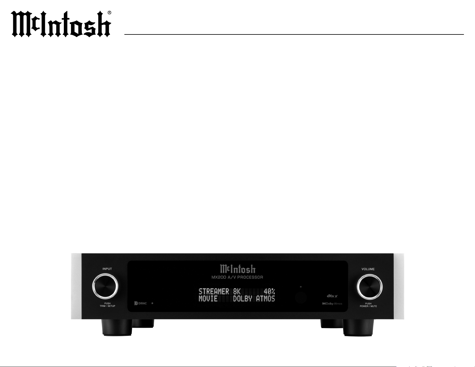
McIntosh Laboratory, Inc. 2 Chambers Street Binghamton, New York 13903-2699 Phone: 607-723-3512 www.mcintoshlabs.com
A/V PROCESSOR
OWNER’S MANUAL
Page 2

Thank You from all of us at McIntosh
Safety First
Performance Features
You have invested in a precision instrument that
will provide you with many years of enjoyment.
Please take a few moments to familiarize yourself
with the features and instructions to get the
If you need further technical assistance, please
contact your dealer who may be more familiar with
your particular setup including other brands. You
or in the unlikely event of needing service.
McIntosh Laboratory, Inc.
Technical Assistance
Customer Service
Email [email protected]
www.mcintoshlabs.com
Please read the safety instructions included in a
separate document called Important Additional
Operation Information Guide.
What is in the box
materials:
•
• One accessory package including:
• Microphone with attached cable
• Microphone stand
•
• One hardware package including:
• Two Side Rack Mounting brackets
•
•
• One manual package including this manual
•
•
• Special Power Supply
Separate high speed switching power supply plus
low noise analog supply applied for optimum low
noise performace.
• Front Panel Illumination
The even illumination of the front panel is
accomplished by the combination of custom
Light Emitting Diodes (LEDs).
• Glass Front Panel Display
The famous McIntosh illuminated glass front
setup and status notices
•
Remote Control with External Sensor Input
source components. Enjoy your McIntosh system
from other rooms in your home by connecting
.
Please Take A Moment
For future reference, you can write down your
serial number and purchase information here.
We can identify your purchase from this informa
tion if the occasion should arise:
Serial Number: __________________________
Purchase Date: ___________________________
Dealer Name: ___________________________
2
Introduction
Now you can take advantage of traditional McIntosh
Audio/Video Processor marries a long tradition of
“the sound of the music itself.”
Page 3
Custom Installation
MX200
Table of Contents
Front Panel
Side Panel
components, use a ventilation fan to provide cool operating temperature.
•
•
•
•
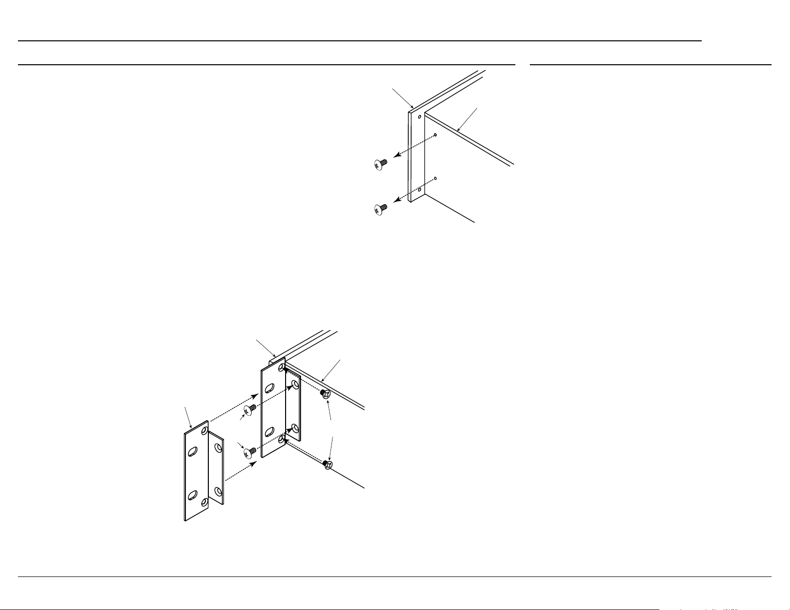
Rack Mounting
Follow these instructions for each side:
1.
mounting brackets are removed.
2.
previously removed screws. Use the smaller supplied screws to secure the bracket to the front panel.
Front Panel
Side Panel
Side Rack
Mounting
Bracket
Larger
Supplied
Screws
Smaller Supplied
Screws
Introduction . .. .. .. .. .. .. .. .. .. .. .. .. .. .. 2
Performance Features
Custom Installation
Rack Mounting
Connector and Cable Information
Balanced Audio Outputs
Trademark and License Information
Dimensions
.. .. .. .. .. .. .. .. .. .. .. .. .. .. .. 6
Navigating the Remote Control
Front Panel
Rear Panel
Trim Menu
Input Mode
.. .. .. .. .. .. .. .. .. .. .. .. .. .. .. 8
.. .. .. .. .. .. .. .. .. .. .. .. .. .. .. 9
.. .. .. .. .. .. .. .. .. .. .. .. .. .. ..10
.. .. .. .. .. .. .. .. .. .. .. .. .. ..
Assigning Input Modes
Voici ng EQ
Setup Menu
. .. .. .. .. .. .. .. .. .. .. .. .. .. ..11
.. .. .. .. .. .. .. .. .. .. .. .. .. .. ..12
Inputs Setup Menu
General Setup Menu
Audio Setup Menu
Video Setup Menu
Network Setup Menu
Speakers Setup Menu
Speaker Placement
Dirac Live
®
Setup. .. .. .. .. .. .. .. .. .. .. .. ..22
Connection Diagram
Setting Up Surround Sound
Specifications
.. .. .. .. .. .. .. .. .. .. .. .. .. . 26
Packing Instructions
Part List
.. .. .. .. .. .. .. .. .. .. .. .. .. .. .. ..27
.. .. .. .. .. .. .. .. .. .. .. 2
. .. .. .. .. .. .. .. .. .. .. .. 3
.. .. .. .. .. .. .. .. .. .. .. .. .. 3
. .. .. .. .. .. 4
.. .. .. .. .. .. .. .. ..
. .. .. .. .. 5
.. .. .. .. .. .. .. 7
.. .. .. .. .. .. .. .. ..
. .. .. .. .. .. ..
.. .. .. .. .. .. .. .. .. ..
.. .. .. .. .. .. .. .. .. .. .. ..13
.. .. .. .. .. .. .. .. .. 14-15
.. .. .. .. .. .. .. .. .. .. 16 -17
.. .. .. .. .. .. .. .. .. .. .. ..18
.. .. .. .. .. .. .. .. .. .. ..19
.. .. .. .. .. .. .. .. .. .. . 20
.. .. .. .. .. .. .. .. .. .. .. ..21
. .. .. .. .. .. .. .. .. .. .. . 22
.. .. .. .. .. .. .. .. .. .. . 23
.. .. .. .. .. .. 24 -25
.. .. .. .. .. .. .. .. .. .. ..27
3
Page 4
Connector and Cable Information
Ground
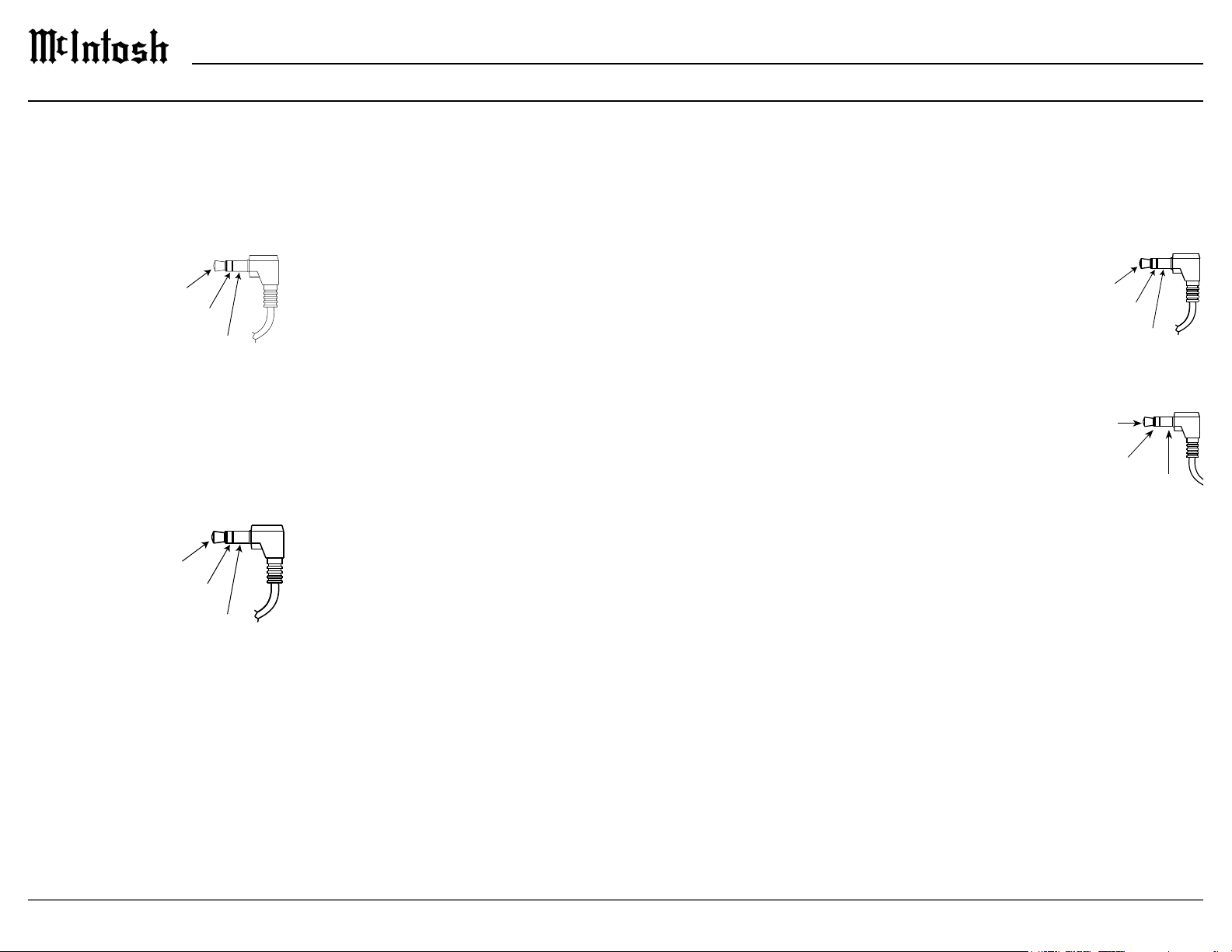
Power Control Connectors
is used for connection to the trigger outputs on the
Power
l
Lighting
l
Data Out Connector
share with McIntosh components connected to the
DATA OU T port on the rear panel. This will allow
the operation of primary functions of a source to be
as allow units that are out of range of an IR signal to
receive commands.
Data
Signal
N/C
Data
NET Port (Ethernet / 10baseT LAN)
a network router. The network connector is located
will automatically receive an IP address from the
router. This setting can be changed.
HDMI
video. To take advantage of this new capability, the
backward compatible, older cables may have issues
with the higher bandwidth.
television.
functions to ensure audio and video are perfectly
matched. This allows for more intelligent operation
between components as well as less cable clutter.
menu.
Atmos and DTS:X.
USB
The USB port is not for
general USB use or charging devices.
Microphone
microphone is used in the Dirac Live
tuning the system to your room. For instructions see
“Dirac Live® Setup” on page 22.
®
calibration for
IR IN Port Connector
the remote control can be used in another location
IR sensors such as a Xantech
Note: The IR receiver must provide its own
power supply.
IR Data
Control
N/C
Ground
RS232
controllers.
Typical RS232 settings are:
•
one stop bit
Data being transmitted
Data being received
•
bits per second
AC Power
This connection is essential. Plug the supplied
Page 5
Balanced Audio Outputs
MX200
Trademark and License Information
There are 11 male balanced XLR connections on
XLR cables to the corresponding powered speakers
• FR (Front Right)
• FL (Front Left)
•
• SR (Surround Right)
• SL (Surround Left)
• SBR (Surround Back Right)
• SBL (Surround Back Left)
• HR1 (Height Right 1)
• HL1 (Height Left 1)
• HR2 (Height Right 2)
• HL2 (Height Left 2)
HR1 and HL1 should be forward of HR2 and HL2.
Top Front, Top Middle and Top Rear locations.
Setting up speakers for a surround setup takes
planning, measuring and installation. Depending on
wish to employ the services of your McIntosh dealer
due to gravity and the location above your head. For
more information see “
Setting Up Surround Sound”
Unbalanced Audio Outputs
• SW1 (Subwoofer 1)
• SW2 (Subwoofer 2)
protected technology that is protected by U.S. patents
uses the following technologies:
Trademark Logo License Information
Dolby, Dolby Atmos, and
registered trademarks
of Dolby Laboratories
Manufactured under license
from Dolby Laboratories.
Laboratories. All rights
reserved.
The terms HDMI, HDMI
Interface, and the HDMI
Logo are trademarks or
registered trademarks
of HDMI Licensing
Administrator, Inc.
Manufactured under license
from Dirac Live. Dirac Live,
®
Dirac
and Dirac Live® are
trademarks owned by Dirac
Research AB.
For DTS patents, see
http://patents.dts.com.
Manufactured under license
from DTS Licensing
Limited. DTS, DTS:X,
and the DTS:X logo are
registered trademarks or
trademarks of DTS, Inc. in
the United States and other
All rights reserved.
Page 6
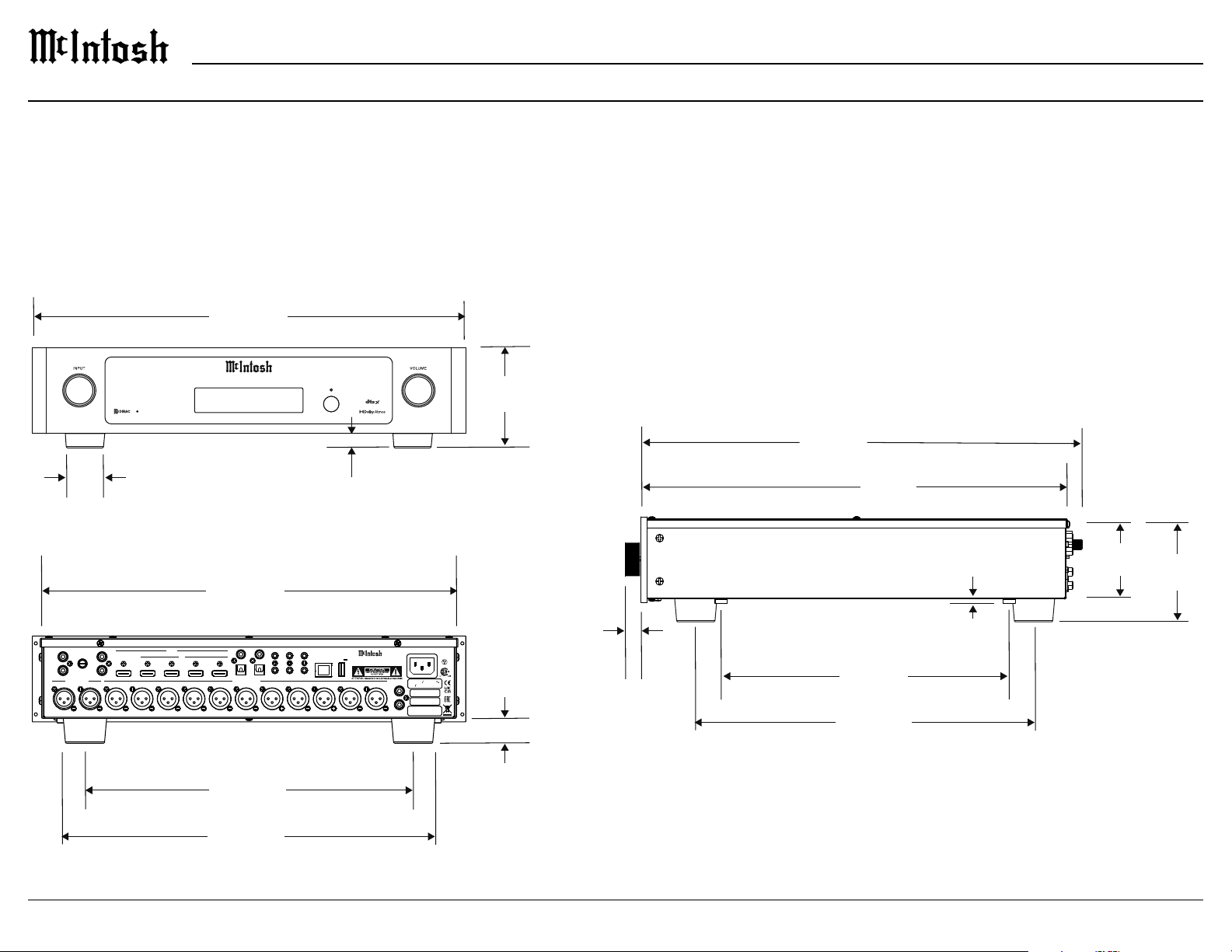
Dimensions
A Note on Placement:
It is important to keep your McIntosh unit out of direct sunlight and only use appropriate gentle cleaners because the organic anodize can become discolored
over time.
While most products will maintain their classic dark features for their lifetime, some situations can accelerate discoloration. The most pervasive culprit is UV
17 ⁄”
44.5 cm
PR O CE S SO RA/VMX2 00
PUSH
TRIM / SETUP
1 ⁄”
39.7 mm
PR O CE S SO RA/VMX2 00
BLURAY 4K 55%
BLURAY 4K 55%
Movie Dolby Atmos
Movie Dolby Atmos
⁄”
23.8 mm
PUSH
POWER / MUTE
4 ⁄”
11.1 cm
17 ⁄”
44.9 cm
17 ⁄”
44.1 cm
3 ⁄”
4 ⁄”
10.9 cm
MM
L
R
BALANCED IN
AUX 2R AUX 2L
16 ⁄”
42.9 cm
INNER DIMENSION
AUX 1
GND
L
OUT/eARC
R
RF LF C LS RB LB RH1RS LH1 RH2 LH2
1 2
HDMI
IN
4
3
1
1
DIGITAL INPUTS
BALANCED OUT
2
RS232
TRIG 1 IR IN
COAX
2
OPT
SETUP MIC
TRIG 2
8.3 cm
⁄”
SERVICE
USB
5V/1A
NET
DATA OUT
MX200
A/V P ROCE SSOR
McINTOSH LABORATORY, INC., BINGHAMTON, NY
HANDCRAFTED IN US A WIT H US AND IMPOR TED PAR TS
SW1
SW2
UNBAL OUT
100- 120V 220-240V
50 60Hz 30 WATTS
MAC ID
MAC ID
SERIAL
NUMBER
16.7 mm
1 ⁄”
26.2 mm
11 ⁄”
29.7 cm
13 ⁄”
34.8 cm
⁄”
4.8 mm
13 ⁄”
33.7 cm
15”
38.1 cm
6
Page 7
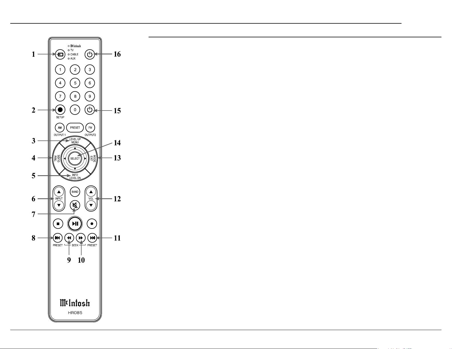
Navigating the Remote Control
MX200
1. Switch Device:
operation. Selected device is indicated by the LED
light.
2. Setup Button: Used to enter setup mode.
3. Level Up/Menu: Accesses menu on compatible
devices.
4. Trim /Guide: Enters trim functions menu. Opens
guide on compatible devices.
5. Info/Level Down: Accesses info on compatible
devices.
6. Input:
7. Mute: Mutes audio playback.
8. Previous/Previous Preset: Return to your previ
ous media selection.
9. Fast Reverse/Seek Down: Navigate backwards
through the current active media using this button.
10. Fast Forward/Seek Up: Navigate forward
through the current active media using this button.
11. Next/Next Preset:
12. Volume: Used to adjust the volume.
13. Mode/Exit:
menu. It will also display information or certain
options.
14. Select: Selects the highlighted option.
15. Power O:
the LED.
16. Power On: Turns on the selected device shown by
the LED.
Note: The HR085 Remote Control has buttons used to control multiple
devices. Buttons whose function are not described are for use
with other McIntosh products.
For more information, refer to the HR085 Owner's Manual on
the McIntosh website at www.mcintoshlabs.com.
Remote Control Batteries
included). To insert or remove batteries, open the
battery compartment by removing the cover located
on the back of the remote control. To open, pull the
clasp located just above the opening downward.
Additional Discrete Commands
systems are available:
• OPT1
• OPT2
•
•
• HDMI1
• HDMI2
• HDMI3
•
• HDMITV
• PHONO
• AUX 1
• AUX 2
•
These additional commands can be accessed
Assistance or your dealer for more information.
Page 8
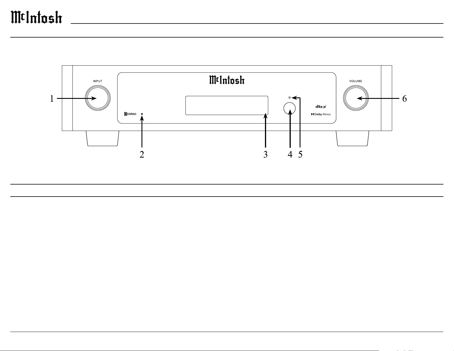
Front Panel
Front Panel
PUSH
TRIM / SE TUP
P R O C E S S O RA/ VMX 2 0 0
P R O C E S S O RA/ VMX 2 0 0
BLURAY 4K 55%
BLURAY 4K 55%
Movie Dolby Atmos
Movie Dolby Atmos
PUSH
POWER / M UTE
1. INPUT K NOB is used for the following:
• Input Selection: Turn clockwise or counter
clockwise to scroll through inputs.
• Trim Menu: Push and release to enter Trim
Mode and rotate to navigate through options.
• Setup Menu: Push, hold for two seconds, and
release to enter setup mode.
2. Dirac Live LED shows whether Dirac Live EQ
is engaged, LED will be lit, or disengaged, LED
will not be lit.
3. VFD
character screen shows various messages for
setup/trim and playback conditions.
4. IR Sensor
remote control.
5. Standby LED
current power status.
6. VOLUME K NOB is used for the following:
• Power ON: Quick press to power on the
• Adjust Volume: Rotate to adjust the volume.
• Mute:
• Setup/Tr i m: Rotate to adjust Trim options once
the menus are accessed using the INPUT knob.
• Power OFF: Push and hold for 2 seconds to
appear on the display.
Page 9
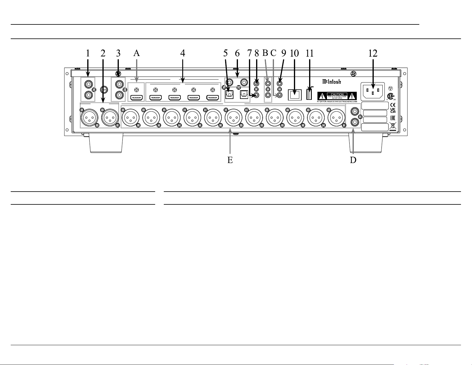
MX200
Rear Panel Connections
MM
L
R
BALANCED IN
AUX 2R AUX 2L
AUX 1
GND
L
R
OUT/eARC
1 2
RF LF C LS RB LB RH1RS LH1 RH2 LH2
HDMI
IN
3
1
4
1
DIGITAL INPUTS
BALANCED OUT
Rear Panel Inputs Rear Panel Outputs
1.
2.
3.
Four HDMI IN
Two Toslink optical inputs
6.
9.
11. One USB upgrade service port
12.
A.
Note: Acts as an audio input when ARC is active.
B.
D. Two unbalanced subwoofer outputs are available to
connect to powered subwoofers.
• SW1 (Subwoofer 1)
• SW2 (Subwoofer 2)
COAX
OPT
2
RS232
TRIG 1 IR IN
2
SETUP MIC
TRIG 2
DATA OUT
SERVICE
USB
5V/1A
NET
McINTOSH LABORATORY, INC., BINGHAMTON, NY
HANDCR AFTED IN U SA WI TH US AND IMPOR TED PA RTS
MX200
A/V PR OCES SOR
UNBAL OUT
SW1
SW2
MAC ID
MAC ID
SERIAL
NUMBER
E.
• FR (Front Right)
• FL (Front Left)
•
• SR (Surround Right)
• SL (Surround Left)
• SBR (Surround Back Right)
• SBL (Surround Back Left)
• HR1
• HL1
• HR2
• HL2
Note: HR1 and HL1 should be forward of HR2 and HL2. The
MX200 support of Height speakers is limited to Top Front,
Top Middle and Top Rear locations.
9
Page 10
Trim Menu
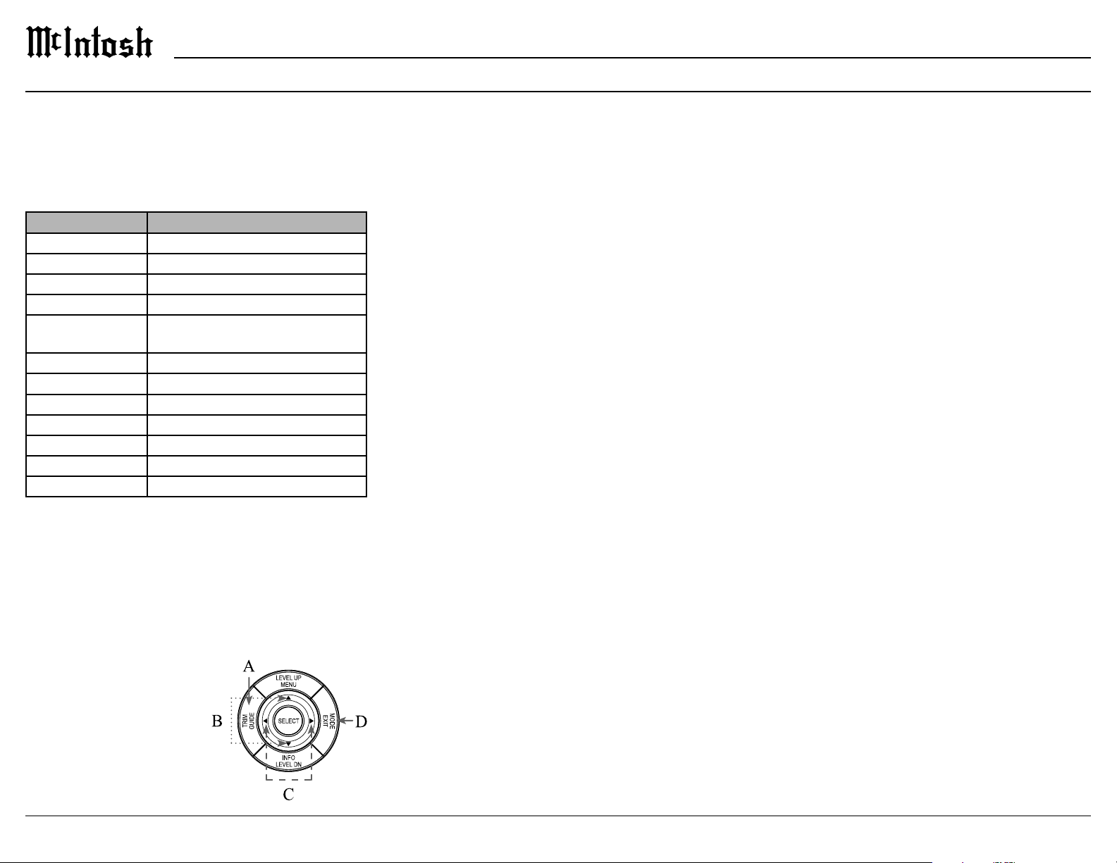
The trim menu allows you to make and store
adjustments to various settings for all inputs. The
trim menu can be entered using the INPUT knob or
the remote control.
The following table lists the trim options and the
range of values that can be adjusted:
Setting Values
Bass
Treble
Dirac Live
Voicing EQ Select to apply to current input
Audio Delay
(Lip Sync)
Trim Surrounds
Trim Heights
Trim Subwoofer
Meter Lights
Display Brightness
Input Mode
Trim Menu Using the Remote Control
A. Enter the trim menu by pressing the TRIM button.
B. You can scroll through the trim options by press
ing the up or down arrows on the silver ring.
Use the left and right arrows on the silver ring to
change values for the selected trim option.
D.
ten seconds for the menu
to close automatically.
Trim Menu Using Knobs
To enter the trim menu, press and release the
INPUT knob. (Holding the knob for two seconds
enters the setup menu instead of the trim menu.)
Scroll through the options by turning the INPUT
knob.
the VOLUME knob. Turn the INPUT knob to select
another option to edit or press the INPUT knob and
Saving Trim Settings
Most trim settings are saved per input. For these
input. The following trim inputs are saved by
individual input:
• Bass
• Treble
• Audio Delay
•
• Trim Surrounds
• Trim Subwoofer
• Mode
• Voici ng EQ
change to these settings for any input will make the
same change for all inputs
• Dirac Live EQ
• Meter Lights
• Display Brightness
Input Mode
The following input modes are available:
• AUTO
•
• MOVIE
•
•
for each option is AUTO. Other options are Dolby
Stereo and Through. For more information about
these options see “Setup: Audio > surround mode”
on page 16.
mode is to use the MODE button on the outer ring
of the remote control. Pressing the MODE button
will cycle through the surround modes. Stop on your
and your choice will be saved.
Assigning Input Modes
A. Enter the trim menu by pressing the INPUT knob
or the TRIM button on the remote control.
B. Rotate the INPUT knob or press the down arrow
on the remote control until MODE is displayed on
the VFD.
button on the remote control.
D. Rotate the INPUT knob or the up and down
arrows on the remote control until the desired
input is displayed.
E. Rotate the VOLUME knob or press the left and
right arrows to scroll through the surround modes.
F. Press and hold the INPUT knob for two seconds or
press the EXIT button to leave the trim menu (or
wait until it times out).
Page 11
MX200
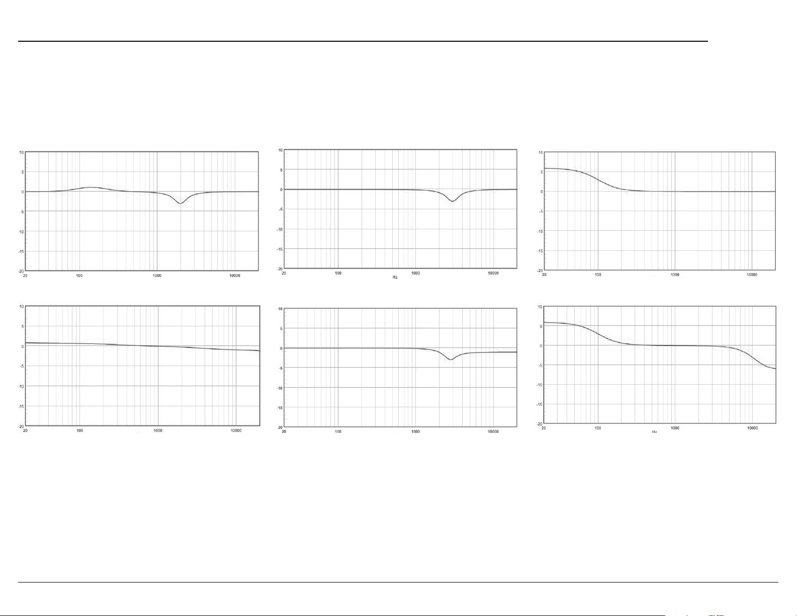
Voicing EQ
Voicing EQ select sets an easy tonal adjustment to enhance playback enjoyment. The selection is set to the current input, and remains active with that input only until
Relaxed
Tilt
Music
Music II
Action
Action + Movie
11
Page 12
Setup Menu
Changing Settings
There are two ways to change the settings of the
1. Use the front panel and the Vacuum Fluorescent
Display (VFD) and the INPUT and VOLUME
knobs or the remote control
2. Using a browser on a connected computer
network, then using the front panel method can
accomplish almost all the same things using some
additional patience.
In this manual, submenus are denoted in the style:
SETUP: VIDEO > HDMI
The title above indicates from the setup menu choose
the video submenu and then HDMI.
Navigating Setup with the Front Panel
To enter setup mode using the front panel press
and hold the INPUT knob for two seconds and then
release. A shorter push of the INPUT knob will bring
up trim settings. See “Setting Up Surround Sound”
Select options using a brief press of the INPUT
knob. A long press of the INPUT knob will close the
setup menu.
To return to a previous menu, scroll down to last
top most menu, the last menu choice will be MENU
user input.
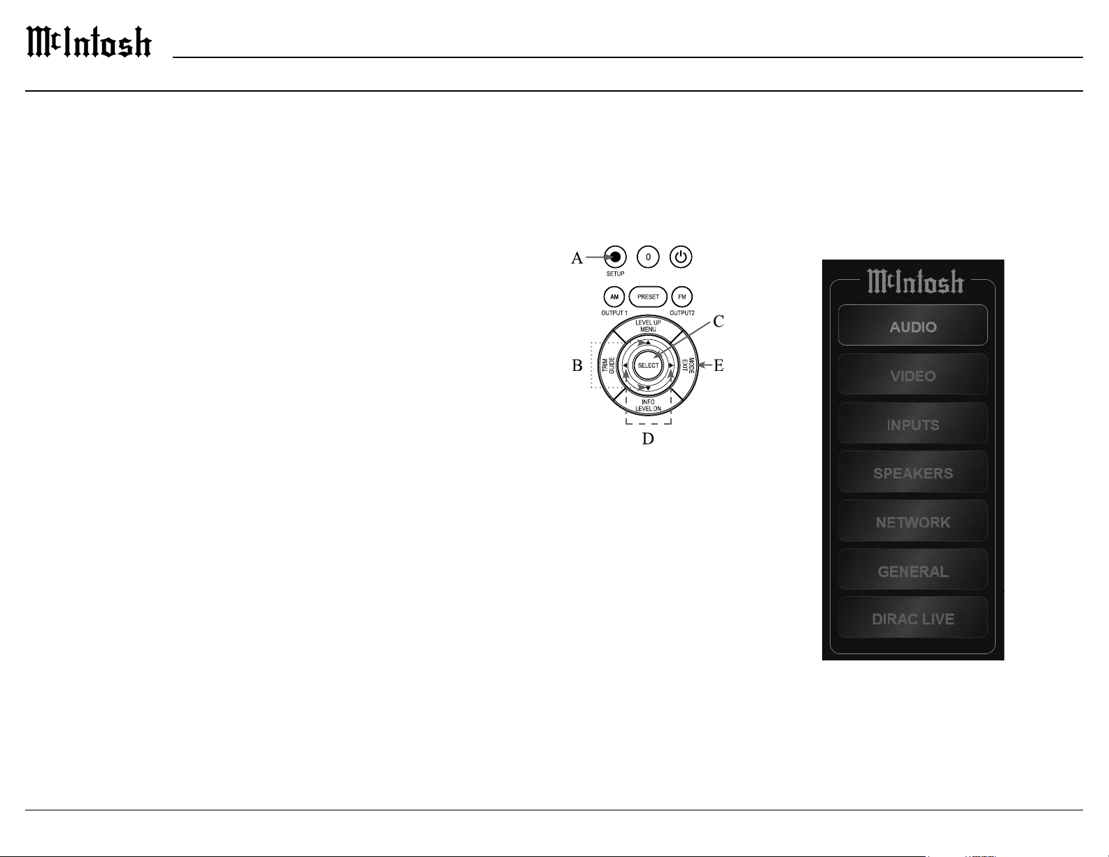
Navigating Setup with the Remote Control
A. Enter the setup menu by pressing the SETUP
button with the blue circle.
B. Use the up and down arrows on the silver ring to
navigate through the options.
change.
D. Use the left and right
arrows on the silver ring
to change values for the
selected setup option.
The new value will be
saved automatically.
E. To stop editing a setting
or to close the setup
menu, press the Mode/
the last option which is
Setup Menu Options
• Serial Number
• Firmware Version
• Inputs
• Network
•
• Audio
• Video
• Speakers
•
Setup from a Browser
Setup is easier from a web browser. Open a browser
window on a computer connected to the same
“Setup: Network > Network Information” on page
19).
The setup menu on your browser should look like
this:
12
Page 13

Inputs Setup Menu
MX200
Inputs Setup Menu from Browser
SETUP: INPUTS > HIDE SOURCES
The show/hide sources submenu allows you to
hide unused inputs. Hidden inputs do not appear as
input choices when scrolling through inputs. If you
hid inputs and want to show them again, they can be
restored by selecting “Show” on each or by choosing
“Show all” from your browser to make all inputs
visible.
SETUP: INPUTS > INPUT LEVEL
The input adjust section of the inputs menu allows
you to set a trim level for a source.
The Trim for each input can be individually set
default. If using the browser you can type in your
Setting Input Options
Hide Sources
Show/ Hide*
Input Level
Input Adjust*
Rename* HDMI 1
Note: Some options and settings are only available on the browser
version of the setup menu these are indicated with an *.
HDMI 1
HDMI 2
HDMI 3
HDMI TV
OPT 1
OPT 2
AUX 1
AUX 2
PHONO
HDMI 1
HDMI 2
HDMI 3
HDMI TV
OPT 1
OPT 2
AUX 1
AUX 2
PHONO
HDMI 2
HDMI 3
HDMI TV
OPT 1
OPT 2
AUX 1
AUX 2
PHONO
Show, Hide, or Show All*
TV AU DIO
DVD
Media Player
Default
Accessing the inputs setup menu from the browser
allows you to customize the name of an input as it
will appear on the display. Unused inputs can also be
hidden so as not to appear as choices. They can also
be easily restored when needed.
Renaming Inputs
To change the name of an input, choose one of
Note: Custom names have an 11 character limit and will not save
if you type more than 11 characters.
From the Rename submenu, you can choose from a
list of names for the input or chose “default” to keep
a custom name.
To use a custom name:
•
•
and type in the new name up to 11 characters
• Push the Enter key on your keyboard to save
13
Page 14
General Setup Menu
The general menu contains the following options:
Setting Options
Fi rmwa r e Ve rsion
Firmware Update Yes, N o
Factory Reset Yes , N o
Save and Load Save, Load
Trigger 1 All, None, Independent
Trigger 2 All, None, Independent
SETUP: GENERAL > FIRMWARE
Firmware is software that controls hardware at a
may be issued to address particular issues. If you
arise, your McIntosh dealer has access to the latest
directory of a properly formatted USB drive (FAT
or Fat32). The USB drive should be inserted into
the Update Now button will begin the process. It
is highly recommended that your McIntosh dealer
perform the update process since failure to properly
unusable state.
SETUP: GENERAL > FACTORY RESET
be saved and restored in the “Save and Load” section
of the general setup menu.
SETUP: GENERAL > SAVE AND LOAD > SAVE
or its environment.
Note: Configurations created using the browser interface must
be restored using this interface and CANNOT be restored
using the MX200’s front panel interface or MX200’s USB
port.
USB port, you must use the front panel interface.
To use the front panel interface to save the
•
•
Save
•
•
settings
SETUP: GENERAL > SAVE AND LOAD > LOAD
have custom named. Select open. The interface will
cycle and the new settings will be loaded.
If you are using the front panel to load a
•
port.
•
Load. Progress will be displayed for loading the
•
SETUP: GENERAL > TRIGGER
Trigger1 and Trigger2 can each be set to power on/
Each Trigger can be set to:
• Independent allows each individual input to be
is selected, connected components will receive a
power control signal to power on until the selected
• All On sets the power control setting of all inputs
to On. With this selection, any input will generate
a power control signal to be sent for that Trigger.
to On. You can switch to Independent to set any
Page 15

General Setup Menu (continued)
•
switch to Independent to set any individual input
to On.
When Independent is selected, you can select On or
• HDMI 1
• HDMI 2
• HDMI 3
•
• HDMI TV
• Optical 1
SETUP: GENERAL > FIRMWARE
• Optical 2
•
•
• AUX 1
• AUX 2
• PHONO
MX200
SETUP: GENERAL > RCLOCK
prevent the front IR sensor from receiving IR
commands from a remote control. The default for
lock to OFF (the default).
SETUP: GENERAL > AUTO OFF
there has been an absence of an audio input signal on
both channels.
When there is a power control connection between
Page 16
Audio Setup Menu
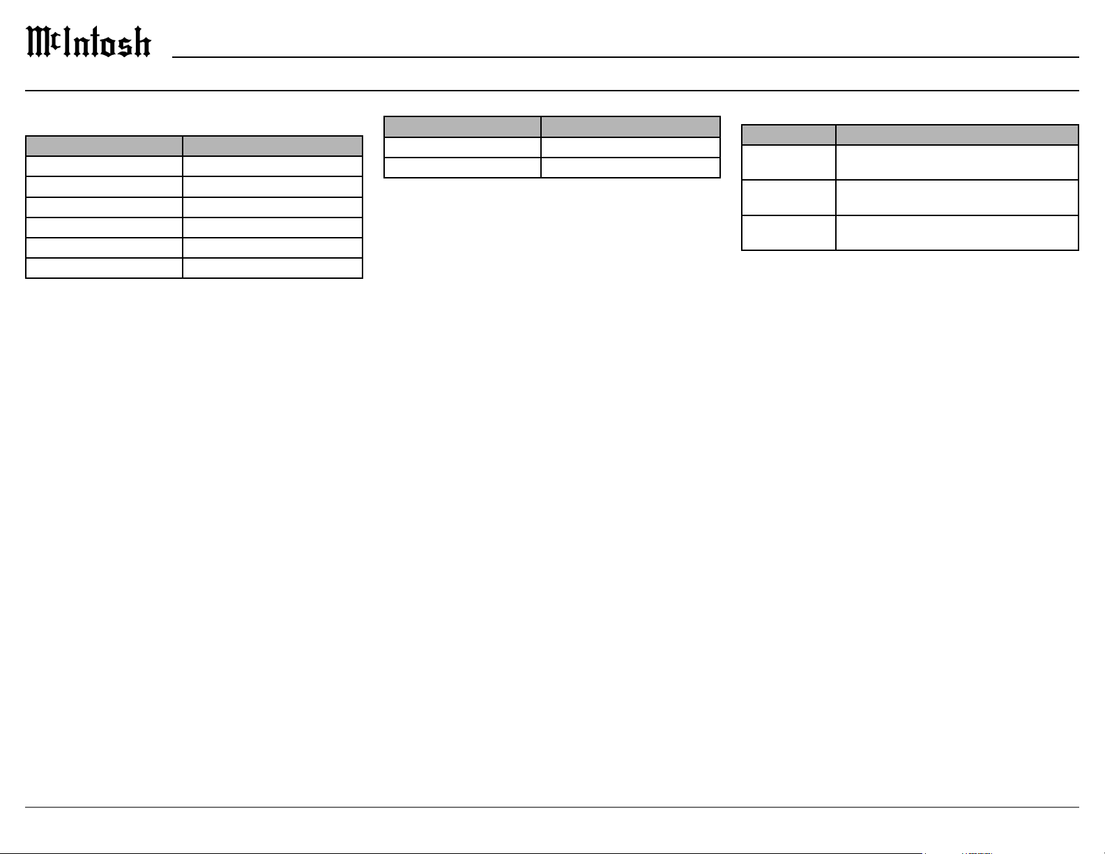
The audio setup menu contains the following
options:
Setting Options
Sub Level
Bass Sync
Audio Delay (Lip Sync)
Vol u me Scale, Limit
Surround Mode
ON, AUTO, OFF
Note: Some options and settings are only available on the browser
version of the setup menu these are indicated with an *.
SETUP: AUDIO > SUB LEVEL
Subwoofer level adjust allows for adjusting your
SETUP: AUDIO > BASS SYNC
(LFE) may be out of sync and delayed. This function
allows you to correct the delay with an adjustment of
SETUP: AUDIO > AUDIO DELAY
Audio delay (Lip Sync) compensates for incorrect
timing between video and audio. When auto lip
automatically corrected with compatible TVs. The
adjust option allows you to manually adjust the delay
Volume Submenu Options
Setting Options
Scale Linear, dB Level
Limit
SETUP: AUDIO > VOLUME > SCALE
There are two choices for how to display the
volume. The default is a volume scale linear which
second option is volume scale dB level. This will
Note: The displayed dB scale increments are not uniform as they
have been designed to give a meaning ful level adjustment
depending on the actual level being listened to.
using the slider. Slide towards the right to increase
and to the left to decrease the volume level. The
current volume percentage for the linear scale or dB
SETUP: AUDIO > VOLUME > LIMIT
threshold for how high the volume level can be set.
of these three volume limits:
•
•
•
level can not be set above the selected volume limit.
SETUP: AUDIO > SURROUND MODE
Setting Options
Music Through, Auto, Dolby Surround, Neural: X,
Multich Stereo, Stereo
Movie Through, Auto, Dolby Surround, Neural: X,
Multich Stereo, Stereo
Through, Auto, Dolby Surround, Neural: X,
Multich Stereo, Stereo
In the surround mode setup, you can assign a
surround mode to each of three sound categories:
• Music
• Movie
•
These three sound categories can be assigned to an
input using the trim menu, for more information refer
easier for someone unfamiliar with DTS or Dolby to
select the proper surround mode by selecting Music,
following choices in setup:
• Through
• AUTO (default)
• Dolby Surround
• DTS Neural:X
•
• Stereo
The surround mode represented by the Trim
in setup. If no assignment has been made, the default
for each is Auto.
16
Page 17

Audio Setup Menu (continued) Audio Setup Menu from Browser
MX200
speakers no matter the input audio stream type. It
ured speakers if the incoming audio stream is Dolby
encoded. It will use DTS Neural:X to send audio
no matter the input stream type.
no matter the input stream type.
to send audio to all left and right speakers (plus sub
surround mode is similar to party mode in similar
products. Use this setting to deliver audio to all
channels.
matter the input stream type.
Dynamic Range Compress
and Auto that apply to the HDMI inputs. Dynamic
of video sound while retaining the ability to hear
voices and reduced level sounds.
• OFF retains full dynamic range of the original
signal content.
• AUTO applies a medium level of compression that
may be more enjoyable under overall listening
conditions.
•
listening conditions.
Page 18
Video Setup Menu
Video Setup Menu from Browser
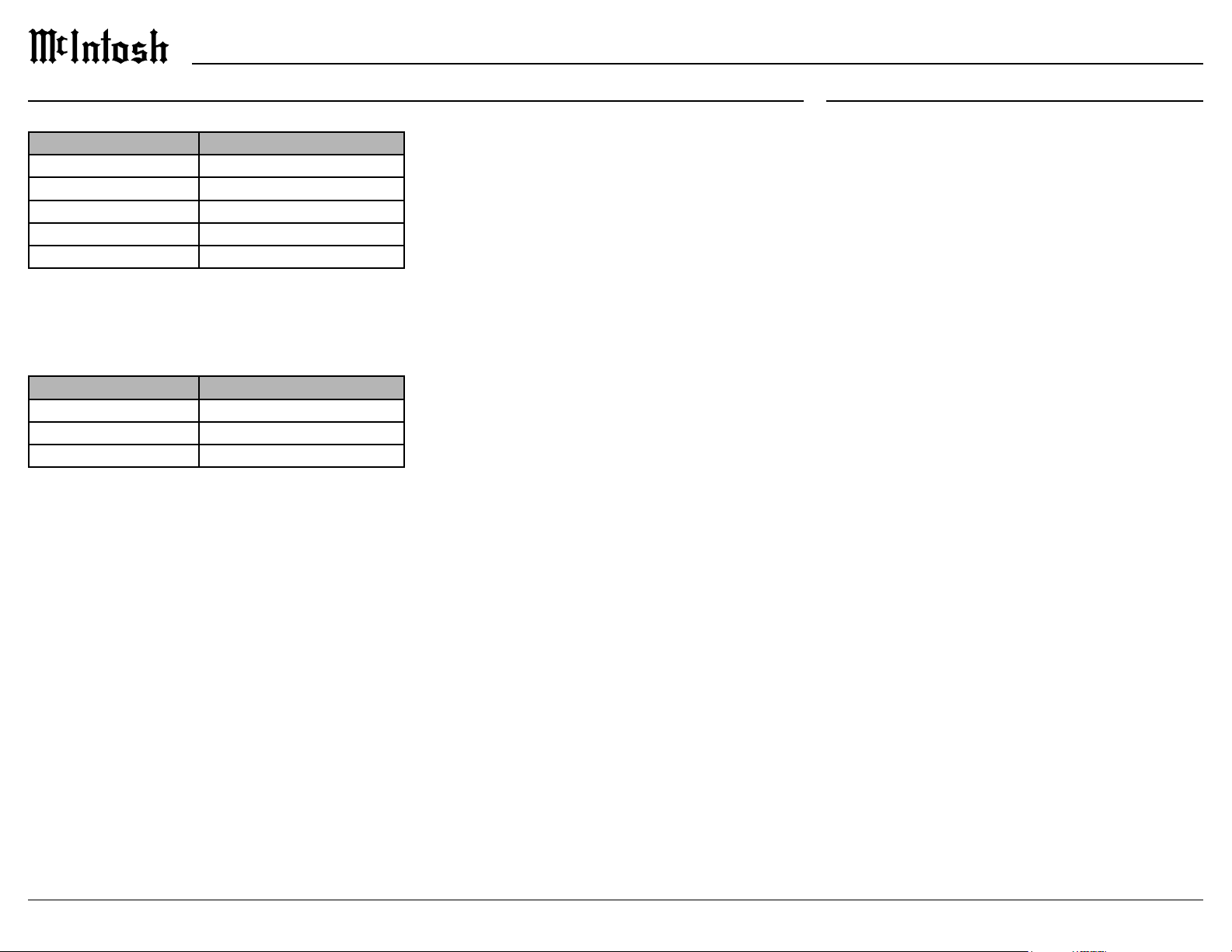
The video setup menu has the following options:
Setting Input
HDMI Setup Submenu described below
OFF, BOTTOM, TOP
TV Audio Switching* ON, OFF
ALL, VIDEO, OFF
Power Saving* ON, OFF
Note: Some options and settings are only available on the browser
version of the setup menu these are indicated with an *.
SETUP: VIDEO > HDMI SETUP
The Video setup menu has one main submenu for
HDMI settings, the options for it are shown below.
Setting Input
PASST H RU
ON, OFF
ON, OFF
SETUP: VIDEO > HDMI SETUP > PASS THRU
Pass through (written as HDMI PASSTHRU on the
front display) allows an HDMI input to be assigned
so that when a signal is received by that HDMI input,
received for video and audio playback by a connected
TV or monitor.
Note: CEC should be disabled if you plan to use the pass through
feature to avoid your TV turning on your MX200 and other
unexpected results.
SETUP: VIDEO > ON SCREEN DISP
On screen display, when On, will display the
volume on an attached TV when the volume is
Bottom and Top refer to the position on the TV
where the volume will be displayed. Both Bottom
and Top enable (on) the on screen display feature.
SETUP: VIDEO > HDMI SETUP > ARC
enabled, will work with the TV Audio input and a
functions to ensure audio and video are perfectly
matched. This allows for more intelligent operation
between components as well as less cable clutter.
SETUP: VIDEO > HDMI SETUP > CEC
to the HDMI standard which allows control signals
from one device to communicate with another device
via an HDMI cable connection. If you change HDMI
control settings, reset power to connected devices.
Notes: 1. To use ARC, CEC must also be set to On.
2. To use CEC and the additional commands of TV
audio switching, power off control and power
saving, CEC must be set to on, so your television and
MX200 can better communicate.
3. To power ON the MX200 via CEC, ensure Network
Control is set to ON.
certainly getting better, but not every component in
the world is speaking precisely the same language.
There may be circumstances where you may have
These features can be enabled or disabled at any time
and are only accessible through the browser interface
of the setup menu.
TV Audio Switching
TV audio switching, when set to ON, will switch to
TV audio when receiving a command from the TV.
cally switch to TV audio when receiving a command
from the TV.
Power O Control
Power Saving
Page 19
Network Setup Menu
MX200
SETUP: NETWORK
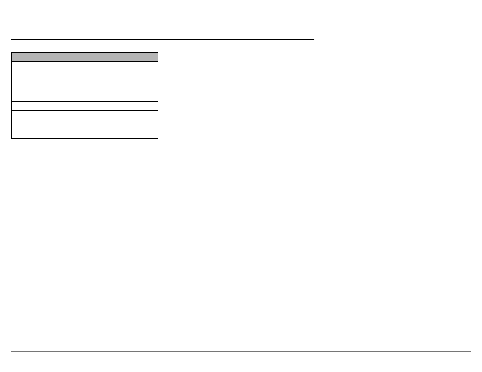
Setting Options
Network
Information
Network Identify
Friendly Name
Note: Some options and settings are only available on the browser
version of the setup menu these are indicated with an *.
SETUP: NETWORK > NETWORK INFORMATION
Host IP Address
Host Mac Address
Dirac IP Address
Room, Master Bedroom, Bedroom,
•
•
address.
•
address.
•
SETUP: NETWORK > NETWORK CONTROL
a control system such as one using RS232 commands
SETUP: NETWORK > FRIENDLY NAME
Friendly name provides a more individual way of
that recognize friendly names.
changed by selecting an alternative name from the
only be entered from the browser interface. Preset
names can be chosen using the front panel or your
remote control.
Network Settings
Network settings allows you manually entering
network information. You may do this if you want to
information will be assigned automatically from your
router.
• IP address
•
•
• DNS address (typically the IP address of your
router)
When you have completed making network settings
changes, select the “Apply All Settings” button to
save your changes.
19
Page 20
Speakers Setup Menu
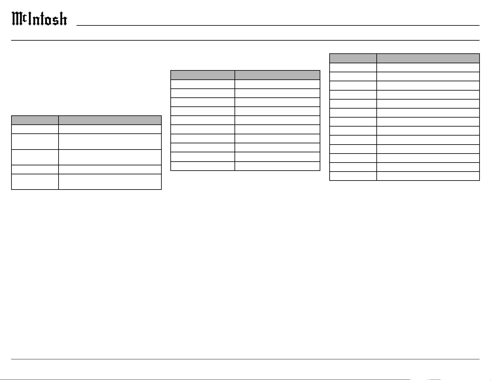
The speakers setup menu contains the following
submenus:
• Amp Assign
•
• Speaker Distances
• Speaker Level
•
SETUP: SPEAKERS > AMP ASSIGN
Setting Options
Manual Floor
Manual Top SP
Top Speaker
Top Layout
Manual Dolby
Dolby Layout
Note:
1. Some settings are only available on the browser version of
the setup menu these are indicated with an *.
2. Choosing some options will eliminate others.
In amp assign, you select how to use the preampli
scheme you will be using. This assignment is neces
sary before running Dirac Live.
SETUP: SPEAKERS > SPEAKER CONFIG
The available speaker categories are based on the
settings in Amp Assign (see above).
Speaker Options
Front Large / Small
Large / Small / None
Subwoofe r (SUB) 1 speaker / 2 speaker / None
Surround (SUR) Large / Small / None
Front Height (FR HT) Large / Small
Large / Small
Top Front* Large / Small
Top Re a r* Large / Small
Top Middle* Large / Small
Note: 1. Some settings are only available on the browser version of
the setup menu these are indicated with an *.
2. Choosing some options will eliminate other options.
Large / Small
Small.
SETUP: SPEAKERS > SPEAKER DISTANCES
Setting Options
Front Left
Front Right
Surround Right
Rear Right
Rear Left
Surround Left
Top Front Left*
Top Front Right*
Top Rear Left
Top Rear Right
Subwoofer 1
Subwoofer 2
Note:
Some settings are only available on the browser version of
the setup menu these are indicated with an *.
The input of distances of your speakers can be
entered manually. Distances will be provided
automatically when the Dirac Live setup program
is run, after which they can be edited. Having an
accurate accounting of your speaker speeds the Dirac
Live process by avoiding Dirac Live looking for
phantom speakers.
For each speaker, enter the distance from the main
listening position to the speaker in meters. To convert
information. The information entered here provides a
For Dolby enabled speakers, enter the distance to
the speaker. Do not calculate the angled path that the
this.
Page 21
MX200
Speakers Setup Menu (continued)
SETUP: SPEAKERS > SPEAKER LEVEL
Setting Options
Test To n e
Front Left
Front Right
Surround Right
Rear Right
Rear Left
Surround Left
Top Left Front*
Top Right Front*
Top Rear Left
Top Rear Right
Subwoofer 1
Subwoofer 2
Note: Some settings are only available on the browser version of
the setup menu these are indicated with an *.
The test tones and levels submenu provides the
ability to manually set relative levels for all speaker
This does not need to be set if using Dirac Live
calibration.
When test tone is set to On, a tone will play through
Dirac Live will automatically set levels and will
setting test tones will replace Dirac Live settings.
SETUP: SPEAKERS > CROSSOVER
Setting Options
Dependence Independent, All
Independent
Bass Type
Bass LP Filter
from the output to “small” speakers and is sent to the
subwoofer or front speakers. Most small speakers use a
chosen value. Independent will allow each available
SETUP: SPEAKERS > CROSSOVER > BASS TYPE
When the subwoofer mode is set to LFE (Low
of speakers set to small is sent to the subwoofer
of the main channel are sent to the subwoofer.
SETUP: SPEAKERS > CROSSOVER > BASS LP FILTER
chosen option will not be sent to the subwoofer. The
LPF setting does not apply to content sent from the
LFE channel to the subwoofers.
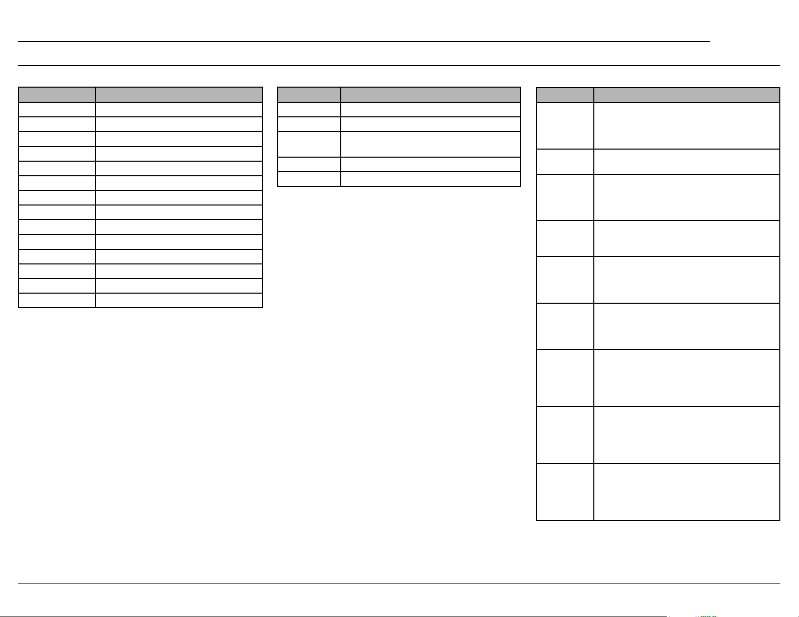
Speaker Placement
Speaker Position
Front The Front Left and Right speakers should
position. The distance between each speaker
and your TV should also be about the same.
The Middle speaker should be between the
Front speakers and above or below your TV.
Top Front Mount the Top Front Left and Right speakers
on the ceiling slightly in front of your main
listening position and align with the Left and
Right Front speakers.
Top Middle Mount the Top Middle Left and Right speakers
directly above the main listening position and
align with the Left and Right Front speakers.
Top Re a r Mount the Top Rear Left and Right speakers
on the ceiling slightly behind your main
listening position and align with the Left and
Right Front speakers.
Subwoofer Place the Subwoofer at a convenient location
near the Front speakers. If you have two
Subwoofers, place them asymmetrically across
the front of your room.
Front Dolby
speaker
Left/Right
Surround
Dolby
speaker
Back Dolby
speaker
More information about speaker placement can be
Place the Front Dolby Enabled speakers on
the Front speakers (left and right). For a Dolby
Atmos Enabled speaker integrated with a
Front speaker, place the Dolby Atmos Enabled
speaker instead of the Front speaker.
Place the Surround Dolby Enabled speaker
on the Surround speaker. For a Dolby Atmos
Enabled speaker integrated with a Surround
speaker, place the Dolby Atmos Enabled
speaker instead of the Surround speaker.
Place the Back Dolby Enabled speaker on the
surround back speaker. For a Dolby Atmos
Enabled speaker integrated with a Surround
Back speaker, place the Dolby Atmos Enabled
speaker instead of the Surround Back speaker.
21
Page 22

Dirac Live® Setup
Please review the Dirac Live User manual setup
and operation before beginning to calibrate your
system. Information regarding the user manual and
other tips may be found at
1.
https://www.dirac.com/live/downloads
2.
layout using either the front panel or the browser
which proper channels to enable to deliver audio
Note: After completing “Amp Assign”, press “Next”, and finally
press “Start.” This refreshes NET connection to DIRAC
within the MX200. Please wait at least 30 seconds to
connect to the MX200 within the Dirac Live app.
3.
lights, etc.).
Select Device (MX200)
Select recording device (microphone). An icon
with a microphone should appear with a graph.
6.
Select “Use from device.”
Volume Calibration
Set the Master output to a low setting to avoid
damage to ears or speakers.
9.
Use the Play Button to test channels individually
to hear if their level is suitable. Slowly raise the
master output level until sound can be heard.
• Repeat this step for each speaker.
11. Once each channel is complete, adjust the Master
output to a normal or slightly loud listening level.
Calibration notes:
• A common master volume range is -35dB to -25dB.
• A signal-to-noise ratio error indicates too low of audio to
measure. Master output may need to increase.
• A clipping error indicates too high of an audio level to
measure. Master output may need to decrease.
• If your subwoofer has gain control, this control may need to
be adjusted to assist with the volume calibration of that channel.
Select Arrangement
12.
measurements: Tightly Focused, Focused, and
Wide Imaging.
13. Please choose one that matches closest to your
own listening arrangement. A wider listening
positions with the microphone
Measure
Place the microphone closest to the listening
position shown in arrangement image.
Press “Measure selected position.”
16.
Note: While measuring a 7.2.4 system, the test tone will appear to
come from both subwoofers together. This is normal.
measured.
measurement.
19.
Note: Please take the time to SAVE your current project at this
point, as it will allow you to open this measurement and edit
your filter in the future without having to remeasure your
arrangement again.
Filter Design
Dirac Live will automatically generate a
performance and tune their response to meet the
suggested curve. These curves can be adjusted to
your preferences.
21. To manually adjust the generated curve, follow
the Dirac Live User Manual on Filter Design.
Filter Export
22.
23. Dirac will give the opportunity to name and
The Dirac Live process is now complete, and
Dirac may be enabled or disabled with available
Future Filter Edits:
Amp Assignment must be set to the same settings
as when the project was measured with to be able
22
Page 23
NET NET NET NET
TV
E
BL U - RAY PLAY ER
MIC
ROUTER
NET NET NET NET
MX200
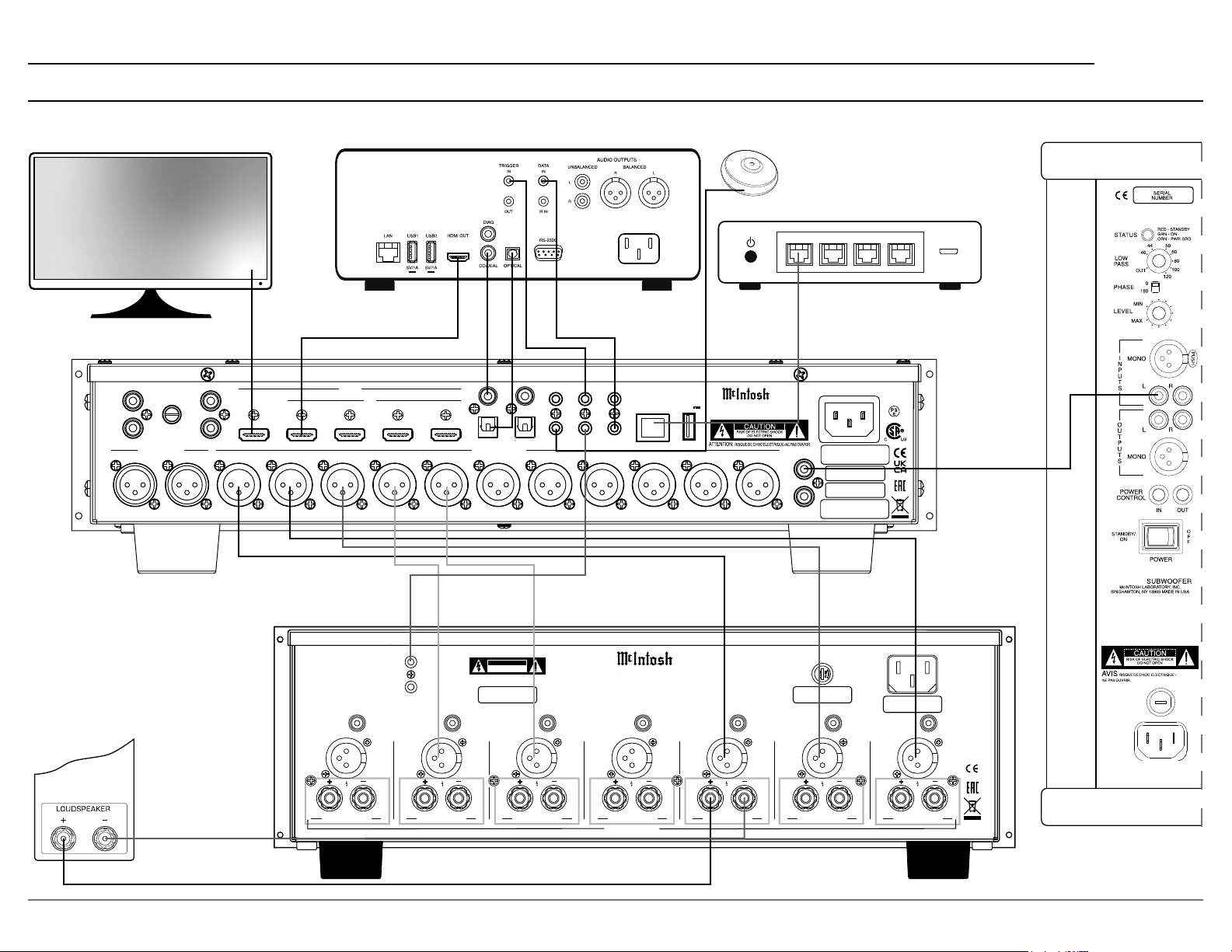
Connection Diagram
SUBWOOFER
(up to 2)
MM
L
R
AUX 2R AUX 2L
LOUDSPEAKERS
GND
BALANCED IN
AUX 1
L
OUT/eARC
R
RF LF C LS RB LB RH1RS LH1 RH2 LH2
1 2
HDMI
IN
3
IN
POWER
CONTROL
OUT
UNBAL
–
+
CHANNEL 7-RB CHANNEL 6-RS CHANNEL 5-LS CHANNEL 4-LB CHANNEL 3-RF CHANNEL 2-C CHANNEL 1-LF
UNBAL
BALBAL BAL
+
4
–
1
1
DIGITAL INPUTS
BALANCED OUT
ATTENTION: RISQUE DE CHOC ELECTRIQUE-NE PAS OUVRIR
COAX
OPT
CAUTION
RISK OF ELECTRIC SHOCK
DO NOT OPEN
SERIAL
NUMBER
2
UNBAL
+
2
SETUP MIC
RS232
TRIG 1 IR IN
TRIG 2
DATA OUT
MI347 SEVEN CHANNEL POWER AMPLIFIER
HANDCRAFTED IN USA WITH US AND IMPORTED PARTS
BAL BAL
–
McINTOSH LABORATORY, INC.,
BINGHAMTON, NY
UNBAL
+
CLASS 2 WIRING
NET
–
SERVICE
USB
5V/1A
McINTOSH LABORATORY, INC., BINGHAMTON, NY
HANDCR AFTED IN U SA WI TH US AND IMPOR TED PA RTS
UNBAL
+
MX200
A/V PR OCES SOR
–
UNBAL OUT
SW1
SW2
BAL
15AH 250V
UNBAL
+
MAC ID
MAC ID
SERIAL
NUMBER
E
FUS
PUSH
100V-240V
50/60Hz 10A
UNBAL
BAL
–
–
+
23
Page 24
Setting Up Surround Sound
GOOD
2-LS 6-RS
1-LB 7-R B
3-L 5-R
4-C
SW -1
SW-2
SW -1
SW-2
GOOD
ART
H1-L H1-R
H2-L H2-R
H1-L H1-R
H2-L H2-R
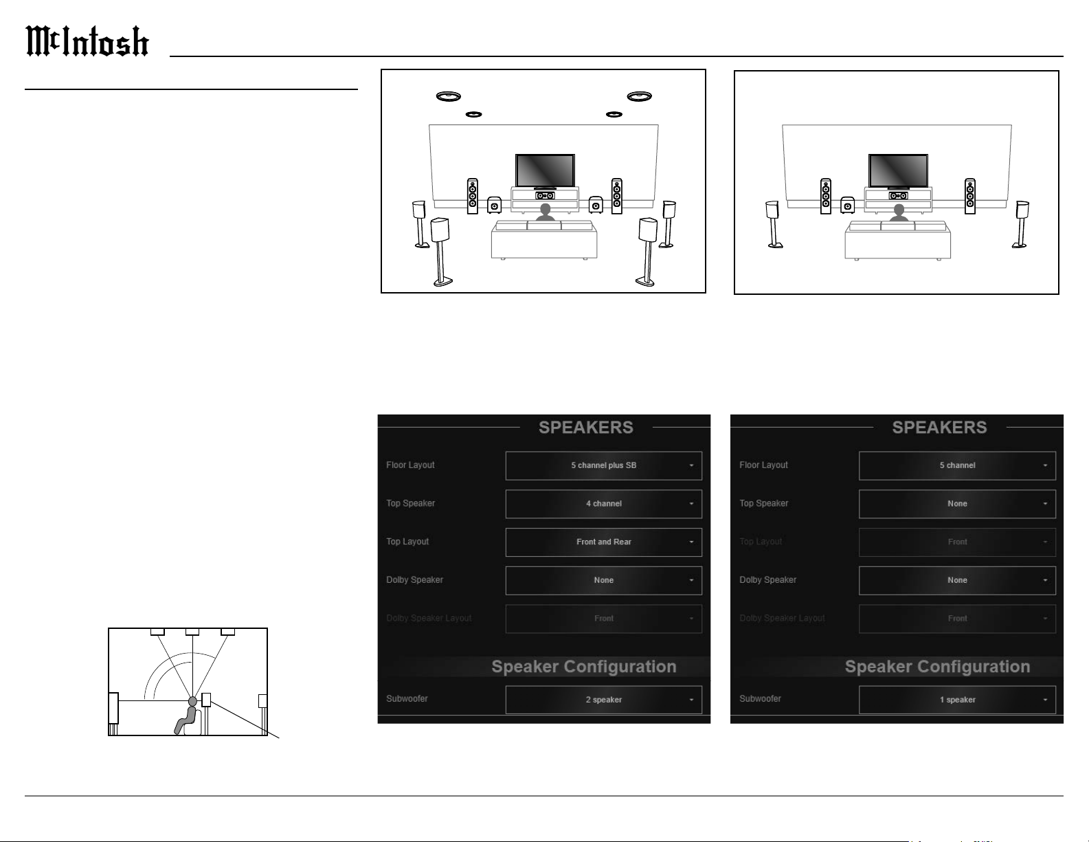
Setting up speakers for a surround setup takes
planning, measuring and installation. Depending on
wish to employ the services of your McIntosh dealer
due to gravity and the location above your head.
The number, types and locations of speakers are
key elements in setting up the system. There is a
Often surround setups are referred to by numbers
and surround). The second number is the number
of subwoofers that can be connected, and the third
The type of speaker (size and location) will be
entered later during Speaker setup. The distance of
the speaker from the listening location is manually
entered in the Speaker setup, or automatically entered
during the Dirac Live
to the various speakers, powered subwoofers, and
®
calibration process.
H2-L H2-R
H1-L H1-R
3-L 5-R
2-LS 6-RS
SW -1
1-LB 7-R B
4-C
SW-2
7.2.4 with Front & Rear Tops
four ceiling mounted speakers. The settings from the
browser setup menu are shown below.
3-L 5-R
2-LS 6-RS
SW -1
4-C
5.1
The settings from the browser setup menu are shown
below.
Front speaker
Top middle speaker
Top front speaker Top rear speaker
∗4
∗3
∗2
Surround
back speaker
(Viewed from the side)
Surround
speaker
∗4 125° - 150°∗2 30° - 55° ∗3 65° - 100°
Page 25
GOOD
ART
2-LS 6-RS
1-LB 7-R B
3-L 5-R
4-C
2-LS 6-RS
1-LB 7-R B
3-L 5-R
4-C
SW -1
SW-2
SW -1
SW-2
GOOD
ART
H1-L H1-R
H2-L H2-R
3-L 5-R
2-LS 6-RS
1-LB 7-R B
3-L 5-R
4-C
SW -1
SW-2
GOOD
H1-L H1-R
H2-L H2-R
2-LS 6-RS
1-LB 7-R B
3-L 5-R
4-C
SW -1
SW-2
GOOD
ART
H1-L H1-R
H2-L H2-R
MX200
H2-L H2-R
H1-L H1-R
2-LS 6-RS
1-LB 7-R B
4-C
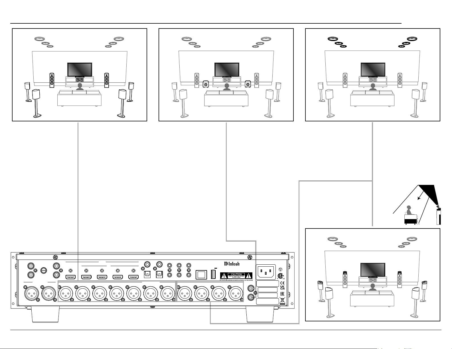
Floor Speakers
connect to speakers around the room via your
SW -1
SW-2
Subwoofers
Your surround sound setup might include one or
two subwoofers. Use the SW1 and SW2 outputs on
Heights
for up to four Dolby Atmos speakers. Dolby Atmos
to allow the sound to come from over your head by
Note: RH1 and LH1 should be forward of
RH2 and LH2.
MM
L
R
BALANCED IN
AUX 2R AUX 2L
AUX 1
GND
L
OUT/eARC
R
1 2
RF LF C LS RB LB RH1RS LH1 RH2 LH2
HDMI
IN
3
1
4
BALANCED OUT
2
RS232
COAX
2
1
OPT
DIGITAL INPUTS
TRIG 1 IR IN
SETUP MIC
TRIG 2
DATA OUT
SERVICE
USB
5V/1A
NET
McINTOSH LABORATORY, INC., BINGHAMTON, NY
HANDCRA FTED IN US A WIT H US AND I MPOR TED PAR TS
MX200
A/V PR OCES SOR
UNBAL OUT
SW1
SW2
MAC ID
MAC ID
SERIAL
NUMBER
H1-L H1-R
H2-L H2-R
Page 26

Audio Specications
Video Specications
General Specications
Note: the MX200 specifications are with Dirac Live bypassed.
Frequency Response
Total Harmonic Distortion
Signal To Noise Ratio - A Weighted
High Level: 96dB below rated Output
Output Impedance
Input Impedance
High Level: 22k Ohms Unbalanced and Balanced
Sensitivity for Rated Output
Maximum Voltage Output
Maximum Input Signal
Room Correction
Dirac Live
HDMI (Inputs and Outputs)
Fixed Rate Link (FRL)
Video Resolution
HDCP
Version 2.3
Coaxial/Optical Digital Input Rate and Formats
Dolby Digital, DTS
HDMI Input Rate and Formats
Atmos, Dolby TrueHD, Dolby Digital Plus,
Note: the MX200 has been tested and certified for indoor use only.
Power Requirements
Note: Refer to the rear panel of the MX200 for the correct voltage.
Overall Dimensions
Weight
Shipping Carton Dimensions
Power Control Output
Trademarks of McIntosh Laboratory, Inc.:
TripleView; Made of Sound.
26
Page 27
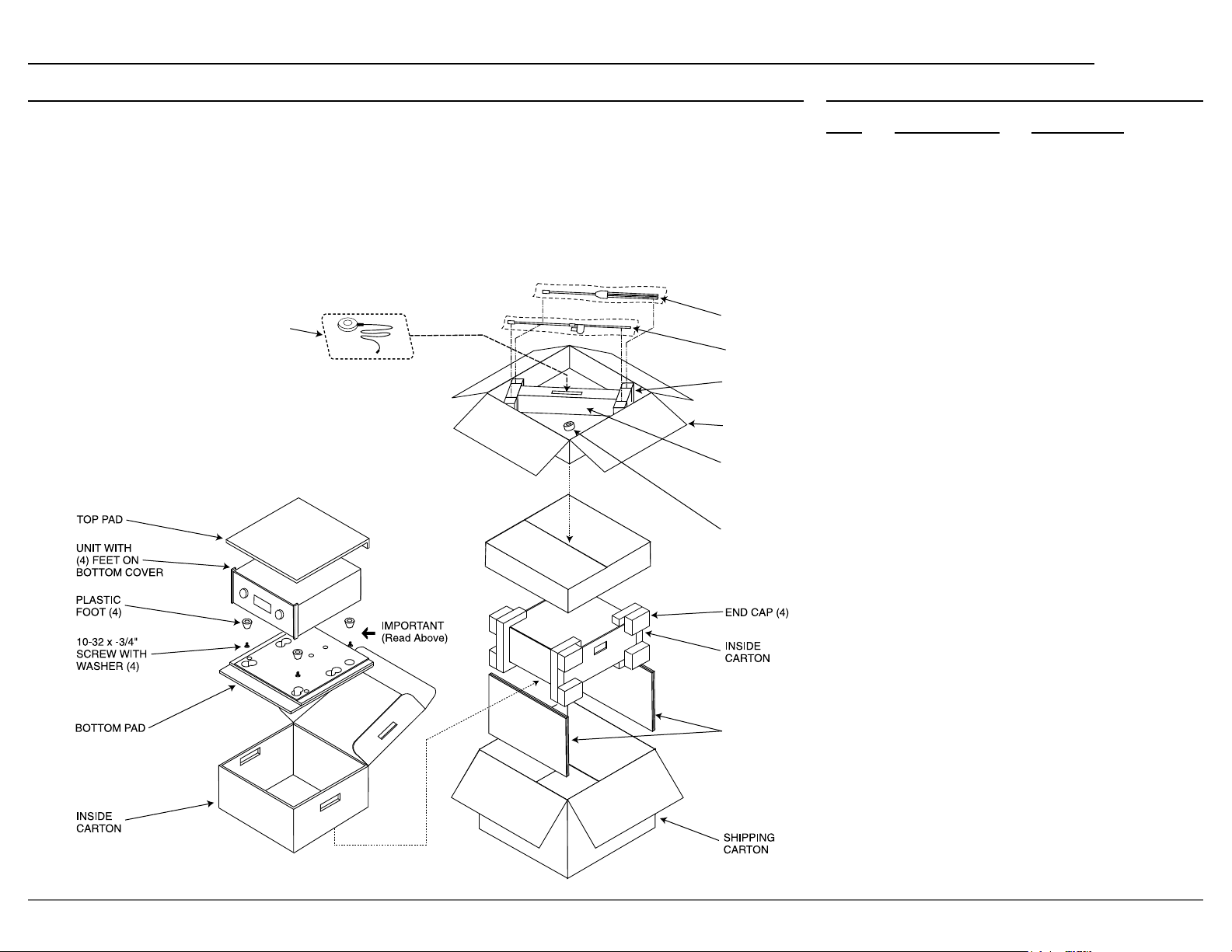
Packing Instructions Part List
MX200
as shown below.
It is very important that the four plastic feet
are attached to the bottom of the equipment.
This will ensure the proper equipment location
on the bottom pad. Failure to do this will result in
shipping damage.
MICROPHONE
AND CABLE
Use the original shipping carton and interior parts
only if they are all in good serviceable condition.
If a shipping carton or any of the interior part(s)
Department of McIntosh Laboratory. Refer to page 2.
Please see the Part List for the correct part numbers.
MICROPHONE
STAND
MINI BOOM
SLOTTED
FOAM (2)
ACCESSORY
BOX
DIVIDER
FOAM
MICROPHONE
ADAPTER
Qty Part Number Description
SPACER
PADS
Page 28

McIntosh Laboratory, Inc.
2 Chambers Street
Binghamton, NY 13903
www.mcintoshlabs.com
The continuous improvement of its products is the
policy of McIntosh Laboratory, Inc. who reserve
the right to improve design without notice.
Printed in the U.S.A.
© 2024 McIntosh Laboratory, Inc.
McIntosh Part No. 24123400
 Loading...