

Page 1
McIntosh Laboratory, Inc. 2 Chambers Street Binghamton, New York 13903-2699 Phone: 607-723-3512 www.mcintoshlabs.com
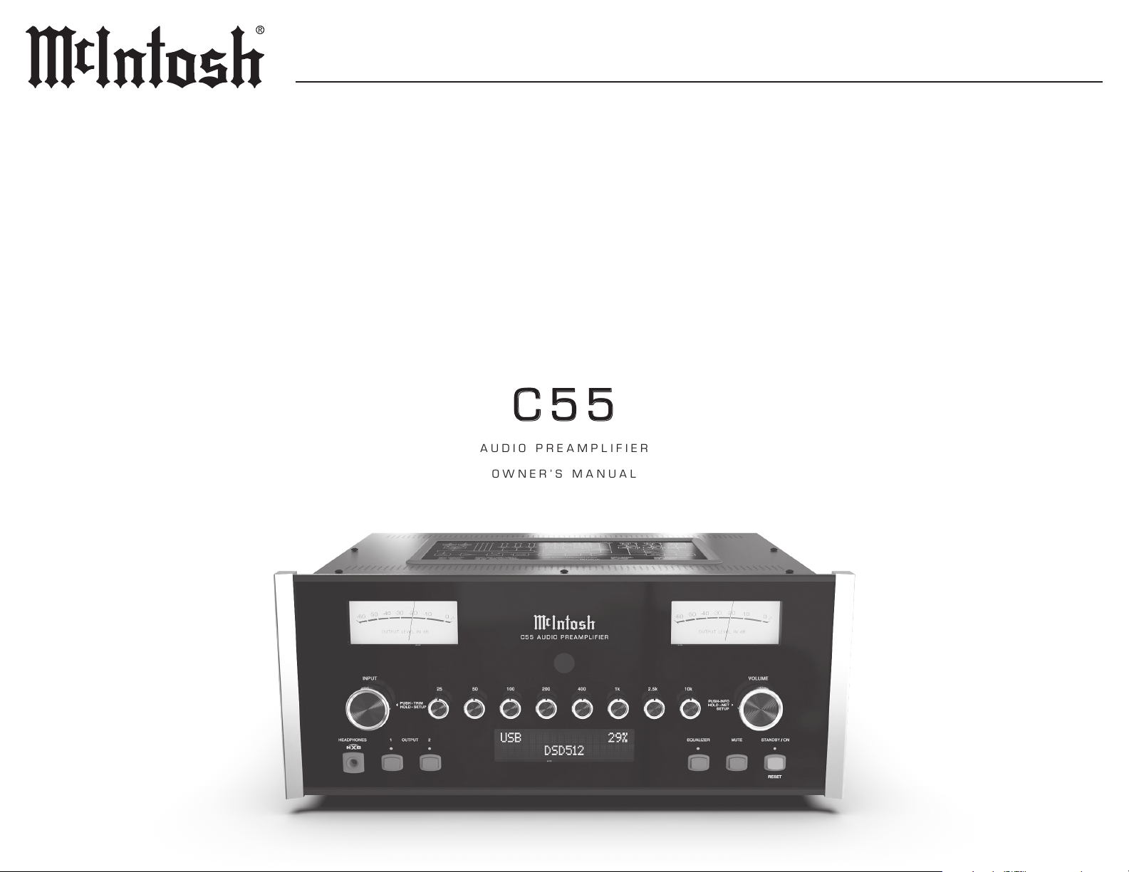
AUDIO PREAMPLIFIER
OWNER’S MANUAL
Page 2
Thank You from all of us at McIntosh
Table of Contents
Trademark and License Information
You have invested in a precision instrument that
will provide you with many years of enjoyment.
Please take a few moments to familiarize yourself
with the features and instructions to get the
maximum performance from your equipment.
If you need further technical assistance, please
contact your dealer who may be more familiar with
your particular setup including other brands. You
can also contact McIntosh with additional questions
or in the unlikely event of needing service.
McIntosh Laboratory, Inc.
2 Chambers Street
Binghamton, New York 13903
Technical Assistance (607) 723-3512
Fax (607) 724-0549
Customer Service (607) 723-3515
Fax (607) 723-1917
Email [email protected]
Website www.mcintoshlabs.com
Please Take A Moment
For future reference, you can write down your
serial number and purchase information here. We
can identify your purchase from this information if
the occasion should arise:
General Information .. .. .. .. .. .. .. .. .. .. 3
Connector and Cable Information.. .. .. .. .. 3
Performance Features .. .. .. .. .. .. .. .. .. .. 4
Dimensions .. .. .. .. .. .. .. .. .. .. .. .. .. .. 5
Installation .. .. .. .. .. .. .. .. .. .. .. .. .. .. 5
Front Panel Knobs and Buttons.. .. .. .. .. .. 6
Inputs .. .. .. .. .. .. .. .. .. .. .. .. .. .. .. .. 7
Outputs.. .. .. .. .. .. .. .. .. .. .. .. .. .. .. .. 7
How to use the Remote Control .. .. .. .. .. .. 9
Setup Menus . .. .. .. .. .. .. .. .. .. .. .. .. ..10
Digital Setup Menu .. .. .. .. .. .. .. .. .. .12-13
Inputs Setup Menu .. .. .. .. .. .. .. .. .. .. ..13
Outputs Setup Menu .. .. .. .. .. .. .. .. .. .. 14
Triggers Setup Menu .. .. .. .. .. .. .. .. .. ..15
Data Out Setup Menu .. .. .. .. .. .. .. .. .. ..15
External Control Setup Menu. .. .. .. .. .. ..16
System Configurations .. .. .. .. .. .. .. .. .. 17
Connecting Components.. .. .. .. .. .. .. .. .. 17
Network Information Menu .. .. .. .. .. .. ..18
Trim Functions Menu .. .. .. .. .. .. .. .. .18 -19
Equalizer Controls .. .. .. .. .. .. .. .. .. .. ..19
How to Operate the C55 .. .. .. .. .. .. .. 20-21
Specifications .. .. .. .. .. .. .. .. .. .. .. .. ..22
Packing Instructions .. .. .. .. .. .. .. .. .. ..23
Parts List .. .. .. .. .. .. .. .. .. .. .. .. .. .. ..23
The McIntosh C55 incorporates copyright protected technology that is protected by U.S. patents and
other intellectual property rights. The C55 uses the
following technologies:
Trademark License Information
ASIO is a trademark and software
of Steinberg Media Technologies
GmbH
Manufactured under license
from Dolby Laboratories. Dolby,
Dolby Audio, and the double-D
symbol are trademarks of Dolby
Laboratories.
For DTS patents, see http://patents.
dts.com. Manufactured under
license from DTS, Inc. DTS, the
Symbol, DTS and the Symbol
together, and Digital Sur round
are registered trademarks and/
or trademarks of DTS, Inc. in
the United States and/or other
countries. DTS, Inc. All Rights
Reserved.
The terms HDMI, HDMI
High-Denition Multimedia
TM
Interface, and the HDMI Logo
HIGH-DEFINITION MULTIMEDIA INTERFACE
are trademarks or registered
trademarks of HDMI Licensing
Administrator, Inc.
Serial Number: __________________________
Purchase Date: ___________________________
Dealer Name: ___________________________
2
Safety First
Please read the safety instructions included in a
separate document called Important Additional
Operation Information Guide.
Page 3

PIN 3
PIN 3
General Information
Ground
Ground
C55
Connector and Cable Information
1. Do not apply AC Power to the C55 and other
Component(s) until they are connected to the
C55 so operational malfunctioning does not
occur.
2. Balanced and Unbalanced Inputs and Outputs
can be mixed. For example, you may connect
signal sources to Unbalanced Inputs and send
signals from the Balanced Outputs. You can
also use Balanced and Unbalanced Outputs
simultaneously, connected to different Power
Ampliers.
3. The C55 internal Digital to Analog Converter
Circuitry is designed to decode PCM, DSD
and DTS Digital Signals. The Coaxial and
Optical Digital Audio Inputs are for PCM
Digital Signals, Dolby Signals and DTS Signals.
The C55 also decodes USB and HDMI (ARC)
Digital Signals. Other Digital Audio Signal
Format Types will cause the Audio Outputs of
the C55 to be muted.
4. The McIntosh C55 is factory congured for
immediate use. It can also be customized to
complement the components making up your
system. Refer to the Setup Menu described on
page 11.
5. The Remote Control Supplied with the C55
Preamplier is capable of operating other
components. For additional information go to
www.mcintoshlabs.com.
6. The IR Input is congured for non-McIntosh
IR sensors such as a Xantech Model HL85BK
Kit. Use a Connection Block such as a Xantech
Model ZC21 when two or more IR sensors need
to be connected to the C55. The signal from a
connected External IR Sensor will have priority
over the signal from the Front Panel IR Sensor.
7. For additional information on the C55 and other
McIntosh Products please visit the McIntosh
website at www.mcintoshlabs.com.
Introduction
The McIntosh C55 Audio Preamplier is one of
the nest Preampliers ever created with connec
tions for both analog and digital sources. The C55
Outputs have the ability to drive multiple Power
Ampliers. The C55 reproduction is sonically
transparent and absolutely accurate. The McIntosh
Sound is “The Sound of the Music Itself.”
-
XLR Connectors
Pin conguration for the XLR Balanced Input
and Output Connector. Refer to the diagrams for
connections:
PIN 1: Shield/Ground
PIN 2: + Input/Output
PIN 3: - Input/Output
PIN 2 PIN 1
PIN 1
PIN 2
Power Control and Trigger Connectors
The C55 Power Control Out, Trigger
and Passthru Output Jacks send
Power On/Off Signals (+12 volt/0
volt) when connected to other
Components. An additional connec
tion is for controlling McIntosh Power Ampliers
Output Meters. A 3.5mm stereo mini phone plug is
used for connection to the Power Control (Trigger)
and Passthru Output.
Note: The Six Foot Cables are available from the McIntosh Parts
Department. Part No. 170202.
Main, Triggers 1- 4
and Passthru
Power
Control
Meter
Illumination
Control
-
Data Port Connectors
The C55 Data Out Ports send
Remote Control Signals to Source
Components. A 3.5mm stereo mini
phone plug is used for connection.
Data
Signal
N/C
Data
Ground
IR IN Port Connectors
The IR IN Port also uses a 3.5mm
stereo mini phone plug and allows
the connection of other brand IR
Receivers to the C55.
IR Data
Control
N/C
RS232 Data Port Cable
The RS232-C Data Cable is a 3.5mm stereo mini
phone plug used to connect
to external third party
controllers.
C55 TXD Out
Data being transmitted
C55 RXD In
Data being received
Ground
3
Page 4

Performance Features
• Electromagnetic Input Switching with
Level Trim Adjustment
Digital Logic Circuits drive Electromagnetic
Switches on all Inputs and operating functions for
reliable, noiseless, distortion-free switching. The
Analog Inputs can be matched in level, preventing
abrupt changes in volume levels.
• Phono Inputs with Adjustable Gain
The C55 has two precision Phono Preamplier
Circuits. They have the ability to be congured
for Moving Coil or Moving Magnet Cartridges.
The close tolerance resistors and capacitors used
in the RIAA Correction Equalization Circuitry
provide an extremely at frequency response.
• Selectable Phono Cartridge Loading
Adjustable Capacitance and Resistance Loading
are available for both Moving Coil and Moving
Magnet Phono Cartridges. Capacitance Loading
is selectable from values of 50 picofarads to 400
picofarads. Resistance Loading is selectable from
values of 25 ohms to 47,000 ohms.
• Digital Audio Inputs
The Digital Inputs decode PCM and DSD
Signals from external sources. Coaxial, Optical
and HDMI Inputs process Digital Signals
up to 192kHz with 24-Bit resolution. The
Digital MCT Input Circuitry directly decodes
SACD/CD signals from an external Transport
component. The USB Input for streaming audio
processes Digital Signals up to 384kHz with
32Bit resolution, decodes up to DSD512 Digital
Signals and DXD 24Bit with a sampling rate up to
384kHz.
• Balanced Inputs
The Balanced Inputs allow the connection of
a source component using long cable lengths
without a loss in sound quality.
• Precision Tracking VOLUME Knob
Volume levels are controlled by a Precision
Balanced Digitally Controlled Attenuator System
with an Encoder Rotary Control. This assures a
0.1dB tracking accuracy between channels. There
are 214 individual 0.5dB volume level steps with
no noise as the volume level is changed.
• Variable Rate Volume and Balance Controls
The C55 Preamplier’s Volume and Balance
Control Circuitry provides an ideal rate of change
with control rotation.
• Equalizer Controls
The eight Front Panel Equalizer Controls provide
12dB of boost or cut at their center frequencies.
The C55 remembers the Equalizer Circuitry ON/
OFF Setting for each input.
• HXD® for Headphones
The C55 Headphone Crossfeed Director Circuitry
(HXD
Headphone Listening. HXD
directionality component of the spatial sound
stage normally heard with loudspeaker listening.
®
) improves the sound localization for
TM
restores the
• Alphanumeric Fluorescent Display
The Front Panel Information Display indicates
the Source Selection, Volume/Balance Levels and
Setup Menu Selections. The display intensity is
adjustable.
• Passthru Mode
The Automatic Passthru Mode allows the C55
to become part of a Home Theater Multichannel
Sound System.
• Remote Control with External Sensor Input
The Remote Control provides control of the
C55 operating functions and McIntosh Source
Components connected to it. Enjoy your McIntosh
System from another room in your home by
connecting an external sensor.
• Power Control Output and Trigger
Assignment
A Power Control connection for convenient
Turn-On of McIntosh Power Ampliers, Source
Components and Accessories is included. The
Power Control Trigger Outputs may be assigned
to activate when a given Input/Output is selected.
• Special Power Supply
Fully regulated Power Supplies and a special
R-Core Power Transformer ensure stable, noisefree operation even though the power line varies.
• Glass Front Panel with LED Illumination
The famous McIntosh Glass Front Panel is evenly
Illuminated by multiple extra long life Light
Emitting Diodes (LEDs) arranged with a special
orientation. The pristine beauty of the C55 will be
retained for many years.
• Bi-Amp Outputs
Built-in Adjustable Highpass and Lowpass
Outputs for bi-amping your speaker system.
4
HXD® is a registered trademark of McIntosh Laboratory, Inc.
Page 5
Dimensions
C55
Installation
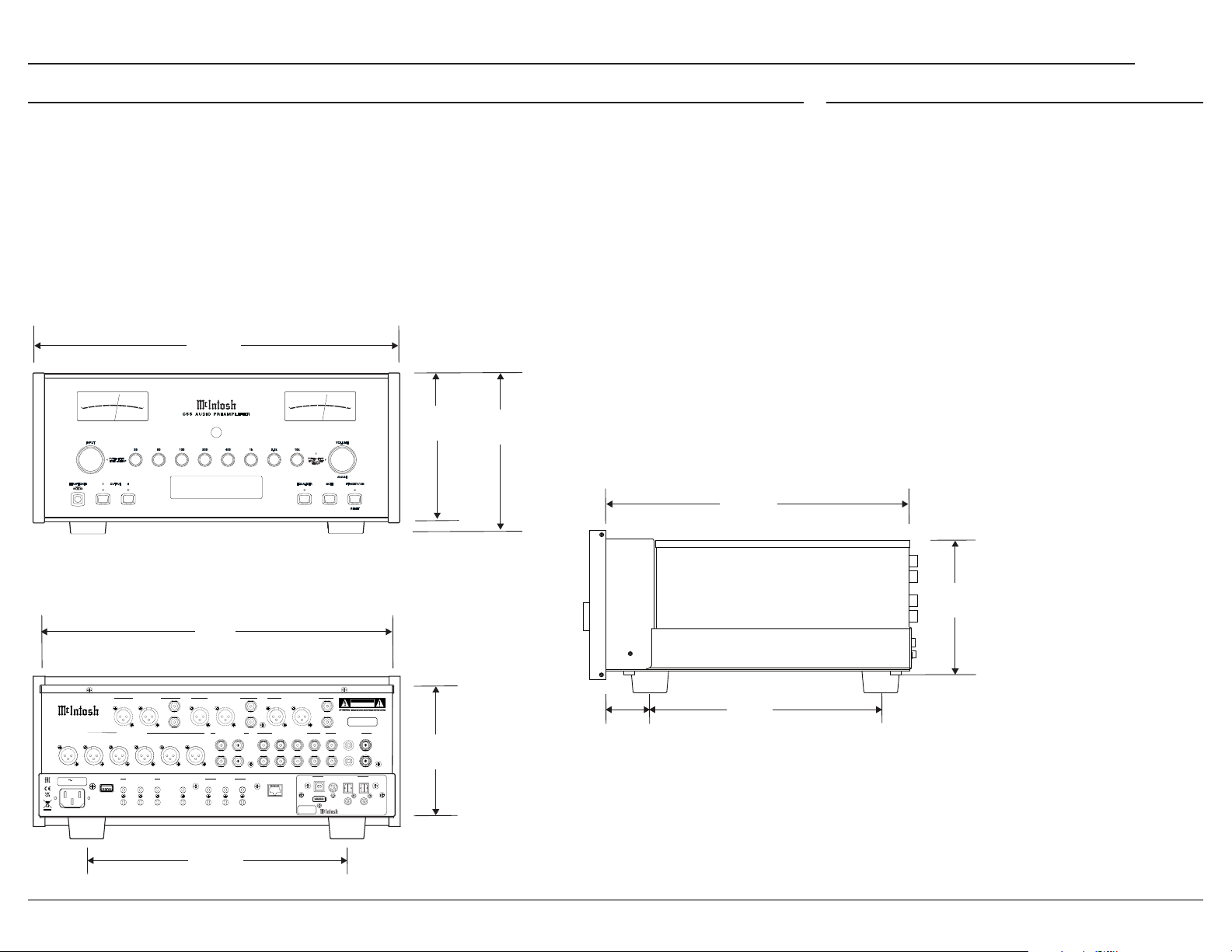
The following dimensions can assist in determining the best location for your C55. There is additional
information on the next page pertaining to installing the C55 into cabinets.
A Note on Placement:
It is important to keep your McIntosh unit out of direct sunlight and only use appropriate gentle cleaners
because the Organic Anodize can become discolored over time.
While most products will maintain their classic dark features for their lifetime, some situations can
accelerate discoloration. The most pervasive culprit is UV light, especially light directly from the sun, or
high intensity spotlights. Even high intensity short-term exposure can result in discoloration.
Chemicals can also alter the nish of the Anodize. Aggressive cleaners will take their toll over time and
actually etch away the Anodize nish.
17 ⁄”
44.5 cm
-30
-60
-60
-40
-40
-50
-50
OUTPUT LEVEL IN dB
OUTPUT LEVEL IN dB
EQUALIZER
PUSH – INFO
HOLD – N ET
-30
-20
-20
-10
-10
0
0
+3
+3
VOLUME
SETUP
DJUST
A
/
STANDBY ON
MUTE
RESET
7 ⁄”
18.1 cm
7 ⁄”
19.4 cm
14 ⁄”
36.8 cm
HEADPHONES
-60
-60
-50
-50
INPUT
-30
-30
-20
-20
-40
-40
-10
-10
0
0
+3
+3
OUTPUT LEVEL IN dB
OUTPUT LEVEL IN dB
25 5 0 100 200 400 1 k 2.5k 10k
PUSH - TRIM
HOLD - SETUP
OUTPUT
1 2
C5 5 A UD IO P R EA M PL I FI E R
USB 35%
DSD256
The C55 should be installed upright on its four feet.
Adequate ventilation is important and will aid in a
long trouble-free life of the C55. You must ensure
proper airow by allowing at least 3 inches (7.6cm)
above the unit and 3 inches (7.6cm) for the front,
rear and sides. Do not remove the feet to ensure
adequate airow beneath the C55. There must be
openings for cool air to enter (below) and warm air
to escape (above) the C55.
MAIN / HIGH PASS OUTPUT 1 / LOW PASS
C55 P REA MP LI FIE R
McINTOSH LABORATORY, INC. BINGHAMTON, NY
HANDCRAFTED IN USA WITH US AND IMPORTED PARTS
1R 1L 2R 2L 3R 3L
120V 50/60Hz
75 WATTS
BAL R BAL L BAL R BAL L
BALANCED INPUTS PROCESSOR LOOP
POWER CONTROL
TRIG 3
TRIG 1
SERVICE
PORT
TRIG 2
TRIG 4
17 ⁄”
43.5 cm
INSIDE DIMENSION
OUTPUT 2 (SUBWOOFER)
L
UNBAL UNBAL UNBAL
R
EXTERNAL CONTROL DATA PORTS
MAIN
PASSTHRU
RETURN
IR IN
1
3
4
RS232
2
BAL R BAL L
L
R
UNBALANCED INPUTS
1 42
SEND
L
R
NETWORK
5
CONTROL / UPDATE
ONLY
6
13 ⁄”
33.7 cm
6 ⁄”
16.5 cm
CAUTION
RISK OF ELECTRIC SHOCK
DO NOT OPEN
L
SERIAL
R
3
USB AUDIO
HDMI (ARC)
SERIAL
NUMBER
1
L
R
DIGITAL AUDIO INPUTS
MCT OPTICAL 2 OPTICAL 1
DA2 DIGITAL AUDIO MODULE
2
GND
6 ⁄”
16 cm
COAX 2
COAX 1
NUMBER
PHONO INPUTS
1
⁄”
4.9 cm
10 ⁄”
26.8 cm
5
Page 6
-50
-50
-60
-60
-30
-30
-20
-20
-40
-40
OUTP UT LE VEL IN dB
OUTP UT LE VEL IN dB
-30
-30
-20
-20
-40
-10
-10
0
0
+3
+3
C 55 A UD I O P R E A M PL I F I E R
-50
-50
-60
-60
-40
OUTP UT LE VEL IN dB
OUTP UT LE VEL IN dB
-10
-10
0
0
+3
+3
INPU T
PUSH - TR IM
HOLD - SE TUP
HEADP HONES
OUTPU T
1 2
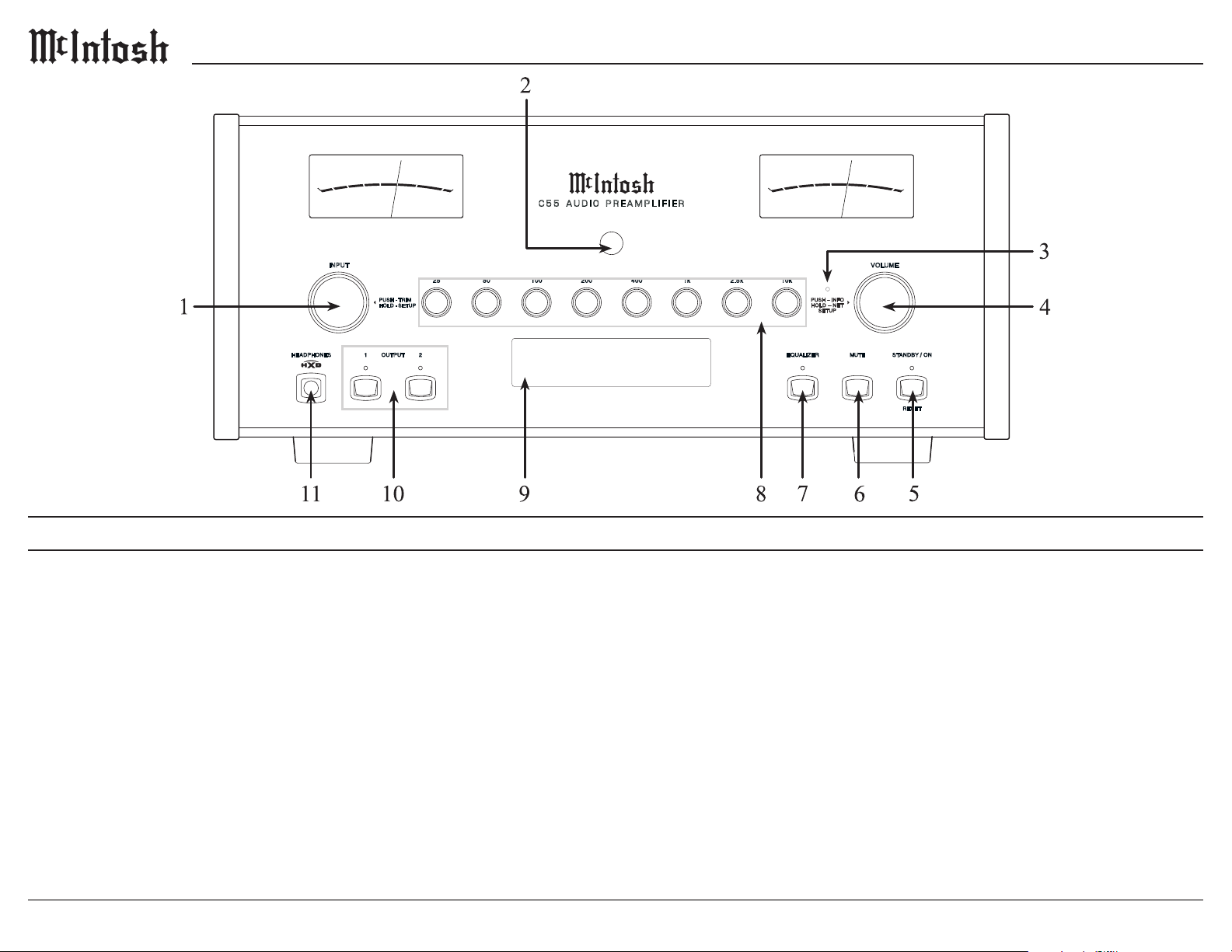
Front Panel Knobs and Buttons
1. INPUT Knob is used to select a source for
listening and recording. The knob is also used for
menu navigation.
2. IR Sensor receives commands from a Remote
Control.
3. NETwork Status LED provides NET connection
status.
4. VOLUME Knob allows adjustment of the
listening level for both channels, Trim Mode
Adjustments, and various SETUP Functions.
25 50 100 200 400 1k 2.5k 10k
USB 35%
DSD256
5. STAN DBY/ON Button with indicator switches
the C55 ON or OFF (Standby) and resets the
microprocessors.
6. MUTE Button mutes the audio from the
loudspeakers and Headphones.
7. EQUALI ZER Button allows the user to select
whether or not the equalizer circuit is engaged. In
the Off mode, the front panel adjustment knobs
are bypassed and the audio signal is unaltered. In
the On mode, the audio signal can be adjusted via
the front panel frequency knobs.
VOLU ME
PUSH – IN FO
HOL D – N ET
SETUP
/
EQUALIZER
MUTE
STANDBY ON
RESET
8. Eight Band Equalizer Knobs allow the user
to boost or cut any individual frequency or any
combination of frequencies. Refer to Equalizer
Controls on page 19.
9. Information Display indicates the Sources,
Volume, other Audio Settings, Operational
Functions and Setup Menu Settings
10. OUTPUT 1 and 2 Buttons with indicators switch
the Preamplier Outputs 1 and 2 On or Off.
11. HEADPHONES Connection to use with low
impedance dynamic headphones for private
listening.
6
Page 7
C55
C5 5 PR EAM PL IF IER
McINTOSH LABORATORY, INC. BINGHAMTON, NY
HANDCRAFTED IN USA WITH US AND IMPORTED PARTS
BALANCED INPUTS PROCESSOR LOOP
1R 1L 2R 2L 3R 3L
120V 50/60Hz
75 WATTS
SERVICE
PORT
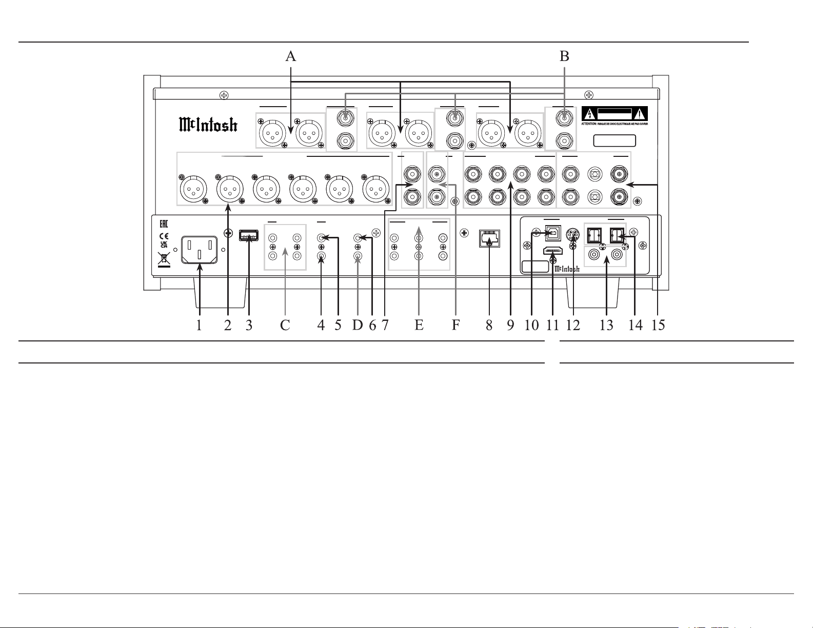
Inputs
1. AC Input uses a power cord to connect to an AC Outlet.
2. BALANCED INPUTS (1 thru 3) accept high-level
program source signals.
3. SERVICE USB is a USB Type-A port used for service
purposes only.
4. POWER CONTROL Passthru receives On/Off signals
from an Audio/Video Processor.
5. POWER CONTROL MAIN sends On/Off signals to
a McIntosh Component when the C55 Preamplier is
switched On/Off.
6. IR IN accepts an external IR receiver using a 3.5mm stereo
mini phone plug cable.
7. PROCESSOR LOOP RETURN receives audio from an
external equalizer or room correction processor.
8. NETWORK for a wired internet connection via ethernet.
9. UNBALANCED INPUTS (1 thru 4) accept high-level
program source signals.
MAIN / HIGH PASS OUTPUT 1 / LOW PASS
BAL R BAL L BAL R BAL L
POWER CONTROL
TRIG 3
TRIG 1
TRIG 2
TRIG 4
L
UNBAL UNBAL UNBAL
R
RETURN
EXTERNAL CONTROL DATA PORTS
MAIN
PASSTHRU
IR IN
RS232
1
2
L
R
SEND
L
R
5
3
4
6
BAL R BAL L
UNBALANCED INPUTS
1 42
NETWORK
CONTROL / UPDATE
ONLY
10. USB AUDIO Input is a USB Type-B connector used to
connect the C55 to a computer to stream digital audio.
11. HDMI (ARC) Input connects with a compatible ARC TV
using an HDMI cable to share control and digital audio
connectivity.
Note: The HDMI ARC functionality of the C55 is only compatible
with ARC TVs. Other devices like DVD and Blu-ray players
will not work.
12. MCT Input transfers signals from McIntosh
products with an MCT connector and is required for
SACD audio.
13. COAX Inputs (1 and 2) accept coaxial cables for
digital signals.
14. OPTICAL Inputs (1 and 2) accept optical
connections for digital signals.
15. PHONO Inputs (Right and Left channels) accept
signals from a Phono Cartridge.
OUTPUT 2 (SUBWOOFER)
3
HDMI (ARC)
SERIAL
NUMBER
CAUTION
RISK OF ELECTRIC SHOCK
L
R
1
L
R
DIGITAL AUDIO INPUTS
USB AUDIO
MCT OPTICAL 2 OPTICAL 1
DO NOT OPEN
SERIAL
NUMBER
PHONO INPUTS
DA2 DIGITAL AUDIO MODULE
GND
COAX 2
2
COAX 1
Outputs
A. BALanced Outputs each use an XLR
connector cable for a balanced output signal.
B. UNBALanced Outputs use an RCA connector
cable for an unbalanced output signal.
C. POWER CONTROL TRIG (1 thru 4) send
On/Off signals to other McIntosh components.
D. RS232 Connector communicates with external
control devices using a 3.5mm stereo mini
phone plug cable.
E. DATA PORTS retransmit remote control
signals to source components.
F. PROCESSOR LOOP SEND jack delivers
audio to an external equalizer or room
correction processor.
7
Page 8
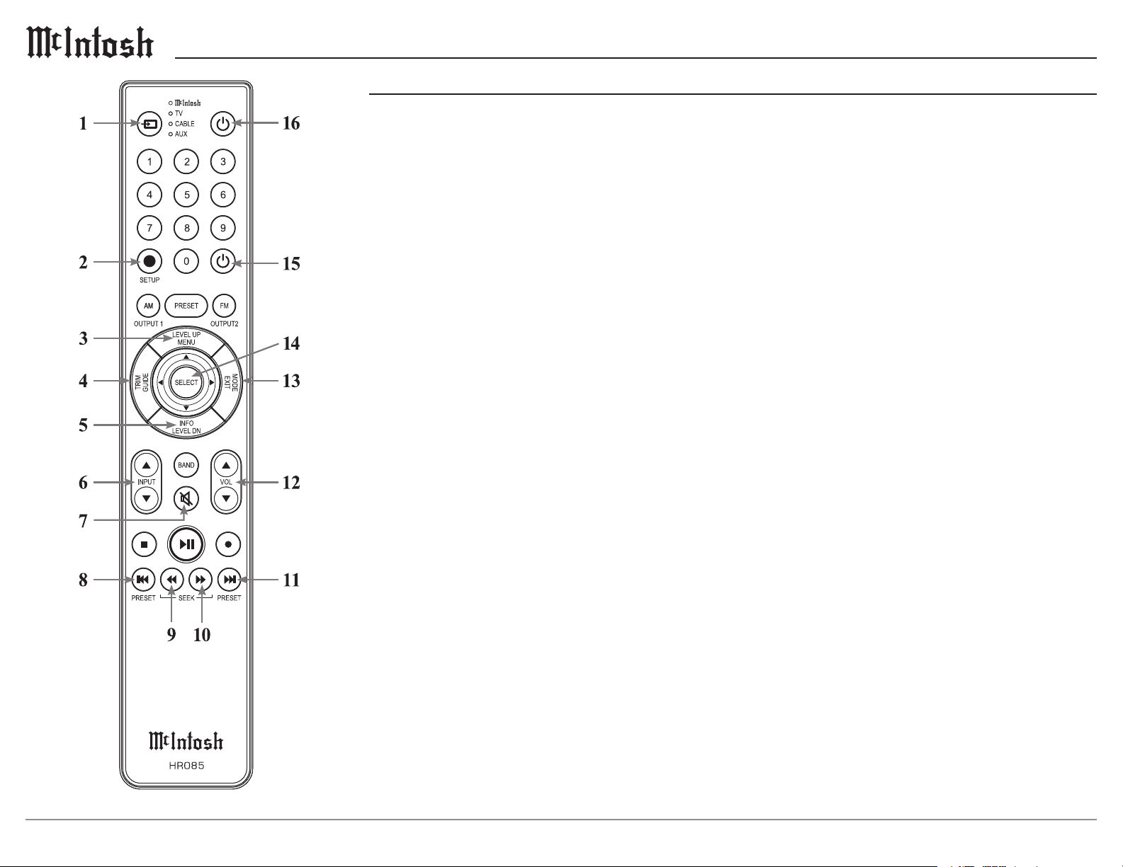
Navigating the Remote Control
1. Switch Device: Select different devices for remote
operation. Selected device is indicated by the LED
indicator.
2. Setup Button: Used to enter Setup Menu.
3. Level Up/Menu: Adjusts Trim Functions settings.
Accesses menu on compatible devices.
4. Tr im/Guide: Enters Trim Functions menu. Opens
guide on compatible devices.
5. Info/Level Down: Adjusts Trim Functions
settings. Accesses info on compatible devices.
6. Input: Changes and selects different inputs.
7. Mute: Mutes audio playback.
8. Previous/Previous Preset: Return to your previ
-
ous media selection.
9. Fast Reverse/Seek Down: Navigate backwards
through the current active media using this button.
10. Fast Forward/Seek Up: Navigate forward
through the current active media using this button.
11. Next/Next Preset: Jump to your next media
selection or navigate to the next tuner preset.
12. Volume: Used to adjust the volume.
13. Mode/Exit: This will exit the Trim Functions
menu. It will also display information or certain
options.
14. Select: Selects the highlighted option.
15. Power Off: Turns off the selected device shown
by the LED.
16. Power On: Turns on the selected device shown by
the LED.
Note: The HR085 Remote Control has buttons used to control
multiple devices. Buttons whose function are not described are
for use with other McIntosh products.
For more information, refer to the HR085 Owner's Manual on
the McIntosh website at www.mcintoshlabs.com.
Remote Control Batteries
The HR085 Remote Control included with the C55
is powered by two AAA batteries (not included).
To insert or remove batteries, open the battery
compartment by removing the cover located on the
back of the remote control. To open, pull the clasp
located just above the opening downward.
Additional Discrete Commands
Additional discrete commands for external
control systems are available:
• BAL 1, 2, 3
• UNBAL 1, 2, 3, 4
• PHONO 1, 2
• COAX 1, 2
• OPT 1, 2
• USB
• MCT
• HDMI
• Power (Cycle)
These additional commands can be accessed
using an optional McIntosh HR093 Service Remote
Control. A list of these commands as well as
Pronto Hex Codes can be found in the C55 Pronto
Hex Codes document located in the Download
section of the C55 product information at
www.mcintoshlabs.com
You can also contact McIntosh Technical
Assistance or your dealer for more information.
8
Page 9
C55
How to use the Remote Control
The supplied C55 Remote Control (HR085) is
capable of directly controlling the functions of
contemporary McIntosh Source Components
connected to the C55 via the Data Ports.
Notes: 1. If at any time the C55 seems unresponsive to the HR085
Remote Control Commands, press the DEVICE Button
to select first.
2. For additional information on using the HR085 Remote
Control with the McIntosh Model, please refer to the “How
to Operate” starting on page 20.
3. For additional information on assigning the Data Ports,
refer to “Data Ports” on page 13.
Trim
Press the TRIM Button until the desired Trim
function (Balance, Trim Level, etc.) appears on the
C55 Front Panel Display, then press the LEVEL Up
or Down Button to adjust the Trim setting.
Note: Press the TR IM Button to recall the last Trim function
selected. For additional information on using the Trim
Functions refer to pages 18-19.
Output Selection
Press the BLUE (Setup) Button followed by the
AM (Output 1) or FM (Output 2) Button, to control
the Rear Panel Audio OUTPUTS 1, 2 (ON or OFF)
and Power Control TRIG 1 / TRIG 2.
Note: For additional information on assigning the Outputs (1 and
2) and Power Control Triggers (1 and 2) refer to page 3.
The supplied HR085 Remote Control is capable of
directly controlling the functions of contemporary
Source Components connected to the C55 via the
Data Ports.
Note: If at any time the C55 seems unresponsive to HR085 Remote
Control Commands press the
Button first.
Mute
Press the MUTE Button to mute the audio in all
outputs except the SEND OUTPUT. The word
MUTE will appear on the Front Panel Information
Display. To un-mute the audio, press the MUTE
Button again.
Disc, Server and Tape Functions
Use these buttons to operate a DVD Player, CD
Player, CD Changer, Music Server or Recorder.
Numbered Buttons
Press Buttons 0 through 9 to access tuner station
presets, tracks on discs or selections on a Music
Server.
Disc and Track
Use the AM (disc) and FM (track) Buttons when a
Disc Player or Music Server is being used.
Tun e r Bu t t ons
Press the AM or FM Button to select the desired
broadcast band. Press and release the Channel Up
p or Down q Button to seek the next available
station. Press and hold a Channel Up p or Down
q Button to seek continuously from station to
station.
Volume
Press the Up p or Down q VOLUME Button to
raise or lower the listening volume level.
Note: The Record Signals present at REC OUTPUTS are not
affected by volume changes.
Pause
Press the Pause Button to perform various
functions on a variety of McIntosh Components. It
will also pause the playing of a disc or tape player.
Trim
Press the TRIM Button until the desired Trim
function (Balance, Trim Level, etc.) appears on
the Front Panel Information display, then press the
LEVEL Up p or Down q Button to adjust the
Trim setting.
Note: Press the TR IM Button to recall the last Trim Function
selected. For additional information on the Trim Functions
refer to pages 18 and 19.
Amplier Selection
Press the BLUE (Setup) Button followed by the
AM (Output 1) or FM (Output 2) Button, to control
the rear panel Audio OUTPUTS 1, 2 (ON or
OFF) and Power Control OUTPUT 1 / OUTPUT
2. These OUTPUTS provide signals to a Power
Amplier or other accessory component.
9
Page 10
Setup Menus
System Setup Menu
The Setup Menus are listed below.
• System
• Digital
• Inputs
• Outputs
• Tr iggers
• Data Out
• External Control
How to Navigate the Setup Menus
Your McIntosh C55 has been factory congured for
default operating settings that will allow immediate
enjoyment of superb audio without the need for
further adjustments. If you wish to make changes
to the factory default settings, a Setup Menu is
provided to customize the operating settings using
the Front Panel Information Display.
Note: If the C55 is currently On, proceed to step 2.
1. Press and hold in the INPUT Knob until the
Front Panel Information Display indicates
SETUP: Menu Select
< System >
2. Rotate the INPUT Knob to select any of the
available submenus.
3. To enter the selected submenu, press and hold
the INPUT Knob.
4. Rotate the INPUT knob to navigate available
options in the selected submenu.
5. Rotate the VOLUME knob to change the
selected option’s value.
6. To exit from the Setup Menu, or any of the
submenus, press the INPUT Knob.
Settings Options
Product Information _._._
Update Check for Update
Passth ru Off
Auto Off Enabled, Disabled
Power Save Enabled, Disabled
Restore Defaults Default Settings
Factory Reset Default Settings
Product Information
Specic identifying information for the C55,
including the System Firmware Version, can be
found on the Product Information page of the
System Setup Menu. This rmware effects the
main circuitry and can be identied by opening the
System Setup Menu. To update, see the following
section.
Update
By default, the C55 will periodically check for
updates. To disable automatic updates, perform the
following steps:
1. Use the INPUT Knob to enter the System Setup
Menu.
2. Rotate the input until the following appears on
the Information Display.
System: < Update >
Automatic >
3. Rotate the VOLUME Knob to until the follow-
ing appears on the Information Display.
System: < Update >
< Manual (Hold Input)
4. To check for a Firmware update in Manual
mode, hold the INPUT Knob. After a few
seconds, the Information Display will indicate
that a check is being performed. If an update is
found, it will be deployed immediately.
5. Exit the System Setup Menu by pressing the
INPUT Knob.
10
Page 11
System Setup Menu (continued)
C55
Passthru
When the C55 is part of a Home Theater or
Multichannel Audio System, the Right and Left
Front Channels from an Audio/Video Processor or
Surround Decoder can “Passthru” the C55 and onto
its associated Power Amplier(s). The Passthru
setting allows selection of the specied C55 Input
to be used for the Right and Left Front Channels.
In the example below, the Right and Left Front
Channels from the Audio/Video Processor will be
connected to the BALanced 2 Input Connectors on
the C55. Refer to pages 7 for additional connection
information.
Note: The Phono and Digital Inputs are not assignable as a
Passthru Input.
1. Use the INPUT Knob to enter the System Setup
Menu.
2. Rotate the INPUT Knob until the following
appears on the Information Display.
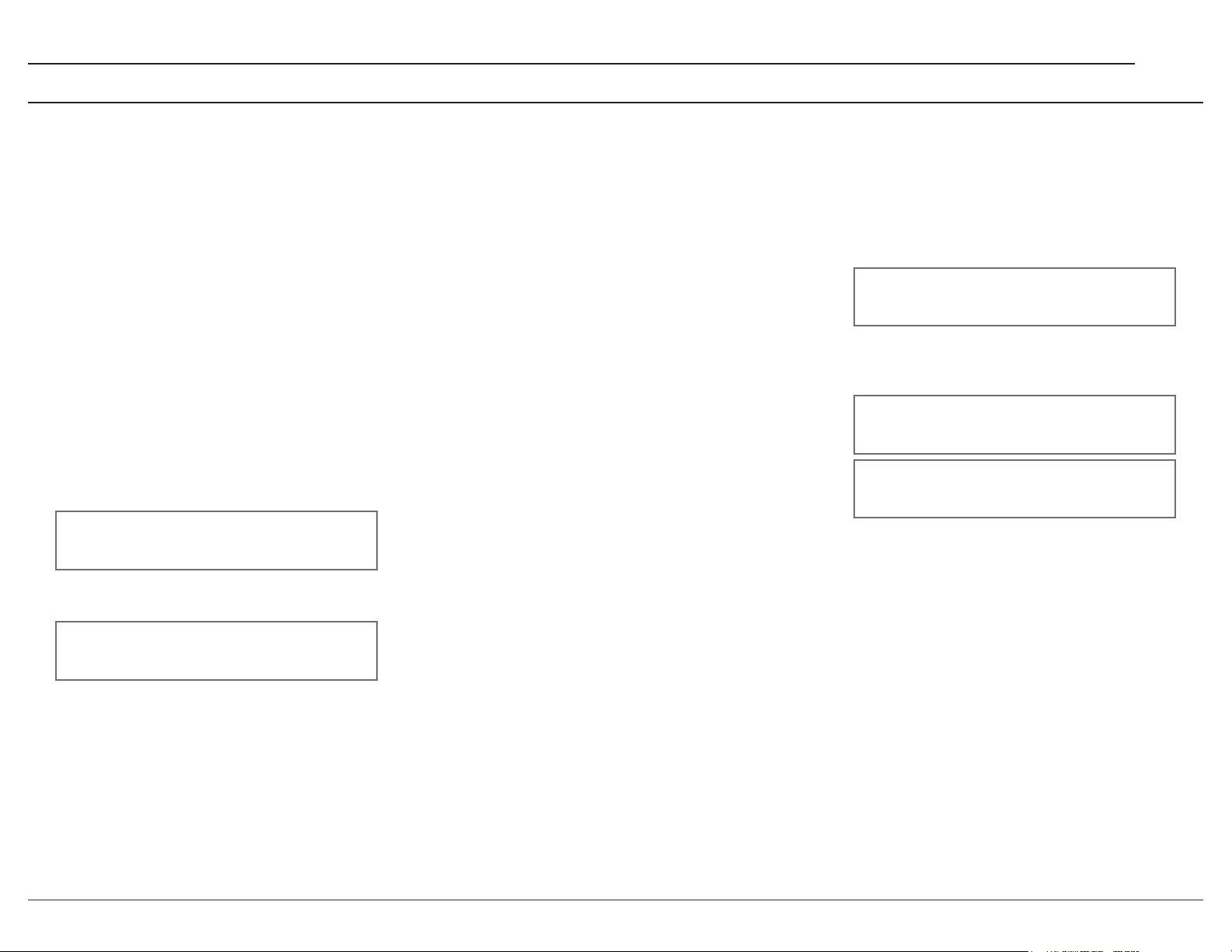
System: < Passthru >
Off >
Auto Off
The C55 incorporates an Auto Off feature, which
automatically places the Preamplier into the
Standby/Off Mode. This occurs approximately 30
minutes after there has been an absence of user
activity (includes changes to any of the Operation
Functions such as source selection, volume adjust
ment, etc.) or absence of an audio signal. This
feature is turned on by default but can be disabled
in the System Setup Menu.
Power Save
Disabled: The network connection will remain
active during standby. May also reduce wake up
time.
Enabled: The network connection will be lost in
standby. The unit can be turned on by IR remote
control, power control, RS232, or by pressing the
front panel STANDBY/ON Button.
Restore Defaults
To reset all the adjustable settings (Setup and Trim
Settings) to the factory default values, perform the
following steps:
1. Select the Defaults option in the System
Setup Menu. The following should be on the
-
Information Display.
System: < Defaults >
Hold INPUT to Reset
3. Press and hold in the INPUT Knob until the
following appears on the Information Display,
then release the INPUT Knob.
System: < Defaults >
In Progress!
System: < Defaults >
Completed!
4. Press the front panel STANDBY/ON Button to
switch the C55 on.
3. Rotate the VOLUME Knob to select “BAL 2”
Input.
System: < Passthru >
< BAL 2 >
4. Exit the System Setup Menu by pressing the
INPUT Knob.
Factory Reset
To reset all adjustable settings and clear all network
information, select Factory Reset and follow the
same process as above.
11
Page 12
Digital Setup Menu
Settings Options
DA Firmware Version
DA Update
OPT 1 Gain 0dB to +15dB in 1dB intervals
OPT 2 Gain 0dB to +15dB in 1dB intervals
HDMI Gain 0dB to +15dB in 1dB intervals
HDMI Lip Synchronize Mode Manual, Automatic
HDMI CEC Power Disabled, Enabled
HDMI CEC Volume Disabled, Enabled
DA Firmware Version
The C55 functionality is controlled by internal
software that is know as Firmware. The Firmware
Number for the Digital Audio Circuitry of the C55,
and can be viewed by following the steps below:
1. Press and hold the INPUT Knob to enter the
Setup Menu.
2. Rotate the INPUT Knob until the Front Panel
Information Display indicates
SETUP: Menu Select
< Digital >
3. Press and hold the INPUT Knob to open the
Digital Setup Menu and the Information Display
will show the DA Firmware version.
DA Update
This option is for service purposes only.
Digital Gain
The C55 offers Digital Gain Adjustments for the
HDMI, OPTICAL 1 (OPT 1) and OPTICAL 2
(OPT 2) Inputs. The change in gain of a specic
Digital Input, will produce a change in playback
volume of the music. To change the gain for the
HDMI Input perform the following steps:
1. Use the INPUT Knob to enter the Digital Setup
Menu.
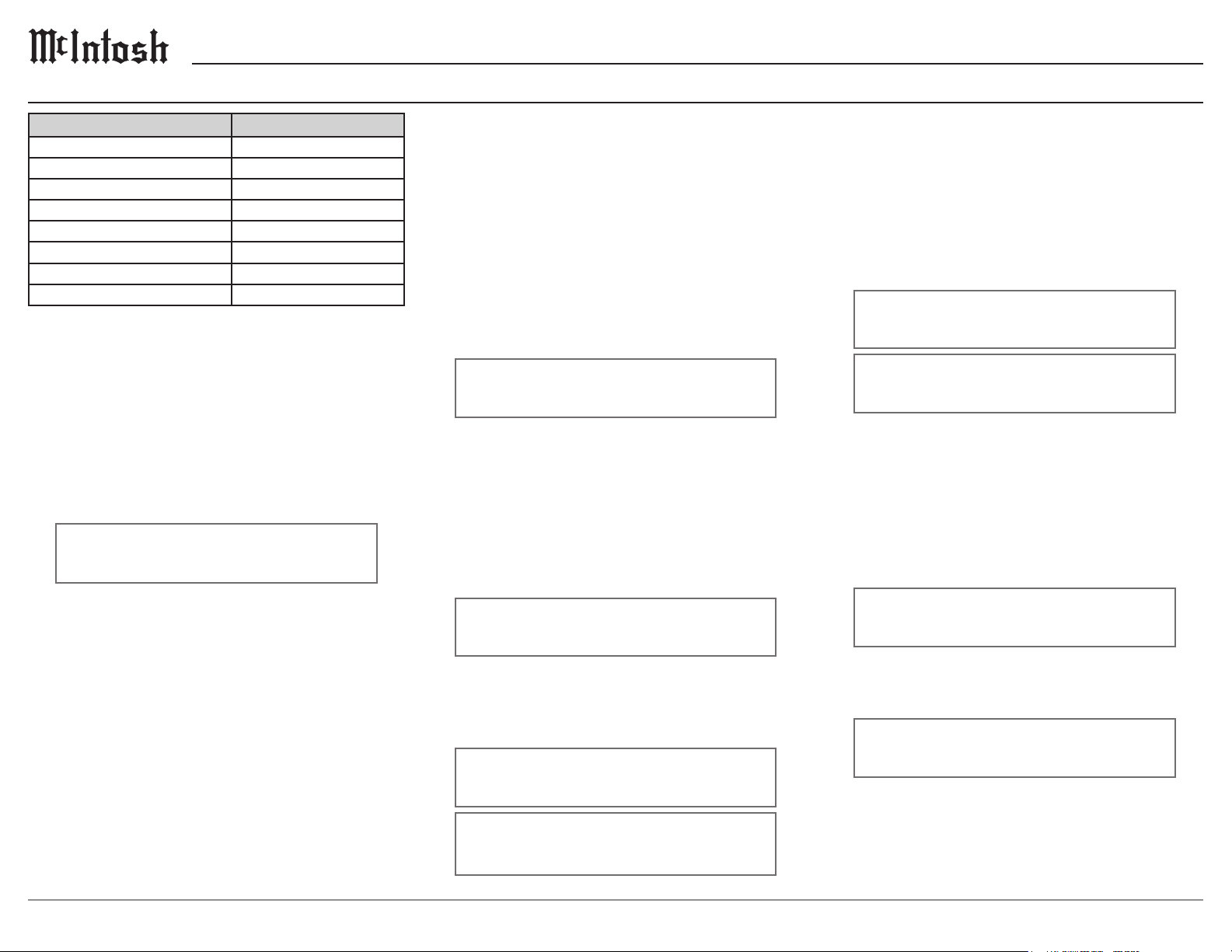
2. Rotate the INPUT Knob until the following
appears on the Information Display.
Digital: < HDMI (ARC) >
+15dB
3. The gain can be adjusted in 1dB Gain steps by
rotating the VOLUME Knob counterclockwise
to reduce the gain downwards from +15 dB all
the way to 0dB.
4. To adjust other Gain values, rotate the INPUT
Knob to select OPT 1 or OPT 2 and the gain is
adjustable in 1dB Gain steps. 0 dB is the default
setting for Optical 1 and Optical 2.
Digital: < OPT 1 >
0 dB
5. The gain can be increased by rotating
VOLUME Knob clockwise to increase the gain
from 0 dB with an increase all the way up to
+15 dB or +8dB from 0 dB.
Digital: < OPT 1 >
+ 15 dB
HDMI (ARC) CEC Power
The C55 HDMI Input Connector has (ARC) Audio
Return Channel Circuitry, allowing the Audio
Selection and Control Command of HDMI TV/
Monitor Devices. By default the HDMI Input is
congured to accept Power commands via CEC.
To prevent the CEC Power Control of the C55,
simply change HDMI CEC Power from On to Off.
Digital: < CEC Power >
< Enabled
Digital: CEC Power
Disabled >
HDMI (ARC) CEC Volume
To change the Consumer Electronics Control
(CEC) of the volume, perform the following steps:
1. Use the INPUT Knob to enter the Digital Setup
Menu.
2. Rotate the INPUT Knob until the following
appears on the Information Display.
Digital: < CEC Volume
< Enabled
3. To deactivate the Consumer Electronics Control
(CEC), rotate the VOLUME Knob until the
following appears on the Information Display.
Digital: < CEC Volume
Disabled >
12
Digital: < OPT 2 >
+ 8 dB
Page 13
Digital Setup Menu (continued)
C55
Inputs Setup Menu
HDMI (ARC) Lip Sync Mode
The C55 HDMI Input Connector (ARC), also
has another control function. When listening and
viewing a TV/Monitor HDMI Input Signal, the
ARC circuitry provides a synchronized Video
and Audio TV/Monitor Signal. To switch Off the
AUTO Synchronised Video and Audio TV/Monitor
Signal, perform the following steps:
1. Use the INPUT Knob to enter the Digital Setup
Menu.
2. Rotate the INPUT Knob until the following
appears on the Information Display.
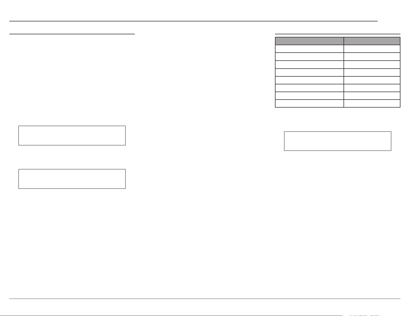
Digital: < Lip Sync >
< Auto
3. To manually congure the lip sync delay, rotate
the VOLUME Knob until the following appears
on the Information Display.
Digital: < Lip Sync >
Manual >
4. The delay time can then be adjusted from the
Trim Menu when the HDMI (ARC) Input is
selected.
Setting Options
BAL 1-3 On/Name, Off
UNBA L 1-4 On/Name, Off
PHONO 1, 2 On/Name, Off
COAX 1, 2 On/Name, Off
OPT 1, 2 On/Name, Off
USB On/Name, Off
MCT On/Name, Off
HDMI(A RC) On/Name, Off
Hold the INPUT Knob to open the Inputs Setup
Menu and from there, the following changes can be
made:
SETUP: Menu Select
< Inputs >
On/Name: The selected input will be functioning
as normal. Hold in the INPUT Knob to enter the
menu to rename the input*.
Off: The selected input will be deactivated and
will no longer be selectable from the main display
during normal use. Change this setting back to “On
/Name” to make it selectable again.
*Naming Inputs: While in the selected input’s
submenu, use the INPUT Knob to navigate to the
input with the name you’d like to change (and turn
it On using the VOLUME Knob if it isn’t already)
so that the display says “Inputs: [ input name ]
On/Name” and hold the INPUT Knob to begin
renaming. The character you are currently adjust
-
ing will be blinking. Rotate the INPUT Knob to
select which character you want to change and use
the VOLUME Knob to change the character.
13
Page 14
+6
Outputs Setup Menu
The Outputs Setup Menu provides the ability
to change how the C55 Output 1, Output 2 and
Headphones function.
Settings Options
Output Mode Switched, Unswitched,
Bi-Amped (Fixed),
Bi-Amped (Split)
Output Trim Level
(only Output 1)
Bi-Amp Center Frequency
-6.0dB to +3.0dB
in 0.5dB intervals
150Hz, 350Hz, 900Hz
(only Fixed Mode)
Bi-Amp High Pass
Frequency (only Split Mode)
Bi-Amp Low Pass
Bypass, 50Hz, 100Hz,
250Hz
600Hz, 1200Hz, 3000Hz
Frequency (only Split Mode)
Dual Mono (Output 2) Off, On
Headphones Mute All Outputs, Mute No
Outputs
Output Mode
The Outputs on the C55 can be independently
congured to operate in one of several modes.
• Switched (Default) - The Output is set to allow
toggling by using the Front Panel OUTPUT 1
and 2 Buttons, or by using the OUTPUT 1 and 2
Buttons on the Remote Control.
• Unswitched - The Output is set to On, and
toggling is disabled.
• Bi-Amped (Fixed) - This mode is a variant of
Unswitched that is exclusive to Output 1 and
enables the Bi-Amp Circuitry in Fixed Mode.
• Bi-Amped (Split) - This mode is the same as
Bi-Amped (Fixed) but Bi-Amp Circuitry is in
Split Mode.
Output Trim Level
Adjusts the level of Output 1 relative to the Main
Output. This setting is always active, and is useful
for bi-amping.
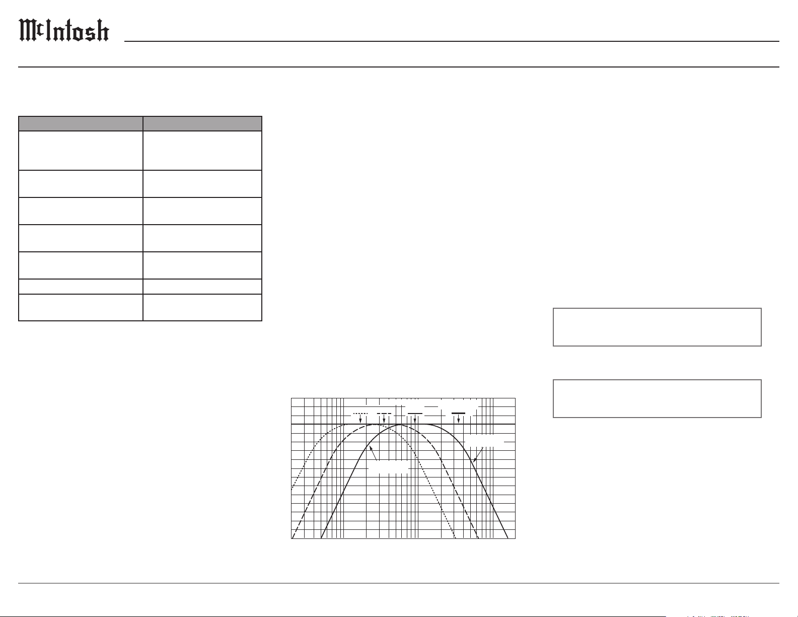
Bi-Amp Circuitry
The C55 has internal, adjustable crossover. The
C55’s crossover tailors the output frequency
range of each amplier section to the attached
loudspeaker. In Fixed Mode, simply set the
Center to the loudspeaker’s Crossover Point, then
frequencies above the Crossover Point will be
sent to the MAIN Output and frequencies below
the Crossover Point will be sent to Output 1. In
Split Mode, the lter’s corner frequencies can be
independently congured. As an example, the
High Pass Outputs could be sent to a vacuum tube
amplier, and the Low Pass Outputs could be sent
to a solid-state amplier. This adjustable crossover
allows you to optimize the performance of your
ampliers to your speaker’s specications and
to your listening preferences. A direct feed can
also be connected to each amplier section, thus
bypassing the internal crossover.
+4
+2
0
-2
-4
-6
-8
-10
Decibels
-12
-14
-16
-18
-20
-22
-24
-26
20 30 50 100 200 300 500 1k 2k 3k 5k 10k 20k
CROS SOVER P OINTS
150Hz 350 Hz
High Pass Response
(Lo w Cut)
900Hz
Frequency (Hz)
Combined Response
(Fu ll R ange)
Low Pass Response
(Hi gh Cut)
Dual Mono
Output 2 can be congured as either a stereo
or mono output. These connections can feed an
additional full range amplier and speaker system,
or can feed a single mono subwoofer or 2 separate
Left/Right (stereo) subwoofers.
Headphones
The C55 Default Setting for using Headphones is to
automatically mute all the Output Connectors when
the Headphone Cable Plug is inserted into the C55
Front Panel HEADPHONES Jack. There are two
available settings:
Mute All Outputs
Mute No Outputs
1. Rotate the INPUT Knob until the following
appears on the Information Display.
Outputs: < HEADPHONES
Mute All Outputs >
2. Rotate the VOLUME Knob to change the
current HEADPHONES setting.
Outputs: < HEADPHONES
< Mute No Outputs
3. Exit the Outputs Setup Menu by pressing the
INPUT Knob.
14
Page 15
Triggers Setup Menu Data Out Setup Menu
C55
The C55 has four Power Control Triggers
Connections. When the C55 Is On, the Triggers are
either activated or deactivated. Trigger 1, 2, 3 and
4 settings can be assigned to one of the available
Outputs, or any combination of Inputs. These
settings will control the operational power to the
components connected to the various C55 Trigger
Output Connectors. Perform the following steps to
setup the Trigger:
1. Use the INPUT Knob to enter the Data Out
Setup Menu.
2. Rotate the INPUT Knob until the following
appears on the Information Display.
SETUP: Menu Select
< Triggers >
3. Press and hold in the INPUT Knob to select the
Triggers Menu.
4. Rotate the INPUT Knob to select between
TRIGGER 1, TRIGGER 2, TRIGGER 3, or
TRIGGER 4.
5. Rotate the VOLUME Knob to change the
selected Trigger’s assignment.
6. If “Input” is selected as in the image to follow,
the Trigger will be congured according to
the Inputs that are enable in the corresponding
submenu.
Triggers: TRIG 1 >
< Input (Hold INPUT)
7. To change the Trigger’s Input conguration,
press and hold in the INPUT Knob.
8. Rotate the INPUT Knob to navigate the set of
Inputs.
9. Rotate the VOLUME Knob to enable / disable
the selected Input as in the following image.
Triggers: TRIG 1 >
< BAL 1 > : Off
10. Repeat steps 4-9 to congure any of the other
Triggers.
11. Exit the Triggers Setup Menu by pressing the
INPUT Knob a couple times.
Data Port Connections between the C55 and a
McIntosh Source Component allow for basic
function control of the source component using
the C55 supplied HR085 Remote Control. By
default, all of the four Data Ports are set to send
the same Data to the selected source. To dedicate
a given Data Port for only one source component
(example, source component connected to the BAL
1 Input will be assigned to Data Port 1) perform the
following Steps:
1. Use the INPUT Knob to enter the Data Out
Setup Menu.
2. Rotate the INPUT Knob until the following
appears on the Information Display.
SETUP: Menu Select
< Data Out >
3. Press and hold in the INPUT Knob until the
following appears on the Display.
Data Out: PORT 1 >
All Data >
4. Rotate the VOLUME Knob to select “BAL 1”
Input.
Data Out: PORT 1 >
< BAL 1 >
5. In a similar manner, perform steps 3 and 4 to
assign any additional Data Ports.
6. Exit the Data Out Setup Menu by pressing the
INPUT Knob.
15
Page 16
External Control Setup Menu
Settings Options
Front I R Enabled, Disabled
RS232 Baud Rate 115200 Baud
IR Codes Normal, Alternate
IR Codes
The Remote Control included with the C55 utilizes
the NORMAL McIntosh Control Codes. The
Second Set of Control Codes the C55 will respond
to is referred to as the ALTERNATE Codes. The
Alternate Codes are used when the C55 is used in
the same location as another McIntosh Preamplier
and/or A/V Processor. This will prevent the
Remote Control from affecting the operation of
both units at the same time. To activate the Remote
Control ALTERNATE Codes perform the follow
ing steps:
1. Use the INPUT Knob to enter the External
Control Setup Menu.
2. Rotate the INPUT Knob until the following
appears on the Information Display.
-
Front IR
The C55 Front Panel Sensor, which receives the
signals from the HR085 Remote Control, can
be switched off to prevent interference when an
external IR Sensor is connected. To de-activate the
Front Panel IR Sensor perform the following steps:
1. Use the INPUT Knob to enter the External
Control Setup Menu.
2. Rotate the INPUT Knob until the following
appears on the Information Display.
Ext Ctrl: Front IR >
< Enabled
3. Rotate the VOLUME Knob to select “Disabled”.
Ext Ctrl: Front IR >
Disabled >
4. Exit the External Control Setup Menu by
pressing the INPUT Knob.
RS232 Baud Rate
The C55 may be remotely controlled from other
equipment connected to the Rear Panel RS232
Jack. The speed at which the C55 communicates
(8 bit, no parity and 1 stop bit) with other equipment is adjustable from 9,600 bits per second to
115,200 bits per second. To change from the default
speed of 115,200 bits per second, perform the
following steps:
1. Use the INPUT Knob to enter the External
Control Setup Menu.
2. Rotate the INPUT Knob until the following
appears on the Information Display.
Ext Ctrl: < RS232 >
< 115200 Baud
3. Rotate the VOLUME Knob to select the desired
Baud Rate Speed.
4. Exit the External Control Setup Menu by
pressing the INPUT Knob.
Ext Ctrl: < IR Codes
< Normal
3. Rotate the VOLUME Knob to the Alternate
Codes.
Ext Ctrl: < IR Codes
Alternate >
4. It is now necessary to change the HR085
Remote Control over to the Alternate Codes.
Information on the HR085 Remote Control
is available for download from the McIntosh
website.
5. Exit the External Control Setup Menu by
pressing the INPUT Knob.
16
Page 17
System Conguration
C55
Connecting Components
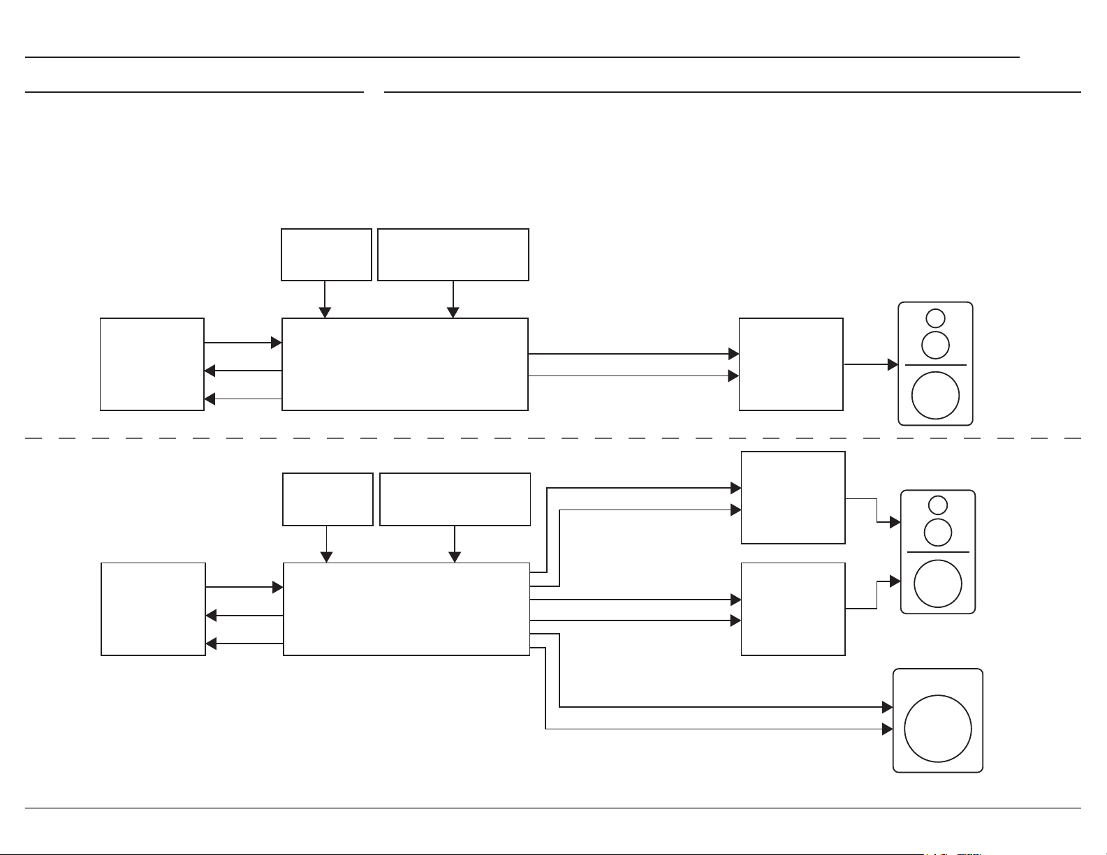
Shown below are two typical system congurations. Your system may vary from this, however
the actual components would be connected in a
similar manner.
Note: The preamplifier or power amplifier may be connected to
the C55 balanced or unbalanced outputs.
Example 1
Example 2
AUDIO
SOU RCES
ANALOG OR
DIGI TAL
AUDIO
POW ER
CONTROL
DATA
IR
REMOTE
CON T ROL
IR
REMOTE
CON T ROL
The C55 has the ability to automatically switch power On/Off to Source Components via the Power
Control connections. The Data Port Connections allow for the remote operation of basic functions using
the C55 Remote Control HR085. With an external sensor connected to the C55, remote control operation
of the system is possible from another room and/or when the C55 is located in a cabinet with the doors
closed.
RS232 / NETWORK
CONTROL SYSTEM
SPEAKER
C55 AU DIO
PREAMPLIFIER
RS232 / NETWORK
CONTROL SYSTEM
MAIN
VAR IA BLE ANALOG AUDIO
POW ER CON TROL
VAR IA BLE ANALOG AUDIO
POW ER CON TROL
POW ER
AMP
FULL R ANGE)
(
POW ER
AMP
(HIGH PA S S)
SPEAKER
AUDIO
SOU RCES
ANALOG OR
DIGI TAL
AUDIO
POW ER
CONTROL
DATA
C55 AU DIO
PREAMPLIFIER
MAIN
OUT 1
OUT 2
VAR IA BLE ANALOG AUDIO
POW ER CON TROL
VAR IA BLE ANALOG AUDIO
POW ER CON TROL
POW ER
AMP
LOW PASS)
(
POWERED
SUBWOOFER
(OPTIONAL)
17
Page 18
Trim Functions MenuNetwork Information Menu
The Network Information Menu lists information
about network connection. Press the VOLUME
Knob to open the Network Information Menu.
Navigate between settings using the INPUT Knob.
The chart below details all of the available settings.
Settings Options
Connection Type Displays Connection Type
IP Address Displays IP Address
Ethernet MAC Address Displays Ethernet MAC Address
Wi-Fi MAC Address Displays Wi-Fi MAC Address
McIntosh Connect App
Press and hold the VOLUME Knob to put the C55
into Network Setup Mode. The NETwork Status
LED will blink–indicating that network settings
can be congured from the McIntosh Connect
App.
Note: The C55 will exit Network Setup Mode if put into Standby.
The Trim Settings are stored in memory indepen
dently for each Input Source Selected, except the
Meter Illumination and Display Brightness settings
of On or Off, which are the same for all inputs.
How to Select and Adjust Trim Functions
1. Press the Front Panel INPUT Knob to open the
Trim Menu.
2. Rotate it to select the desired Trim Function.
3. Rotate the VOLUME Knob to change the
setting.
Note: the Remote Control TRIM Button together with the LEVEL
UP / LEVEL DN Button may also be used to access and
change Trim Functions.
Approximately 5 seconds after making any
changes, the Information Display will return to
indicate the Source Selection and Volume Level.
Trim Functions Menu Options
Settings Options
Balance L, Center, R
Input Trim -6dB to +6dB in 1dB intervals
Equalizer Mode On, Off
Mono/Stereo Mode Stereo, Mono
Processor Loop On, Off
Meter Lights On, Off
Brightness 4 Levels
Dim Bright
Phono Capacitance 50pF to 400pF in 50pF
increments
Phono Resistance
Phono Gain 40dB to 64dB in 6dB intervals
Lip Sync Delay 0 to 150ms in 10ms intervals
HXD Mode* On, Off
Note: HXD Mode will only appear if headphones are plugged in.
25, 50, 100, 200, 400, 1k, 47k Ω
Balance
Listening balance varies with different program
sources, room acoustics and listening positions
relative to the loudspeakers. Use the Balance (Trim
Function) as needed to achieve approximately
equal listening volume levels in each loudspeaker.
The Front Panel Display indicates the Balance
changes are from 0 to 50 dB. After approximately
4 seconds the Information Display returns to
indicate the Source Selection and Volume Level. To
verify the Balance setting without changing it, use
the TRIM Button and select Balance.
Input Trim Level
Source Components can have slightly different
volume levels resulting in the need to readjust the
C55 VOLUME Knob when switching between
different sources. The C55 allows the adjustment
of levels for each of the Source Inputs for the same
relative volume.
Mono/Stereo Mode
By default, the Stereo Mode is active for all
Input Sources however, any Input Source may
be assigned to the Mono Mode of operation. To
change Stereo Mode to Mono for a given Input
Source, perform the same type of steps by using
the Front Panel Controls or the Remote Control
Pushbuttons as done for EQUALIZER Settings:
Note: The audio signal present at the SEND FIXED OUT Jacks is
affected by the Stereo/Mono setting.
Processor Loop
Connects or disconnects an external equalizer or
room correction processor.
18
Page 19
2k 5k 10k 20k
Trim Functions Menu (continued) Equalizer Controls
C55
Meter Illumination
The Meter Illumination of McIntosh Power
Ampliers, when connected to the C55, may be
switched On or Off. If using non-McIntosh compo
nents see page 21.
Information Display Illumination
The brightness level of the Front Panel Information
Display can be adjusted. It has 4 levels that vary
from dim to bright.
Phono Adjustments
First select the Phono 1 or Phono 2 Input then
press and rotate the INPUT Knob to display the
active type of load setting for the phono cartridge
selected.
Phono Capacitance
Rotate the INPUT Knob to select desired
Capacitance.
The available settings are: 50pF, 100pF, 150pF,
200pF, 250pF, 300pF, 350pF, and 400pF.
Phono Resistance
Rotate the INPUT Knob to select desired
Resistance.
The available settings are: 25Ω, 50Ω, 100Ω, 200Ω,
400Ω, 1KΩ, and 47kΩ.
Lip Sync Delay
When the Lip Sync Mode is set to Manual, and
when the HDMI Input is selected, the Trim menu
will allow the HDMI Audio Lip Sync Delay to be
adjusted from 0 to 150mS in 10mS intervals.
HXD Mode
When headphones are connected to the C55 Front
Panel Jack, an additional TRIM function becomes
available. McIntosh’s HXD brings the acoustical
depth and spatiality of music normally heard with
loudspeakers, to your headphones.
Note: The Headphone Output is optimized for impedances
ranging from 100 to 600 ohms.
Equalizer Mode
The built-in eight band Frequency Equalizer
provides more precise adjustment of sound than
standard Bass and Treble Controls. By default,
the Equalizer is Off for all Input Sources and the
Equalizer Circuitry is bypassed. Any Input Source
may be assigned to have the Equalizer On when
selected.
Note: The audio signal present at the SEND FIXED OUT Jacks is
unaffected by the Equalizer settings.
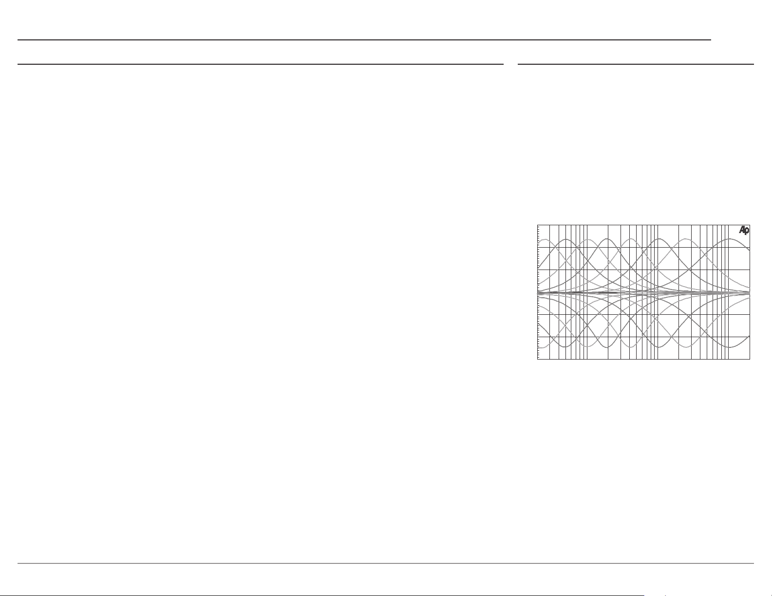
The C55 Equalizer has eight Frequency Controls
which will raise or lower by 12 dB, the amplitude
of the band of frequencies centered at the
frequency marked above the controls. The center
frequencies of these controls are at 25Hz, 50Hz,
100Hz, 200Hz, 400Hz, 1,000Hz, 2,500Hz and
10,000Hz. Both Left and Right Channels are
affected. At the center detent or at position of the
controls, the tone circuit components are removed
from the signal path.
Note. The audio signal present at the SEND FIXED OUT Jacks is
unaffected by the Equalizer Circuitry.
+15
A
+10
M
P
L
I
T
+ 5
U
D
E
I
0
N
D
E
- 5
C
I
B
E
L
-10
S
-15
20 50 100 200 500 1k
FREQUENCY IN HERTZ
Phono Gain
Rotate the INPUT Knob to select desired Gain.
The available settings are 40db, 46db, 52db, 58db,
and 64db.
19
Page 20
How to Operate the C55
Power On and Off
The Red LED above the STANDBY/ON Button
lights to indicate the C55 is in Standby mode.
To switch ON the C55, press the STANDBY/
ON Button on the Front Panel or the (Power
- Green) Button on the Remote Control. The C55
will go through a brief startup initialization with
the Front Panel Information Display indicating
the last used source and volume setting. This is
followed by the volume setting indication starting
at zero and then increasing to the last used volume
setting.
BAL 1 15%
To switch OFF the C55 press the STANDBY/ON
Button on the Front Panel or the (Power - Red)
OFF Button on the Remote Control.
Note: For an explanation of the Remote Control Button functions,
refer to page 8.
Source Selection
Rotate the INPUT Knob to select the desired
source or press the INPUT Upp or Downq
Button on the Remote Control.
PHONO 2 37%
50pF 200Ω
VOLUME Knob
Rotate the Front Panel VOLUME Knob or use the
VOLUME Upp or Downq Buttons on the Remote
Control for the desired listening level.
Mute
Press the MUTE Button, on the C55 Front Panel
or on the Remote Control, to Mute the Audio
in all outputs (Main, Output 1, Output 2 and
Headphones) except the SEND FIXED OUT. The
Front Panel Information Display will indicate the
Source Name and the word MUTE in place of the
actual volume setting.
BAL 1 MUTE
Pressing the Mute Button a second time or adjust-
ing the VOLUME Knob (either the Front Panel or
Remote Control) will unmute the C55.
Output 1 and 2
Press the Front Panel OUTPUT 1 or OUTPUT 2
Button or use the Remote Control and press the
SETUP/BLUE Button followed by the OUTPUT
1 or OUTPUT 2 Button, to send audio to separate
Power Ampliers connected to the rear panel
OUTPUT 1 or 2 Jacks. It also activates the
POWER CONTROL TRIGger 1 or 2 Jacks on the
rear panel of the C55. To stop the Audio and Power
Control Signals from going to the separate Power
Ampliers, press the same Button(s) a second time.
Passthru
Refer to Passthru Information in the C55 Setup
Section on page 14 to activate the function and
select the desired Input on the C55.
The C55 will automatically turn On and switch
to the previously setup Passthru Input when the
McIntosh A/V Processor or Multichannel Surround
Decoder is turned-on. The Audio Preamplier
Front Panel Alphanumeric Display will indicate
“Pas sth r u”.
The C55 OUTPUT 1 and 2 are active when in the
Passthru Mode. The other Front Panel Controls
and Buttons are deactivated as long as the Passthru
Mode is active.
Headphone Jack
Connect a pair of dynamic headphones to the
Headphones Jack with a 1/4” (0.635cm) stereo
phone type plug for private listening. The default
setting is for all of the Power Amplier Output
Connections (1 and 2) to automatically mute.
How To Make a Recording
1. Select the desired signal source you wish to
record by using the Front Panel INPUT Knob
or using the INPUT UP / DOWN Button on the
Remote Control.
2. Adjust the record level using the recorder level
control and proceed with the recording process.
3. Listen to the playback of the program source
just recorded by selecting the Input Source
connected to the recorder component output.
20
Page 21
How to Operate the C55 (continued)
C55
Troubleshooting
Digital Inputs
When a Digital Input on the C55 is selected,
the Front Panel Information Display indicates
the sample rate or audio format when a signal is
present.
During the time there is no Digital Signal present
the display will indicate “______”.
MCT Input
When playing a multi-layer SACD, select the stereo
(SACD) or CD layer. The multi-channel layer will
not reproduce sound.
Optical
The two Optical Inputs allow digital sources to
be connected to the C55 using TOSLINK cables
also known as “optical audio cables.” The optical
inputs can handle high resolution digital audio
up to 192kHz/24-bit. The C55 DAC will process
standard format S/PDIF PCM signals and Dolby
Digital and DTS bitstreams. Unsupported formats
can result in strange and/or unpleasant sounds.
Coaxial
The two Digital Coaxial Inputs allow digital
sources to be connected to the C55 using Digital
Audio RCA Coaxial cables. The COAX inputs
can handle high-resolution digital audio up
to 192kHz/24-bit. The C55 DAC will process
standard format S/PDIF PCM signals and Dolby
Digital and DTS bitstreams. Remember, unsup
ported formats can result in strange and/or unpleasant sounds.
HDMI ARC
The HDMI ARC (Audio Return Channel) allows
you to use your entire audio system to play the
sound from your TV.
Notes:• Ensure you are connected to the TV’s HDMI input
port that is labeled “ARC”.
•
Your TV’s setup menu and settings may need to be
adjusted before sound is heard.
•
When the C55 is set to the HDMI input, the
unit will automatically turn On and Off with the TV.
The front display will show “Entering HDMI
Standby Mode” when turning Off.
•
Multi-channel formats will be down mixed to a
2-channel output.
Audio formats supported by HDMI ARC:
• PCM (2 channel)
• Dolby Digital (up to 5.1 channel)
• DTS Digital Surround (up to 5.1 channel)
USB Audio
The USB Audio Input of the C55 provides the
capability to receive music/sound in a digital
format from a connected computer.
Software Requirements
®
Apple
communicate with the C55 without any installa
tions necessary.
For Windows-based computers (PC), Windows 7
(Service Pack 1) or later is required. The correct
McIntosh USB Audio driver must be installed for
the PC to communicate with the C55.
To install the McIntosh USB driver for Windowsbased computers download the latest driver from
the McIntosh website.
The driver can be found in the Downloads section
of the webpage under Software Updates. Choose
the DA2 Digital Audio Module: McIntosh USB
Audio Windows Driver. You may select this driver
in many third-party applications such as JRiver
Media Center.
The C55’s display will show the sampling rate or
bit rate for the USB Audio Input.
computers with OS-10.6.8 are able to
-
Reset of Microprocessors
In the unlikely event the controls of the C55 stop
functioning, the microprocessors can be reset by
performing the following:
1. Press and hold in the STANDBY/ON Button
until the LED above the STANDBY/ON Button
illumination is extinguished. Then release the
STANDBY/ON Button.
2. To switch the C55 back On, press the
STANDBY/ON Button.
Note: This can be performed with the C55 On or in the Standby
Mode.
Meter Lights
Meter lights in Power Amps and Source units have
the ability to be turned On and Off by the C55.
But sometimes if a non-McIntosh unit is used, the
Meter lighting circuit is defeated and the lights are
always Off.
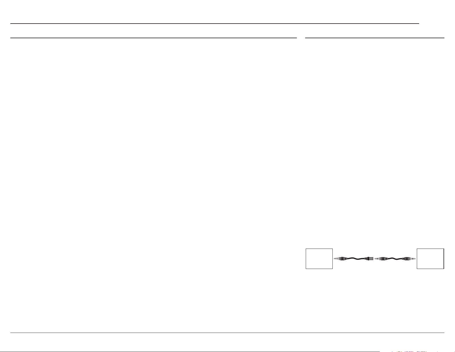
To remedy this, place a 173419 Trigger Adapter
Cable in-line with the normal 170202 Power
Control cable.
This Adapter leaves the ring terminal uncon
nected, which allows the meter lights to remain
illuminated.
Non-McIntosh
Product
TRIGGER OUT
System Connection Example
173419 170202
M – F
Adapter Cable
M – M
Stereo Cable
-
McIntosh
Product
POWER CONTROL IN
TRIGGER IN
PASS THRU IN
21
Page 22

Specications
Note: all measurements with EQ filters and output filters bypassed.
Frequency Response
+0, -0.5dB from 20Hz to 20,000Hz
+0, -3dB from 15Hz to 100,000Hz
Total Harmonic Distortion
0.005% from 20Hz to 20,000Hz
Rated Output
2.5V Unbalanced, 5V Balanced (Main)
450mV (Fixed Output)
Maximum Voltage Output
8V RMS Unbalanced, 16V RMS Balanced
Sensitivity (for rated output)
High Level, 450mV Unbalanced, 900mV Balanced
Phono MM, 4.5mV
Phono MC, 0.45mV
Signal To Noise Ratio (A-Weighted)
High Level - 100dB (Below rated output)
MM Phono - 82dB (Below 5mV input)
MC Phono - 80dB (Below 0.5mV input)
Input Impedance
High Level 22K ohms Unbalanced
44k ohms Balanced
Phono 1, 2 (MM and MC)
25, 50, 100, 200, 400, 1k or 47k ohms
50 to 400pF in 50pF steps
Maximum Input Signal
High Level, 5V Unbalanced, 10V Balanced
Phono MM, 80mV
Phono MC, 8mV
Equalizer Controls
25Hz, 50Hz, 100Hz, 200Hz, 400Hz, 1,000Hz,
2,500Hz and 10,000Hz
Voltage Gain
High Level to Fixed Output: 0dB
High Level to Main Output: 15dB
Phono 1, 2 (MM and MC) Selectable 40dB, 46dB,
52dB, 58dB, or 64dB
Output Impedance
100 ohms Unbalanced
200 ohms Balanced
Headphone Load Impedance
100 ohms to 600 ohms
Digital Input Sample Rates
Coaxial: PCM -16Bit, 24Bit - 44.1kHz to 192kHz
Optical: PCM - 16Bit, 24Bit - 44.1kHz to 192kHz
USB: PCM - 16Bit, 24Bit, 32Bit - 44.1kHz to
384kHz
MCT: PCM, SACD, -16Bit, 24Bit - 44.1kHz to
192kHz
DXD - DXD352.8kHz, DXD384kHz
DSD - DSD64, DSD128, DSD256, DSD512
HDMI: PCM 24bit, 44.1kHz - 192kHz
DTS
Dolby Digital
Power Control and Trigger Output
12VDC, 25mA
Power Requirements
Field AC Voltage conversion of the C55 is not
possible. The C55 is factory congured for one of
the following AC Voltages:
100 Volts, 50/60Hz at 75 watts
110 Volts, 50/60Hz at 75 watts
120 Volts, 50/60Hz at 75 watts
220 Volts, 50/60Hz at 75 watts
230 Volts, 50/60Hz at 75 watts
240 Volts, 50/60Hz at 75 watts
Standby Power, less than 0.5 watts
Note: Refer to the rear panel of the C55 for the correct voltage.
Overall Dimensions
Width is 17 1/2 inches (44.4cm)
Height is 7 5/8 inches (19.4cm) including feet
Depth is 18 inches (45.72cm) including the Front
Panel, Knobs and Cables
Weight
28 pounds (12.5 kg) net, 43.5 pounds (19.7 kg) in
shipping carton
Shipping Carton Dimensions
Width is 27 inches (68.6cm)
Height is 12 inches (30.5cm)
Depth is 25 inches (63.5cm)
Trademarks of McIntosh Laboratory, Inc.:
The following are Registered Trademarks of McIntosh Laboratory, Inc. in multiple jurisdictions around the world: the written McIntosh
logo; the McIntosh Globe logo; the Mc logo; Power Guard; Power Guard Screen Grid Sensor; Power Guard SGS; Sentry Monitor; LD/HP;
Dynamic Power Manager; the 4DPM8 logo; HXD; the HDX logo; Behind The Sound; Legendary Performance.
The following are Trademarks of McIntosh Laboratory, Inc. in multiple jurisdictions around the world: Autoformer; Solid Cinch; McIntosh
Monogrammed Heatsinks; Hybrid Drive; DualView; TripleView; Made of Sound.
The foregoing trademarks, registered and otherwise, are not to be used, reproduced, or registered in any way without the express written
permission of McIntosh Laboratory, Inc.
22
Page 23
Packing Instructions Parts List
C55
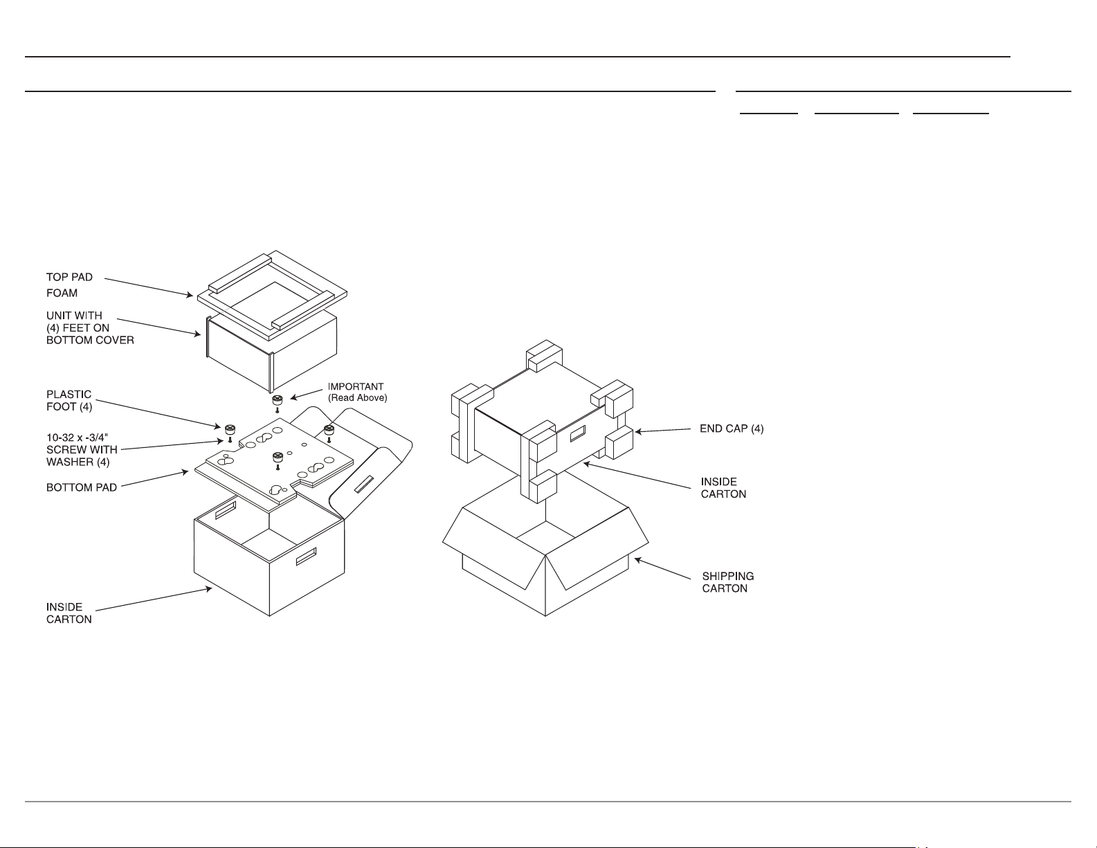
In the event it is necessary to repack the equipment for shipment, the equipment must be packed
exactly as shown below. It is very important that
the four plastic feet are attached to the bottom
of the equipment. This will ensure the proper
equipment location on the bottom pad. Failure
to do this will result in shipping damage.
( )
Use the original shipping carton and interior parts
only if they are all in good serviceable condition.
If a shipping carton or any of the interior part(s)
are needed, please call or write Customer Service
Department of McIntosh Laboratory. Refer to
page 2. Please see the Part List for the correct part
numbers.
Quantity Part Number Description
1 033888 Shipping carton only
4 034670 End cap
1 033697 Inside carton only
1 034414 Top pad (foam)
1 034576 Bottom pad
4 017937 Plastic foot
4 400159 #10-32 x 3/4” screw
4 404080 #10-7/16” Flat washer
23
Page 24

McIntosh Laboratory, Inc.
2 Chambers Street
Binghamton, NY 13903
www.mcintoshlabs.com
The continuous improvement of its products is the policy of McIntosh Laboratory Incorporated
who reserve the right to improve design without notice. The C55 is designed to employ
non-McIntosh-provided services some of which require separate customer subscriptions and
some of which do not, as part of the Product’s functionality. Because McIntosh cannot control
the providers of such services or the services themselves, the owner of the Product therefore
assumes all risks related to the use of services provided by anyone other than McIntosh itself.
McIntosh cannot and does not warrant against, and shall have no liability of any kind for any
of the following that are attributable to non- McIntosh providers or services: (i) interruption,
discontinuance, or other unsatisfactory performance of service; (ii) reduced Product function-
ality that is so attributable; or (iii) any other loss or damage of any kind that is so attributable.
Printed in the U.S.A.
© 2023 McIntosh Laboratory, Inc.
McIntosh Part No. 24124000
 Loading...