

Page 1
McIntosh Laboratory, Inc. 2 Chambers Street Binghamton, New York 13903-2699 Phone: 607-723-3512 www.mcintoshlabs.com
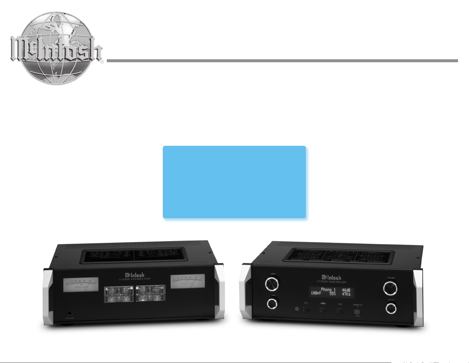
C12000
&
C12000
Owner’s Manual
Controller
Preamplifier
Page 2
The lightning ash with arrowhead, within an equilateral triangle,
ATTENTION:
RISQUE DE CHOC ELECTRIQUE - NE PAS OUVRIR
is intended to alert the user to the presence of uninsulated “dangerous voltage” within the product’s enclosure that may be of sufcient magnitude to constitute a risk of electric shock to persons.
The exclamation point within an equilateral triangle is intended to
alert the user to the presence of important operating and maintenance (servicing) instructions in the literature accompanying the
appliance.
WARNING - TO REDUCE RISK OF FIRE OR
ELECTRICAL SHOCK, DO NOT EXPOSE
THIS EQUIPMENT TO RAIN OR MOISTURE.
IMPORTANT SAFETY
INSTRUCTIONS!
PLEASE READ THEM
BEFORE OPERATING THIS EQUIPMENT.
1. Read these instructions.
2. Keep these instructions.
3. Heed all warnings.
4. Follow all instructions.
5. Do not use this apparatus near water.
6. Clean only with a dry cloth.
7. Do not block any ventilation openings. Install in accordance
with the manufacturer’s instructions.
8. Do not install near any heat sources such as radiators, heat
registers, stoves, or other apparatus (including ampliers)
that produce heat.
9. Do not defeat the safety purpose of the polarized or grounding-type plug. A polarized plug has two blades with one
wider than the other. A grounding type plug has two
blades and a third grounding prong. The wide blade or the
third prong are provided for your safety. If the provided
plug does not t into your outlet, consult an electrician for
replacement of the obsolete outlet.
10. Protect the power cord from being walked on or pinched
particularly at plugs, convenience receptacles, and the
point where they exit from the apparatus.
11. Only use attachments/accessories specied by the manufacturer.
12. Use only with the cart, stand, tripod, bracket,
or table specied by the manufacturer, or sold
with the apparatus. When a cart is used, use
caution when moving the cart/apparatus combination to avoid injury from tip-over.
13. Unplug this apparatus during lightning storms or when
unused for long periods of time.
NO USER-SERVICEABLE PARTS INSIDE.
REFER SERVICING
TO QUALIFIED PERSONNEL.
14.
Refer all servicing to qualied service personnel. Servicing
is required when the apparatus has been damaged in any
way, such as power-supply cord or plug is damaged, liquid
has been spilled or objects have fallen into the apparatus,
the apparatus has been exposed to rain or moisture, does
not operate normally, or has been dropped.
15. Do not expose this equipment to dripping or splashing and
ensure that no objects lled with liquids, such as vases,
are placed on the equipment.
Ne pas exposer cet appareil à des éclaboussures ou
gouttelettes d’un liquide. Aucun objet remplie de liquide comme par exemple un vase ne doit être placé sur
l’appareil.
16. If this equipment is supplied with a power supply cord
only, the mains plug of the power supply cord shall remain
readily operable. To completely disconnect this equipment
from the a.c. mains remove the plug from the a.c. receptacle.
Si l’équipement est uniquement alimenté par un cordon
d’alimentation, la che du cordon d’alimentation doit demeurer aisément accessible. Pour déconnecter complètement l’équipement du réseau d’alimentation, déconnecter
la che du cordon d’alimentation de la prise murale.
17. If this equipment is supplied with AC /DC Adapter with
separate power supply cord or the AC/DC Adapter plugging directly into an a.c. receptacle, they shall remain
readily operable. To completely disconnect this equipment
from the a.c. mains remove the AC /DC Adapter mains
power supply cord from the a.c. receptacle or remove the
AC /DC Adapter when it is directly plugged into the a.c.
receptacle.
Si l’équipement est alimenté par un adaptateur AC/DC
munis d’un cordon d’alimentation ou un adaptateur AC/
DC qui est alimenté directement à la prise murale, ils
doivent demeurer aisément accessibles. Pour déconnecter
complètement l’équipement du réseau d’alimentation,
déconnecter l’adaptateur AC/DC de la prise murale ou
To prevent the risk of electric shock,
do not remove cover or back. No
user-serviceable parts inside.
déconnecter le cordon d’alimentation de l’adaptateur AC/
DC de la prise murale.
18. WA R N I N G : Do not expose batteries or battery pack to
excessive heat such as sunshine, re or the like.
AVERTISSEMENT: Les batteries ou bloc de batteries ne doivent pas etre exposees a une chaleur excessive
telle que celle du soleil, feu ou autre source de chaleur
similaire.
19. CAUTION: danger of explosion if battery is incorrectly
replaced. Replace only with the same or equivalent type.
ATTENTION: danger d’explosion si la pile n’est pas
remplacée correctement. Ne remplacer que par le même
type ou un type équivalent.
20. Connect mains power supply cord only to a mains socket
outlet with a protective earthing connection.
21. WA R N IN G : The Ethernet connector of this equipment
must not be directly connected to a public network. Connection is to be made only by way of a modem or router
approved for this purpose.
WARNING
The McIntosh C12000 is a two chassis design,
with separate Preamplifier and Controller chassis.
There are custom interconnecting cables
and custom chassis sockets used
to connect the two chassis together.
Use ONLY the custom interconnect cables supplied
with the C12000 to connect the chassis together.
Do NOT connect the C12000 Left and Right
25-Pin Chassis Sockets to any other component.
Failure to observe this warning
will result in damage to the components connected.
2
Page 3

Thank You from all of us at McIntosh
Table of Contents
You have invested in a precision instrument that
will provide you with many years of enjoyment.
Please take a few moments to familiarize yourself
with the features and instructions to get the
maximum performance from your equipment.
If you need further technical assistance, please
contact your dealer who may be more familiar with
your particular setup including other brands. You
can also contact McIntosh with additional questions
or in the unlikely event of needing service.
McIntosh Laboratory, Inc.
2 Chambers Street
Binghamton, New York 13903
Technical Assistance (607) 723-3512
Fax (607) 724-0549
Customer Service (607) 723-3515
Fax (607) 723-1917
Email [email protected]
Website www.mcintoshlabs.com
Please Take A Moment
For future reference, you can write down your serial
number and purchase information here. We can
identify your purchase from this information if the
occasion should arise:
Serial Number: ______________________________
Purchase Date: ______________________________
General Information ........................................4
Connector and Cable Information ...................4
Introduction ...................................................... 5
Performance Features .......................................5
Dimensions - C12000 Controller ......................6
Installation - C12000 Controller .......................7
Dimensions - C12000 Preamplifier ..................8
Installation - C12000 Preamplifier ...................9
Navigating the Rear Panel (Controller) ...........10
Navigating the Rear Panel (Preamp) ...............11
Connecting Components .................................12
Input Assignment Chart .................................. 13
Navigating the Remote Control ......................14
Front Panels ..................................................... 15
Controller Connection Diagram ..................... 16
Preamplifier Connection Diagram..................18
How to Operate the Setup Mode ....................20
Fi r m wa re Ve rsion ............................................20
Input Settings ..................................................20
Output Settings ...............................................22
Headphone Settings .......................................22
Power Control Triggers ...................................22
Data Ports ........................................................23
Passthru ...........................................................23
Comm Port Baud Rate ....................................24
Remote Control Codes ....................................24
IR Sensor ........................................................24
Power Mode ....................................................24
Factory Reset .................................................25
How to Operate the C12000 ...........................25
Specifications .................................................30
Packing Instructions ...................................... 31
Dealer Name: ______________________________
Copyright © 2021 by McIntosh Laboratory, Inc.
3
Page 4
PIN 3
General Information
Ground
1.
The C12000 System consists of two separate chassis;
a “Controller” and a “Preamplifier”. When specific
clarification is necessary for instruction, the separate
chassis will be referenced individually with their
corresponding names. Otherwise, “C12000” will be
used to reference the unit as a whole.
2. For additional connection information, refer to the
owner’s manual(s) for any component(s) connected to
the C12000 Audio Preamplifier.
3. The Main AC Power going to the C12000 and
any other McIntosh Component(s) should not
be applied until all the system components are
connected together. Failure to do so could result in
malfunctioning of some or all of the system’s normal
operations. When the C12000 and other McIntosh
Components are in their Standby Power Off Mode, the
Microprocessor’s Circuitry inside each component is
active and communication is occurring between them.
4. Balanced and Unbalanced Inputs and Outputs can be
mixed. For example, you may connect signal sources
to Unbalanced Inputs and send signals from the
Balanced Outputs. You can also use Balanced and
Unbalanced Outputs simultaneously, connected to
different Power Amplifiers.
5. Sound Intensity is measured in units called Decibels
and “dB” is the abbreviation.
6. The McIntosh C12000 is factory configured for
immediate use. It can also be customized to complement the components making up your system. Refer
to the C12000 “Setup Mode” starting on Page 20 for
additional information.
7. The Remote Control Supplied with the C12000
is capable of operating other components. For
additional information go to
www.mcintoshlabs.com.
8. The IR Input, with a 3.5mm mini phone jack, is
configured for non-McIntosh IR sensors such as
a Xantech Model HL85BK Kit. Use a Connection
Block such as a Xantech Model ZC21 when two
or more IR sensors need to be connected to the
C12000. The signal from a connected External IR
Sensor will have priority over the signal from the
Front Panel IR Sensor.
9. Controller to Preamplier Cable Part No. 171872 is
three foot, shielded 23 conductor, male-to-female
custom cable. Two cables are required between
Controller and Preamplier.
Do not use any other cable when connecting the
C12000 Controller to the C12000 Preamplier.
10. When discarding the unit, comply with
local rules or regulations. Batteries
should never be thrown away or incinerated but disposed of in accordance
with the local regulations concerning
battery disposal.
11. For additional information on the C12000 and
other McIntosh Products please visit the McIntosh
Web Site at www.mcintoshlabs.com.
Connector and Cable Information
XLR Connectors
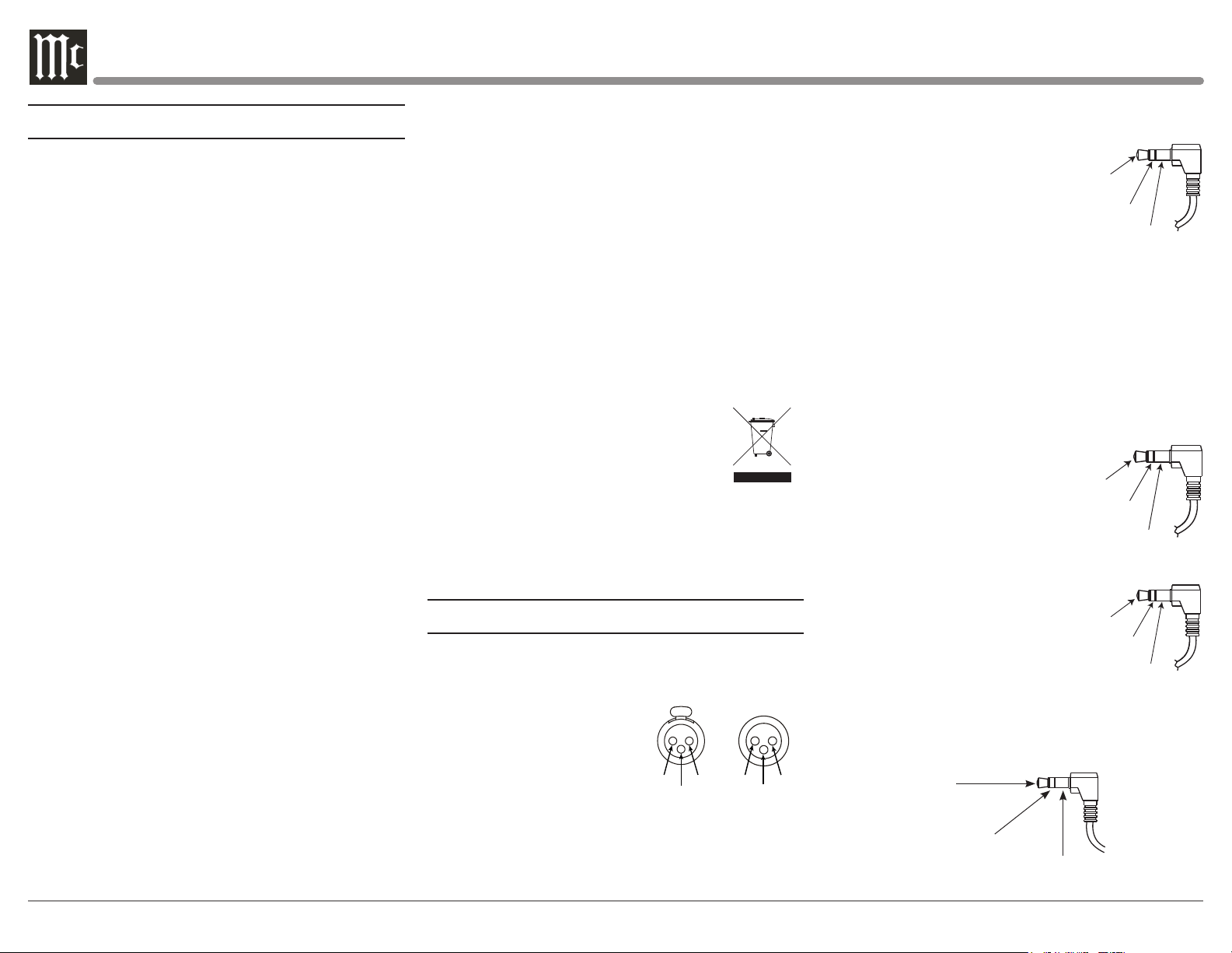
Below is the Pin configuration for the XLR Balanced
Input and Output Connectors on the C12000. Refer to
the diagrams for connections:
PIN 1: Shield/Ground
PIN 2: + Output
PIN 3: - Output
PIN 2 PIN 1
PIN 1
Power Control and Trigger Connectors
The C12000 Power Control Out, Trigger and
PASSTHRU Output Jacks send Power On/Off Signals
(+12 volt/0 volt) when connected to other McIntosh
PIN 3
PIN 2
Components. An additional connection is for controlling the illumination of the Power Output Meters on
McIntosh Power Amplifiers.
A 3.5mm stereo mini phone plug
is used for connection to the Power
Main, Triggers 1-4
and PASSTHRU
Power
Control
Meter
Illumination
Control
Ground
Control, Trigger and PASSTHRU
Outputs on the C12000.
Note: The Power Control, Trigger, PASSTHRU and Data
Connecting Cable is available from the McIntosh
Parts Department:
Power Control, Trigger, PASSTHRU and Data
Cable Part No. 170202
Six foot, shielded 2 conductor, with 3.5mm stereo
mini phone plugs on each end.
Data Port Connectors
The C12000 Data Out Ports
send Remote Control Signals to
Source Components. A 3.5mm
stereo mini phone plug is used
Data
Signal
N/C
Data
Ground
for connection.
IR IN Port Connectors
The IR IN Port also uses a 3.5mm
stereo mini phone plug and allows
IR Data
Control
N/C
the connection of other brand IR
Receivers to the C12000.
RS232 Port Connector
The RS232 Port uses a 3.5mm stereo mini phone plug
to connect to external third-party controllers.
Tip: C12000 TXD Out
Data Being Transmitted from C12000
Ring: C12000 RXD In
Data Being Received by C12000
Ground
4
Page 5

Introduction
The McIntosh C12000 Preamplifier is one of the
finest ever created. The Outputs have the ability to
drive multiple Power Amplifiers with the versatility of
choosing between any combination of Solid State and
Tube amplification. The C12000 Audio Reproduction
is sonically transparent and absolutely accurate. The
McIntosh Sound is “The Sound of the Music Itself.”
Performance Features
Dual Chassis with Dual Mono Design - The Dual
Chassis design completely separates all power supply,
microprocessor and control circuits from the pure
audio circuits for total noise isolation. To further aid
in channel isolation, the circuitry for both channels is
totally separate, physically isolated and shielded; and
incorporates two identical power supplies one for each
channel, to help assure total channel isolation.
Vacuum Tube Phono Amplification - The C12000
utilizes Vacuum Tube Amplification Circuitry for
the Phono Inputs. The circuits use the latest designs
providing the lowest possible noise and distortion.
Selectable High-Level Amplification - The C12000
has the Output 1 and Output 2 ports dedicated to Solid
State Amplification and Tube Amplification respectively. Combined with the ability to assign the Main
Output to either use Solid State or Tube via the Trim
Menu (refer to Page 29), the C12000 is equipped to
deliver high perfromance in any environment for any
preference.
Fully Balanced Circuitry - The C12000 utilizes the
very latest in Fully Balanced Circuitry from the Input
Connectors all the way to the Output Connectors for
the lowest possible noise and distortion.
Phono Inputs - The C12000 has two precision
Phono Preamplifier Circuits. They have the ability
to be configured for Moving Coil or Moving
Magnet Cartridges. The close tolerance resistors and
capacitors used in the RIAA Correction Equalization
Circuitry provide an extremely flat frequency
response.
Selectable Phono Cartridge Loading - Adjustable
Capacitance and Resistance Loading are available
for both Moving Coil and Moving Magnet Phono
Cartridges. Resistance Loading is selectable from
values of 25 ohms to 47,000 ohms. Capacitance
Loading is selectable from values of 50 picofarads to
400 picofarads.
Adjustable Gain for Phono Inputs - The C12000’s
Phono Inputs have a wide range of gain settings to
accommodate a variety of Phono Cartridges.
Illuminated Output Meters - The Illuminated
Output Meters are peak responding, and indicate the
output of the C12000 Phono Preamplifier.
Electromagnetic Input Switching with Level Trim
Adjustment - Digital Logic integrated circuits drive
Electromagnetic Switches on all Inputs and operating
functions for reliable, noiseless, distortion free switching. All the Inputs on the C12000 can be matched in
level, so there are no abrupt changes in volume levels
between the different Inputs.
Balanced Inputs - The Balanced Inputs allow the
connection of a source component using long cable
lengths without a loss in sound quality.
Precision Tracking Volume Control - Volume levels
are controlled by a Precision Balanced Digitally
Controlled Attenuator System with an Optical
Encoder Rotary Control. This assures a 0.1dB tracking
accuracy between channels. There are 214 individual
0.5dB volume level steps with no noise as the volume
level is changed.
Variable Rate Volume and Balance Controls - The
C12000’s Volume and Balance Control Circuitry
provides an ideal rate of change with control rotation.
HXD® for Headphones - The C12000 Headphone
Crossfeed Director Circuitry (HXD® ) improves the
sound localization for Headphone Listening. HXD
®
restores the directionality component of the spatial
sound stage normally heard with Loudspeaker listening. HXD® is a registered trademark of McIntosh
Laboratory, Inc.
Alphanumeric Fluorescent Display - The Front
Panel Information Display indicates the Source
Selection, Volume/Balance Levels and Setup Mode
Selections. The display intensity is adjustable.
PASSTHRU Mode - The Automatic PASSTHRU
Mode allows the C12000 to become part of a Home
Theater Multichannel Sound System.
Remote Control with External Sensor Input - The
Remote Control provides control of the C12000
operating functions and McIntosh Source Components
connected to it. Enjoy your McIntosh System from
another room in your home by connecting an external
sensor.
Power Control Output and Trigger Assignment - A
Power Control connection for convenient Turn-On of
McIntosh Power Amplifiers, Source Components and
Accessories is included. The Power Control Trigger
Ouputs may be assigned to activate when a given
Input/Output is selected.
Dual Special Power Supply - Two fully separate and
regulated Power Supplies with special R-Core Power
Transformers ensure stable noise free operation even
though the power line varies.
LED Front Panel Illumination - The even
Illumination of the Front Panel is accomplished by
multiple extra long life Light Emitting Diodes (LEDs)
arranged with a special orientation.
Glass Front Panel and Super Mirror Chassis
Finish - The famous McIntosh Illuminated Glass
Front Panel and the Lower Chassis are Stainless Steel
with a Mirror Finish. The Upper Chassis and Top
Cover is hairline brushed black Titanium Stainless
Steel Finish. This will ensure the pristine beauty of
the C12000 will be retained for many years to come.
5
Page 6
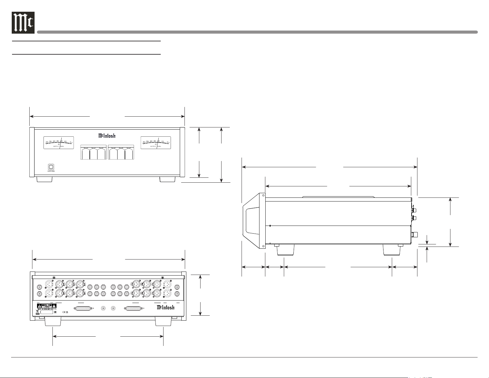
Dimensions - C12000 Controller
15-1/8”
10-9/16”
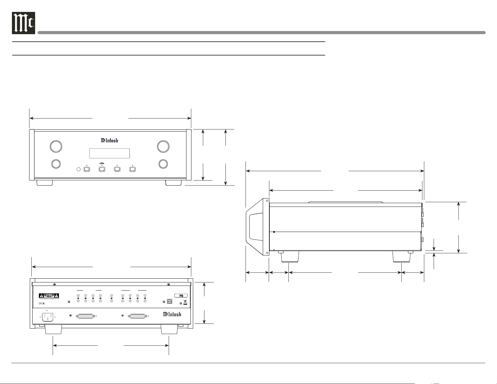
The following dimensions can assist in determining the best location for your C12000 Controller.
There is additional information on the next page pertaining to installing the C12000 Controller into cabinets.
Front View of the C12000 Controller
17-1/2”
44.5cm
INPUT
TRIM
MENU
SETUP
C1 2 0 0 0 CON T R OL L ER
Balanced 1
70%
MUTE
STANDBY / ON
RESET
Rear View of the C12000 Controller
17”
43.2cm
CAUTION
RISK OF ELECTRIC SHOCK
DO NOT OPEN
120V 50/60Hz
75 WATTS
POWER CONTROL
TRIG 3TRIG 1
OUT 1
OUT 2
TRIG 4TRIG 2 RS232
RIGHT OUTPUT
TO C12000 PREAMPLIFIER
RIGHT INPUT
MAIN
PASSTHRU
1
2
DATA PORTSEXTERNAL CONTROL
3
4
TO C12000 PREAMPLIFIER
5
6
LEFT OUTPUT
LEFT INPUT
7IR IN
8
VOLUME
ADJUST
SERIAL
UPDATE
NUMBER
USB
C12 00 0 CON TR OLL ER
McINTOSH LABORATORY, INC. BINGHAMTON, NY 13903
HANDCRAFTED IN USA WITH US AND IMPORTED PARTS
5-3/8”
13.7c m6”15.2cm
4-5/8”
11. 8 c m
2-1/4”
5. 7cm
Side View of the C12000 Controller
17-3/8”
44.1c m
38.4cm
26.8cm
2”
5.1c m
2-9 /16”
6.5cm
3/16”
0.5cm
4-7/8”
12.4cm
6
13-1/4”
33. 7cm
Page 7
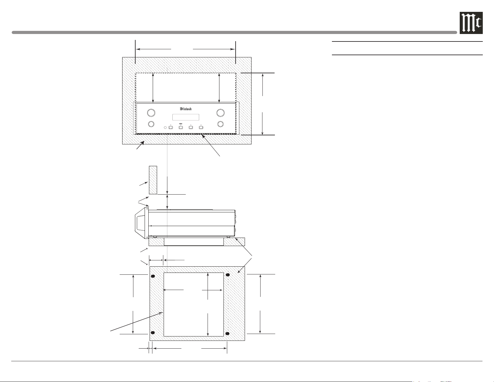
C12000 Controller
Front Panel
Custom Cabinet Cutout
Cabinet Front Panel
Opening
for Ventilation
C12000 Controller
Side View
in Custom Cabinet
C12000 Controller
Bottom View
in Custom Cabinet
Note: Center the cutout Horizontally
on the unit. For purposes of clarity,
the above illustration is not drawn to scale.
Cabinet
Front
Panel
Support
Shelf
15-1/16"
38.3cm
1-1/8"
2.9cm
17-3/16"
43.66cm
Opening for Ventilation
INPUT
TRIM
MENU
SETUP
C1 2 0 0 0 CO N TR O LL E R
Balanced 1
70%
6"
15.2cm
8-1/8"
23.2cm
Cutout
Opening
for
Ventilation
12-5/16"
31.3cm
VOLUME
MUTE
STANDBY / ON
Cutout Opening for Custom Mounting
Cutout Opening
for Ventilation
7/8"
2-
7.3cm
ADJUST
RESET
13-1/8"
33.3cm
27.3cm
Chassis
Spacers
15-1/16"
39.6cm
10-3/4"
Installation - C12000 Controller
The C12000 Controller can be placed upright on a
table or shelf, standing on its four feet. It also can be
custom installed in a piece of furniture or cabinet
of your choice. The four feet may be removed from
the bottom of the unit when it is custom installed as
outlined below. The four feet together with the mounting screws should be retained for possible future use
if the C12000 Controller is removed from the custom
installation and used free standing. The required panel
cutout, ventilation cutout and unit dimensions are
shown.
Always provide adequate ventilation for your
C12000 Controller. Cool operation ensures the longest
possible operating life for any electronic instrument.
Do not install the Controller directly above a heat
generating component such as a high powered amplifier. Also do not stack the C12000 Preamplifier on top
of the C12000 Controller. If all the components are
installed in a single cabinet, a quiet running ventilation fan can be a definite asset in maintaining all the
system components at the coolest possible operating
temperature.
A custom cabinet installation should provide the
following minimum spacing dimensions for cool
operation.
Allow at least 6 inches (15.2cm) above the top, 2
inches (5.1cm) below the bottom and 1 inch (2.5cm)
on each side of the Controller, so that airf low is not
obstructed. Allow 20 inches (50.8cm) depth behind the
front panel. Allow 1-7/16 inch (3.7cm) in front of the
mounting panel for knob clearance. Be sure to cut out
a ventilation hole in the mounting shelf according to
the dimensions in the drawing.
7
Page 8
15-1/8”
10-9/16”
Dimensions - C12000 Preamplier
The following dimensions can assist in determining the best location for your C12000 Preamplifier.
There is additional information on the next page pertaining to installing the C12000 Preamplifier into cabinets.
Front View of the C12000 Preamplifier
17-1/2”
44.5cm
C 1 2 0 0 0 P R E A M P L I F IE R
Rear View of the C12000 Preamplifier
17”
43.2cm
PUS H
MAIN
REC/FIXED
RIGHT OUTPUTS
CAUT IO N
RISK O F E LE CT R IC S HO CK
DO NOT O PE N
ATTENTION: RISQUE DE CHOC ELECTRIQUE-NE PAS OUVRIR
SERIAL
NUMBER
PU
S
H
1-SS
1
PUS
H
2-T
2
RIGHT BALANCED INPUTS RIGHT UNBALANCED INPUTS
3
P
US
H
4
RIGHT INPUT
TO C12000 CONTROLLER
RIGHT OUTPUT
P
U
SH
5
PUS H
6
1
3
2 4 PH2
PH1
GND GND
PH1
3
LEFT UNBALANCED INPUTS
1
24PH2
LEFT INPUT
TO C12000 CONTROLLER
LEFT OUTPUT
PUS H
PUS H
5
PUS H PU S H
PUS H
PUS H
436
LEFT BALANCED INPUTS LEFT OUTPUTS
C 12 0 00 P R E AM P L I F I E R
McINTOSH LABORA TORY, INC. BINGHAMT ON, NY 13903
HANDCRAFTED IN USA WITH US AND IMPOR TED PAR TS
5-3/8”
Side View of the C12000 Preamplifier
13.7c m6”15.2cm
17-3/8”
44.1c m
38.4cm
4-7/8”
3/16”
0.5cm
2-1/4”
MAIN
1-SS
1
2-T
2
4-5/8”
REC/FIXED
11. 8 c m
5. 7cm
2”
5.1c m
26.8cm
2-9 /16”
6.5cm
12.4cm
8
13-1/4”
33. 7cm
Page 9
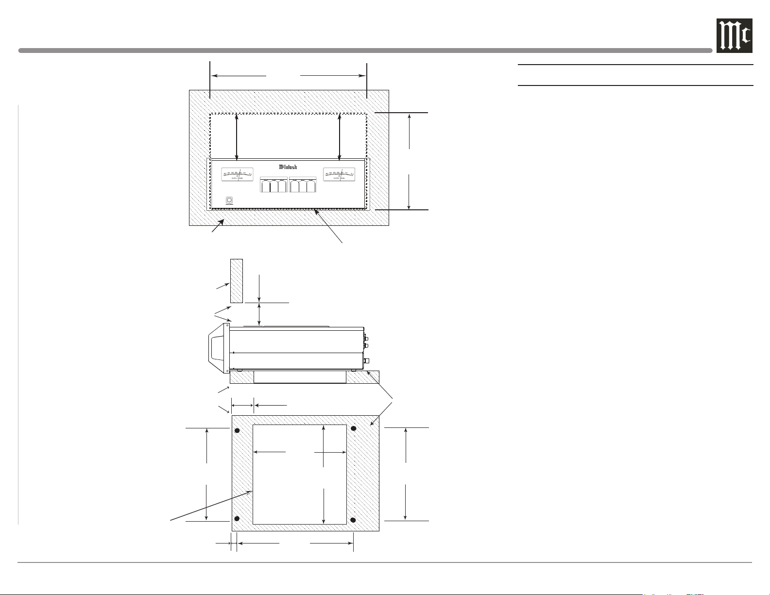
C12000 Preamplifier
Front Panel
Custom Cabinet Cutout
C12000 Preamplifier
Side View
in Custom Cabinet
Cabinet Front Panel
Cabinet
Front
Panel
Opening
for Ventilation
Support
Shelf
17-3/16"
43.66cm
Opening for Ventilation
C1 20 0 0 PR E A M PL I F I E R
Cutout Opening for Custom Mounting
6"
15.2cm
Cutout Opening
for Ventilation
2-7/8"
7.3cm
10-3/4"
27.3cm
Chassis
Spacers
Installation - C12000 Preamplier
The C12000 Preamplifier can be placed upright on
a table or shelf, standing on its four feet. It also can
be custom installed in a piece of furniture or cabinet
of your choice. The four feet may be removed from
the bottom of the unit when it is custom installed as
outlined below. The four feet together with the mounting screws should be retained for possible future use if
the C12000 Preamplifier is removed from the custom
installation and used free standing. The required panel
cutout, ventilation cutout and unit dimensions are
shown.
Always provide adequate ventilation for your
C12000 Preamplifier. Cool operation ensures the
longest possible operating life for any electronic
instrument. Do not install the C12000 Preamplifier
directly above a heat generating component such as a
high powered amplifier. Also do not stack the C12000
Controller on top of the C12000 Preamplifier. If all
the components are installed in a single cabinet, a
quiet running ventilation fan can be a definite asset in
maintaining all the system components at the coolest
possible operating temperature.
A custom cabinet installation should provide the
following minimum spacing dimensions for cool
operation.
C12000 Preamplifier
Bottom View
in Custom Cabinet
Note: Center the cutout Horizontally
on the unit. For purposes of clarity,
the above illustration is not drawn to scale.
15-1/16"
38.3cm
1-1/8"
2.9cm
8-1/8"
23.2cm
Cutout
Opening
for
Ventilation
12-5/16"
31.3cm
13-1/8"
33.3cm
15-5/8"
39.6cm
Allow at least 6 inches (15.2 cm) above the top, 2
inches (5.1cm) below the bottom and 1 inch (2.5cm)
on each side of the Preamplifier, so that airf low is not
obstructed. Allow 20 inches (50.8cm) depth behind the
front panel. Allow 1-7/16 inch (3.7cm) in front of the
mounting panel for knob clearance. Be sure to cut out
a ventilation hole in the mounting shelf according to
the dimensions in the drawing.
9
Page 10
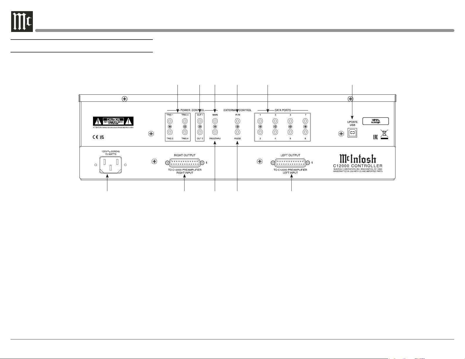
Navigating the Rear Panel (Controller)
7CR 8CR 9CR 10CR 11CR
1CR 2CR 3CR 4CR 5CR 6CR
1CR POWER CONTROL TRIGger outputs 1 thru 4 are
assignable to send turn On/Off signals to components
2CR POWER CONTROL OUT 1 and 2 send turn On/Off
signals to a McIntosh Component when Output 1 and
2 are activated
3CR POWER CONTROL MAIN Output sends turn On/Off
signals to a McIntosh Component when the C12000
Controller is switched On/Off
4CR IR INput for signals from a compatible IR Sensor for
Remote Control use
5CR DATA PORTS are assignable to send signals to
Source Components to allow control with the C12000
Controller Remote Control
10
6CR For Service Use Only
7CR Connect the C12000 Controller power cord to a live AC
outlet. Refer to information on the back panel of your
C12000 Controller to determine the correct voltage for
your unit
8CR RIGHT OUTPUT Connector accepts the custom
McIntosh 23-Conductor Cable. This cable
connects to the C12000 Controller RIGHT TUBE
PREAMPLIFIER INPUT. It supplies the control
signals and power supply voltages for the Right
Channel Circuitry in the Preamplifier
9CR PASSTHRU Power Control Input receives turn On/Off
signals from an Audio/Video Processor
10CR RS232 connector for connection to a computer or other
control device
11CR LEFT OUTPUT Connector accepts the custom
McIntosh 23-Conductor Cable. This cable connects to
the C12000 Controller LEFT TUBE PREAMPLIFIER
INPUT. It supplies the control signals and power
supply voltages for the Left Channel Circuitry in the
Preamplifier
Page 11
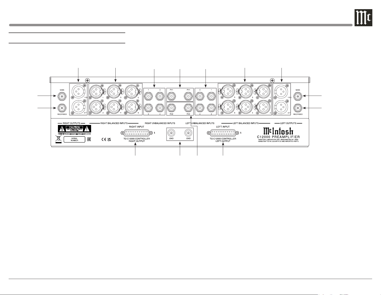
Navigating the Rear Panel (Preamp)
2PR 3PR
1PR
10PR
1PR
RIGHT OUTPUT MAIN (Unbalanced) sends signals
to a Power Amplifier - Can be configued to use Solid
State or Tube amplification (see Page 29)
2PR
RIGHT OUTPUT Balanced send signals to Power
Amplifier(s) and are switched On/Off using a trim
setting with the Front Panel Controls or Remote
Control Push-Buttons - Output 1 (1-SS) uses Solid
State amplification, Output 2 (2-T) uses Tube
Amplification
3PR
RIGHT BALANCED INPUTS 1 thru 6 accept high
level program source signals
4PR
RIGHT UNBALANCED INPUTS 1 thru 4 accept
high level program source signals
5PR
PH1 (Right and Left channels) accept signals from a
Phono Cartridge
4PR 5PR 6PR
11P R 12PR 13PR 14PR
6PR
LEFT UNBALANCED INPUTS 1 thru 4 accept high
level program source signals
7PR
LEFT BALANCED INPUTS 1 thru 6 accept high
level program source signals
8PR
LEFT OUTPUT Balanced send signals to Power
Amplifier(s) and are switched On/Off using a trim
setting with the Front Panel Controls or Remote
Control Push-Buttons - Output 1 (1-SS) uses Solid
State amplification, Output 2 (2-T) uses Tube
Amplification
9PR
LEFT OUTPUT MAIN (Unbalanced) sends signals
to a Power Amplifier - Can be configued to use Solid
State or Tube amplification (see Page 29)
10PR
RIGHT OUTPUT REC/FIXED sends signals to the
input of a recording device
7PR 8PR
11PR
RIGHT INPUT Connector accepts the custom McIntosh
23-Conductor Cable. This cable connects to the C12000
CONTROLLER OUTPUT. It supplies the control signals
and power supply voltages for the Right Channel Circuitry
in the Preamplifier
12PR
GND terminals accept a ground wire from a turntable
13PR
PH2 (Right and Left channels) accepts signals from a
Phono Cartridge
14PR
LEFT INPUT Connector accepts the custom McIntosh
23-Conductor Cable. This cable connects to the C12000
CONTROLLER OUTPUT. It supplies the control signals
and power supply voltages for the Left Channel Circuitry
in the Preamplifier
15PR
LEFT OUTPUT REC/FIXED sends signals to the
input of a recording device
9PR
15PR
11
Page 12
Connecting Components
The C12000 has the ability to automatically
switch power On/Off to Source Components via
the Power Control connections. The Data Port
Connections allow for the remote operation of
basic functions using the included HR085 Remote
Control. With an external sensor connected to the
C12000, remote control operation of the system
is possible from another room and/or when the
C12000 is located in a cabinet with the doors
closed.
The Connection Diagrams (Pages 16-19) are
examples of a typical audio system. Your system
may vary from this, however the actual components would be connected in a similar manner. For
additional information refer to “Connector and
Cable Information” on Page 4.
Note: The C12000 Controller allows re-naming of
the Audio Input Names as indicated on the
Front Panel Information Display. Example,
“UNBAL 1” may be changed to “TUNER”
or your own personal preference. Refer to
Input Settings on Page 20.
Power Control Connections:
1. Connect a Control Cable from the C12000
Controller POWER CONTROL MAIN Jack to
the Power Control In on the Turntable.
2. Connect a Control Cable from the Turntable
Power Control Out Jack to the Digital Audio
Player Trigger In Jack.
3. Connect a Control Cable from the Digital
Audio Player Trigger Out Jack to the SACD/
CD Player Power Control In Jack.
4. Connect a Control Cable from the SACD/CD
Player Power Control Out Jack to the AM/FM
Tuner In Jack.
5. Connect a Control Cable from the AM/FM
Tuner Power Control Out Jack to the Media
Bridge Pwr Ctrl (Power Control) In Jack.
6. Connect a Control Cable from the C12000
Controller POWER CONTROL OUT 1 Jack to
the Power Amplifier Power Control In Jack.
Notes: 1. If two separate Power Amplifiers are
used (Left and Right Channels), connect the
Power Control Output of the first Amplifier
to the Power Control Input on the second
Amplifier.
2. By the defaut settings, POWER
CONTROL OUT 1 and 2 are active by
default. They can be switched On/Off
by using the C12000 Controller TRIM
Function.
7. Optionally, connect a Control Cable from the
C12000 Controller POWER CONTROL OUT
2 Jack to the Power Amplifier (Secondary
Room) Power Control In Jack.
8. Connect any additional Components in a
similar manner, as outlined in steps 1 thru 5.
Data Control Connections:
9. Connect a Control Cable from the C12000
Controller DATA PORTS 2 Jack to the
TUNER Data In Jack.
Note: To have source components (e.g. Tuner)
respond only to their specific “Function
Commands” issued by the Remote Control,
it is first necessary change the Data Ports
Default settings for the “Tuner” Input. Refer
to Data Ports on Page 23.
10. Connect a Control Cable from the C12000
Controller CD DATA PORT 3 Jack to the
SACD/CD Player Data In Jack.
11. Connect a Control Cable from the C12000
Controller DATA PORT 1 Jack to the Media
Bridge Data In Jack.
12. Connect any additional McIntosh Components
in a similar manner, as outlined in steps 9 thru
11.
Sensor Connection:
13. Connect a Control Cable from the C12000
Controller IR INput Connector to the external
Sensor. For additional information, refer to
“General Information” note 8 on Page 4.
Audio Connections:
14. Connect an Audio Cable from the C12000
Preamplifier UNBALANCED INPUT 1
(Left and Right Channels) Jacks to the Tuner
Unbalanced Output Jacks.
15. Connect XLR Audio Cables from the C12000
Preamplifier BALANCED INPUT 1 (Left and
Right Channels) connectors to the SACD/CD
Player Balanced output connectors.
16. Connect XLR Audio Cables from the C12000
Preamplifier BALANCED INPUT 3 (Left
and Right Channels) connectors to the Media
Bridge Balanced output connectors.
17. Connect XLR Audio Cables from the C12000
Preamplifier BALANCED INPUT 2 (Left
and Right Channels) connectors to the Digital
Audio Player Balanced output connectors.
18. Connect the Audio Cables coming from the
Turntable to the C12000 Preamplifier PH1
or PH2 PHONO INPUT (Left and Right
Channels) Jacks.
19. Connect XLR Audio Cables from the C12000
12
Page 13
Preamplifier OUTPUT 1 connectors (Left
and Right Channels) to the Power Amplifiers
(Primary Room) Balanced (Left and Right)
Inputs.
20. Optionally, connect XLR Audio Cables from
the C12000 Preamplifier OUTPUT 2 connec-
tors (Left and Right Channels) to the Power
Amplifier (Secondary Room) Balanced (Left
and Right) Inputs.
21. Connect any additional McIntosh Components
in a similar manner, as outlined in steps 14
thr u 19.
Optional PASSTHRU Connections:
22. Connect XLR Audio Cables from the A/V
Processor, Front Channels (Left and Right)
Balanced Output connectors to the C12000
Preamplifier BALANCED INPUT 6 connec-
tors (Left and Right Channels).
Note: Refer to Passthru on Page 23 to activate the
BALANCED 6 Input.
23. Connect a Control Cable from the C12000
Controller PASSTHRU Jack to A/V Processor
Power Control Zone ZA Jack.
Ground Connections:
24. Connect the Ground Cable coming from the
Turntable to the C12000 Preamplifier PHONO
INPUT GND Binding Post.
C12000 Controller and Preamplifier
Inner Connections:
25. Connect one of the supplied custom cables
from the C12000 Controller RIGHT OUTPUT
Socket to the C12000 Preamplifier RIGHT
INPUT Socket. In a similar manner, connect
the second cable from the C12000 Controller
LEFT OUTPUT Socket to the C12000
Preamplifier LEFT INPUT Socket.
AC Power Cord Connections:
26. Connect the C12000 Controller to a live AC
Outlet using the supplied Power Supply Cord.
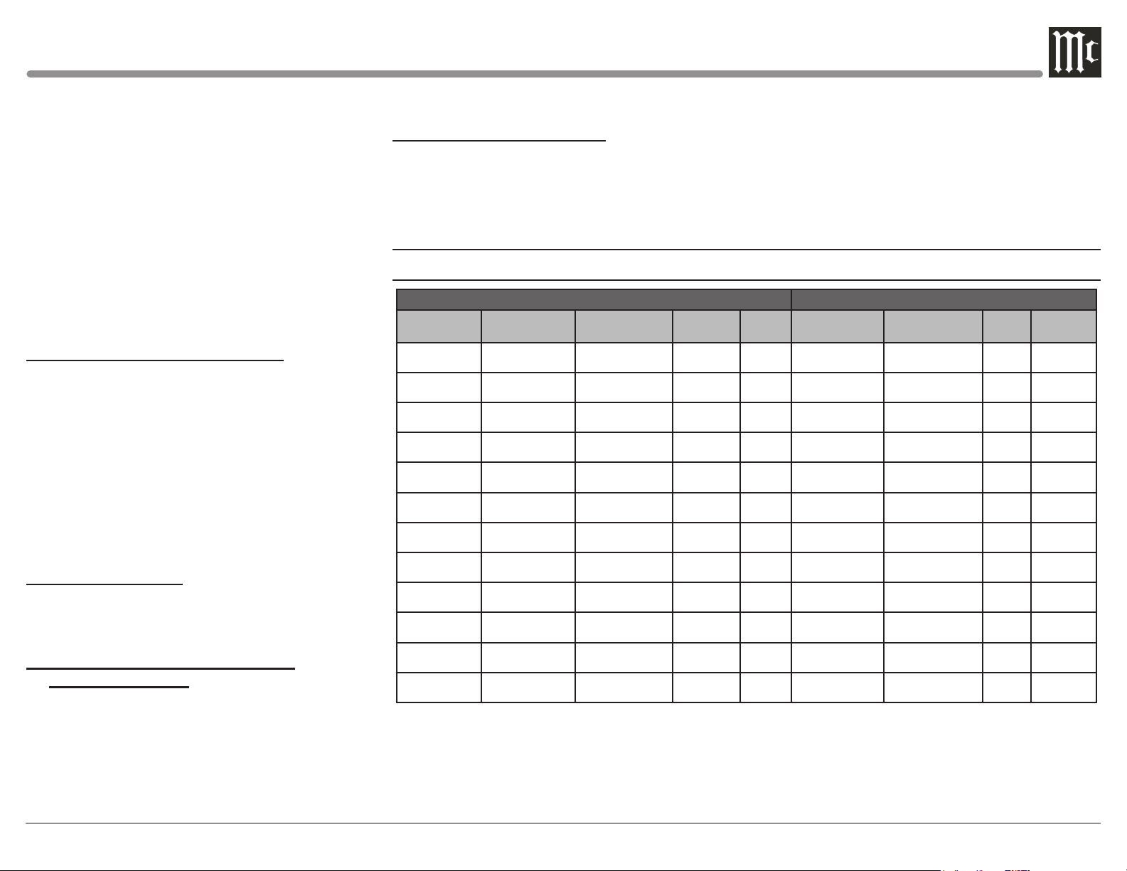
Input Assignment Chart
C12000 DEFAULT SETTINGS CONNECTION EXAMPLE SETTINGS
Input
Typ e
Unbalanced
Unbalanced
Unbalanced
Unbalanced
Balanced
Balanced
Balanced
Balanced
Balanced
Balanced
Phono
Phono
Input
Number
1 UNBA LAN CED
(L & R)
2 UNBA LAN CED
(L & R)
3 UNBA LAN CED
(L & R)
4 UNBA LAN CED
(L & R)
1 UNBA LAN CED
(L & R)
2 UNBA LAN CED
(L & R)
3 UNBA LAN CED
(L & R)
4 UNBA LAN CED
(L & R)
5 UNBALANCED
(L & R)
6 UNBA LAN CED
(L & R)
PH1
(L & R)
PH2
(L & R)
Input
Name
UNBA L 1 All (1 thru 8) Main 1 UNB ALA NCED
UNBA L 2 All (1 thru 8) Main 2 UNB ALA NCED
UNBA L 3 All (1 thru 8) Main 3 UNB ALA NCED
UNBA L 4 All (1 thru 8) Main 4 UNB ALA NCED
BAL 1 All (1 thru 8) Main 1 BAL ANCED
BAL 2 All (1 thru 8) Main 2 BAL ANCED
BAL 3 All (1 thru 8) Main 3 BAL ANCED
BAL 4 All (1 thru 8) Main 4 BAL ANCED
BAL 5 All (1 thru 8) Main 5 BALANCED
BAL 6 All (1 thru 8) Main 6 BAL ANCED
PHONO 1 ----- Main PH1
PHONO 2 ----- Main PH2
Data
Port
Power
Control
Input
Number
(L & R)
(L & R)
(L & R)
(L & R)
(L & R)
(L & R)
(L & R)
(L & R)
(L & R)
(L & R)
(L & R)
(L & R)
Input
Name
Tun e r 2 Main
SACD/CD 3 Main
Digital Audio Player ----- Main
Media Br idge 1 Main
Turntable ----- Main
Data
Port
Power
Control
13
Page 14
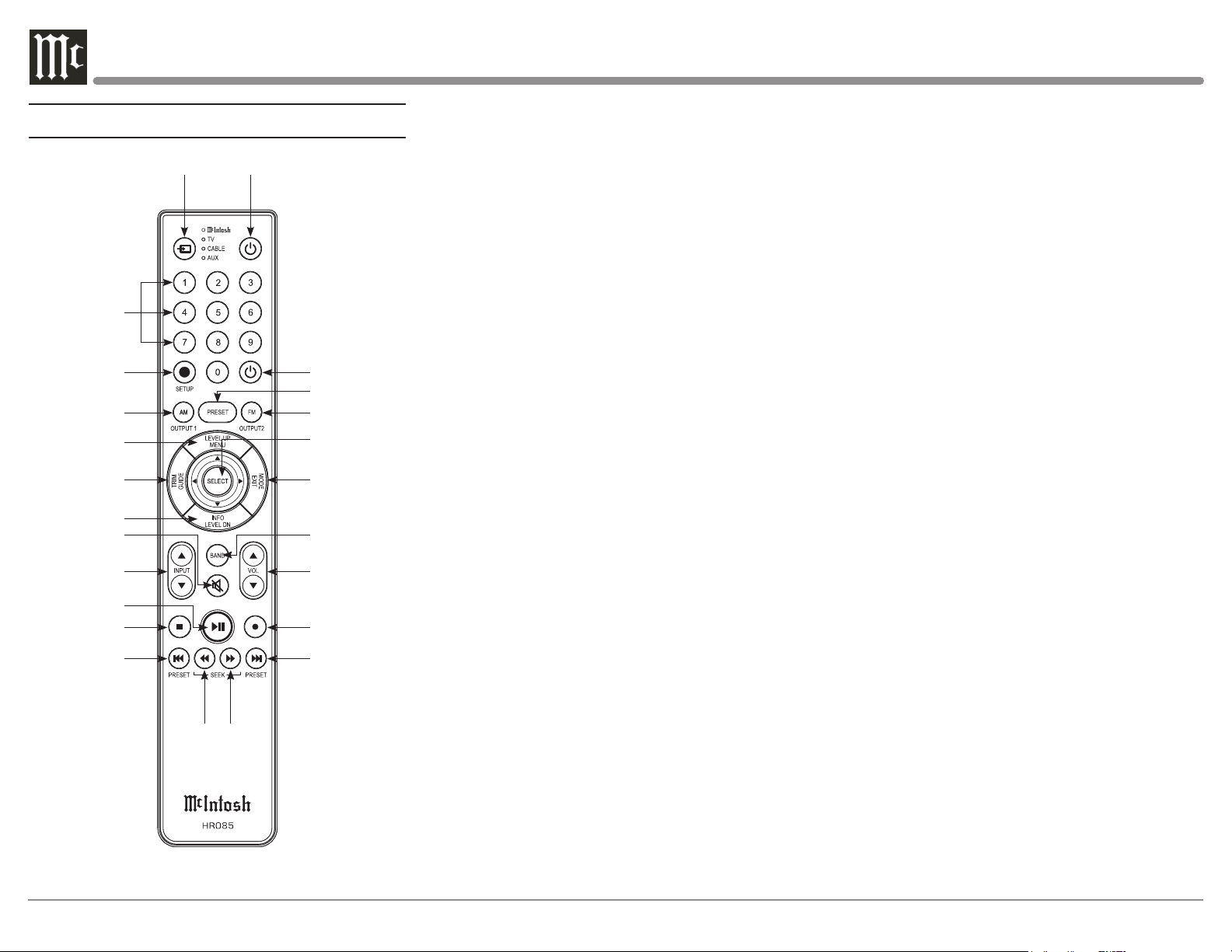
Navigating the Remote Control
1
2
3
4
5
6
7
8
9
10
11
12
13 14
24
23
22
21
20
19
18
17
16
15
1. Switch Device: Select different devices for remote
operation. Selected device is indicated by the LED
light when buttons are pressed.
2. Numbers: You can select tuner presets and manually enter disc tracks and radio stations – among other
numerical functions – using these buttons.
3. Setup: The Setup Button gives you access to the
additional functions for the buttons represented in
blue text. It’s like using the “Shift” key on a keyboard to access special characters above the number
keys. (Note: Cannot be used to enter Setup Mode.)
4. AM Tuner/Output 1: Access AM Tuner or press
Setup followed by this button to toggle Output 1.
5. Level Up/Menu: Adjusts trim functions settings.
Accesses menu on compatible devices.
6. Trim/Guide: Enters Trim Functions Menu. Opens
guide on compatible devices.
7. Info/Level Down: Adjusts trim functions settings.
Accesses info on compatible devices.
8. Mute: Mutes audio playback.
9. Input: Changes and selects different inputs.
10. Play/Pause: Pressing this button will halt playback
of active media, and it will resume from where it left
off if you press the button again.
11. Stop: Cancels media playback and resets progress
through it.
12. Previous/Previous Preset: You can go back to
your previous media selection by pressing this button. Also allows you to navigate to a previous tuner
preset.
13. Fast Reverse/Seek Down: Navigate backwards
through the current active media using this button.
This is also used to adjust the tuner downwards.
14. Fast Forward/Seek Up: Navigate forward through
the current active media using this button. This is
also used to adjust the tuner upwards.
15. Next/Next Preset: You can go forward to your
next media selection by pressing this button. Also
allows you to navigate to a later tuner preset.
16. Record: On devices with a record function, this
will begin recording the actively playing media.
17. Volume: Adjust the volume with these buttons.
18. Band: You will have the option to change the band
on your connected tuner or select certain options on
a variety of McIntosh models.
19. Mode/Exit: This will exit the Trim Functions
Menu. It will also display information or certain
options.
20. Select: Where applicable, you can press this button to select any highlighted option.
21. FM Tuner/Output 2: Access FM Tuner or press
Setup followed by this button to toggle Output 2.
22. Preset: Press this button followed by a number (0-
9) to immediately select that stored preset.
23. Power Off: Whichever device you have selected
on the remote control will turn off when you press
this button.
24. Power On: Whichever device you have selected
on the remote control will turn on when you press
this button.
Note: The included McIntosh HR085 Remote
Control has buttons used to control
multiple devices. While operating the C12000
Controller and Preamplifier with the remote,
nothing will happen when pressing buttons
that activate features not present on the these
units. Refer to HR085 Owner's Manual on
www.mcintoshlabs.com.
14
Page 15
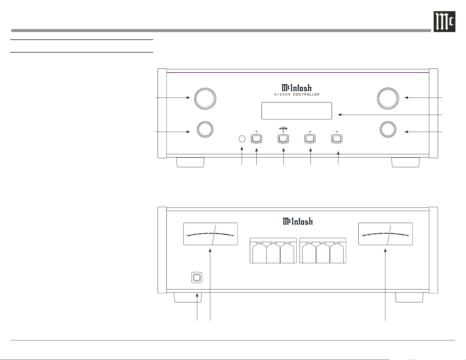
Front Panels
1C INPUT Control - used to select a source for
listening and recording. The control is also
used in the SETUP Modes
2C TRIM Control - allows selection of Trim
settings and is also used in the SETUP Mode
3C VOLUME Control - allows adjustment of the
listening level for both channels
4C INFORMATION DISPLAY - indicates the
Sources, Volume, other Audio Settings,
Operational Functions and Setup Mode
Settings
5C ADJUST Control - used for Trim Mode
Adjustments and also various SETUP
Functions
6C IR Sensor - receives commands from a Remote
Control
7C SETUP Push-button with indicator - activates
the Setup Mode allowing changes to the
default settings
8C HXD Push-button with indicator - activates the
Crossfeed Director Circuitry for Headphones
9C MUTE Push-button - mutes the audio from the
Loudspeakers and Headphones
10C STANDBY/ON Push-button with indicator -
switches the C12000 ON or OFF (Standby) and
resets the microprocessors
1P Connection for low impedance dynamic
headphones, for private listening
2P Meter indicates the Left Channel Output of the
Preamplifier
3P Meter indicates the Right Channel Output of
the Preamplifier
1C
2C
-60
HEADPH ONES
-50
INPUT
TRIM
MENU
-30
-40
dB
OU TP UT LE VE L
VOLUME
3C
Balanced 1
SETUP
70%
MUTE
ADJUS T
STANDBY / ON
RESET
4C
5C
6C 7C 8C 9C 10C
-20
-10
0
+3
C 12 0 0 0 P R E A MP L I F I E R
-60
-40
-50
-30
-20
dB
OU TP UT LE VE L
-10
0
+3
1P 2P 3P
15
Page 16
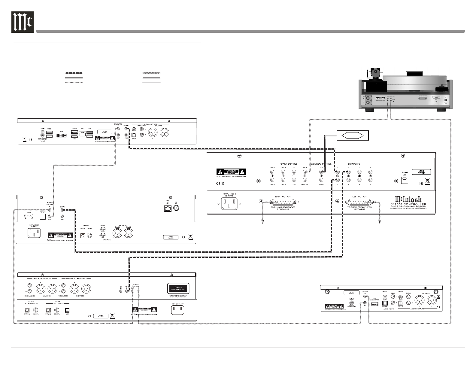
Controller Connection Diagram - Input and Control
Connection Legend:
Data Cable* Digital Signal Cable
Sensor/ Keypad Cable Ground Wire
Power Control Cable* Audio Signal Cable
Loudspeaker Cable
* 2 condu ctor shi elded w ith 1/8 inch s tereo m ini phon e plug on e ach end .
Media B ridge
AM /F M Tun er
To C12000 Pre ampli fier
Righ t Input
IR Sensor
To C12000 Pre ampli fier
Turntable with Moving Coil Cartridge
Left In put
16
SACD/CD Player
MCD5 50
SACD/C D PLAYER
McINTOSH LABORATORY, INC.,
BINGHAMTON, NY
HANDCRAFTED IN USA WITH US AND IMPORTED PARTS
WLAN ANT 1
Digit al Audio Player
WLAN ANT 2
Page 17
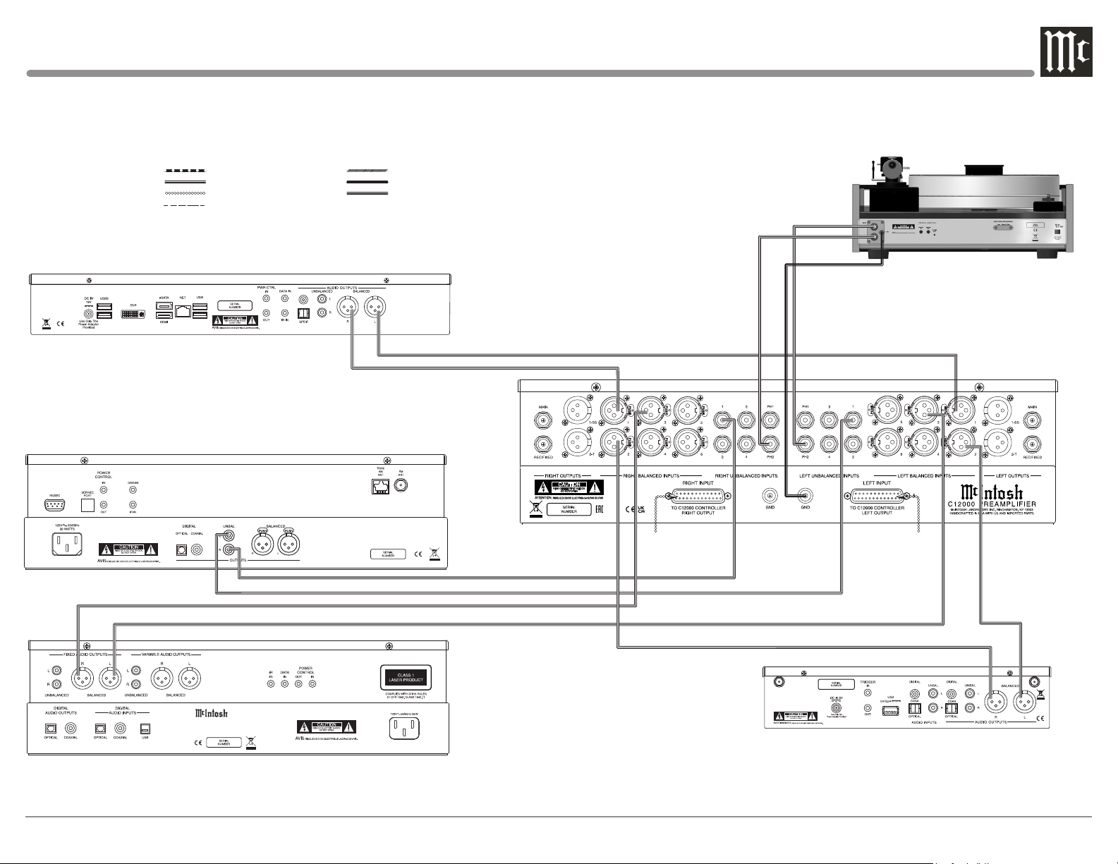
Connection Legend:
Data Cable* Digital Signal Cable
Sensor/ Keypad Cable Ground Wire
Power Control Cable* Audio Signal Cable
Loudspeaker Cable
* 2 condu ctor shi elded w ith 1/8 inch s tereo m ini phon e plug on e ach end .
Media B ridge
AM /F M Tun er
Turntable with Moving Coil Cartridge
SACD/CD Player
MCD5 50
SACD/C D PLAYER
McINTOSH LABORATORY, INC.,
BINGHAMTON, NY
HANDCRAFTED IN USA WITH US AND IMPORTED PARTS
From C12000 C ontrol ler
Right Output
WLAN ANT 1
From C12000 C ontrol ler
Left Output
Digit al Audio Player
WLAN ANT 2
17
Page 18
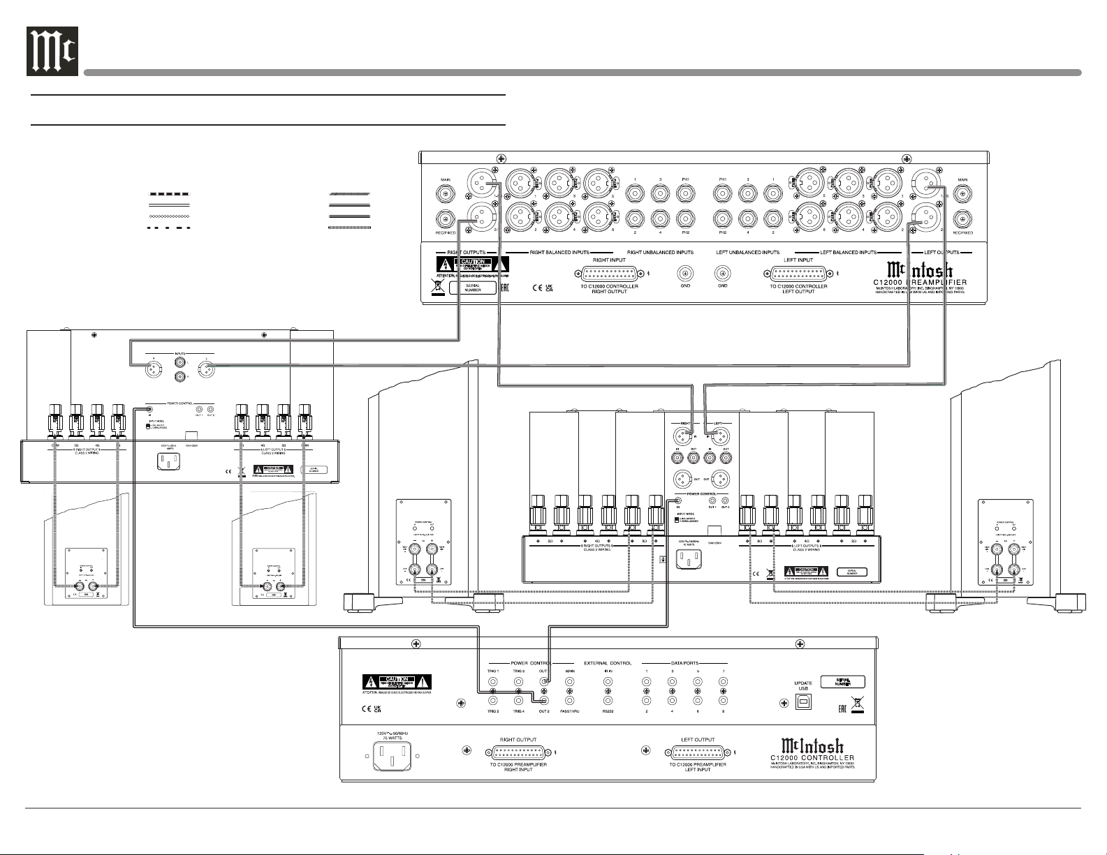
Preamplier Connection Diagram - Output Connections
Connection Legend:
Data Cable* Digital Signal Cable
Sensor/ Keypad Cable Ground Wire
Power Control Cable* Audio Signal Cable
Loudspeaker Cable RS232 Cable
* 2 condu ctor shi elded w ith 1/8 inch s tereo m ini phon e plug on e ach end .
Power Ampl ifie r - Secondar y Room
Power Ampl ifie r - Pri mar y Room
18
Right
Loudspeaker
System
-
Right Loudspeak-
6.6
Left
Loudspeaker
System
+
+
-
er System
-
+
Left Loud speaker
System
-
+
Page 19
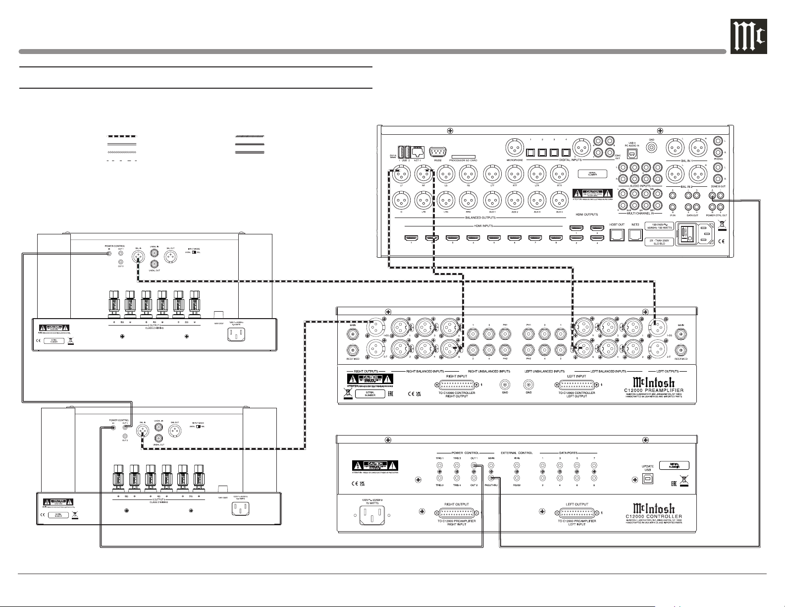
Preamplifier Connection Diagram - Passthru Connections
Connection Legend:
Data Cable* Digital Signal Cable
Sensor/ Keypad Cable Ground Wire
Power Control Cable* Audio Signal Cable
Loudspeaker Cable
* 2 condu ctor shi elded w ith 1/8 inch s tereo m ini phon e plug on e ach end .
Power Ampl ifie r (Lef t Front Cha nnel) - Main Room
Power Ampl ifie r (Rig ht Front Ch anne l) - Main Ro om
(Par tial Vie w)
(Par tial Vie w)
A/V Processor
19
Page 20
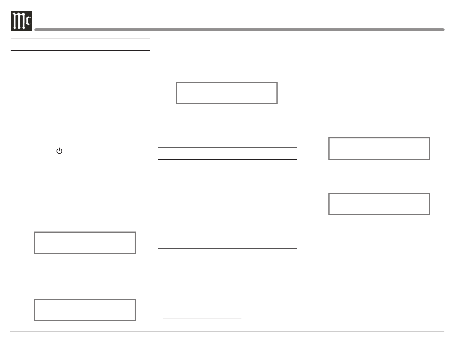
How to Operate the Setup Mode
S/N: AEE____
Your McIntosh C12000 has been factory configured
for default operating settings that will allow immediate
enjoyment of superb audio without the need for further
adjustments. If you wish to make changes to the
factory default settings, a Setup Feature is provided to
customize the operating settings using the Front Panel
Information Display. Refer to the C12000 Front Panel
Illustration on Page 15 while performing the following
steps.
Note: If the C12000 is currently On, proceed to step 2.
1. Press the STANDBY/ON Push-button on the Front
Panel or press the (Power ON) Push-button on the
Remote Control to switch On the C12000. The C12000
will go through a TUBE WARMUP (15 seconds)
with the Tubes in the C12000 glowing an amber color
and a brief startup initialization with the Front Panel
Information Display indicating the last used source
and volume setting. The illumination of the Tubes will
now glow a green color; this is followed by the volume
setting indication starting at zero, then increasing to
the last used volume setting. Refer to figure 1.
Balanced 1
15%
Figu re 1
2. Press the SETUP Push-button, rotate TRIM
(MENU) Control until the Front Panel Information
Display indicates “C12000, V_.__ - S/N: AEE_ _ __”
(or higher Firmware version). Refer to figure 2.
C12000 V1.00
Figu re 2
3. Rotate the TRIM Control to select the next Setup
Mode Menu item,
“SETUP: Balanced 1, On/Name (Hold SETUP)”.
Refer to figure 3. Continue to rotate the INPUT
CONTROL to view the other SETUP Mode Options.
SETUP: Balanced 1
On/Name (Hold SETUP)
Figu re 3
4. To exit from the SETUP Mode, press the SETUP
Push-button and the Front Panel Display will revert
back to its normal display. Refer to figure 1.
Firmware Version
The C12000 functionality is controlled by internal
software that is know as Firmware. The Version of the
Firmware in the C12000 can be identified at any time
by utilizing the Setup Mode.
1. Press the SETUP Push-button to enter Setup
Mode.
2. Referring to the Front Panel Information Displaythe number after the character “V” is the Firmware
number. Refer to figure 2.
3. To exit the Setup Mode, press the SETUP Pushbutton.
Input Settings
The C12000 provides the ability to switch unused
INPUTS Off (or back On if they have been previously
switched Off). The default INPUT Names can be
changed to match the name of the component connected to it or any other custom name desired (within
10 Characters).
INPUT SWITCHED ON/OFF:
In the following example, the Unbalanced 4 Input
will be switched Off.
Note: When an INPUT is swiched Off, its name will no
longer appear on the Front Panel Information Display when
using the INPUT Control (Front Panel or Remote Control).
1. Press the SETUP Push-button to enter the SETUP
MODE. Refer to figure 2.
2. Rotate the TRIM Control until “SETUP: _____,
On/Name (Hold SETUP)” appears on the Information
Display. Refer to figure 3.
3. Then rotate the INPUT Control to select the
Unbalanced 4 Input. Refer to figure 4.
SETUP: Unbalanced 4
On/Name (Hold SETUP)
Figu re 4
4. To switch the Unbalanced 4 Input Off, rotate the
ADJUST Control until the display indicates
“SETUP: Unbalanced 4, Off”. Refer to figure 5.
SETUP: Unbalanced 4
Off
Figu re 5
5. Exit the SETUP Mode by pressing the SETUP
Push-button.
In the following example, the Unbalanced 4 Input
will be switched On.
Note : When an INPUT is swiched ON, its name will
appear on the Front Panel Information Display when using
the INPUT Control (Front Panel or Remote Control).
6. Press the SETUP Push-button to enter the SETUP
MODE. Refer to figure 2..
7. Rotate the TRIM Control until “SETUP: ____ _,
On/Name (Hold SETUP)” appears on the Information
Display. Refer to figure 3.
8. Rotate the INPUT Control to select the
Unbalanced 4 Input. Refer to figure 5.
20
Page 21
9. To switch the Unabalanced 4 Input On, rotate the
ADJUST Control until the display indicates SETUP:
Unbalanced 4, On/Name (Hold SETUP)”. Refer to
figure 4 on Page 20.
10. Exit the SETUP Mode by pressing the SETUP
Push-button.
R E NA M E I N PU T:
In the following example, the Balanced 1 Input will
be renamed to match up with the component connected.
The C12000 Default Input Names as indicated on
the Front Panel Display can be customized to a different name up to 12 characters long (TUNER, CD
PLAYER, etc.). The available characters for renaming
the input include the following: ! < > * , / - _ 0 1 2 3 4
5 6 7 8 9 A B C D E F G H I J K L M N O P Q R S T
U V W X Y Z .
In the following example, the Balanced 1 Input will
be renamed to “MEDIA BRDG”.
11. Press the SETUP Push-button to enter the
SETUP MODE. Refer to figure 2, on Page 20.
12. Rotate the TRIM Control until “SETUP: _____,
On/Name (Hold SETUP)” appears on the Information
Display. Then rotate the INPUT Control to select the
“Balanced 1” Input. Refer to figure 6.
SETUP: Balanced 1
On/Name (Hold SETUP)
Figu re 6
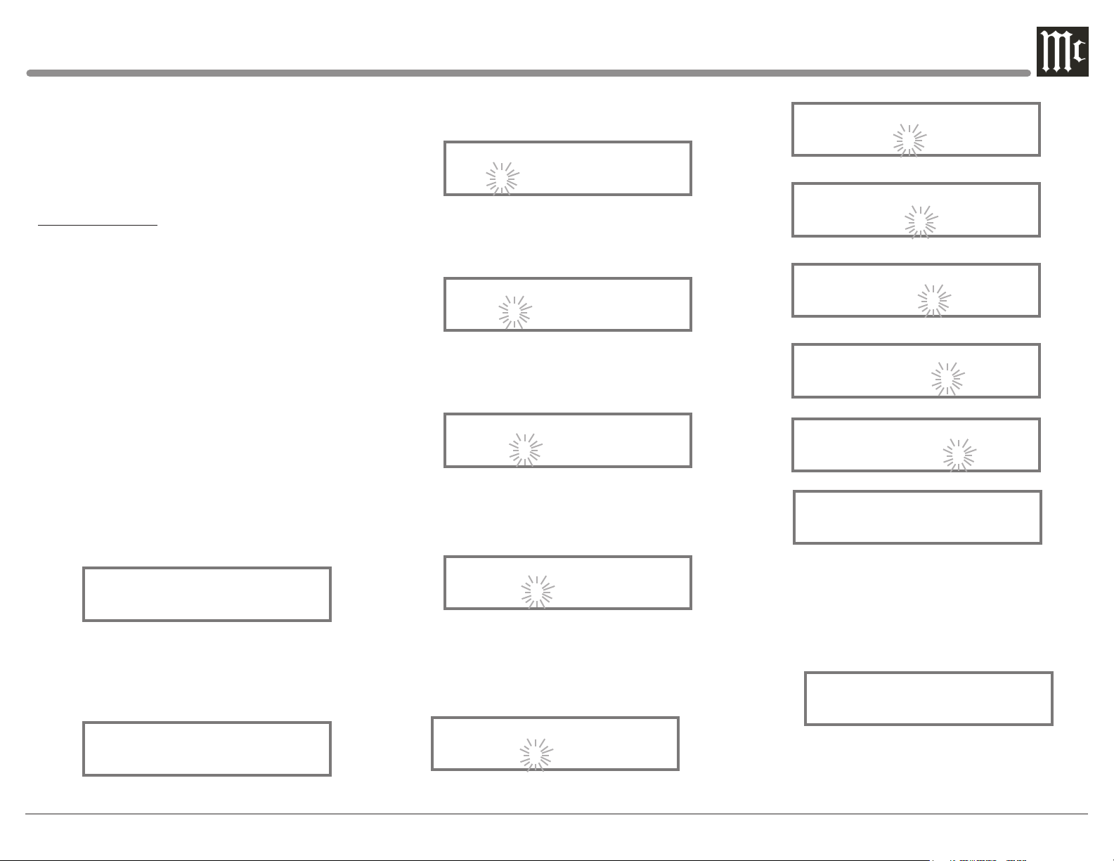
13. Press and hold in the SETUP Push-button until
“RENAME: Balanced 1, >Balanced 1 < ” appears on
the Display. The character “B” is flashing to indicate
it is ready to be changed. Refer to figure 7.
RENAME: Balanced 1
>Balanced 1 <
Figu re 7
14. Rotate the ADJUST Control to change the char-
acter “B” to “M”. Refer to figure 8.
RENAME: Balanced 1
>Malanced 1 <
Figu re 8
15. Rotate the TRIM Control until the character “a”
is flashing, then rotate the ADJUST Control to change
the character “a” to “E”. Refer to figure 9.
RENAME: Balanced 1
>MElanced 1 <
Figu re 9
16. Rotate the TRIM Control until the character “l”
is flashing, then rotate the ADJUST Control to change
the character “l” to “D”. Refer to figure 10.
RENAME: Balanced 1
>MEDanced 1 <
Fig u r e 10
17. Rotate the TRIM Control until the character “a”
is flashing, then rotate the ADJUST Control to change
the “a” character to “I”. Refer to figure 11.
RENAME: Balanced 1
>MEDInced 1 <
Fi g u re 11
18. Repeat steps 14 thru 17 until the new name of “
RENAME: Balanced 1, >MEDIA BRDG <” is indicated on the Front Panel Display. Refer to figures 12
th r u 18.
RENAME: Balanced 1
>MEDIAced 1 <
Figu re 12
RENAME: Balanced 1
>MEDIA ed 1 <
Figure 13
RENAME: Balanced 1
>MEDIA Bd 1 <
Figu re 14
RENAME: Balanced 1
>MEDIA BR 1 <
Fig ure 15
RENAME: Balanced 1
>MEDIA BRD1 <
Figu re 16
RENAME: Balanced 1
>MEDIA BRDG <
Fig u re 17
RENAME: Balanced 1
>MEDIA BRDG <
Figure 18
19. To save the new name, press and hold in the
SETUP Push-Button until
“SETUP: MEDIA BRDG , ON/Name (Hold SETUP)”
appears on the Front Panel Information Display. Refer
to figure 19.
SETUP: MEDIA BRDG
On/Name (Hold SETUP)
Figure 19
21. Exit the SETUP Mode by pressing the SETUP
Push-button.
21
Page 22
SETUP: OUTPUT 2
SETUP:MUTE WITH HDPH
SETUP:MUTE WITH HDPH
Output Settings
SETUP: OUTPUT 2
SETUP:MUTE WITH HDPH
SETUP:MUTE WITH HDPH
SETUP:MUTE WITH HDPH
SETUP:MUTE WITH HDPH
Note: Output 1 (1-SS) uses Solid State amplification,
Output 2 (2-T) uses Tube amplification.
The Output Settings provide the ability to change
how the C12000 Output 1 and Output 2 function.
OUTPUT 1 and 2:
By defaut OUTPUT 1 and 2 are set to go On/Off by
using the Front Panel TRIM and ADJUST Controls
or the OUTPUT 1 and 2 Push-buttons on the Remote
Control. If it is desirable to have OUTPUT 1 and/or
2 always On regardless of the TRIM setting, perform
the following:
1. Press the SETUP Push-button to enter the SETUP
MODE. Refer to figure 2..
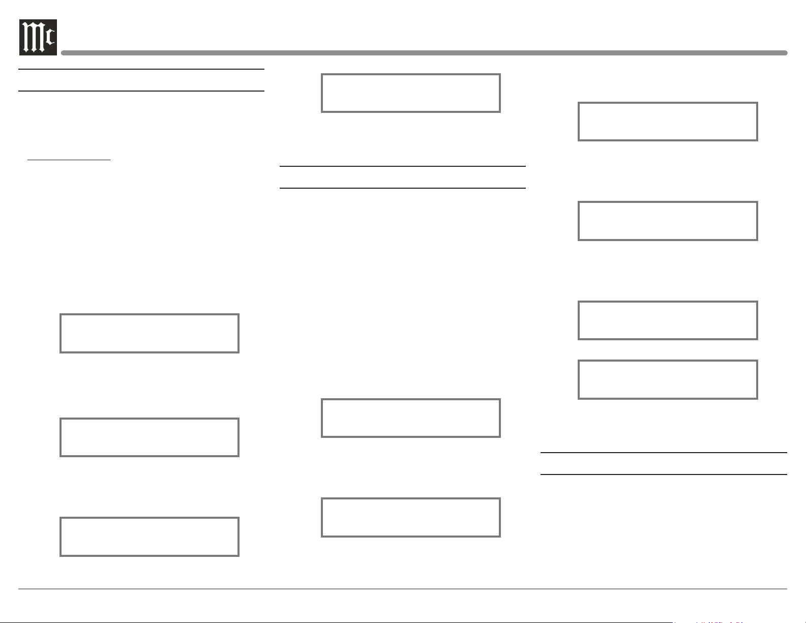
2. Rotate the TRIM Control until “SETUP: OUTPUT 1, Switched” appears on the Information Display.
Refer to figure 20.
SETUP: OUTPUT 1
Switched
Figu re 20
3. Rotate the ADJUST Control until “SETUP:
OUTPUT 1, Unswitched” appears on the Information
Display. Refer to figure 21.
Unswitched
Figu re 23
5. Exit the SETUP Mode by pressing the SETUP
Push-button.
Headphone Settings
The C12000 has the ability to automatically mute
the Output Jacks and/or Connectors when a Headphone Cable Plug is inserted into the C12000 Front
Panel HEADPHONES Jack. The Output Default Settings are: MAIN - Unmuted
OUTPUT 1 - Muted
OUTPUT 2 - Muted
In the following examples the MAIN Output Jacks
will Mute and the OUTPUT 1 Connectors will not
Mute when Headphones are connected:
1. Press the SETUP Push-button to enter the SETUP
MODE. Refer to figure 2.
2. Rotate the TRIM Control until “SETUP: MUTE
WITH HDPH, Main = Unmuted ” appears on the
Information Display. Refer to figure 24.
setting to “SETUP: MUTE WITH HDPH, Output 1 =
Muted”. Refer to figure 26.
Output 1 = Muted
Figu re 26
5. Rotate the ADJUST Control to change the current
setting to “SETUP: MUTE WITH HDPH, Output
1 = Unmuted”. Refer to figure 27.
Output 1 = Unmuted
Figu re 27
6. In a similar manner, perform steps 4 and 5 to
change the OUTPUT 2 setting. Refer to figures 28
and 29.
Output 2 = Muted
Figu re 28
Output 2 = Unmuted
Figu re 29
SETUP: OUTPUT 1
Unswitched
Fig ur e 21
4. In a similar manner, perform steps 2 and 3 to
change the OUTPUT 2 setting. Refer to figures 22 and
23.
Switched
Figu re 22
22
Main = Unmuted
Figu re 24
3. Rotate the ADJUST Control to change the current
setting to “SETUP: MUTE WITH HDPH, Main =
Muted”. Refer to figure 25.
Main = Muted
Figu re 25
4. Rotate the INPUT Control to change the current
7. Exit the SETUP Mode by pressing the SETUP
Push-button.
Power Control Triggers
In the first example, the Power Control Triggers 1
and 2 will be assigned to Output 1 and 2 respectively:
1. Press the SETUP Push-button to enter the SETUP
MODE. Refer to figure 2..
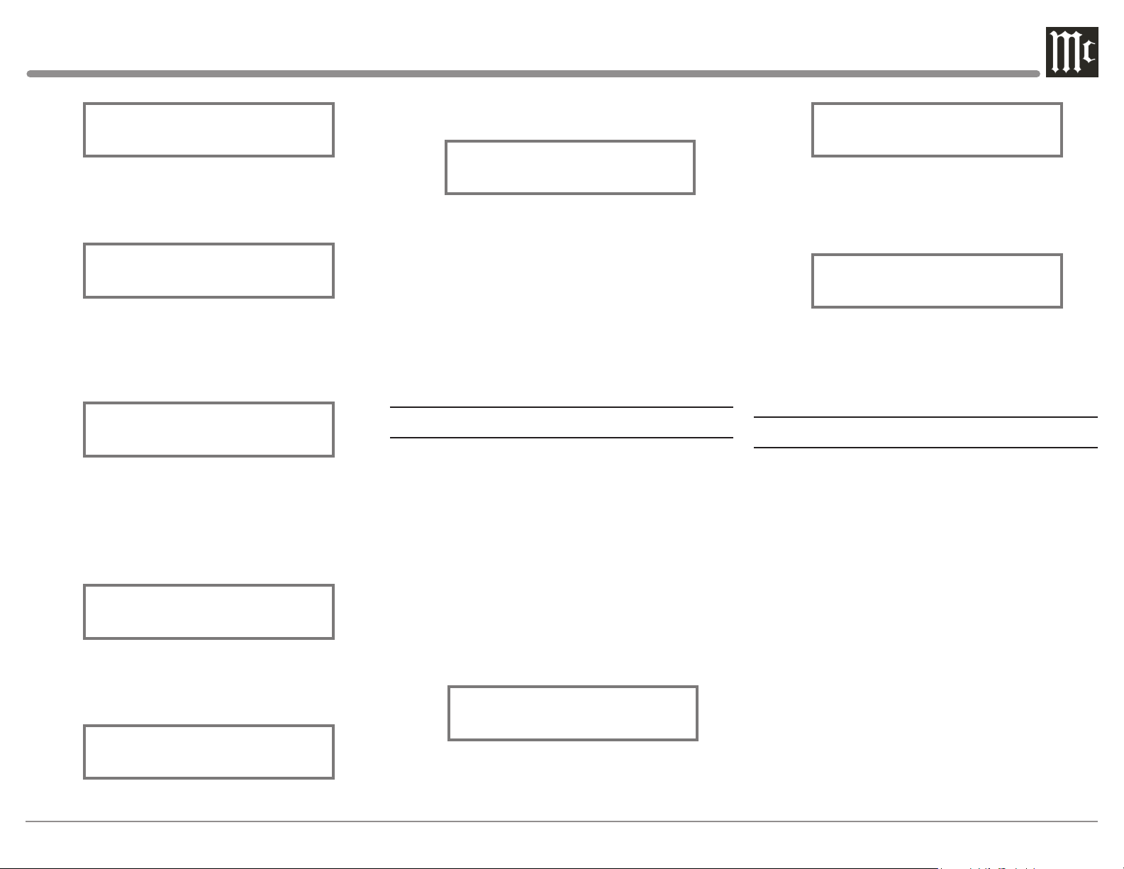
2. Rotate the TRIM Control until SETUP:
TRIGGER 1, MAIN” appears on the Display. Refer to
figure 30.
Page 23
SETUP: TRIGGER 1
SETUP: TRIGGER 2
Main
Figu re 30
3. Rotate the ADJUST Control to select Output 1
from the available additional selections including
Output 2 or Input. Refer to figure 31.
SETUP: TRIGGER 1
Output 1
Fig u re 31
4. To change the Trigger 2 setting from Main to
OUTPUT 2, first rotate the INPUT Control to select
TRIGGER 2. Then Rotate the ADJUST Control to
select Output 2. Refer to figure 32.
7. Rotate the VOLUME Control to select “Balanced
1: ON”. Refer to figure 35.
SETUP: TRIGGER 3
Balanced 1: ON
Figure 35
8. Exit the SETUP Mode by pressing the SETUP
Push-button.
By default the Power Control TRIGger 1 thru
TRIGger 4 Outputs function the same as the MAIN
Power Control Jack, switching On/Off with the
C12000. Triggers 1 thru 4 are also reassignable to
activate when Output 1 or 2 is selected. All four
Triggers can also be assigned to a given Input or
Inputs.
SETUP: DATA PORT 1
Balanced 1 Data
Figure 37
4. To assign additional Data Ports, first rotate the
INPUT Control to select the Data Port and then rotate
the ADJUST Control to select the desired Input. Refer
to figure 38.
SETUP: DATA PORT 2
Unbalanced 1 Data
Figu re 38
5. In a similar manner, assign any additional Data
Ports.
6. Exit the SETUP Mode by pressing the SETUP
Push-button.
Output 2
Figure 32
The second example will use selection of the Trigger
3 to activate when the BAL 1 Input is selected:
5. Rotate the INPUT Control to select “SETUP:
TRIGGER 3, Main” appears on the Display. Refer to
figu re 33.
SETUP: TRIGGER 1
Main
Figure 33
6. Rotate the ADJUST Control until “SETUP:
TRIGGER 3, Balanced 1: OFF” appears on the
Display. Refer to figure 34.
SETUP: TRIGGER 3
Balanced 1: OFF
Figure 34
Data Ports
Data Ports Connections between the C12000 and a
McIntosh Source Component allow for basic function
control of the source component using the C12000
supplied Remote Control. By default, all eight Data
Ports are sent the same Data for the selected source.
To dedicate a Data Port for only one source compo-
nent (BAL 1 Input will be assigned to Data Port 1)
perform the following Steps:
1. Press the SETUP Push-button to enter the SETUP
MODE. Refer to figure 2..
2. Rotate the TRIM Control until “SETUP: Data
Port 1, All Data” appears on the Information Display.
Refer to figure 36.
SETUP: DATA PORT 1
All Data
Figu re 36
3. Rotate the ADJUST Control until “SETUP:
DATA PORT 1, Balanced 1 Data” appears on the
Display. Refer to figure 37.
Passthru
When the C12000 is part of a Home Theater or
Multichannel Audio System the Right and Left Front
Channels from an Audio/Video Processor or Surround
Decoder can “Passthru” the C12000 and onto its associated Power Amplifier(s). The Setup Mode allows selection of the specified C12000 Input to be used for the
Right and Left Front Channels. In the example below,
the Right and Left Front Channels from the Audio/
Video Processsor will be connected to the BALanced 6
Input Connectors on the C12000. Refer to Pages 16 and
17 for additional connection information.
Notes: 1. The Phono Inputs are not assignable as a
Passthru Input.
2. If Balanced Input 6 is already assigned to a given
Input, it will not appear in the list of available Inputs.
3. When one of the Unbalanced Inputs is selected as a
Passthru Input, it is advisable to remove it from the Input
List by switching it Off. Refer to “Input Settings” on Page 20.
23
Page 24
SETUP: IR Codes
1. Press the SETUP Push-button to enter the SETUP
115200 Baud
SETUP: Front IR
SETUP: Front IR
MODE. Refer to figure 2..
2. Rotate the TRIM Control until
“SETUP: Passthru, Off ” appears on the Information
Display. Refer to figure 39.
Figure 39
3. Rotate the ADJUST Control to select
“Balanced 6” Input. Refer to figure 40.
SETUP: Passthru
Balanced 6
Figu re 40
4. Exit the SETUP Mode by pressing the SETUP
Push-button.
Comm Port Baud Rate
The C12000 may be remotely controlled from other
equipment connected to the Rear Panel RS232 Jack.
The speed at which the C12000 communicates (8 bit,
no parity and 1 stop bit) with other equipment is adjustable from 9,600 bits per second to 115,200 bits per
second. To change from the default speed of 115,200
bits per second, perform the following steps:
1. Press the SETUP Push-button to enter the SETUP
MODE. Refer to figure 2.
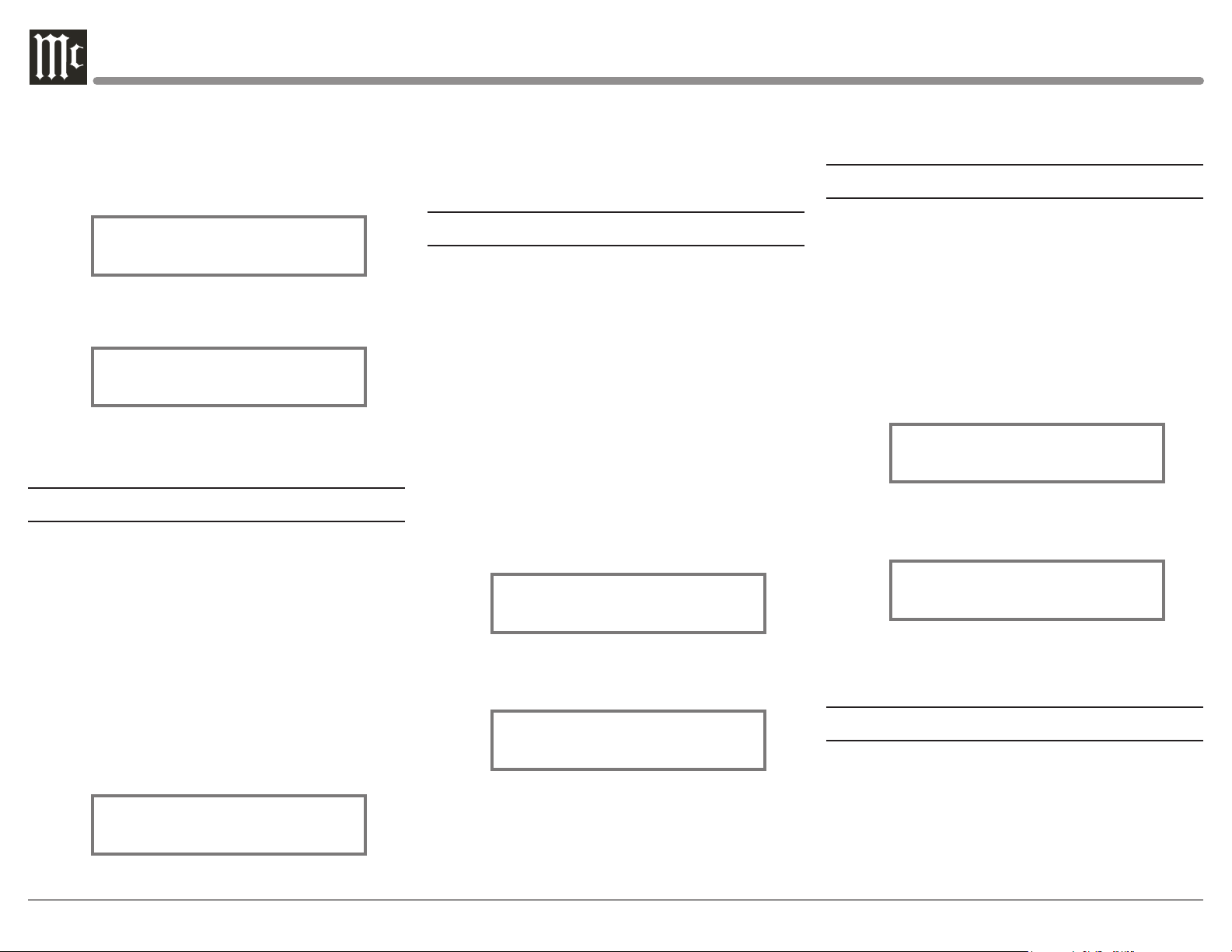
2. Rotate the TRIM Control until “SETUP: RS232,
115200 Baud” appears on the Information Display.
Refer to figure 41.
SETUP: RS232
Figu re 41
24
3. Rotate the ADJUST Control to select the desired
Baud Rate Speed (115200 thru 9600).
4. Exit the SETUP Mode by pressing the SETUP
Push-button.
Remote Control Codes
The Remote Control included with the C12000
utilizes the NORMAL McIntosh Control Codes. The
Second Set of Control Codes the C12000 will respond
to is referred to as the ALTERNATE Codes. The Alternate Codes are used when the C12000 is used in the
same location as another McIntosh Preamplifier and/or
A/V Processor. This will prevent the Remote Control
from affecting the operation of both units at the same
time. To activate the Remote Control ALTERNATE
Codes perform the following steps:
1. Press the SETUP Push-button to enter the SETUP
MODE. Refer to figure 2.
2. Rotate the TRIM Control until “SETUP: IR
Codes, Normal” appears on the Information Display.
Refer to figure 42.
Normal
Figu re 42
3. Rotate the ADJUST Control to select the Alternate Codes. Refer to figure 43.
Figure 43
4. It is now necessary to change the HR085 Remote
Control over to the Alternate Codes. Information on
the HR085 Remote Control is available for download
from the McIntosh Web Site:
http://www.mcintoshlabs.com/
5. Exit the SETUP Mode by pressing the SETUP
Push-button.
IR Sensor
The C12000 Front Panel Sensor, which receives
the signals from the HR085 Remote Control, can be
switched off to prevent interference when an external
IR Sensor is connected. To de-activate the Front Panel
IR Sensor perform the following steps:
1. Press the SETUP Push-button to enter the SETUP
MODE. Refer to figure 2.
2. Rotate the TRIM Control until “SETUP: Front
IR, Enabled” appears on the Information Display.
Refer to figure 44.
Enabled
Figu re 44
3. Rotate the VOLUME (ADJUST) Control to select
Disabled. Refer to figure 45.
Disabled
Figure 45
4. Exit the SETUP Mode by pressing the SETUP
Push-button.
Power Mode
The C12000 incorporates an Auto Off Feature,
which automatically places the preamplifier into the
Power Saving Standby/Off Mode. This occurs approximately 30 minutes after there has been an absence of
audio input or user activity (includes changes to any
of the Operation Functions such as source selection,
volume adjustment, etc). If it is desirable to disable the
Page 25
FACTORY RESET
FACTORY RESET
Auto Off Feature perform the following steps:
FACTORY RESET
(Hold SETUP)
1. Press the SETUP Push-button to enter the SETUP
MODE. Refer to figure 2.
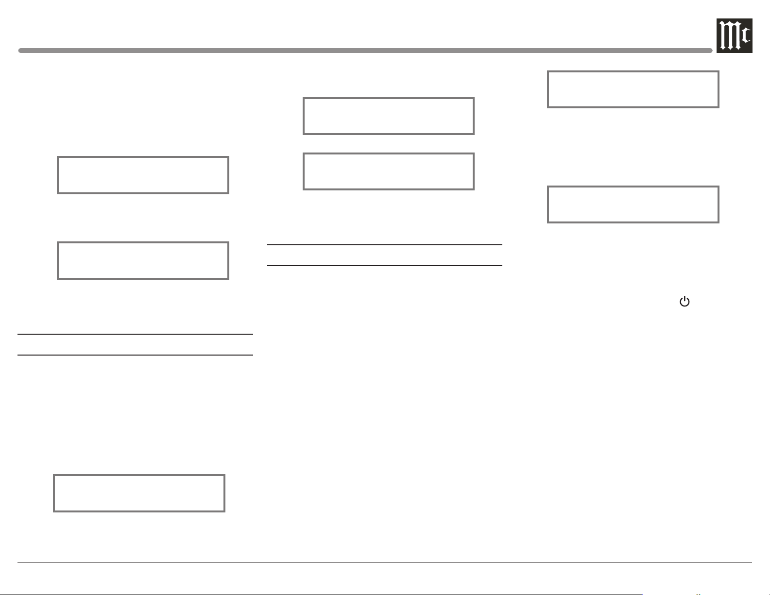
2. Rotate the TRIM Control until “SETUP: Auto
Off, Enabled” appears on the Information Display.
Refer to figure 46.
Figure 46
3. Rotate the ADJUST Control to select Disabled.
Refer to figure 47.
Figure 47
4. Exit the SETUP Mode by pressing the SETUP
Push-button.
Factory Reset
If it becomes desirable to reset all the adjustable set-
tings (Setup and Trim Settings) to the factory default
values, perform the following steps:
1. Press the SETUP Push-button to enter the SETUP
MODE. Refer to figure 2..
2. Rotate the TRIM Control until “FACTORY RE-
SET, (Hold SETUP)” appears on the Information
Display. Refer to figure 48.
Figu re 48
the Information Display, then release the SETUP
Push-button. Refer to figures 49 and 50.
In Progress
Figu re 49
Completed!
Figure 50
4. Press the Front Panel STANDBY/ON Push-button
to switch the C12000 on.
How to Operate the C12000
Power On and Off
The Red LED above the STANDBY/ON Push-button
lights to indicate the C12000 is in Standby mode.
To switch ON the C12000, press the STANDBY/ON
Push-button on the Front Panel or the (Power On)
Push-button on the Remote Control. The C12000 will
go through a TUBE WARMUP (15 seconds) with the
Tubes in the C12000 Preamplifier glowing an amber
color, a brief startup initialization with the Front Panel
Information Display indicating the last used source
and volume setting. The illumination of the Tubes will
now glow a green color; this is followed by the volume
setting indication starting at zero, then increasing
to the last used volume setting. To switch OFF the
C12000, press the STANDBY/ON Push-button on the
Front Panel or the OFF Push-button on the Remote
Control.
Note: For an explanation of the Remote Control
Push-button functions, refer to Page 14.
Balanced 1
15%
Fig ur e 51
Source Selection
Rotate the Front Panel INPUT Control to select the
desired source or press the INPUT Upp or Downq
Push-button on the Remote Control. Refer to figure
52.
Unbalanced 1
15%
Figure 52
Volume Control
Rotate the Front Panel VOLUME Control or use the
VOLUME Upp or Downq Push-buttons on the Re-
mote Control for the desired listening level.
Trim Functions
The C12000 has nine different Trim Selections with
Adjustments. The Trim Selections include Balance,
Input Trim Level, Output 1, Output 2, Meter Lights,
Display Brightness, Phono Cartridge (MC & MM)
Loading (when the Input is Selected) , and Headphone
HXD Mode and Headphone Gain. The Trim Settings
are stored in memory independently for each Input
Source Selected, except the Meter Illumination, Display Brightness and Headphone Settings of which are
the same for all inputs.
Note: Selection and Adjustment of all Trim Functions
may be performed by rotating the Front Panel
TRIM Control and then use the ADJUST Control to change the setting. Remote Control TRIM
Push-Button together with the LEVEL UP / Down
Push-button may also be used. Refer to Remote
Control diagram on Page 14.
3. Press and hold in the SETUP Push-button until
“FACTORY RESET, In Progress” appears on
25
Page 26
BALANCE
||
¦
L BALANCE R
OUTPUT 2
OUTPUT 2
INPUT TRIM
INPUT TRIM
INPUT TRIM
Listening balance varies with different program sources, room acoustics and listening positions relative to
the Loudspeakers. Use the Balance (Trim Function) as
needed to achieve approximately equal listening volume levels in each Loudspeaker. To adjust the Balance
perform the following:
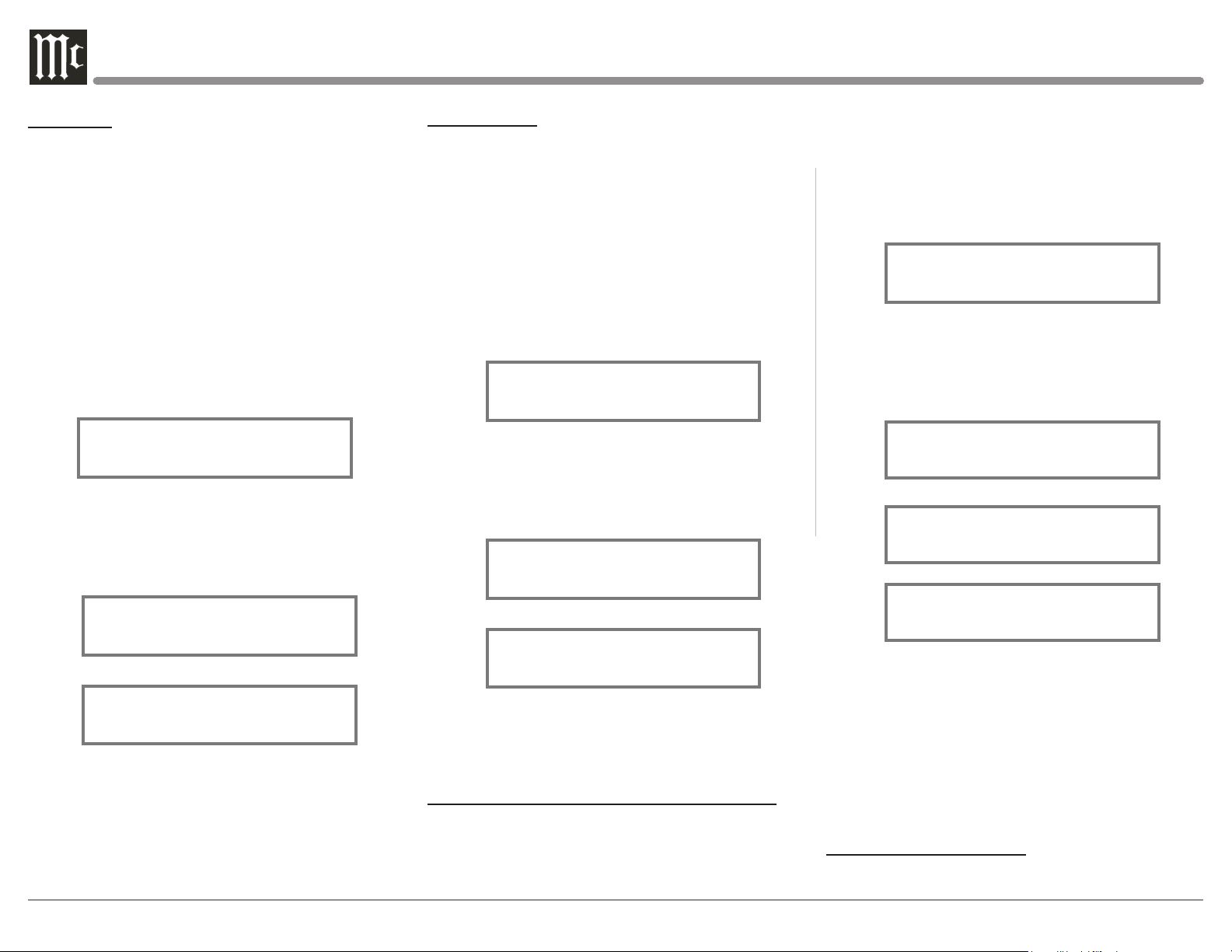
1. Press the TRIM Push-button repeatedly on the
Remote Control until “L BALANCE R” appears
on the Front Panel Information Display. Refer to
figu re 53.
Note: The Front Panel TRIM and ADJUST Controls
may also be used.
Figure 53
2. Press the LEVEL UP / DOWN Push-buttons on
the Remote Control to emphasize the Right Chan-
nel (refer to figure 54) or the Left Channel (refer to
figure 55).
¦
¦ ¦ ¦
¦ ¦ ¦
Figu re 54
¦ ¦ ¦
¦ ¦ ¦ ¦ ¦
The Front Panel Display indicates the Balance changes
are from 0 to 50dB. After approximately 10 seconds
the Information Display returns to indicate the Source
Selection and Volume Level. To verify the Balance
setting without changing it, use the TRIM Push-button
and select Balance.
26
¦
Fig u re 55
TRIM LEVEL
Source Components can have slightly different volume
levels resulting in the need to readjust the C12000
Volume Control when switching between different
sources. The C12000 allows the adjustment of levels
for each of the Source Inputs for the same relative
volume. To adjust the Trim Level for the currently
selected Input Source perform the following steps:
1. Select “INPUT TRIM” as indicated on the Front
Panel Information Display. Refer to figure 56.
0.0 dB
Figu re 56
2. Adjust the Trim Level of each Input to match the
average volume level of the Input most frequently
listened to. The range of adjustment is ± 6.0dB in
half dB steps. Refer to figures 57 and 58.
-2.5 dB
Figure 57
+4.0 dB
Figu re 58
After approximately 10 seconds the Information
Display returns to indicate the Source Selection and
Volume Level.
OUTPUT 1 (Solid State) and OUTPUT 2 (Tube)
The Rear Panel Output 1 (Solid State) and Output
2 (Tube) Connectors (along with the Power Control
Output 1 and 2) can be switched On or Off by using
the TRIM FUNCTIONS OUTPUT 1 and OUTPUT
2. The default settings for TRIM OUTPUT 1 and
OUTPUT 2 is ON. To change the setting perform the
following:
1. Select “OUTPUT 1” as indicated on the Front
Panel Information Display. Refer to figures 59
.
OUTPUT 1
ON
Figure 59
2. Either rotate the Front Panel ADJUST Control or
LEVEL UP / Down Push-button on the Remote
Control to change the setting for OUTPUT 1 or
OUTPUT 2. Refer to figures 60 thru 62.
OUTPUT 1
OFF
Figure 60
ON
Figure 61
OFF
Figu re 62
Note: The OUTPUT 1 and OUTPUT 2 Remote
Control Push- buttons may also be used. Refer
to the Remote Control diagram on Page 14 for
additional information.
After approximately 10 seconds the Information
Display returns to indicate the Source Selection and
Volume Level.
METER ILLUMINATION
The C12000 Front Panel Meter Illumination may be
Page 27
BRIGHTNESS
HEADPHONE HXD
HEADPHONE HXD
switched On or Off by performing the following:
METER LIGHTS
METER LIGHTS
BRIGHTNESS
HEADPHONE GAIN
HEADPHONE GAIN
HEADPHONE GAIN
1. Select “METER LIGHTS, On” as indicated on the
Front Panel Information Display. Refer to figure
63.
DISPLAY
Figu re 66
40O - 150O
Figu re 69
On
Figu re 63
2. Switch Off the Meter Illumination. Refer to
figure 64.
Off
Figu re 64
After approximately 10 seconds the Information
Display returns to indicate the Source Selection and
Volume Level.
Notes: 1. Meter Illumination of recent McIntosh Power
Amplifiers will also switch On/Off when connected to
the C12000 via a power control cable.
2. Some A/V Processors will provide an On/Off Control Signal when the C12000 Passthru Input Jack is
connected to the A/V Processor via the power control
cable.
INFORMATION DISPLAY BRIGHTNESS
The Brightness Level of C12000 Front Panel Information Display can be adjusted from bright to dim by
performing the following:
1. Select “DISPLAY BRIGHTNESS” as indicated
on the Front Panel Information Display. Refer to
figure 65.
DISPLAY
Figu re 65
2. Reduce the Brightness level by adjusting the
TRIM LEVEL. Refer to figure 66.
After approximately 10 seconds the Information
Display returns to indicate the Source Selection and
Volume Level.
HEADPHONE HXD SELECTION
The C12000 Internal Headphone Amplifier incorporates McIntosh HXD Circuitry bringing acoustical
depth and spatiality of music normally heard with
loudspeakers, to your headphones. It can be switched
On or Off as follows:
1. Select the “HEADPHONE HXD, ___” TRIM
FUNCTION. Refer to figures 67 and 68.
Off
Figu re 67
On
Figu re 68
2. Select either ON or OFF.
HEADPHONE GAIN SELECTION
The C12000 Internal Headphone Amplifier Circuitry
also incorporates three available Ranges of Ampli-
fier Gain, to more closely match the impedance Ω
(ohms) of the connected Headphones (16Ω - 40Ω,
40Ω - 150Ω, 150Ω - 600Ω), for the best performace.
To select one of the three available ranges perform the
following:
1. Select the “HEADPHONE GAIN, 40Ω - 150Ω”,
default setting. Refer to figure 69.
2. If the impedance of the connected Headphones
doesn’t match within the current setting, select one
of the other choices. Refer to figures 70 and 71.
16O - 40O
Figu re 70
150O - 600O
Figure 71
Mute
Press the MUTE Push-button, on the C12000 Front
Panel or on the Remote Control, to Mute the Audio
in all outputs (Main, Output 1, Output 2 and Head-
phones) except the FIXED OUTPUT. The Front Panel
Information Display will indicate the Source Name
and the word MUTE in place of the actual volume setting. Refer to figure 72.
INPUT: BAL 1
MUTE
Figu re 72
Pressing the Mute Push-button a second time or
adjusting the volume control (either the Front Panel or
Remote Control) will unmute the C12000.
Trim
Rotate the TRIM Control on the front panel of the
C12000 to activate Trim Functions. Rotate the INPUT
Control to select the desired Trim Function and then
use the ADJUST Control to change the Trim setting.
27
Page 28
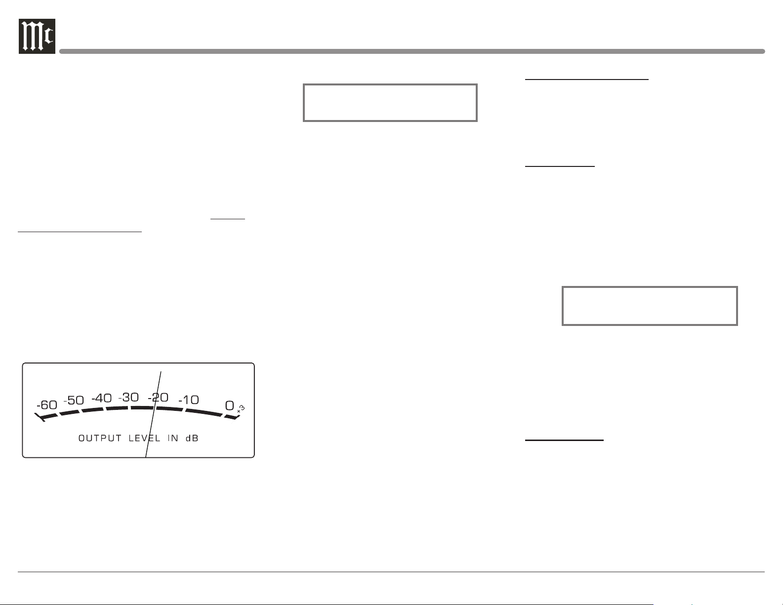
The Remote Control TRIM and LEVEL UP / DOWNPush-buttons may also be used. Approximately 10
seconds after Trim Function Selection and/or adjustments have stopped, the C12000 will switch the Trim
Mode Off.
Adjust
The Front Panel ADJUST Control is used to make
changes to the currently selected TRIM FUNCTION.
HXD
Press the the Front Panel HXD Push-button to activate
or de-activate the HXD Circuitry. Refer to “HEADPHONE HXD SELECTION” on this page for additional information.
Output Meters
The C12000 Preamplifier Output Meters indicate the
Output Level in Decibels (dB) available at the MAIN,
OUTPUT 1 and OUTPUT 2 Connectors/Jacks to drive
Power Amplifiers. Refer to figure 73. The Meters are
calibrated in dB (decibels) and respond to all the peaks
contained in the musical information. A meter reading
of 0dB indicates the unit is delivering its rated output.
Figu re 73
Passthru
The C12000 will automatically turn On and switch to
the previously setup Passthru Input when the McIntosh A/V Processor or Multichannel Surround Decod-
er is turned-on. The Audio Preamplier Front Panel
Alphanumeric Display will indicate “PASSTHRU”.
Refer to gure 74.
Fig u re 74
The Front Panel Controls and Push-buttons are deactived when in the Passthru Mode.
Headphones Jack
Connect a pair of dynamic headphones to the Head-
phones Jack with a 1/4” (0.635cm) stereo phone type
plug for private listening. The default setting is for the
OUTPUT 1 and OUTPUT 2 Power Amplifier Output
Connections to automatically mute, when headphones
are connected to the C12000 Front Panel Jack.
How To Make a Recording
1. Select the desired signal source you wish to record
by using the Front Panel INPUT Control or using the INPUT UP / DOWN Push-button on the
Remote Control.
2. Adjust the record level using the recorder level control and proceed with the recording process.
3. Listen to the playback of the program source just
recorded by selecting the Input Source connected to
the recorder component output.
Reset of Microprocessors
In the unlikely event the controls of the unit stop functioning, the microprocessors can be reset by performing the following:
1. Press and hold in the STANDBY/ON Push-button
until the LED above the STANDBY/ON Pushbutton illumination is extinguished. Then release
the STANDBY/ON Push-button.
2. To switch the C12000 back On press the STANDBY/ON Push-button.
Note: This can be performed with the C12000 On or in
the Standby Mode.
PHONO ADJUSTMENTS
When either the Phono 1 or Phono 2 Input is selected,
the following additional Trim Functions become available when adjusting the TRIM Control. Use the docu-
mentation for your turntable(s) attached to these inputs
to find the best settings and match them accordingly.
RESISTANCE
Change the Resistance Load Setting for a selected
Phono Cartridge (Phono 1 in this example) by performing the following Steps:
1. Select the Phono 1 Input Source.
2. Rotate the Front Panel TRIM Control (TRIM) or
press the t and u Push-buttons on the Remote
Control to select “Phono 1 RES, 47kΩ” as indicated on the Front Panel Information Display. Refer to
figure 75.
Phono 1 RES
47K Ω
Fig u re 75
3. Rotate the ADJUST Control to select desired Resis-
tance. The available settings are: 25Ω, 50Ω, 100Ω,
200Ω, 400Ω, 1KΩ, and 47kΩ.
After approximately 10 seconds the Information
Display returns to indicate the Source Selection and
Settings.
CAPACITANCE
Change the Capacitance Load Setting for a selected
Phono Cartridge (Phono 1 in this example) by performing the following Steps:
1. Select the Phono 1 Input Source.
2. Rotate the Front Panel TRIM Control (TRIM)
or press the t and u Push-buttons on the Remote Control to select “Phono 1 CAP, 100 pF” as
indicated on the Front Panel Information Display.
Refer to figure 76.
28
Page 29
Phono 1 CAP
100 pF
Figure 76
3. Rotate the ADJUST Control to select desired Capacitance. The available settings are: 50pF, 100pF,
150pF, 200pF, 250pF, 300pF, 350pF, and 400pF.
After approximately 10 seconds the Information
Display returns to indicate the Source Selection and
Settings.
GAIN
To change the Amplification Gain Settings from the
default setting for the selected Phono Input, perform
the following Steps:
1. Select the desired PHONO Input Source.
Note: Phono 1 was selected for this example.
2. Rotate the Front Panel TRIM Control (TRIM) or
press the t and u Push-buttons on the Remote
Control to select “Phono 1 GAIN, 46 dB” as
indicated on the Front Panel Information Display.
Refer to figure 77.
Phono 1 GAIN
46 dB
Figu re 77
4. To change the current gain setting, rotate the Front
Panel ADJUST Control or press the p and q
Push-buttons on the Remote Control. The available
settings are 40db, 46db, 52db, 58db, and 64db.
After approximately 10 seconds the Information
Display returns to indicate the Source Selection and
Settings.
PHONO ADJUSTMENTS (Default Settings)
The following are the default settings for each of the
Phono inputs. Phono 1 (PH1) defaults to match common configurations for a Moving Magnet turntable,
while Phono 2 (PH2) defaults to match common
configurations for a Moving Cartridge turnable. Use
the documentation for your turntable(s) attached to
these inputs to find the best settings and match them
accordingly.
Resistance: 47KΩ,(PH1), 1kΩ(PH2)
Capacitance: 100pF (PH1), 50pF (PH2)
Gain: 46dB (PH1), 64dB (PH2)
MAIN OUTPUT (Solid State OR Tube)
Change which circuitry the Main Output uses (Solid
State or Tube). This example assumes the Main Output
is currently set to “Solid State”. Perform the following
steps to change the circuitry to “Tube”.
1. Rotate the Front Panel TRIM Control (TRIM) or
press the t and u Push-buttons on the Remote
Control to select “Main Output, Solid State” as
indicated on the Front Panel Information Display.
Refer to figure 78.
Main Output
Solid State
Figu re 78
2. Rotate the ADJUST Control to change “Solid
State” to “Tube”.
Perform the same steps to change “Tube” to “Solid
State.” After approximately 10 seconds the Information Display returns to indicate the Source Selection
and Settings.
ENABLE OR DISABLE OUTPUTS 1 AND 2
Note: Output 1 (1-SS) uses Solid State amplification,
Output 2 (2-T) uses Tube amplification.
You can turn On or Off the functionality of the Output
1 and 2 push-buttons from the Trim Menu. Perform
the following steps to change Output 1 from On to
Off.
1. Rotate the Front Panel TRIM Control (TRIM) or
press the t and u Push-buttons on the Remote
Control to select “Output 1, On” as indicated on
the Front Panel Information Display. Refer to
figu re 79.
Output 1
On
Figu re 79
2. Rotate the ADJUST Control to change “On” to
“Off ”.
Perform the same steps to change “Off” to “On”.
The same steps can be performed for Output 2. After
approximately 10 seconds the Information Display
returns to indicate the Source Selection and Settings.
ENABLE OR DISABLE TUBE LIGHTS
You can turn On or Off the lights of the Amplifier
Tubes from the Trim Menu. Perform the following
steps to change Tube Lights from On to Off.
1. Rotate the Front Panel TRIM Control (TRIM) or
press the t and u Push-buttons on the Remote
Control to select “Tube Lights, On” as indicated
on the Front Panel Information Display. Refer to
figure 80.
Tube Lights
On
Figu re 80
2. Rotate the ADJUST Control to change “On” to
“Off ”.
Perform the same steps to change “Off” to “On”.
After approximately 10 seconds the Information
Display returns to indicate the Source Selection and
Settings.
29
Page 30

Specications
Frequency Response
+0, -0.5dB from 20Hz to 20,000Hz
+0, -3dB from 10Hz to 100,000Hz
Total Harmonic Distortion
0.005% maximun from 20Hz to 20,000Hz
(High Level Inputs)
0.05% maximun from 20Hz to 20,000Hz
(Phono Inputs)
Rated Output
5V Balanced, 2.5V Unbalanced (Main Outputs)
Maximum Voltage Output
20V RMS Balanced, 10V RMS Unbalanced
Sensitivity (for rated output)
High Level, 450mV Unbalanced, 900mV Balanced
Phono 1 & 2, 0.25mV - 4.5mV
w/ selectable 40-64dB gain
Signal To Noise Ratio (A-Weighted)
High Level - 107dB (Below rated output)
MM Phono - 83dB (Below 5mV input)
MC Phono - 79dB (Below 0.5mV input)
Input Impedance
High Level - 50K ohms Balanced
25K ohms Unbalanced
Maximum Input Signal
High Level, 20V Balanced, 10V Unbalanced
Phono MC, 10mV
Phono MM, 100mV
Volt age G ai n
High Level to Main, Output1 and 2: 15dB
High Level to Rec/Fixed Output: 0dB
Phono MM and MC - Selectable 40dB,
46dB, 52dB, 58dB or 64dB
Output Impedance
200 ohms Balanced
100 ohms Unbalanced
Headphone Load Impedance (Selectable)
16 - 40 ohms, 40 - 150 ohms, 150 - 600 ohms
Headphone Voltage Gain (From Main Output)
16 - 40 ohms, 0dB
40 - 150 ohms, 6dB
150 - 600 ohms, 12dB
Headphone Output
150mW minimum from 16 ohms to 600 ohms load
Power Control and Trigger Output
12VDC, 25mA
Tube Complement
10 Tubes, Six - 12AX7A and Four - 12AT7
(per channel, viewed from top window)
High level - one 12AX7A and two 12AT7
(per channel viewed from Front Panel Window)
Four 12AX7A, two per channel
Power Requirements
Field AC Voltage conversion of the C12000 is not
possible. The C12000 is factory configured for one
of the following AC Voltages:
100 Volts, 50/60Hz at 75 watts
110 Volts, 50/60Hz at 75 watts
120 Volts, 50/60Hz at 75 watts
220 Volts, 50/60Hz at 75 watts
230 Volts, 50/60Hz at 75 watts
240 Volts, 50/60Hz at 75 watts
Standby Power, less than 0.5 watts
Note: Refer to the rear panel of the C12000C Controller
for the correct voltage.
Overall Dimensions
Width is 17-1/2 inches (44.45cm)
Height is 6 inches (15.2cm) including feet
Depth is 19 inches (48.3cm) including the Front Panel,
Knobs and Cables
Weight
C12000 Controller -
27 pounds (12.3 kg) net,
42 pounds (19.5 kg) in shippingcarton
C12000 Preamplifier -
25 pounds (11.3 kg) net,
40 pounds (17.7 kg) in shipping carton
Shipping Carton Dimensions
Width is 27 inches (68.6cm)
Height is 12 inches (30.5cm)
Depth is 25 inches (63.5cm)
30
Page 31
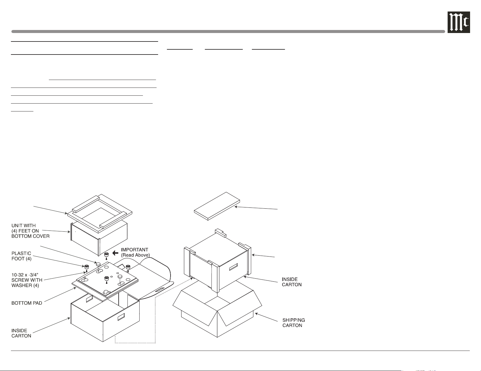
Packing Instructions
FOAM PLUG
In the event it is necessary to repack the equipment for
shipment, the equipment must be packed exactly as
shown below. It is very important that the four plastic
feet are attached to the bottom of the equipment. This
will ensure the proper equipment location on the
bottom pad. Failure to do this will result in shipping
damage.
Use the original shipping carton and interior parts
only if they are all in good serviceable condition.
If a shipping carton or any of the interior part(s)
are needed, please call or write Customer Service
Department of McIntosh Laboratory. Refer to Page 3.
Please see the Part List for the correct part numbers.
Note: The McIntosh C12000 Controller and C12000
Preamplifier use the same shipping carton.
Each unit carton includes separately packaged
accessories.
Top Foam
Pad
Quantity Part Number Description
1 033838 Shipping carton only
2 034669 Side foam pad
1 033836 Inside carton only
1 034414 Top foam pad
1 034576 Bottom pad
4 017937 Plastic foot
4 400159 #10-32 x 3/4” screw
4 404080 #10-7/16” Flat washer
ACCESSORIES
Side Foam Pad
31
Page 32

McIntosh Laboratory, Inc.
2 Chambers Street
Binghamton, NY 13903
www.mcintoshlabs.com
The continuous improvement of its products is the
policy of McIntosh Laboratory Incorporated who
reserve the right to improve design without notice.
Printed in the U.S.A.
McIntosh Part No. 24116100
 Loading...