

Page 1

Fusion 3 Baler & Wrapper
Operator Instructor Manual
Issue 1
McHale
Ballinrobe
Co. Mayo, Ireland
Tel: +353 94 9520300
Fax: +353 94 9520356
Email: [email protected]
Website: www.mchale.net
CLT00485_1
Page 2

This page is intentionally blank
Page 3
McHale Fusion 3 Baler & Wrapper
Thank you for buying this McHale machine, you have chosen wisely!
Given proper care and attention, you can expect it to provide you with
years of dependable service.
Warranty/Guarantee
Attention End User!
Please ensure your machine is fully registered with McHale,
by your dealer, at the time of delivery.
Failure of the dealer to register the machine will render your warranty void!
You can check the registration of your machine by visiting www.mchale.net.
It is important to quote the machine serial number when ordering spare parts or
requesting technical assistance. Space is provided below to record machine details.
See “Description of the serial number plate” on page 30.
Serial number:
Y ear of manufacturer:
Date of delivery:
If you require further copies of this instruction manual,
please quote part number: CLT00485
Due to a policy of continuous product development and improvement, McHale
Engineering reserves the right to alter machine specifications without prior notice and
any obligation to make changes or additions to the equipment previously sold.
Please note that all specifications marked with an in this manual only relate to
certain models or optional equipment. Also these specifications may not be available
in all countries.
It is vital to replace defective parts of the machine immediately and to use only genuine
McHale spare parts, as these are designed and manufactured to the same standard
as the original machine. Spare parts can be obtained from your McHale dealer.
3
Page 4

McHale Fusion 3 Baler & Wrapper
Table of Contents
1 Introduction 8
2 Product Information 9
2.1 Designated use of the machine 9
2.2 Front view 10
2.3 Rear view 11
2.4 General dimensions & specifications 12
2.5 Tractor attachment 12
2.6 Machine specifications 13
2.7 Tyre specifications 13
3 General Safety 14
3.1 Be aware of all safety information 14
3.2 Follow all safety instructions 14
3.3 Store all items carefully 15
3.4 Protective clothing 15
3.5 In case of emergencies 15
3.6 Stay clear of rotating elements 15
3.7 Operating the McHale Fusion 3 15
3.8 In the event of a fire 16
3.9 General safety warnings 16
4 Specific Safety Warnings 20
4.1 Electronic safety warnings 20
4.2 Hydraulic safety warnings 20
4.3 Noise level 21
4.4 Fire precautions 21
4.5 Special safety devices/instructions 21
4.6 Safety instruction decal locations 22
4.7 Safety warnings & instructions explained 23
4.8 Description of the serial number plate 30
4.9 Machine lifting guidelines 31
5 Tractor Requirements & Preparation 32
5.1 Tractor requirements 32
5.2 Control box installation 33
5.3 Attaching to drawbar 33
5.4 Attaching ‘break-away’ brake 33
5.5 Attaching the Fusion 3 to a 540 rpm PTO 34
5.6 Lighting system 34
5.7 Fusion 3 set-up & tractor hydraulic system 34
5.8 Which hydraulic system is used? 36
5.9 Hydraulic spool valve setup 36
5.10 Attaching hydraulic hosing to the tractor 37
5.11 Connecting the control box 38
4
Page 5

McHale Fusion 3 Baler & Wrapper
6 Baler Requirements & Preparation 39
6.1 Net requirements 39
6.2 Care of the net roll 39
6.3 Care of the net wrapping system 40
6.4 Loading & operating the netter system 40
6.5 Net cutter setting 41
6.6 Net tension bar setting 43
6.7 Chopper unit knife removal & installation 43
6.8 Automatic lubrication system 48
6.9 Gear box oil 51
6.10 Tyre inflation pressures 51
6.11 Wheel chocks 52
6.12 Drawbar and PTO shaft stand usage 52
6.13 Drawbar adjustment 54
6.14 PTO Shaft adjustment & maintenance 55
7 Electronic Control System 58
7.1 Control box functions 59
7.2 Control box features 60
7.3 Menu Structure 65
7.4 Warning messages 70
7.5 Simulating a “bale to wrapping” cycle 74
8 Wrapper Operation 75
8.1 Loading plastic film 75
8.2 Plastic film requirements 77
8.3 Wrapping process 78
8.4 Dispenser adjustment 79
8.5 Cut and hold system 79
9 Road Traffic Safety & Operation 82
9.1 Before travelling on any public roadway 82
9.2 Road transportation 83
9.3 Road transportation with side tip attached 83
9.4 ‘Break-away’ brake 84
10 Field Operation & Baler Adjustments 85
10.1 Break-in period 85
10.2 Swath preparation 85
10.3 Pick-up reel height adjustment 86
10.4 Crop guard adjustment 87
10.5 Unblocking system 87
10.6 Chopping system 88
10.7 Selectable knives 88
10.8 Bale density gauge 89
10.9 Setting chamber pre-charge pressure 89
10.10 Chamber door lock 91
10.11 Spare film holders & door latch safety 91
10.12 Adjusting pick-up float springs 92
10.13 Chain adjustments 93
5
Page 6

McHale Fusion 3 Baler & Wrapper
11 Accessories & Optional Equipment 98
11.1 Drawbar hitch options 98
11.2 Stand options 98
11.3 Brake options 99
11.4 Tyre options 99
11.5 Side tip option 99
11.6 Selectable Knives 100
11.7 Crop Roller 100
11.8 Dispenser gear options 101
12 Attachments 102
12.1 Side tip 102
13 Machine Maintenance 105
13.1 Maintenance intervals 105
13.2 Tightening torque values 108
14 Storage 109
14.1 End of season 109
14.2 Start of season 109
15 Trouble Shooting 111
15.1 Trouble shooting overview 111
16 Certification & Warranty 116
16.1 Declaration of Conformity 116
16.2 PDI Form 116
16.3 Change of ownership pre-checks 116
16.4 Limited Warranty 116
6
Page 7

McHale Fusion 3 Baler & Wrapper
This page is intentionally left blank
7
Page 8

McHale Fusion 3 Baler & Wrapper
1
Introduction
The McHale Fusion 3 Baler & Wrapper is a completely new product. This product
combines the baling process with the wrapping process, in one machine. The design
has been developed based on years of extensive research and development in the field
of round bale wrappers and balers. Given proper care and attention, the McHale
Fusion 3 will provide years of reliable and dependable performance.
Please do not assume that you know how to operate and maintain your machine before
reading this manual carefully. In order to prevent misuse, damage and accidents, it is
very important that everybody who will operate the McHale Fusion 3 be a fully trained
operator. They must read and fully understand all of the contents of this manual, before
operating the machine, paying particular attention to the following:
Safety instructions
Functions
Controls (hydraulic & electrical)
It is highly recommended to get acquainted with any new machinery slowly. Take time
to learn and understand all of the features of the machine. Proficiency will increase as
more experience is obtained.
If you have any questions in relation to the instructions in the manual, please contact
your McHale dealer. It is highly recommended that training be sought from your local
McHale dealer.
The operator is solely responsible for the safe use and maintenance of the machinery,
in accordance with this manual. Keep this manual safe and make sure it remains with
the machine, at all times.
8
Page 9

McHale Fusion 3 Baler & Wrapper
2
Product Information
The McHale Fusion 3 is protected against many dangers to itself while being operated
from the control box in both manual and automatic cycles. However, it is of the utmost
importance for the safety of the operator and for others, that the operator pays attention
to all warnings and instructions given in this manual. In particular all safety devices,
decals, guards and controls must be in place and in fully functioning condition. Never
try to clear any malfunction when the tractor is switched on or while the machine is
running. Keep the “Danger Zone” (An area around the machine, detailed in “Danger
zone” on page 16) free of all persons and animals at all times, while the machine is in
operation. This manual must be read and fully understood by anyone who will operate
the machine.
2.1 Designated use of the machine
The McHale Fusion 3 is exclusively designed for normal use in agricultural
applications. The machine has been designed to pick up and compact stalks from the
ground, to produce cylindrical bales of forage, which are in turn wrapped with plastic
stretch film for the purpose of storing as fodder for feeding livestock. This designation
includes the movement of the machine, between fields by track or road, incidental to
the round baler/wrapper’s main use. The manufacturer will not be held responsible for
any loss or damage resulting from machine applications other than those specified
above. Any other use the machine may be put to, is entirely at the owners/operators
risk.
The designated use of the machine includes that:
the operating, maintenance and repair instructions given by the manufacturer
will be strictly fulfilled
exclusively persons who are familiar with it and instructed about the risks are
entitled to operate, maintain and/or repair the machine
the relevant health and safety requirements, that may be in force in the
country of use, will be strictly followed
no other equipment or accessories, other than released by McHale, are
installed in the machine. The use of any other equipment or accessory is
entirely at the owner/operators risk. In such cases, unauthorised
modifications/changes exclude any liability of the manufacturer.
WARNING: Loss of machine validity
By any alteration of safety equipment, the declaration of conformity and
the CE sign loses it’s validity for this machine.
9
Page 10
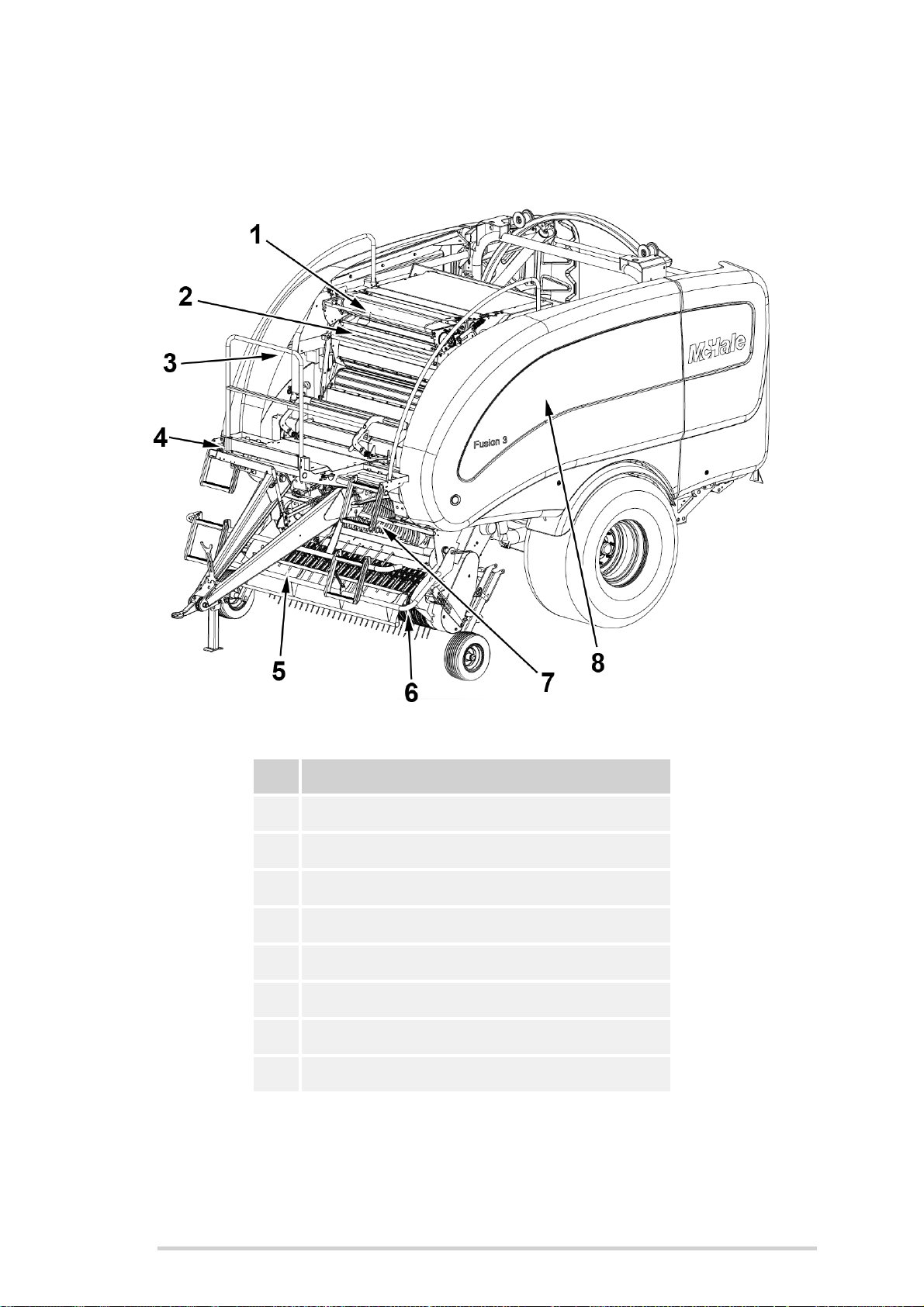
2.2 Front view
McHale Fusion 3 Baler & Wrapper
No. Machine Function
1 Netter unit
2 Net tension bars
3 Hydraulic section (Inside cover)
4 Chamber door pressure clock
5 Crop guard
6 Pick-up reel
7 Chopper unit
8 Wheel chocks & knife blanks (Inside cover)
10
Page 11
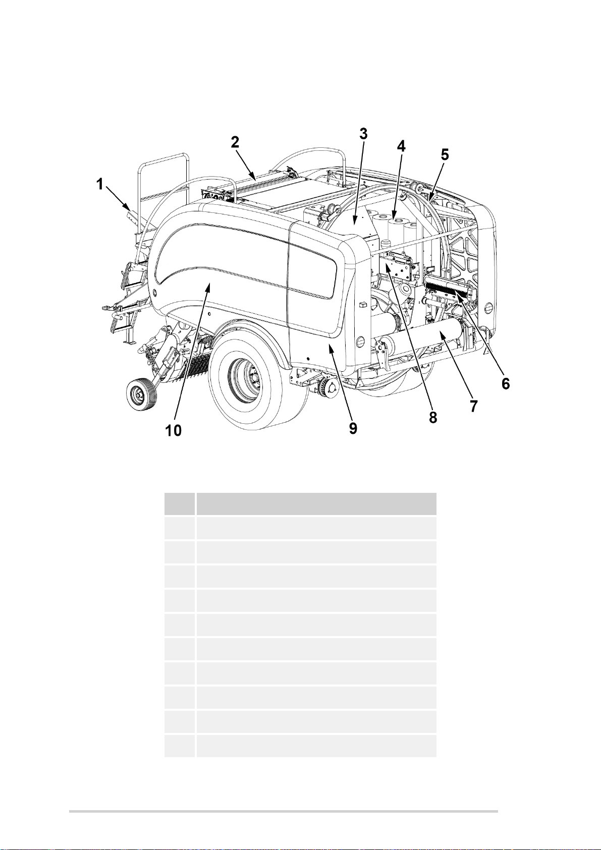
2.3 Rear view
McHale Fusion 3 Baler & Wrapper
No. Machine Function
1 Hose carrier
2 Netter unit
3 Top chamber door
4 Spare film section (Inside cover)
5 Dispenser ring
6 Dispenser
7 Table roller
8 Cut & hold unit
9 Dispenser access door
10 Drive side
11
Page 12

McHale Fusion 3 Baler & Wrapper
2.4 General dimensions & specifications
T ransport length 5.8 m (19’ 1”)
T ranspor t width 2.76 m (9’ 1”)
Transport height 3.02 m (9’ 11”)
T ransport weight 5700 kg (12,566 lbs)
Tyre dimensions 560/60 R22.5
Tyre pressure 1.65 bar/24 P.S.I.
Tyre dimensions (Pick-up reel) 170/60 - 8
Tyre pressure (Pick-up reel) 2.07 bar (30 P.S.I.)
Maximum road speed 40 km/h (25 mph)
Brake system
Check with national road traffic regulations in the individual country!
Hydraulic brakes (Cemagref approved)
Air brakes* (TUV approved)
2.5 Tractor attachment
Drawbar
PTO speed 540 rpm
Lighting 12 V / 7 pin socket
Electrics 12 V / 20 Amp euro socket
Hydraulic systems Load sensing, open centre, closed centre
Minimum pressure 180 bar (2610 P.S.I.)
Minimum flow rate
Low drawbar
High drawbar *
45 l/min (9.9 gal/min) @ 180 bar
(2610 P.S.I.)
(*) May not be available in all countries, check with your McHale dealer for availability
in your country.
Units are given in both metric and UK imperial values, with the latter shown in brackets.
12
Page 13

McHale Fusion 3 Baler & Wrapper
2.6 Machine specifications
Bale chamber diameter 1.25 m (49”)
Bale chamber width 1.23 m (48”)
Pick-up width 2.00 m (78”)
Net width Max. 1.26 m (49.5”)
Net tying
Net length
Film width 750 mm (29½”)
Film stretch 70% (55% optional)
Plastic film
Dispenser rotary speed Max. 30 rpm
Film layers 2+2; 2+2+2; etc.
Film storage
2000 m / Max 4000 m
(2187 yd / Max 4374 yd)
8 Rolls (+ 2 Rolls on
dispenser)
2.7 Tyre specifications
Tyre type Pressure
560/60 R22.5 1.65 bar (24 P.S.I.)
650/50 R22.5 (Optional Specification) 1.65 bar (24 P.S.I.)
170/60 - 8 (Pick-up tyre) 2.07 bar (30 P.S.I.)
13
Page 14
McHale Fusion 3 Baler & Wrapper
3
General Safety
3.1 Be aware of all safety information
Follow all safety precautions and practice safe operation of machinery, at all times.
Warning, caution, information & environmental messages:
When reading this manual, pay particular attention when you see the symbols below
i.e. Warning, Caution, Information & Environmental. They will be used at various points
in this manual and may also appear on safety decals on the machine. The purpose of
these messages is to ensure that the most important information stands out from the
rest of the text.
WARNING: This symbol indicates a potentially hazardous situation,
that if not avoided could result in machinery damage, personal injury
or even death.
CAUTION: This symbol indicates a potentially hazardous situation,
that if not avoided could result in machinery damage or personal
injury.
INFORMATION: This symbol is used to identify special instructions
or procedures which, if not followed strictly, could result in
machinery damage.
ENVIRONMENTAL: This symbol reminds you to respect the
environment in relation to the correct disposal of waste material.
3.2 Follow all safety instructions
Using this manual, read all safety instructions and messages, and
be aware of the meanings of all safety decals. If safety decals are
damaged or missing due to wear and tear or component
replacement, ensure that they are replaced. Refer to section 4.7 in
this manual (or spare parts book provided) to see the spare part
codes for the relevant decals, which are available from your McHale
dealer.
14
Page 15
McHale Fusion 3 Baler & Wrapper
As with all machinery, learn all operations and use controls by reading this manual
thoroughly. Do not attempt to let anyone operate this machine without being fully
instructed.
3.3 Store all items carefully
Store all attachments such as spare net rolls, films rolls and any
other stored items in a secure and safe manner so as to prevent
items from falling. Keep storage areas clear of bystanders and
children.
3.4 Protective clothing
Always wear clothing and safety equipment that is fit for the job at
hand, never wear loose clothing. In the event of loud noises, wear
suitable protective hearing devices. Use of mobile phones or radio/
music headphones are not recommended while operating
machinery as these impair the operators attention.
3.5 In case of emergencies
In the event of any accident, emergency equipment should be kept
close at hand. A first aid kit and fire extinguisher along with
emergency phone numbers should always be available to machine
operators.
3.6 Stay clear of rotating elements
Serious injury or death can result from entanglement of clothing or body parts with PTO
shafts, drivelines and other rotating and moving components.
Keep all guards in place at all times, only wear close fitting clothing, and ensure that
tractor engine has stopped, key removed and that PTO has stopped turning before
carrying out any adjustments, connections or cleaning of PTO driven equipment.
3.7 Operating the McHale Fusion 3
In order to avoid serious injury or even death by being pulled into the machine:
Never attempt to feed net or crop into the baling chamber or attempt to unplug
pick-up area while the baler is running.
Disengage the PTO, apply handbrake, shut the tractor engine off and remove
the key from the ignition.
Stand well clear of the baler and tractor when the machine is operating.
15
Page 16
McHale Fusion 3 Baler & Wrapper
3.8 In the event of a fire
In the event of a fire, the following is given only as a guideline
procedure as it is the operator’s decision to ascertain the
seriousness and hence the solution to the situation.
1. Switch control box to manual mode (See “Electronic Control System” on
page 58). Immediately tip bale off rear roller and leave roller in tipped position.
2. Eject the bale from the baling chamber by opening the chamber doors.
3. Move the tractor and baler away from the flammable material.
4. Disengage the PTO, turn off the tractor and remove the key from the ignition.
5. Remove all hosing and electrical looms from the machine.
6. With all connections removed, disengage the drawbar from the tractor.
7. Drive the tractor away from the baler.
8. Using a suitable fire extinguisher, put out all the fires.
WARNING: Fire prevention
It is recommended that the baler be kept reasonably clean and free of
build-ups of grass, lubricants, etc. This will help to reduce the risk of fires.
3.9 General safety warnings
Read and understand this operator manual before using the machine. If any of the
instructions appear unclear do not hesitate to contact your McHale dealer.
Only competent persons who have read and fully understood this manual are qualified
to operate this machine. The owner of this machine is obliged, by law, to ensure that
every operator understands all of the functions, controls, working processes and safety
warnings, before operating the machine.
Safety devices
All safety devices such as guards, protection parts and safety controls must
be in place and in fully functioning condition. It is forbidden to operate this
machine with defective or incomplete safety devices.
Danger zone
The ‘Danger Zone’ is the area around the rotating dispensers (approx. 2
metres radius from the rotating centre axis) & (a minimum of 5 metres) at the
back of the machine to allow for safe bale discharge.
NOTE: “Danger Zone” can vary in size
The operator must be aware of the ‘Danger Zone’ which can vary in size,
depending on operating conditions, i.e. hilly terrain.
16
Page 17

McHale Fusion 3 Baler & Wrapper
It is the operator’s responsibility to ensure that there is no person in the
‘Danger Zone’ while operating the machine, especially during start up.
Before repair or reassembly
Safe lifting gear of sufficient capacity must be used for machine assembly. All
chains and slings used must be in good condition.
Before operation
The operator must ensure that the manufacturer’s instructions for attaching
and detaching the machine are followed. This includes the drawbar
attachment, the electric and hydraulic lines, in particular the lighting and brake
system.
The operator must ensure that all covers are closed and all safety devices are
in operating mode.
The operator must ensure that there is no person in the ‘Danger Zone’.
Always be familiar with the health and safety requirements that may be in
force in the country of use.
During Operation
While operating this machine on hilly or sloping ground the operator must take
extra precautions, in particular the ‘Danger Zone’ is increased in such
conditions as bales are more likely to roll away, causing a potential risk.
The operator must ensure that there is a minimum of 4 m clearance between
the machine and any obstacle above, in particular electrical high voltage lines.
Never operate the machine with dispenser safety arms damaged or missing.
Be careful when working with the cut and hold. Remember that the
accumulators are under pressure.
Avoid contact with the knife.
Do not attempt to clamp plastic film in the cut and hold mechanism.
Particular care must be taken, if the machine is left idle for any extended
period, to ensure that all sensors and safety features are working correctly.
WARNING: Do not carry people or animals on the machine
The operator must ensure that no persons or animals are carried on the
machine at any time or are hidden under the machine (on the tractor
persons are only allowed to sit on the relevant seats).
17
Page 18

McHale Fusion 3 Baler & Wrapper
Before travelling on public roads
The owner of this machine is obliged by law to ensure that every operator has
a valid driving licence and is familiar with the road traffic regulations relating to
the country of use.
Always ensure that the electronic control box and oil supply are switched off.
Always attach the dispenser safety chain.
When parking, both wheels of this machine have to be blocked using the
wheel chocks and hand brake (if fitted) should be applied according to the
road traffic regulations, relating to the country of use.
Performing maintenance
Maintenance and repair work on the Fusion 3 should always be carried out in
accordance with this manual.
Maintenance and repair work exceeding the content of this manual should
only be carried out by qualified persons or your McHale dealer.
When conducting maintenance work tie long hair behind your head. Do not
wear a necktie, necklace, scarf or loose clothing when you work near the
machine or moving parts. If these items were to get caught, severe injury
could result.
Before working on this machine, such as replacing net/film rolls, clearing
forage away from any part of the machine, or altering any setting, the operator
must ensure the following:
(a) The tractor has definitely stopped moving
(b) The hand brake is applied
(c) The engine is shut down
(d) The ignition key is removed
(e) PTO shaft is removed from PTO stub
(f) Electronic power supply and control box is disconnected
(g) Hydraulic oil supply is switched off
* It is forbidden to open any safety guards or to carry out any work on the machine, unless
the above specified precautions have been carried out.
When conducting maintenance work always support the machine properly.
Where possible, lower the attachment or implement to the ground before you
work on the machine. If it is not possible to lower the machine or attachment
to the ground, always securely support the machine or attachment. Do not
work under a machine that is solely supported by a jack. Never support the
machine with props that may break or crumble under continuous load.
Never disable any electrical safety circuits, tamper with safety devices or carry
out any unauthorised modification to the machine.
Avoid heating near pressurised fluid lines, as pressurised lines can be
accidentally damaged when heat goes beyond the immediate flame area.
18
Page 19

McHale Fusion 3 Baler & Wrapper
During inspection
If carrying out an inspection during machine operation within the ‘Danger
Zone’ (highly dangerous and NOT recommended!), then there should be a
fully trained and competent second person operating both the tractor and
baler controls. If at any time the second operator loses sight of the inspector,
turn off all tractor power immediately! Such inspection should only be carried
out if all guards are fully in place, the machine is on level ground and a safe
distance is kept from any hazards on the machine i.e. pick-up region.
19
Page 20

McHale Fusion 3 Baler & Wrapper
4
Specific Safety Warnings
4.1 Electronic safety warnings
This machine is equipped with electronic parts and components which comply
to the EMC directive 2004/108/CE but still may be influenced by
electromagnetic transmissions of other apparatus, such as welding machines,
etc.
Check electric cables regularly for signs of breakage or wear. If in doubt
always replace (faulty safety circuits will cause risks).
Do not modify any safety circuits.
4.2 Hydraulic safety warnings
The maximum pressure in the hydraulic system of this machine should not
exceed 210 bar.
Always ensure the system is not under pressure before working on the
machine. Oil under pressure can penetrate the skin and cause injury. Beware
of pipes under accumulator pressure, depressurise lines by unthreading
connections extremely slowly.
Hydraulically actuated devices, such as pick-up, cutting device and wrapping
ring, must be blocked mechanically against movement, before working on the
machine.
If any hoses are removed or replaced ensure they are marked and re-installed
to the correct position during re-assembly.
Check hoses regularly for signs of leakage or wear. If in doubt always replace.
The recommended maximum working time of hoses should not exceed 5
years. Only use exact specification McHale genuine replacement parts.
Do not work on hydraulic systems unless you are qualified to do so. This work
should only be carried out by qualified persons or your McHale dealer.
20
Page 21

McHale Fusion 3 Baler & Wrapper
4.3 Noise level
The European Regulation 86/188/EEC directs employers and employees to
control the noise level at work. The noise level at field work may differ
according to the tractor, ground, crops and other environmental conditions.
In normal conditions, whilst driving the McHale Fusion 3, the noise level to
the driver’s ear does not exceed 70 dB (A) with the rear screen of the tractor
cabin open. The common noise level of the machine and the tractor is
primarily influenced by the tractor noise (radio is an additional noise source). It
is recommended to operate this machine with closed cabin windows.
4.4 Fire precautions
Be aware that crops are easily inflammable.
Do not smoke or make use of any open fire next to the machine.
A functioning fire extinguisher should always be available on the tractor.
The machine is to be kept clear of oil, grease, crops, string, plastic or any
other flammable material at all times.
Do not continue to work with overheated parts, cables or pipes, unless you
have identified and eliminated the reason for overheating.
4.5 Special safety devices/instructions
According to European safety regulation, the covers of this machine are
designed to be opened only by the aid of a special tool and to be closed
without a tool. To unlock the covers, the locks should be turned slightly anticlockwise with a 13 mm spanner or flat blade screwdriver. To lock the covers
push the cover towards the chassis until the fasteners lock into place. It is
forbidden to operate the machine without the covers or with them open. The
owner of the machine is obliged, by law, to ensure that all covers are inst alled
on the machine and are in good functioning condition.
When maintenance or repair work has to be carried out at the open bale
chamber, the additional upper chamber lever valve must be in the locked
position. Before the upper chamber can be closed it has to be unlocked again.
Before replacing the knives of the chopping system, make sure that all knives
are in the ‘UP’ position. Always use protective gloves when working at the
chopping system.
Avoid contact with the plastic film cutting knives.
21
Page 22

McHale Fusion 3 Baler & Wrapper
4.6 Safety instruction decal locations
Figure 4.a - Decals on the front of the Fusion 3
22
Figure 4.b - Decals on the rear of the Fusion 3
Page 23

McHale Fusion 3 Baler & Wrapper
4.7 Safety warnings & instructions explained
Danger areas which cannot be protected by any devices are marked by yellow safety
decals. Therefore it has to be ensured that all safety warnings and instructions are
understood and followed. If any of the decals are damaged or missing, they are
available from your McHale dealer. The relevant part numbers are shown in brackets.
The decals featured on the McHale Fusion 3 are displayed with their meanings below:
Free flow return to tank
(CST00006)
Danger of rotating parts, foreign objects
Keep clear of machine while working
(CST00014)
Keep hands clear of rotation roller
(CTS00017)
Keep hands out of crush area
(CST00019)
Check wheel nuts daily
(CST00020)
23
Page 24
McHale Fusion 3 Baler & Wrapper
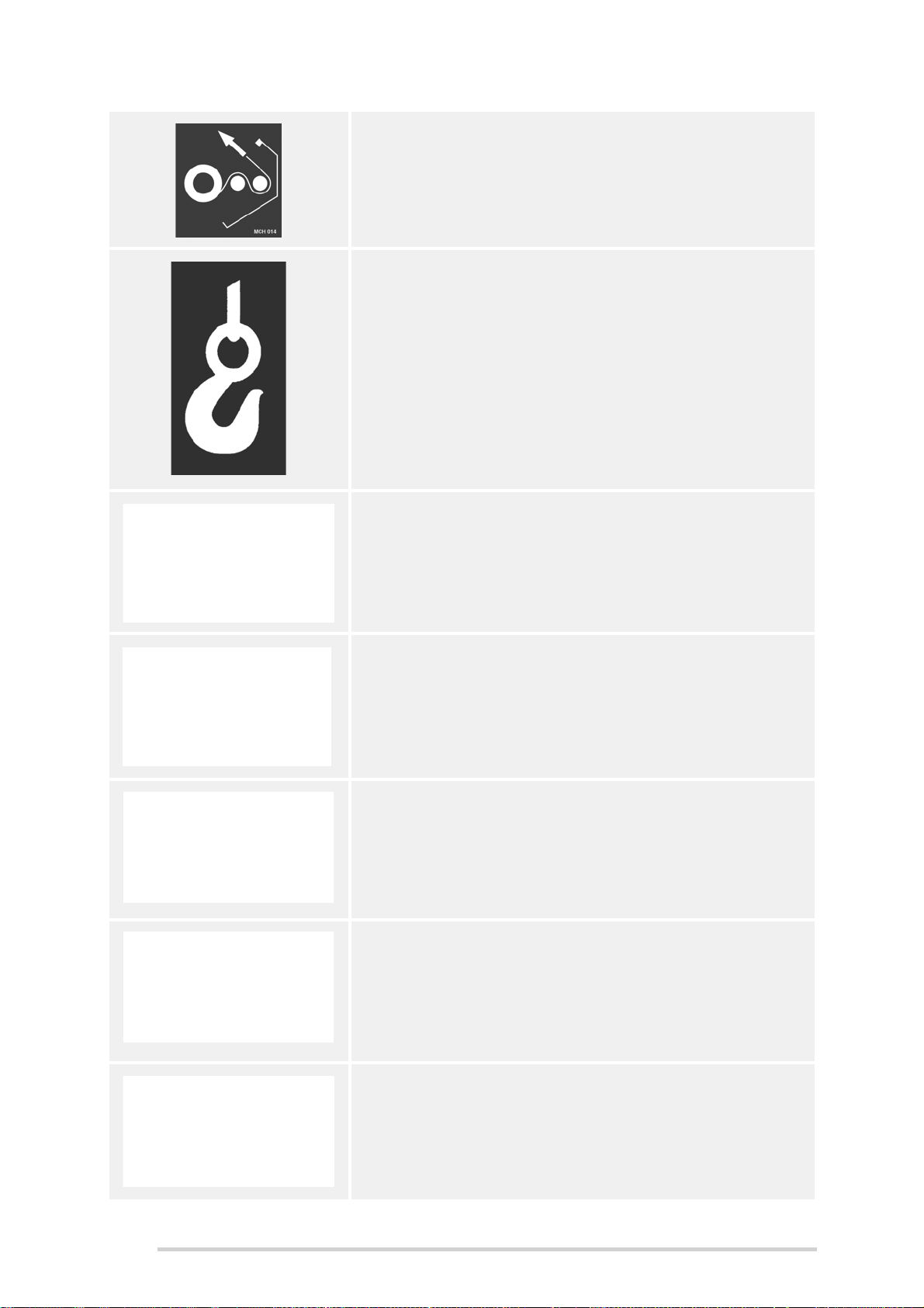
Diagram of plastic film path through dispenser
(CST00022)
Lifting hook location
(CST00032)
Do not dismantle
High pressure always
(CST00056)
Grease daily
(CST00060)
Do not stand on the platform or elsewhere on the
machine when the machine is moving or working
(CST00107)
Keep clear of pickup area as long as the engine is
running and the PTO shaft is connected to the tractor
(CST00108)
24
Read instruction manual before use
(CST00110)
Page 25

McHale Fusion 3 Baler & Wrapper
Beware of high-pressure hoses, even when the
machine is switched off
Also, read and understand manual before working on
any part of the hydraulic system
(CST00111)
Knives of the cutting device should only be removed
with an appropriate tool and protective gloves
(CST00112)
Turn off and remove key from tractor
Read and understand the manual before working on or
performing maintenance on the machine
(CST00113)
Close protective covers before operating the machine
(CST00114)
Hydraulic accumulator is under high pressure
Slowly release hydraulic pressure before carrying out
any maintenance
(CST00115)
Beware of rotating dispensers, ring and moving
wrapping table rollers
(CST000116)
Knife release lever:
horizontal position-locked
vertical position-unlocked
(CST00118)
25
Page 26
McHale Fusion 3 Baler & Wrapper
Keep hands out of the crush area between the roller
and chassis rail
(CST00120)
Maximum hydraulic pressure and maximum PTO
speed. This machine must not be connected to
hydraulic systems with pressure higher than 210 bar
(CST00121)
Stay clear of rotating PTO shaft. Never use the
machine if the PTO guard is missing or damaged.
Entanglement in the rotating drive line can cause
serious injury or death. It is important to ensure that
the rotating guard on the drive line rotates freely.
Always stop the engine and ensure the driveline has
stopped before making connections, adjustments or
cleaning out PTO driven equipment.
(CST00132)
General warnings
(CST00134)
Disconnect the Fusion 3 feed line and turn off the
control box during road use. Read the operation
instruction manual before proceeding.
(CST00135)
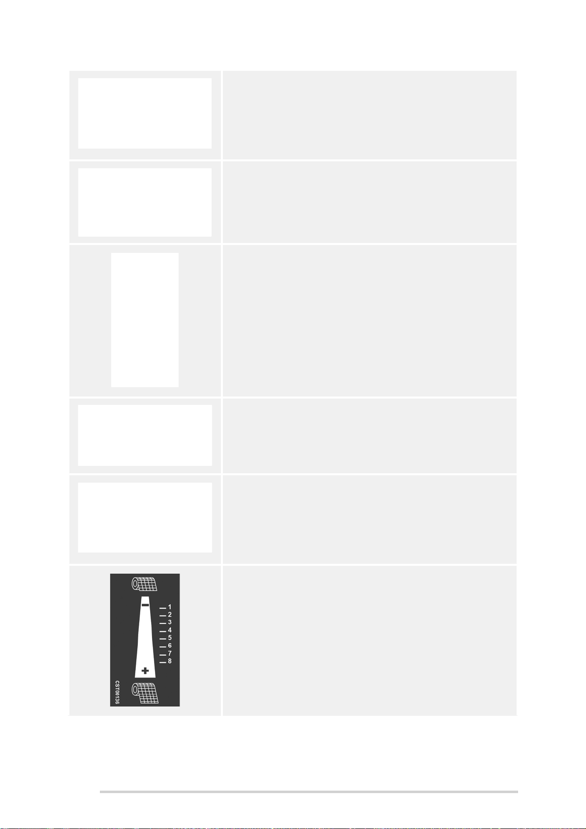
Net amount setting decal
(CST00136)
26
Page 27

McHale Fusion 3 Baler & Wrapper
Dispenser park rotation decal
(CST00137)
Side Tip: Not for road use
(Placed on side tip only)
(CST00138)
Do not stand in the articulation area while the tractor
engine is running.
(CST00141)
Never perform any adjustments or reach into the netter
unless the PTO has been disengaged and the tractor
has been shut down and the key has been removed. It
is also recommended that the tension be released
from the netter knife to avoid it being tripped
accidentally.
(CST00142)
Stay clear of the rotating PTO shaft. Never use the
machine if the PTO guarding is missing or damaged.
Entanglement in rotating drive line can cause serious
injury or death. It is important to ensure that the
rotating guard on the driveline rotates freely. Always
stop the engine and ensure that driveline has stopped
before making connections, adjustments or cleaning
out PTO driven equipment.
(CST00143)
27
Page 28
McHale Fusion 3 Baler & Wrapper
Crush hazard. Keep hands clear of rotating elements.
Do not remove the guard while the engine is running.
(CST00144)
Disconnect the power supply to the control box and
turn off the tractor before commencing work on the
electrical system or welding on the machine.
(CST00145)
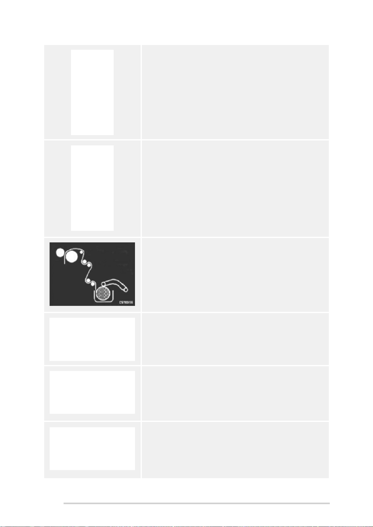
Diagram of net path through feeding rollers
(CST00156)
Ensure tyre pressure is at 1.65 BAR (24 P.S.I.)
pressure and torque nuts to 220Nm.
(CST00157)
Free rotating transfer roller
Do not step on this roller!
(CST00161)
Free rotating transfer roller
Do not step on this roller!
(CST00162)
28
Page 29

McHale Fusion 3 Baler & Wrapper
Ensure area around brakes is clear of dry material
(CST00163)
Float decal. Indicating that during operation of the
baler, the control lever of the spool operating the pickup reel should be in the float position.
(CST00609)
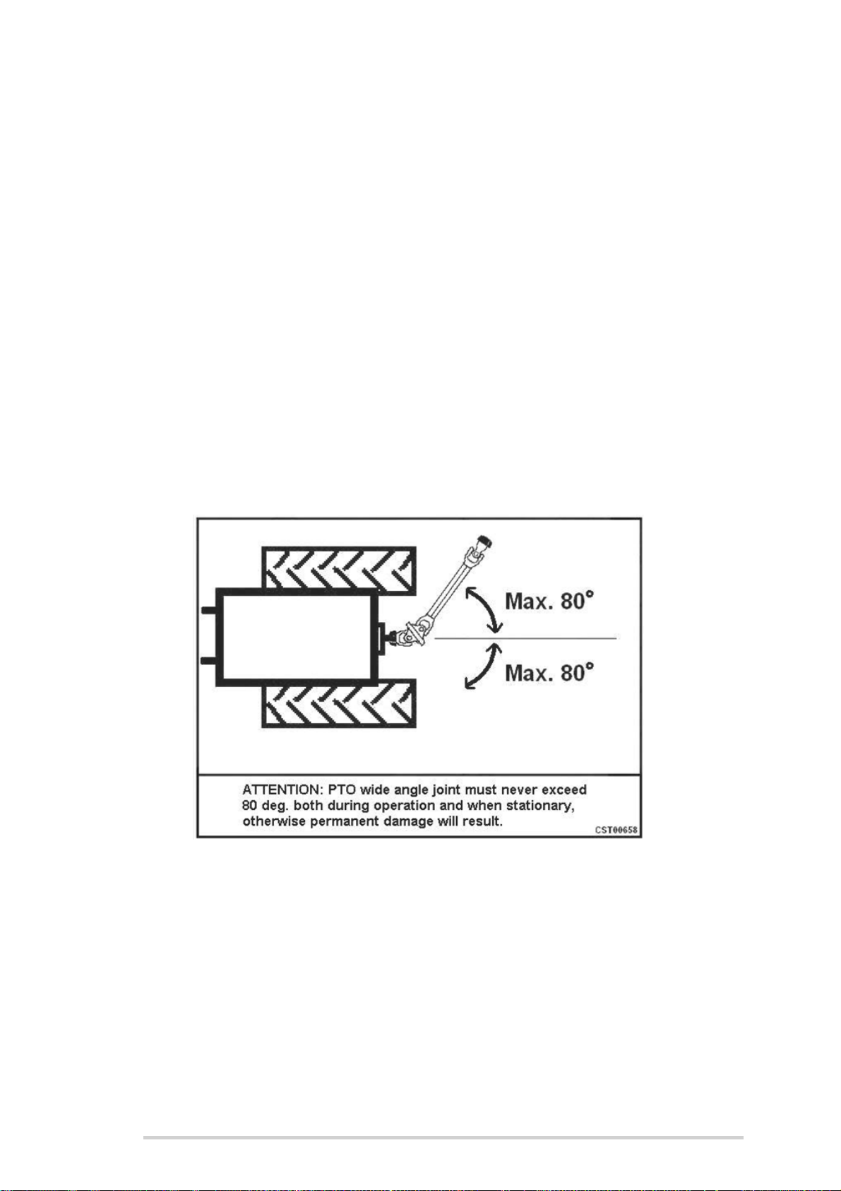
The PTO wide angle joint must never exceed 80
degrees, both when stationary or during operation.
Permanent damage may result otherwise.
(CST00658)
Wheel direction
(CST00711)
Keep hands out of crush area
(CST00753)
Keep hands out of crush area
(CST00754)
Lock the chamber door before working on the open
bale-forming chamber
(CST00756)
29
Page 30

McHale Fusion 3 Baler & Wrapper
4.8 Description of the serial number plate
The following is a description of the serial plate meanings:
a. Serial number of the machine
b. Year of manufacture of the machine
c. Model name/Number of the machine
d. Maximum vertical drawbar load (Newton’s)
e. Maximum horizontal drawbar load (Newton’s)
f. Maximum road speed (kilometres per hour)
g. Maximum gross weight at 10 kilometres per hour
h. Net weight of the machine
i. Maximum axle load at maximum road speed of 40 kilometres per hour
j. Vehicle width: with standard size tyres / optional specification tyres
k. Vehicle height (metres)
l. Vehicle length (metres) with no rear attachments / with side tip attachment
30
Page 31
McHale Fusion 3 Baler & Wrapper
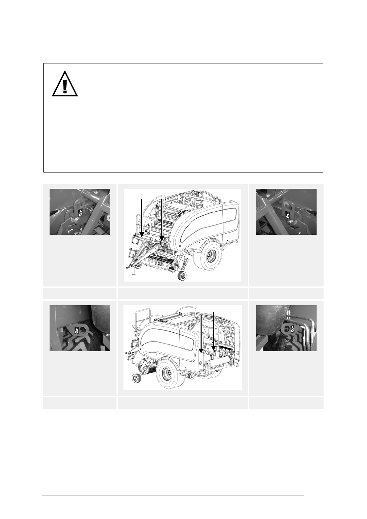
4.9 Machine lifting guidelines
WARNING: Machine Lifting
Only use chains or strapping that are rated for a minimum load
of two tonnes (2,000 kg) per chain or strap when using the four
lift eye locations on the chassis, shown below
The crane or lifting device must be capable of lifting a
minimum load of seven tonnes (7,000 kg)
Never go under a suspended machine or attempt to try and
stop it if moving erratically, death or serious injury may result
Always be observant of people and objects around the
suspended machine and do not allow the machine to impact
heavily on the ground after suspension or movement
RHS lift hook Front Left View LHS lift hook
RHS lift hook Rear Right View LHS lift hook
31
Page 32
McHale Fusion 3 Baler & Wrapper
5
Tractor Requirements & Preparation
5.1 Tractor requirements
The minimum recommended size of tractor for operating the McHale Fusion 3
comfortably depends mainly on the crop condition and the required cut length of the
forage. On flat ground McHale recommends a tractor size of approximately 85 kw. On
hilly ground or difficult conditions, an additional 10 to 15 kw is advisable.
Ideally the tractor should have a load sensing hydraulic system, as the McHale
Fusion 3 works at it’s best in this setup. Please refer to “Fusion 3 set-up & tractor
hydraulic system” on page 34 and “Which hydraulic system is used?” on page 36 for
correct selection of hydraulic setup.
NOTE: Use good quality oil
Ensure that the tractor has clean, good quality oil, hydraulic/universal oil
to avoid problems later on. Also, the hydraulic filters on the tractor should
be changed regularly, according to the manufacturers service
instructions. Avoid dirt getting into the hydraulic couplings.
The following items on the tractor are required for attachment of the baler wrapper
combination behind the tractor:
1. Low/high drawbar hitch* that is suitable for an imposed load of minimum
6000 kgs
2. One ½” - female quick release single acting, with “float position” for pickup reel.
3. One ¾” - female quick release for hydraulic power supply of minimum 45 litres
per min @ 180 bar
4. One ¾” - male quick release for return line (Must be free flow to tank)
5. One ⅜” - female quick release for load sensing (Only required if tractor has a
load-sensing hydraulic system)
6. One 12 V / 7 pin socket for lighting
7. One 12 V / 20 Amp euro socket or battery power cable
8. One hydraulic brake coupling or two air brake couplings
9. A 1 ⅜”, 6 spline PTO shaft (set to a speed of 540 rpm)
10. One secure attaching point to tie the ‘break-away-brake’ rope to the tractor
* Depending on country of use
32
Page 33
McHale Fusion 3 Baler & Wrapper
5.2 Control box installation
The electronic control box must be located inside the tractor cab in the operator’s field
of vision and within easy reach of the red emergency stop button. It is secured to the
glass using the suction pad on the rear. Ensure that the cable to the machine is not
under tension and not near sharp edges, etc. The electric power supply is obtained
from the euro socket of the tractor.
Connect the supplied fused electric power lead to the tractor battery ensuring to route
away from sharp edges and hot surfaces. The control box is not waterproof, it must be
protected from rain. See “Electronic Control System” on page 58.
CAUTION: Electrical Power Supply
Do not use any other electric power supply for the electronic control
system, otherwise damage may occur.
5.3 Attaching to drawbar
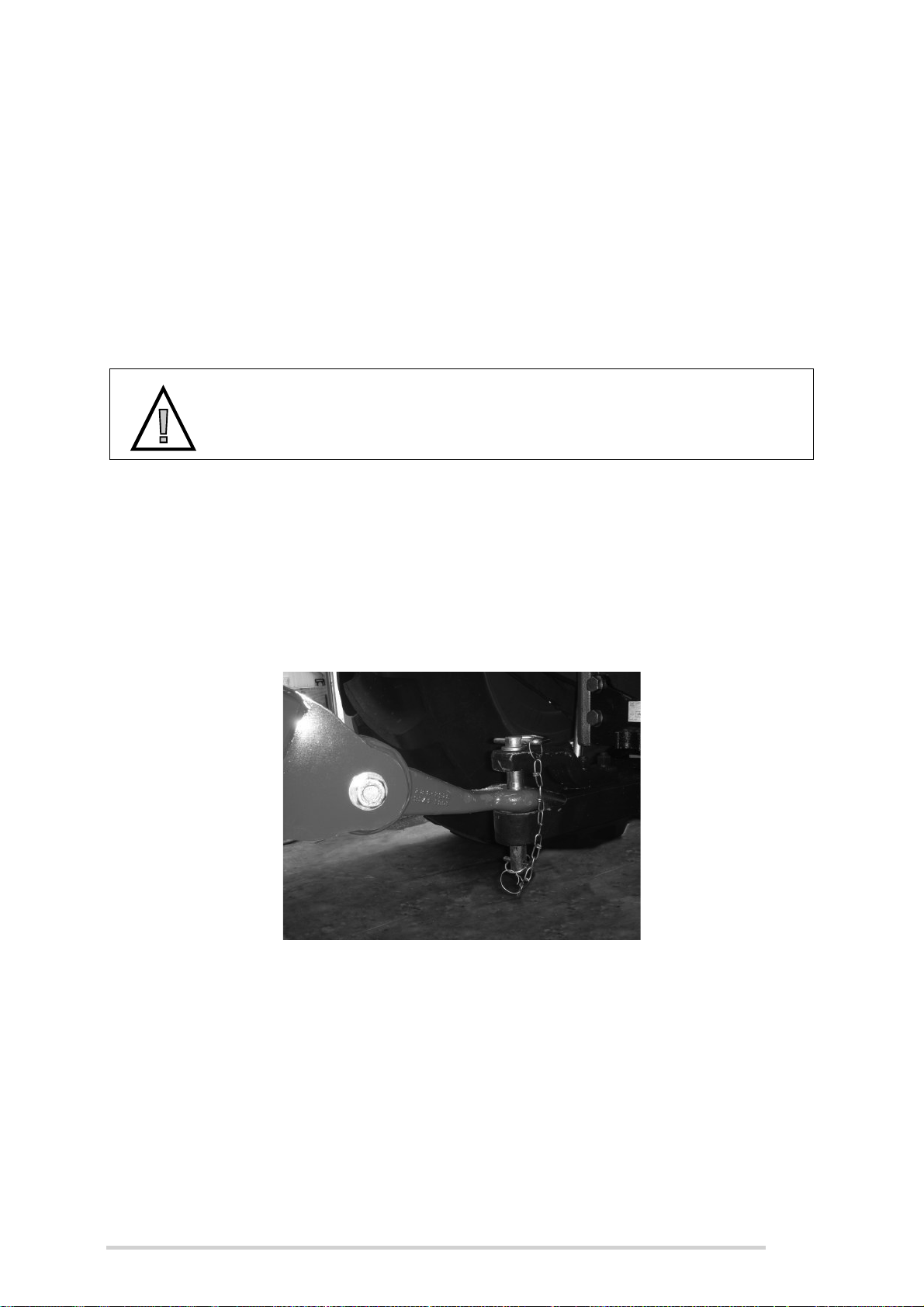
The drawbar is to be attached so that the McHale Fusion 3 is horizontal to the ground
as in “Drawbar adjustment” on page 54. Machines are set up for hitching to the tractor
drawbar as shown in Figure 5.a below. Once the tractor is attached to the drawbar,
attach the PTO shaft. Depending on the country of use a safety chain may also be
required. Detach in reverse order of attachment.
Figure 5.a - Drawbar attachment
5.4 Attaching ‘break-away’ brake
The McHale Fusion 3 is fitted with a hand brake which must be applied when the
machine is detached from the tractor. The hand brake handle has a rope fitted to a
calibrated ring which must have the other end securely fixed to the tractor each time
the Fusion 3 is attached to the tractor. Should the Fusion 3 hitch ever become
detached from the tractor, this rope will apply the brakes on the Fusion 3.
33
Page 34
McHale Fusion 3 Baler & Wrapper
CAUTION: Release hand brake
Always ensure the hand brake has been released before moving the
Fusion 3 on the road or operating in a field.
5.5 Attaching the Fusion 3 to a 540 rpm PTO
All mechanical functions are related to the correct PTO speed. Follow the instructions
as supplied with the PTO unit for correct assembling of the PTO shaft to the tractor
(See “PTO Shaft adjustment & maintenance” on page 55). Ensure PTO cover-guards
are prevented from rotating, by securing the chain to the tractor.
CAUTION: Standard PTO of 540 rpm, maximum = 610 rpm
The McHale Fusion 3 should be driven with a standard PTO speed of
540 rpm. The maximum PTO speed allowed = 610 rpm. A PTO speed
above 610 rpm is likely to cause damage to machine components. Do
not use any faster PTO speed other than specified above!
5.6 Lighting system
The 7 pin plug of the lighting system on the machine must be connected to the 7 pin
socket on the tractor.
NOTE: Check lighting system before travelling on the road
Before travelling on a public road, the operator must ensure that the
complete (tractor and machine) lighting system is in a fully functioning
condition.
5.7 Fusion 3 set-up & tractor hydraulic system
CAUTION: Hydraulic System Setup
It is very important to determine the correct hydraulic system on the
tractor, as a wrong set-up will cause serious damage to the tractor
hydraulic system, or at least excessive heating of the oil.
There are 3 systems found on tractors, as outlined below:
1. Open Centre: This is the most common system on smaller tractors (less than
60kw) and also on some bigger older tractors. In this system, all the oil flows
through the control valve, when the machine is idle. The tractor will have a fixed
displacement pump and the output flow will be max. 60 litres/min and flow is
usually not adjustable.
2. Closed Centre: Although not so common on today’s tractors, this system is
still found on the older John Deere models (pre. 00 & 10 series), but also on
some other makes and particular models. In this system, no oil flows through
the control valve, when the machine is idle, but maintains max. oil pressure in
34
Page 35

McHale Fusion 3 Baler & Wrapper
the feed line. The tractor will have a fixed displacement pump and the output
flow is usually not adjustable.
3. Load-Sensing with “Power Beyond” fitted: This is, by far, the preferred
system. Most newer tractors are done this way, but not all. In this system, no
oil flows through the control valve, when the machine is idle, but it maintains a
low oil pressure in the feed line, (approx. 21 bar). The tractor will have a
variable displacement pump and will always have some means of adjusting the
oil flow on each auxiliary valve.
In it’s most ideal configuration, the tractor will have a “Power Beyond” connection, i.e.
oil comes direct from the pump, by-passing the tractor auxiliary valves, to a “Female ¾”
Quick Release’ connection, which becomes the Fusion 3 feed.
rd
It will also have a 3
connection to the tractor, called the pilot sensing line, and this pipe
sets the correct oil flow for the tractor to pump for each operation.
This is the most advanced and efficient hydraulic system available, as the Fusion 3
control valve now controls the amount & pressure of oil required for each control valve
operation, and only the correct amount is pumped. This will save up to 20 kw PTO
power on the tractor.
Although it is possible to operate the Fusion 3 with a load-sensing system via the
tractor auxiliary spools, i.e. continuous oil flow (control valve is set to open centre setup and flow is set to 45 litres/min from the tractor). McHale do not recommend
operating the Fusion 3 in this set-up, as controlling the oil flow is too variable from one
tractor to another, and there is also a 20 kw PTO power loss with it’s associated overheating of the oil.
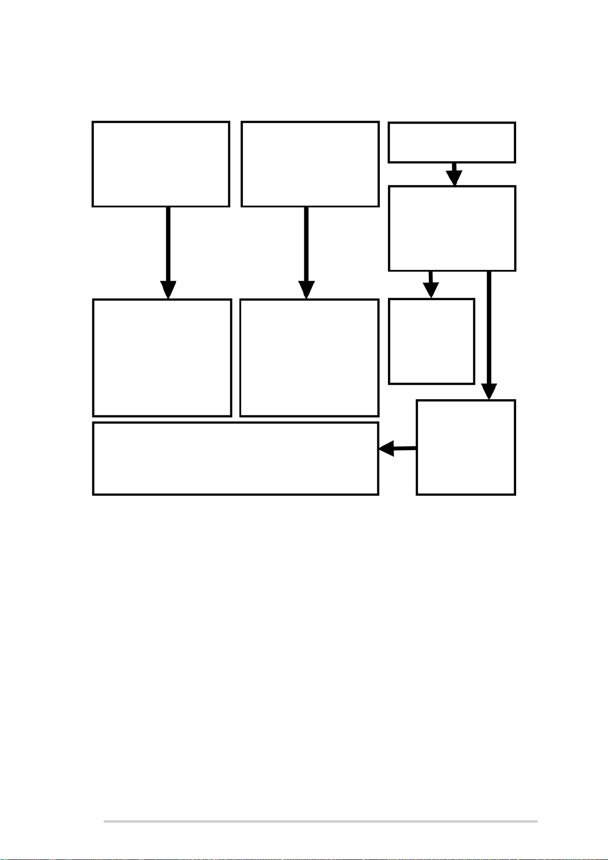
Once the correct tractor system is identified, use the map in the next section, to select
the best set-up for the Fusion 3.
35
Page 36
McHale Fusion 3 Baler & Wrapper
1. Open Centre
Set as Open Centre
(default factory setting,
as shown in section 5.9)
2. Closed Centre
Set as Closed/Load
Sensing (as shown in
Section 5.9)
3. Load-Sensing
Does the tractor have a
“Power Beyond” &
“Sensing Line”
connection fitted?
Yes
No
Contact your
tractor dealer
to get “Power
Beyond”
option fitted
Set as closed/
load sensing
(as shown in
Section 5.9)
SET-UP (A)
1. Plug feed-line into
auxiliary spool output
ensuring it can supply an
oil flow of at least 45 litres/
min @180 bar.
2. Plug return-line into
free-flow return.
SET-UP (B)
1. Plug feed-line into
auxiliary spool output
ensuring it can supply an
oil flow of at least 45
litres/min @180 bar.
2. Plug return-line into
free-flow return.
SET-UP (C)
1. Plug feed-line into power beyond output
2. Plug return-line into free-flow return
3. Plug sensing-line hose into “Power Beyond”
connection on tractor
5.8 Which hydraulic system is used?
5.9 Hydraulic spool valve setup
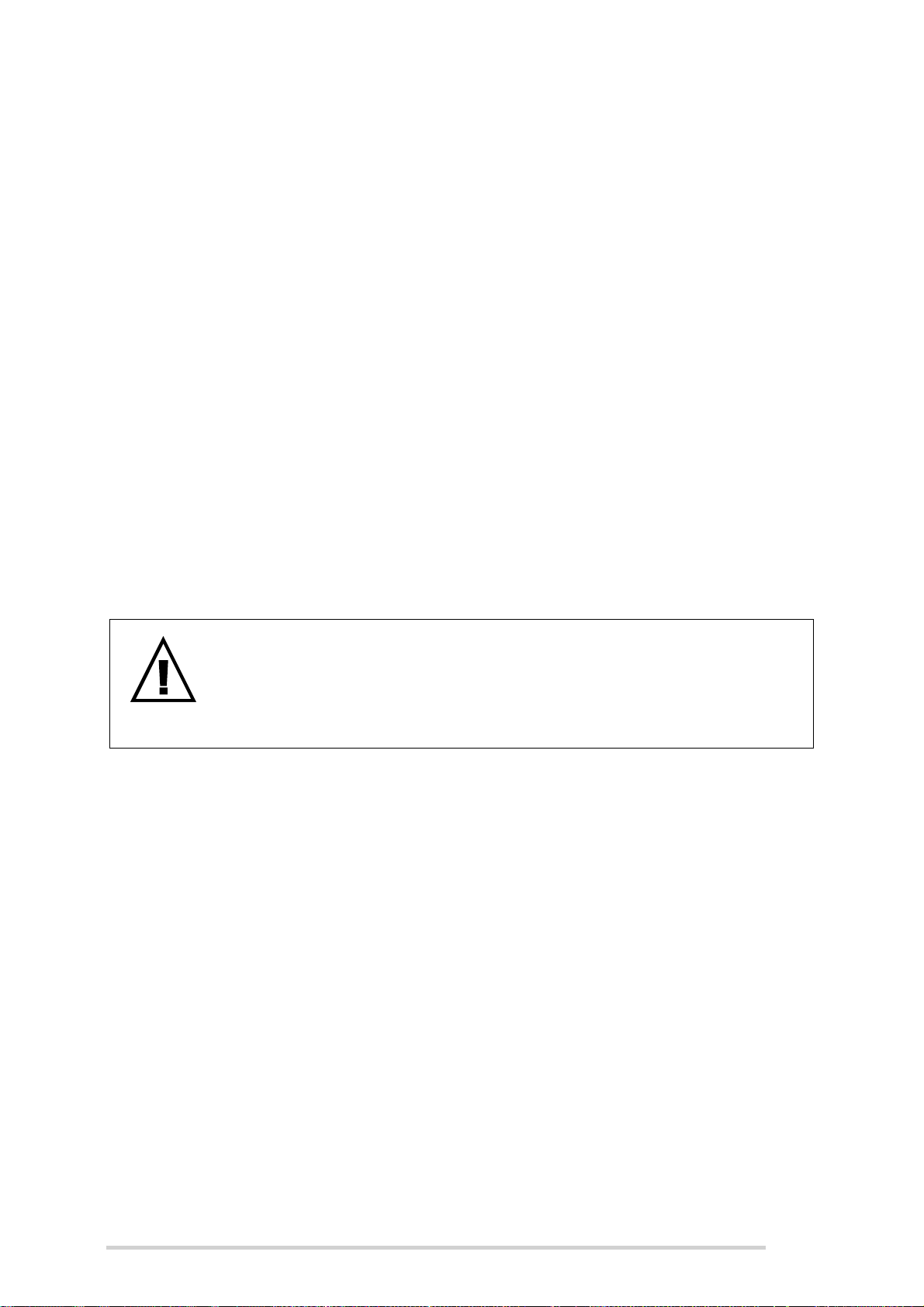
Procedure to select open/closed centre valve configuration:
1. Using a 17 mm spanner, loosen locknut (1) as shown below
2. With a 4 mm Allen key, tighten or unscrew the bolt (2) according to the following
guidelines:
(a) Open Centre (Factory Default): Screw in fully (Do not overtighten)
36
(b) Closed Centre/Load Sensing: Unscrew 5 full turns from the fully in
3. Re-tighten 17 mm locknut. Tightening Torque = 20 Nm
Tightening torque = 6.0 Nm
position
Page 37
McHale Fusion 3 Baler & Wrapper
Figure 5.b - Hydraulic spool valve setup
5.10 Attaching hydraulic hosing to the tractor
WARNING: Turn off tractor and remove key before connecting
hydraulic hosing
When connecting hydraulic hosing to the tractor, ensure that the tractor
engine is turned off and that the ignition key is removed. Ensure that all
hydraulic connections are correctly tightened.
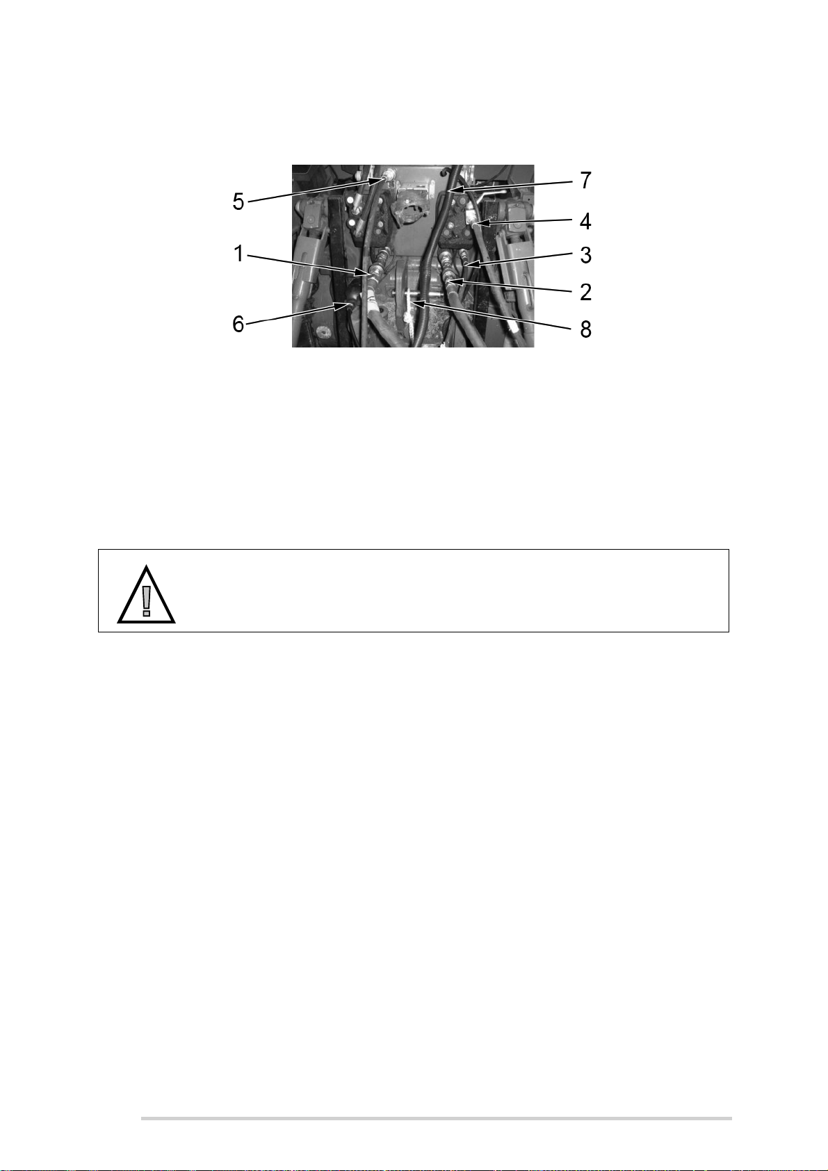
There are a total of five hydraulic hoses (four on air brake models)* and three electrical
connections that must be connected to the tractor. They are as follows:
1. One ¾” female quick release for return line. It must be noted that the return line
much have a free flow to the tank. (Where a ¾” coupling is not available on the
tractor, a special ½” male quick release is supplied with the Fusion 3 in the
toolbox and should be used to replace the ¾” coupling fitted)
2. One ¾” male quick release for feed line (Where a ¾” coupling is not available
on the tractor, a special ½” male quick release is supplied with the Fusion 3 in
the toolbox and should be used to replace the ¾” coupling fitted)
3. One ⅜” male quick release for load sensing (if tractor is load-sensing)
4. One ½” male quick release for pickup reel (with on-off tap)
5. One hydraulic brake coupling *
6. One 12 V / 7 pin lighting socket
7. One 12 V / 20 Amp euro socket (Machine loom to control box shown)
8. One break away rope fixed securely to the tractor
* In the case of air brakes, there must be two air brake couplings available
37
Page 38
McHale Fusion 3 Baler & Wrapper
See the following figure for possible piping layout. Ensure that the machine operator is
familiar with all tractor connections and fittings.
Figure 5.c - Possible layout of hydraulic hosing and electric looms
5.11 Connecting the control box
The control box is to be connected to a 12 V / 20 Amp power supply either using the
supplied euro socket or the battery power cable. A good power supply is critical for
proper machine operation as the electronic control box is the main interface between
the operator and the machine.
CAUTION: Do not connect control box to a 24 V power supply
Do not attempt to connect control box to a 24 V power supply, as
machine component damage will result.
38
Page 39
McHale Fusion 3 Baler & Wrapper
6
Baler Requirement s & Preparation
6.1 Net requirements
In order for the McHale Fusion 3 to produce well-shaped bales of excellent density, a
top quality net, that is as similar as possible to the specification recommended below,
should be used. It is of the utmost importance that the net is used and stored according
to the instructions of the net manufacturer.
NOTE: Minimum turns of net recommended
For netting silage, a minimum of two layers of net is recommended.
When the material is drier, the netting amount should be increased to
four or more turns. A general rule to follow is to apply the amount of net
that will maintain the bale size. The maximum bale size recommended is
a 1.3 m diameter bale.
McHale recommend the use of a net roll which meets the following specifications:
Material: High quality, high density polyethylene
Density: Minimum of 10 g/m ± 10%
Elongation: 15% ± 3%
Strength (in direction of wrap): 900 N/500 mm
Material Length: 2,000 - 4,000 m ± 200 m
Material Width (ideal): 1,230 mm (Max. 1,260 mm)
ENVIRONMENT: Recycling of the Net Roll
Respect the environment! Never throw away or burn the waste net and
the core tube. Always take waste materials to a recycling centre.
6.2 Care of the net roll
The net roll should be protected from damage and moisture. Do not remove protective
cover until ready for use. Net damage can cause undesired netter performance and
affect bale weatherability.
39
Page 40
McHale Fusion 3 Baler & Wrapper
6.3 Care of the net wrapping system
Before operating the baler, ensure that the following procedure is followed to ensure
improved netter operation:
Clean off rubber and metal feed rollers and check for any tacky material
Once roller cleaning is carried out, ensure to apply talcum powder to the
rubber feed roll
NOTE: Cleaning Solvents
Never use cleaning agents such as benzene, petrol, turpentine oil or
similar cleaning solvents to clean rubber feed roll, otherwise damage
may occur!
McHale recommend using either of the following:
A cloth soaked in dish washing liquid
Soapy water
6.4 Loading & operating the netter system
WARNING: Lifting full net rolls
Pay attention to the heavy weight of the net roll. It is recommended that
full net rolls should be handled by two people.
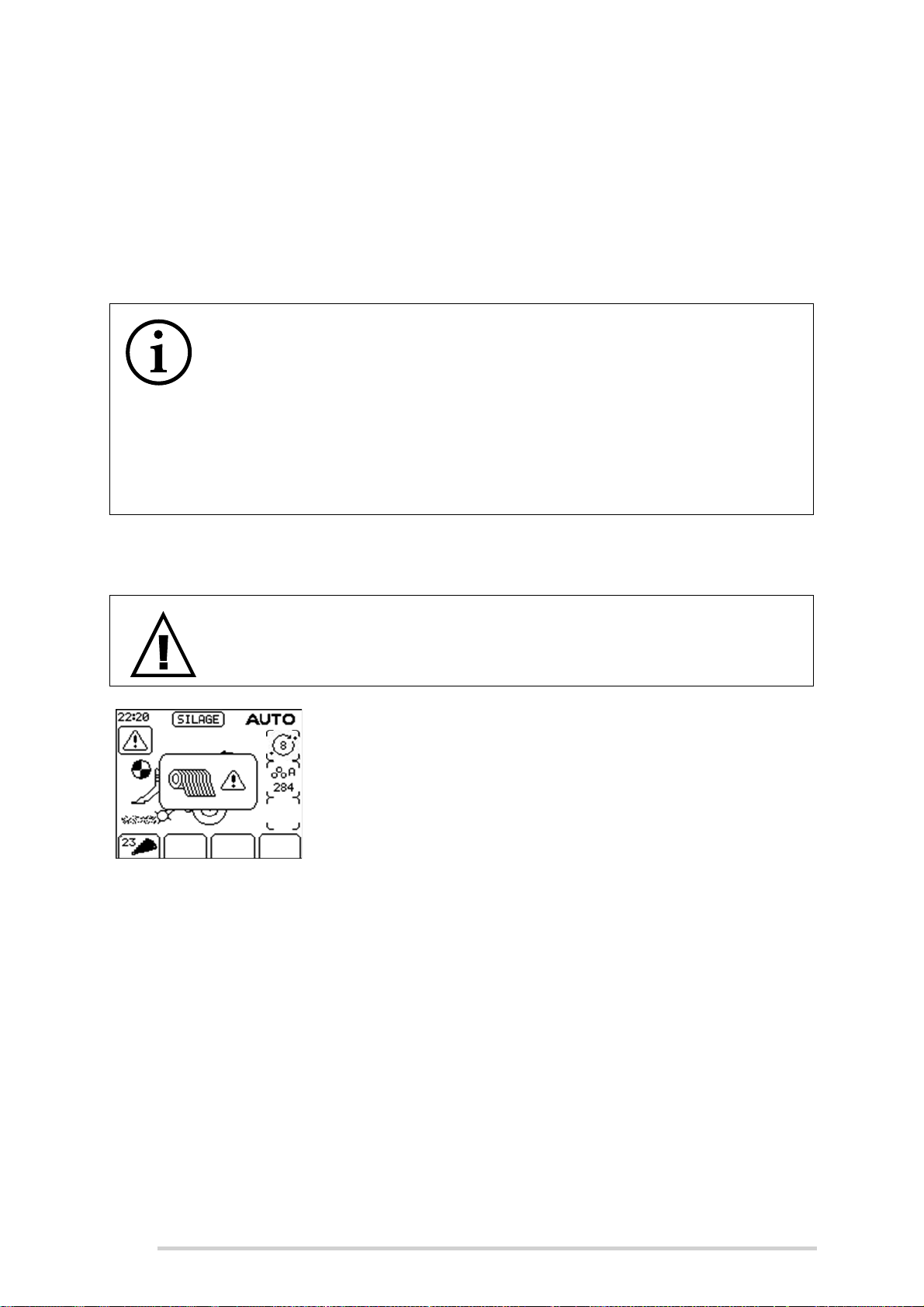
The passage of net through the netting unit is monitored; if
the net cutting knife does not trip within 20 seconds of the
netter starting, the alarm sounds, the net error symbol is
displayed in the control box display and the cycle is halted.
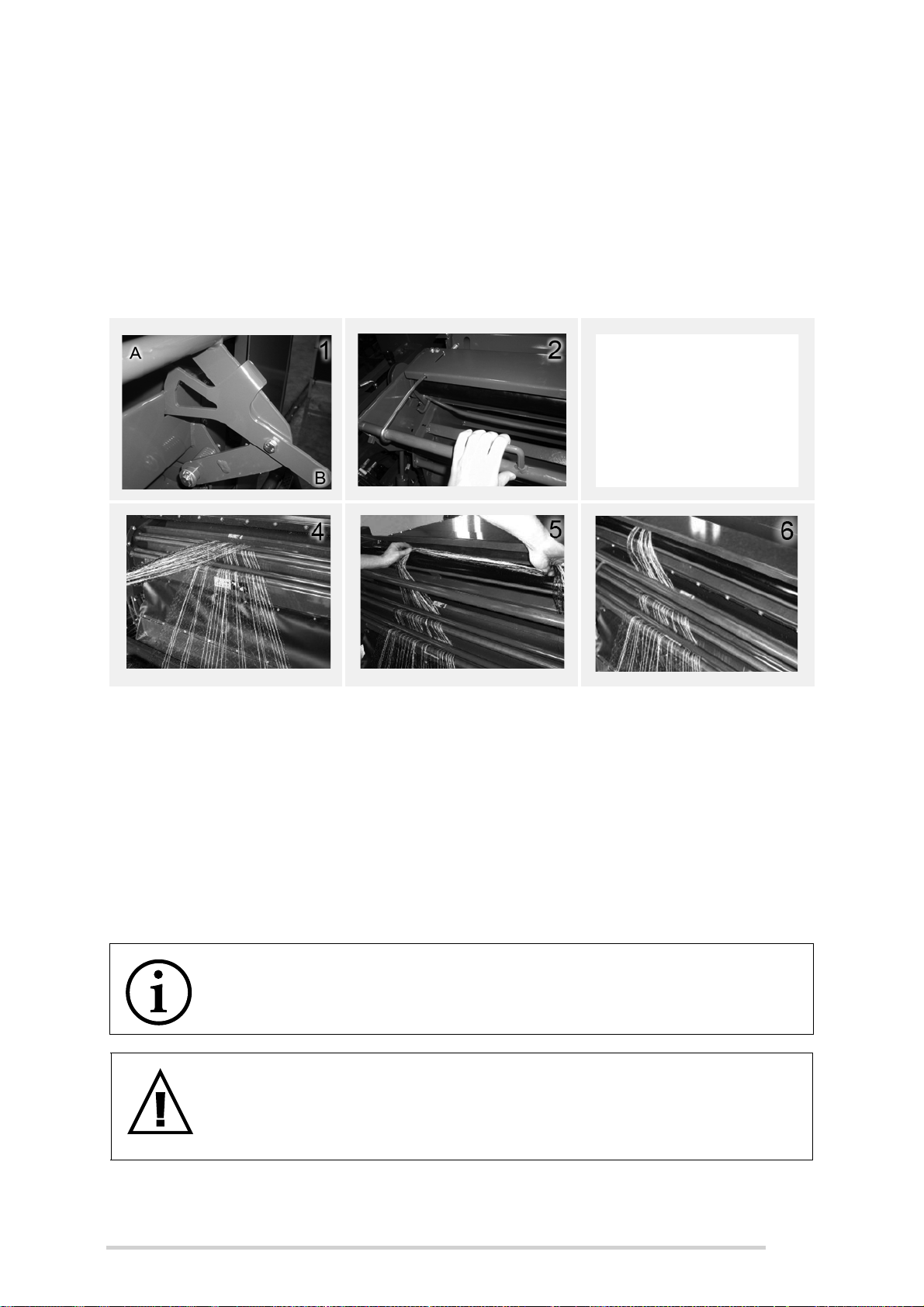
The following is the procedure for changing a roll or fitting the first roll:
1. Ensure the PTO is disengaged, the tractor is shut-down and ignition key has
been removed.
2. Open the net brake bar (A), hold it in place with latch (B), as shown in Image
1. Remove the empty cardboard core of the finished net roll and dispose of
responsibly.
3. Place the new roll of net in the net container.
4. Open the net cutter bar as shown in Image 2 and pull loose net end of approx.
0.5m from the roll. Feed the net through the net tension bar and over the knife
trip bar as show in Image 3.
5. Roll up the net and rest it across the rollers from left to right or vice versa, as
shown in Images 4 & 5, inserting it between the rubber and the metal feeding
rollers.
40
Page 41
McHale Fusion 3 Baler & Wrapper
6. Finally close the net cutter bar, followed by the net brake bar (A) of the net
container, as shown in Images 1 & 2. The loose net end should not be more
than 10cm inside the bale chamber to prevent it being pulled in by the rotating
bale. When finished the net should look like Image 6.
7. After the roll of net is replaced, the tractor & electronic control box is powered
back up, PTO engaged & the “net” button is pushed, the net feeds into the
chamber, netting the bale and the knife trips; the operator then checks that
netting is complete & advances the cycle by pushing the “chamber door open”
button for one second, work can then continue as normal.
Figure 6.a - Adjustable position
6.5 Net cutter setting
In an automatic cycle, the netter starts feeding net once the set bale density has been
reached and the cutter is tripped; the bale is then wrapped with the predetermined net
length. The net length can be adjusted at the net cutter drive on the left hand side, see
Figure 6.e. It is recommended that a minimum of two (2) layers of net are applied to the
bale. Dry conditions and very high densities require up to four (4) or more layers to
ensure a good bale shape.
NOTE: Hay or straw with a high dry matter needs more net
When the control box is set to “Bale Only”, for hay or straw being baled
with high dry matter, more net must be applied.
WARNING: Adjusting the net adjustment lever
Never adjust the net adjustment lever while the baler PTO shaft is
engaged and the tractor is running. Never climb onto the baler platform
while the pick-up reel is still spinning! Beware of sharp knife edges.
41
Page 42
McHale Fusion 3 Baler & Wrapper
Knife tripped, bill hook off adjuster!
CAN ADJUST
Knife not tripped, bill hook on adjuster!
DO NOT ADJUST
Knife
Frame
Less Net
More Net
CAUTION: Adjusting the net cutter
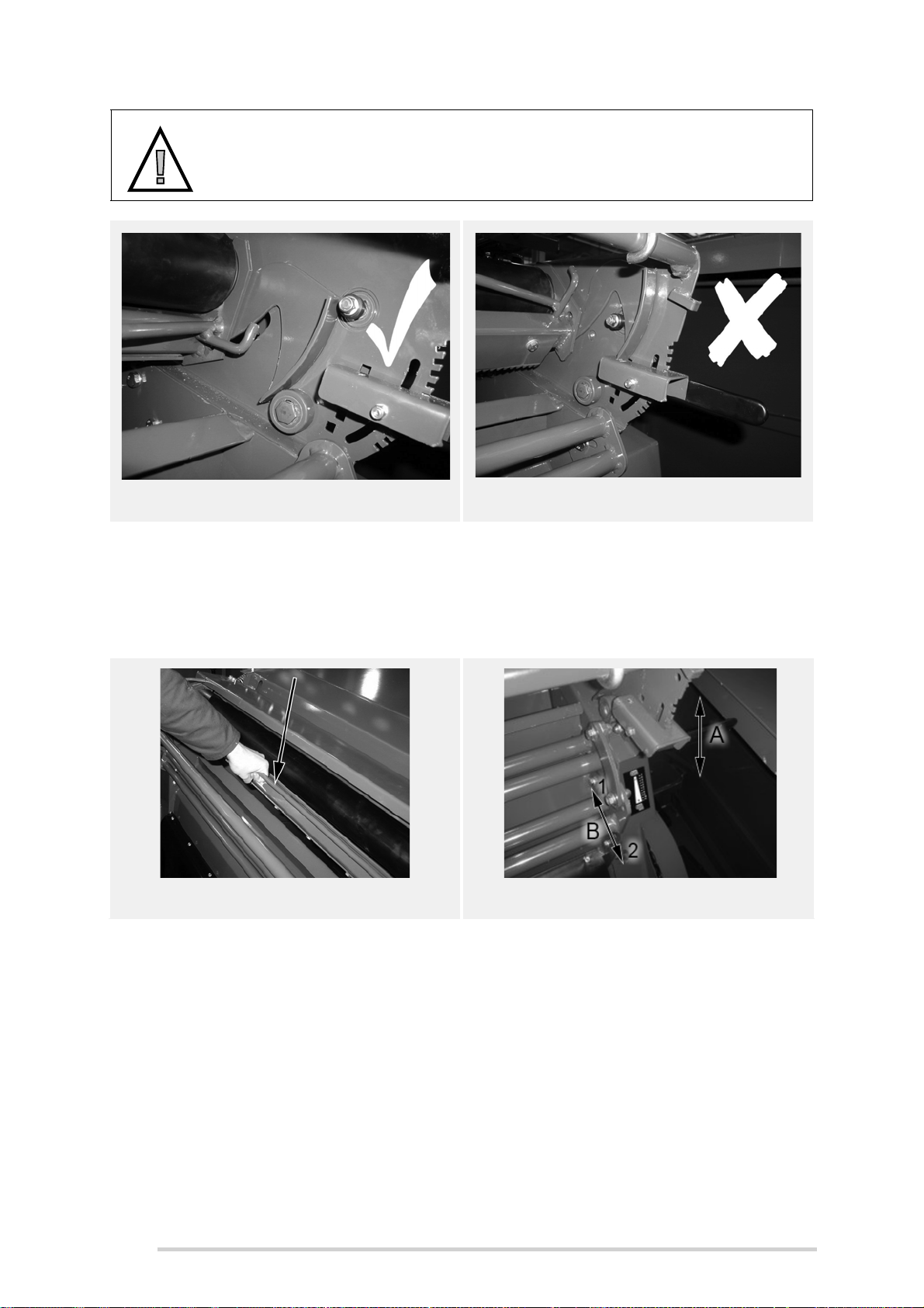
Never attempt to adjust the net cutter setting until the knife has tripped,
see Figures 6.b and 6.c.
Figure 6.b - Adjustable Position Figure 6.c - Non-Adjustable Position
If the knife hasn’t tripped, trip the knife by following the procedure below:
1. Ensure the PTO is disengaged, the tractor is shut-down with the ignition key
removed and the machine is safely parked with wheels chocked, i.e. cannot
roll.
Figure 6.d - Knife bar frame
Figure 6.e - Net cutter setting
2. Climb onto the baler platform. Carefully pull upwards on the knife frame bar,
see figure 6.d, and while applying upwards pressure on the bar, release the bill
hook, by pushing it off the adjuster. Refer to figures 6.b and 6.c.
3. Allow knife to return to it’s spring loaded position.
4. Adjust the net amount adjuster accordingly, refer to table 6.1 “Calculated net
settings”for settings.
5. Once the desired setting is selected, replace the bill hook onto the adjuster by
pulling upwards on the knife frame bar. Ensure that the bill hook rests on the
adjuster, as shown in Figure 6.c.
Adjustment is achieved by pushing the adjustment lever (A) to the right in order to
release the latch from the notches. Choose the desired notch, upwards or downwards,
for less or more net, to be applied as shown in figures 6.e before re-engaging. The
42
Page 43
McHale Fusion 3 Baler & Wrapper
notches are sequenced from top to bottom and are numbered from 1 to 8 respectively.
See Table “Calculated net settings” for exact amount of net applied for each specific
notch.
Notch (#) Layers of Net* (#) Length of Net* (m)
1 2 7.25
2 2.25 2.25
3 2.5 9.25
4 2.75 10.25
5 3 11.25
6 3.25 12.25
7 3.5 13.25
8 3.75 14.25
Table 6.1 - Calculated net settings
NOTE: Figures in table 6.1 are approximate
Figures in table 6.1 are calculated assuming a bale circumference of
3.77m (diameter of 1.2m). The values of the layers and length of net will
be approximate due to differing bale diameters, varying crop conditions,
etc.
6.6 Net tension bar setting
The factory set position for the net tension bar (B), shown in Figure 6.e, is in the centre
of the adjustment slot. Moving the bar forwards, in direction (2) reduces the amount of
net tension, while moving in the opposite direction (1) increases the amount of tension
applied to the net.
6.7 Chopper unit knife removal & installation
WARNING: Incorrectly installed knives can cause irreparable
damage
Incorrectly installed knives can cause irreparable damage to both the
knives and the rotor, leading to serious destruction within the machine!
CAUTION: Use protective gloves
Use protective gloves for any manual work in this area! The number of
knives installed, determines the cut length of the material.
43
Page 44

McHale Fusion 3 Baler & Wrapper
Lock-pin
Locked ‘Closed’ Position
Unlocked ‘Open’ Position
Knife installation/removal should be carried out in the following way:
1. Ensure the knives are in the UP/ON position, before beginning
2. Lower chopper unit floor half way (control box must be in manual mode).
Press “floor-down” button for one to two seconds approximately.
3. Open the chamber door to the fully up position
4. Set the pick-up-reel wheels to working position to make access under the
machine easier
5. Using the lever valve (A), lock the chamber doors in position, by rotating it 90°
to the left vertical position, as shown
6. Shut down tractor, remove key, apply parking brake and prevent any
machine movement with wheel chocks.
7. The knife lock/unlock lever (B) is located on the left-hand side of the chopper
unit, just behind the pick-up reel. It must be pulled outwards at first, to
disengage from the lock-pin, then turned 90° downwards, to the unlock
position, as shown below. Reverse this procedure to return to the locked
position.
8. Removal of knives/blanks is the reverse of the following installation
procedure. Pay particular attention to all decal warnings and safety advice.
9. Rotating lever “B” exposes “flats, on the lock-shaft which allows either knives
or knife-blanks to be added or removed. Remove old knives with a pair of
44
pliers.
Page 45
McHale Fusion 3 Baler & Wrapper
Rotate knife down whilst pulling
towards back of slot in drop-floor
Knife engages with Actuator-arm
Push knife forwards
Push knife forwards
Knife Lock-shaft open
Flats horizontal
Knife retaining magnets
Approx
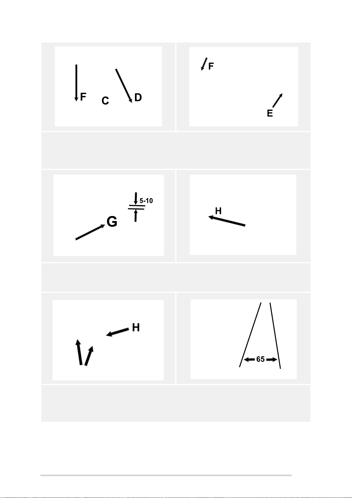
10. A new knife (C) can be installed by inserting into the back of the slot in the
drop floor (D), so it engages with “raised” actuator arm (E). Next rotate knife
downwards (F) whilst continuing to hold towards back of slot, until front
toothed area looks like it will clear front end of slot by 5-10 mm (G), as shown.
11. Now push knife forwards, continuing to maintain this 5 to 10 mm clearance
under front of slot. The keyhole-slot on the front end of the knife should now
guide itself over the “flats” of the lock-shaft (H).
12. Continue to push the knife forward until fully home, which should leave a gap
between the knife and back end of slot of approx. 65 mm (J), with maximum
protrusion of approx. 190 mm (K) (assuming knife-actuators are fully up). The
retaining magnets will hold knives in position until knife lock-shaft is closed.
45
Page 46
McHale Fusion 3 Baler & Wrapper
Max
Knife correctly positioned within
lock-shaft & actuator-arm
Push Blank forwards
Push blank forwards
then rotate down
Blank forwards fully,
engage within lockshaft
Knife lock-shaft
closed
Flats vertical
Knife correctly
positioned within
lock-shaft & actuator-arm
MAX
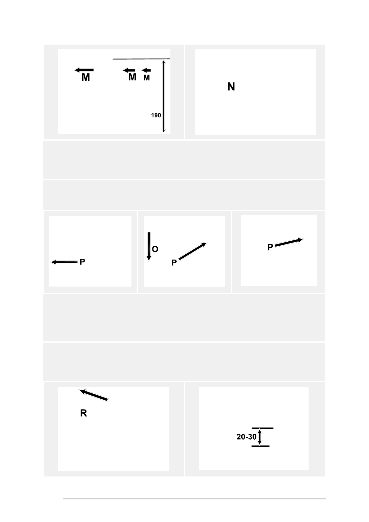
13. After installing, push the top of each knife forward as shown, in the direction
of the arrow (M), to ensure proper engagement within both lock-shaft and
actuator-arm. If the knife moves, then it is not positioned correctly. The
correct position is shown at (N).
14. If knives are removed, for whatever reason, always replace with knife blanks
to prevent crop catching in the “open” slots. These are stored in the knife
holster. See “Knives/Blanks Storage” on page 47.
15. Installation is simpler, in that they only engage with the lock-shaft in front and
not with the actuator-arm. The knife-blank is dropped into slot towards front,
again maintaining the 5 to 10 mm gap (G), push forward (P), allowing the
keyhole-slot to engage with lock-shaft. Then rotate downwards (O) and push
forward fully.
16. Always observe the row of knives after installation. They should all be
perfectly aligned and at the exact same height. If one or more do not line up,
then they are not correctly positioned. Typically the lowest and furthest
forward are correct.
46
Page 47
McHale Fusion 3 Baler & Wrapper
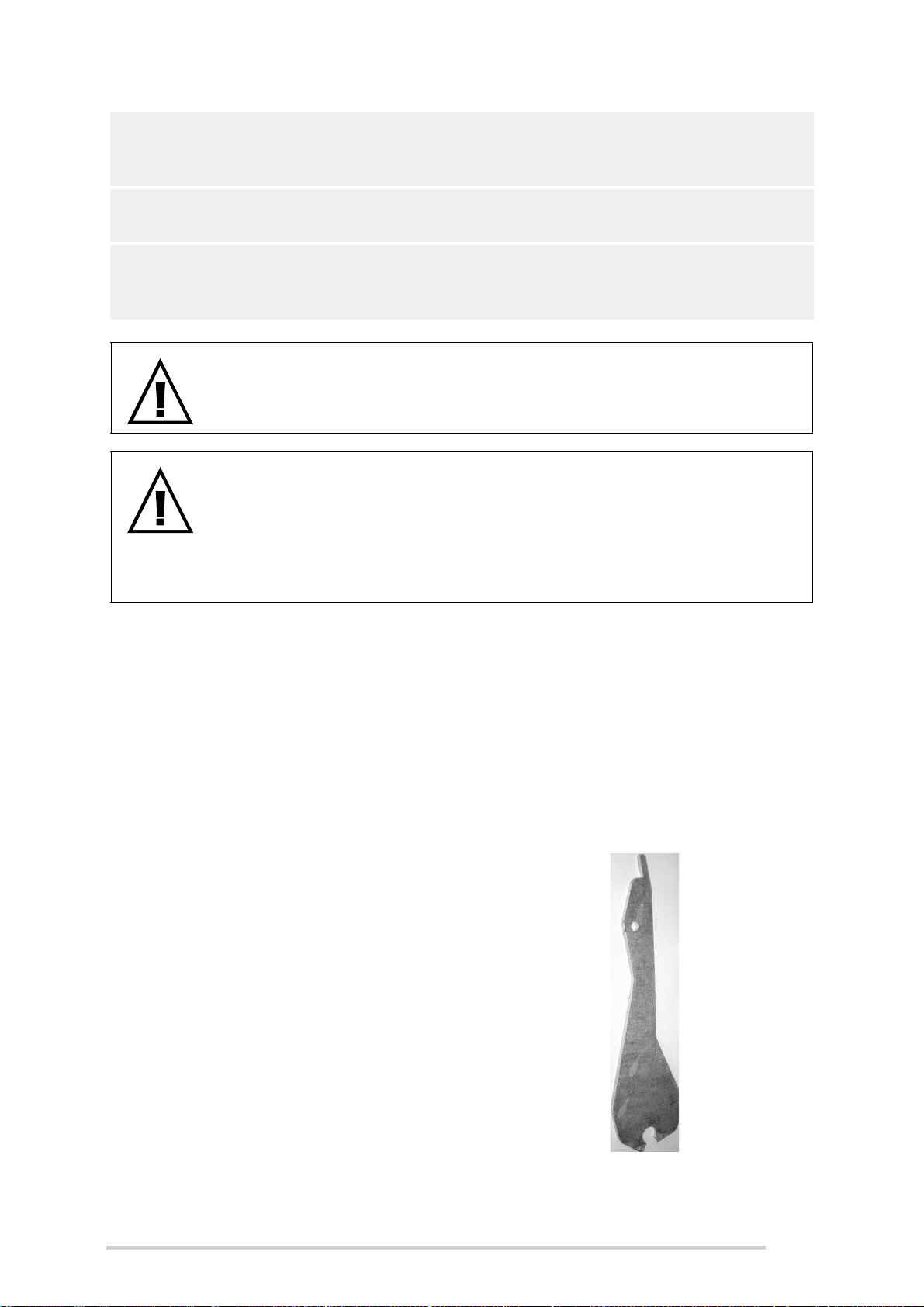
17. Here the knives are shown fully down/retracted, with lock-shaft returned to
the “locked” position (R). Knife tips should protrude 20 to 30 mm maximum
(T).
18. Rotating lever B back up to 90° onto lock-pin, locks all knives/blanks
securely.
19. The knife blanks are stored in the knife/knife blank holster which is located in
the front left compartment of the Fusion 3. They are to be used any time one
or more knives are removed.
.
WARNING: Turn the levers back into their working position
Do not forget to turn the levers back into their working position(s), but
only after completing all work on the machine as shown.
WARNING: Compartment doors panels must be closed while the
machine is running - danger of rotating components
Always keep the compartment door panels closed while the machine is
running because of the danger of rotating components! Take note of all
warning decals and ensure that all safety measures and precautions are
implemented before attempting to carry out any maintenance work.
6.7.1 Knives/Blanks Storage
The knife blank holster has two methods of retention, L and S, as shown in Figure 6.f.
Upper pin L can be pulled out from the left by first removing the pin on the right. The
lower pin S is used as a clamping device, to prevent knives/blanks from vibrating and
can be loosened by turning anti-clockwise and tightened by turning clockwise.
Removal of knives/blanks is the reverse of the installation procedure. Pay particular
attention to all decal warnings and safety advice.
Figure 6.f - Knives/Blanks Storage Figure 6.g - Knife blank
47
Page 48
McHale Fusion 3 Baler & Wrapper
Sharpen this side
6.7.2 Knife sharpening
The knives in the chopper unit should be sharpened on the
flat side using either a file or a mopping disk. The knife
should never become hot while sharpening, otherwise it will
lose it’s tensile.(Sharpen along the flat edge on this side
only)
WARNING: Never use a grinding disk
Never use a grinding disk when sharpening the knives.
6.8 Automatic lubrication system
The McHale Fusion 3 is equipped with a fully automatic greasing and oiling system
which is responsible for greasing the roller bearings in the machine baling chamber
(apart from the transfer roller) and oiling of all chain systems. All other grease points
must be greased, as specified in “Machine Maintenance” on page 105.
Figure 6.h - Oil reservoir tank & oil grease
cartridge pump unit
a. Oil reservoir tank
b. Oil filter
c. Air release valve (prevents air locks)
d. Greasing cartridge and pump unit
e. Grease cartridge cover
f. Grease cartridge plunger stop
The oil reservoir tank (A) can hold approximately 5 litres of oil and this is enough oil for
approximately 500 bales. It should be kept between the minimum and maximum
markings at all times. McHale recommend the use of only top quality chain oil and
grease, this will prolong the life of the machine components. A grease cartridge is
required after every 300 bales approximately. On the control box an alarm is provided
to remind the operator to change the grease cartridge and top up the lubrication oil after
a preset number of cycles. This counts down from 300 and gives a reminder at zero. It
48
Page 49
McHale Fusion 3 Baler & Wrapper
may be reset sooner, if desired, from within the control box sub menus. See “Control
box features” on page 60 for instructions on how this is done.
WARNING: Ensure the tractor is shut down before adding oil
Ensure that the tractor engine has been shut down, the key has been
removed from the ignition and the brakes have been applied before
adding oil.
To add oil:
1. Unscrew the top cap and add chain oil to the oil reservoir tank (A), up to the
maximum level mark shown.
2. Replace the cap and tighten fully.
NOTE: Oil filter needs to be replaced at least once every season
The oil filter, inside the oil reservoir tank, will need replacement once
every season or as soon as reduced oil consumption is noticed. The filter
is critical to proper operation and lubrication.
Replacing refill grease cartridge and releasing airlock:
McHale recommend using a multipurpose, extra high performance grease such Mobil
grease XHP222 or equivalent NLGI number 2 grade grease.
CAUTION: Avoid contact of the grease with skin
Avoid contact of the grease with skin
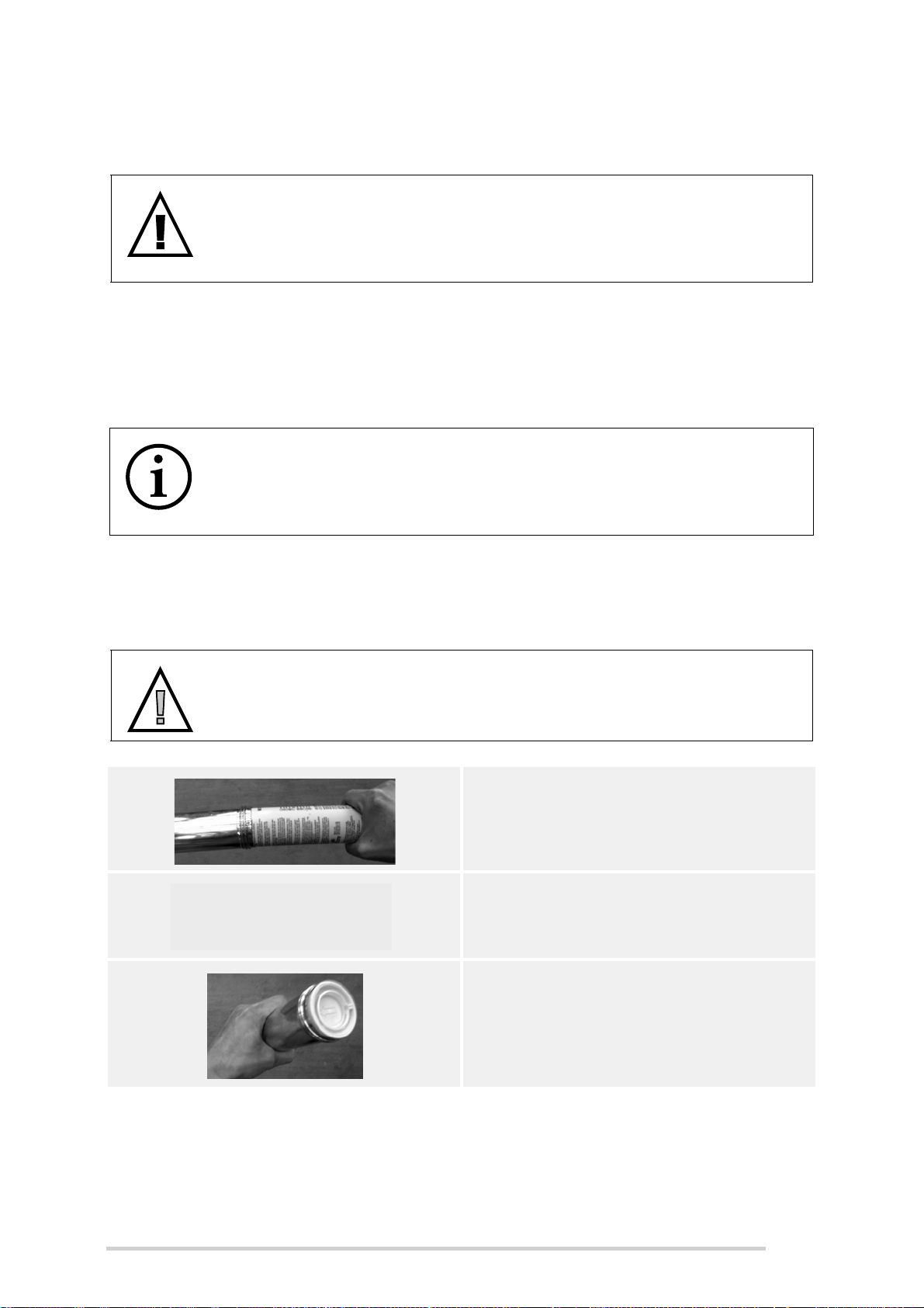
1. Unscrew the cartridge holder from
the pump and remove the used
cartridge
2. Pull the plunger all the way back
3. Remove the cap from the plunger
end of the refill cartridge. Insert the
refill cartridge, as shown
49
Page 50
McHale Fusion 3 Baler & Wrapper
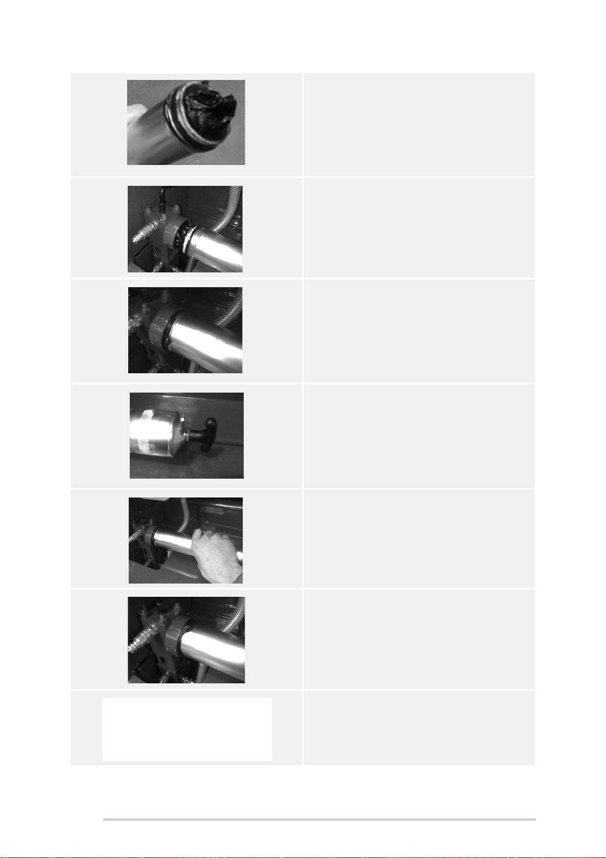
4. Open the refill
5. Screw the cartridge holder onto the
pump, but do not tighten. Only screw
the cartridge by one turn when you
feel the first thread.
6. Rock the cartridge holder from side to
side to ensure it does not fall off
7. Release the plunger and push the
plunger rod all the way into the
cartridge holder
8. Slowly and gently, rock the cartridge
holder from side to side. Air between
the grease pump and the cartridge
will escape. When a bead of grease
starts to leak out, the cartridge can be
tightened fully.
9. Clean off this bead of grease so dust
and debris does not stick to it. This
dirty grease could get into the grease
pump at the next cartridge change,
causing a blockage of the grease
system.
50
10. Drop the plunger lock and top up the
chain oil. Then reset the lube count
on the Expert Plus Control Box.
Page 51
McHale Fusion 3 Baler & Wrapper
6.9 Gear box oil
The gearbox is located to the rear of the PTO shaft.
WARNING: Ensure the tractor is shut down before changing oil
Ensure that the tractor engine has been shut down, the key has been
removed from the ignition and the brakes have been applied before
changing oil.
NOTE: Oil must be drained & filled after the first 5 hours of use
After the first 5 hours of use, the gear box oil must be completely drained
and filled with SAE 80W/90 grade oil.
ENVIRONMENT: Safe disposal of oil
Respect the environment! Never spill oil or grease on the ground, never
pour them down the drain and never discard them where they can pollute
the environment. Always take waste materials to a recycling centre.
To drain and add oil to the gear box, carry out the following procedure:
1. Remove the filler-plug (A) followed by drain-plug
(B), using an 8 mm Allen key, and drain oil into a
suitable container. This is best carried out while the
oil is still warm, i.e. soon after use. Replace the
drain plug (B), tighten and dispose of waste oil
responsibly.
2. Remove the level-plug (C) and add between 2 and
2.2 litres of SAE 80W/90 grade oil, or until oil begins
to seep out at C. After this replace the oil once per
season or once per 10,000 bales, whichever comes
first.
3. Replace the level-plug (C) followed by filler-plug (A)
and tighten carefully.
NOTE: Do not overfill the oil
Do not overfill the oil, as this will result in overheating and oil leakage.
6.10 Tyre inflation pressures
CAUTION: Check the tyre pressure weekly
Check the McHale Fusion 3 tyres weekly for the pressures outlined in
the following table.
51
Page 52

McHale Fusion 3 Baler & Wrapper
Tyre type Pressure
560/60 R22.5 1.65 bar (24 P.S.I.)
650/50 R22.5 (Optional Specification) 1.65 bar (24 P.S.I.)
170/60 - 8 (Pick-up tyre) 2.07 bar (30 P.S.I.)
6.11 Wheel chocks
Wheel chocks are provided to secure the baler wheels anytime the baler is to be
detached from the tractor, or if the machine is to be stored or parked up. They are
located on the left of the machine, inside the main panel, while in the transport position.
Figure 6.i - Wheel Chocks
6.12 Drawbar and PTO shaft stand usage
There are three (3) types of drawbar stands available on the Fusion 3, depending on
the country of use, one will come as standard:
1. A swing down fixed length stand (low hitch) - Type A
2. A swing down screw stand (low hitch) -Type B
3. A fixed screw down stand (high hitch) - Type C
The drawbar stands are to be used every time the machine is disconnected from the
tractor.
CAUTION: All stands must be rested on a solid footing
All stands must be rested on a solid footing, on level ground and also
supplied wheel chocks must be used.
52
Page 53
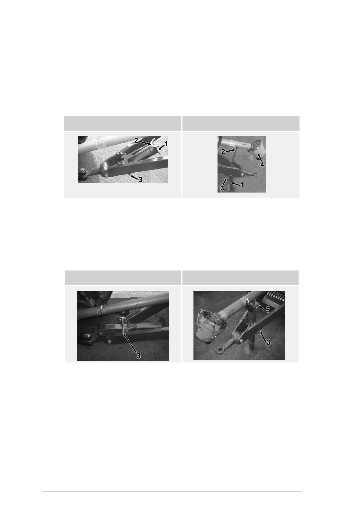
McHale Fusion 3 Baler & Wrapper
Type A - The following applies to the swing down fixed length stand (low hitch):
Transport working position: While using the machine, ensure that the drawbar
stand (1) is raised full with stand pin (3) in alternate hole position and ensure
PTO shaft stand (2) is in the lowered horizontal position.
Storage position: Ensure that the stand pin (3) is properly placed in the lower
slot to prevent the stand from collapse. Then place PTO shaft stand (2) in an
upright position it in order to support the PTO shaft (4).
Transport (Working) Position Storage Position
1
Type B - The following applies to swing down screw stand (low hitch):
Similar to type “A”, except stand pin (3) is in the upper slot, in the transport
(working) position. It should be wound up and retracted fully as shown before
removing the handle. The main difference being, that the drawbar height is
now fully adjustable and the PTO shaft stand (5) is an integral part of the
assembly.
.
Transport (Working) Position Storage Position
Type C - The following applies to the fixed screw down stand (high hitch):
Stand type C is the only type supplied with the high drawbar hitch option and
is available as an option on the low drawbar hitch machines.
In order to elevate the drawbar, rotate the jack handle (1) in a clockwise
direction as shown in the figure below. In order to lower the drawbar, rotate
the handle in a counter-clockwise direction.
When the drawbar has been safely connected to the hitch on a high hitch style
tractor and the machine-weight taken off the stand (by rotating jack handle (1)
in a counter-clockwise direction) the lower part of the stand (2) can be
retracted quickly by removing the quick-release pin (3) (having first removed
53
Page 54
McHale Fusion 3 Baler & Wrapper
Drop down PTO stand
the R-clip (4)) and sliding up the lower part of the stand, fully into position.
Align the bottom hole and replace the pin (3) followed by R-clip (4).
The PTO stand (5) can be simply lifted out of the way, once the machine has
1
been coupled to the tractor, with the PT O shaf t connected. Leave the stand in
a suitable location such as the tractor cab, toolbox, etc. available for its next
use.
Depending on the height of the windrow being baled, the stand may need to
be elevated further, in order to avoid catching crop. This is done by rotating
the jack handle (1) in a counter-clockwise direction until it is fully retracted.
6.13 Drawbar adjustment
WARNING: Adjustment to be completed by qualified persons only
This work should only be carried out by qualified persons or your
McHale dealer!
This adjustment should be carried out on a level concrete surface, with the tractor
drawbar aligned such that the exact adjustment can be monitored. Ensure that the
tractor engine has been shut down, the ignition key removed and the brakes applied.
The machine handbrake must be applied, the main wheels chocked, with the front end
of the machine (under the chopper unit) supported on axle stands. The drawbar should
be adjusted so that the machine is level and horizontal to the ground when in the
working position, see figure “Drawbar adjustment” below. To adjust, first remove the
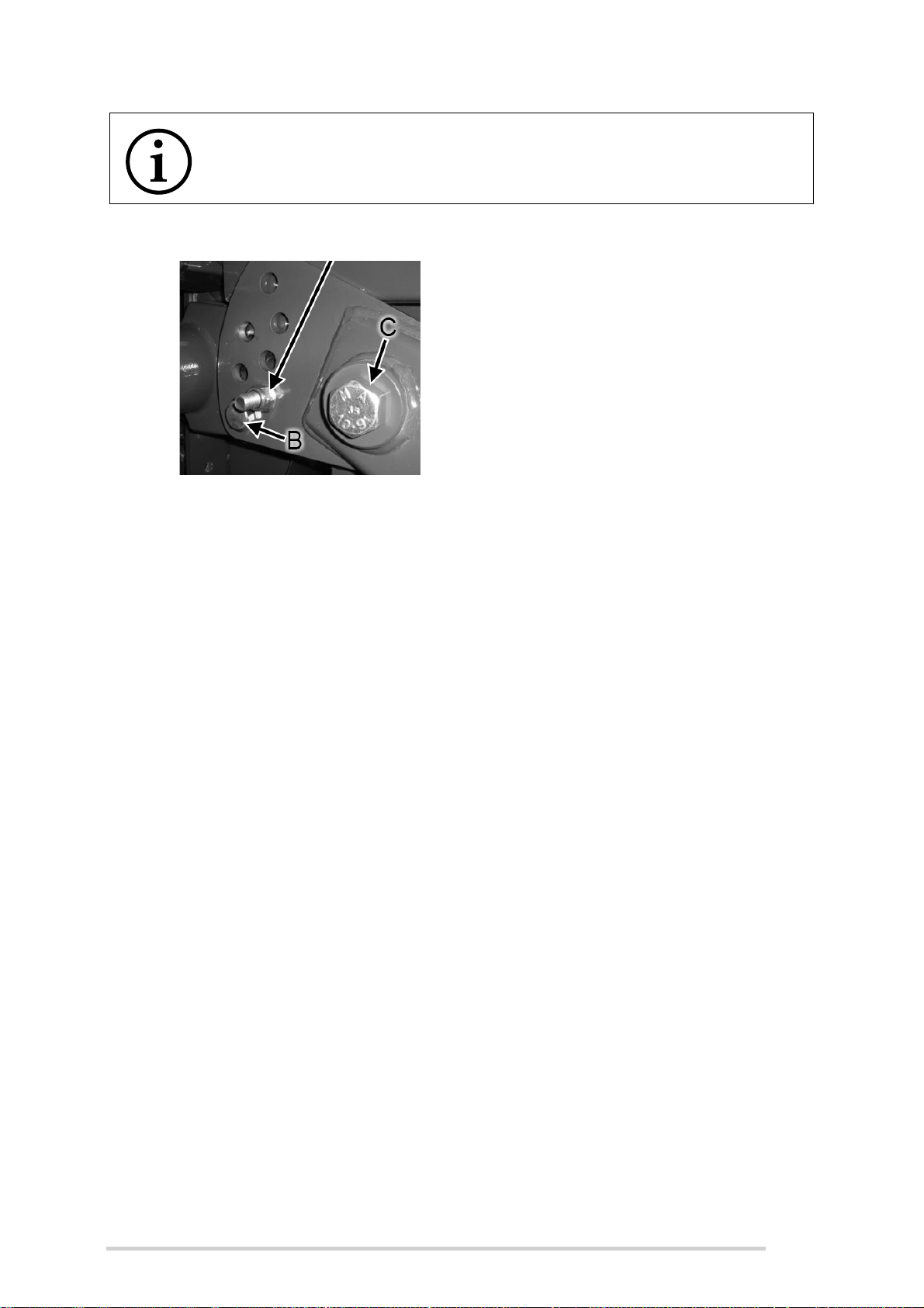
safety-bolts, then slacken the hinge-bolts (C), but do not remove. Hitch-eye can be
adjusted to different height positions by repositioning bolts (B) in alternating hole
positions. It can then be re-adjusted locally by loosening bolts (A & D) to ensure it is
level. Once the desired height is achieved, ensure that bolts (A & B) are tightened to a
torque value of 540 Nm and the 30 mm top drawbar hinge-bolts (C) tightened to a
torque value of 1060 Nm. Tighten bolt (D) and reposition and tighten safety-bolts.
54
Page 55
McHale Fusion 3 Baler & Wrapper
Safety Bolt
Hitch Eye
.
NOTE: The drawbar bolts must be inspected every two weeks
The main drawbar bolts (A & B) along with hinge-bolt (C) must be
inspected once every two weeks.
Figure 6.j - Drawbar adjustment
6.14 PTO Shaft adjustment & maintenance
The length of the PTO shaft is suitable for all known tractor conditions. However, before
the machine is operated for the first time with a new tractor combination, it must be
ensured that there is a minimum sliding clearance of 200 mm left during all angles
between the tractor and the machine. In a case where there is not sufficient sliding
clearance the shaft length must be adjusted according to the PTO shaft manufacturer’s
recommendations that are either attached to the PTO shaft or included with this manual
or both. Maximum 80° angle of movement should never be exceeded, otherwise
permanent damage will result (See Figure 6.l).
All PTO shaft grease points are to be serviced at 60 hour intervals.
55
Page 56
McHale Fusion 3 Baler & Wrapper
The recommended quantities of grease in grams for each grease-point are shown (See
Figure 6.k).
Figure 6.k - PTO Grease points
Figure 6.l - Max PTO angle
56
Page 57

McHale Fusion 3 Baler & Wrapper
This page is intentionally left blank
57
Page 58
McHale Fusion 3 Baler & Wrapper
7
Electronic Control System
Control Unit Software Version EP301-113 onwards
58
Page 59

McHale Fusion 3 Baler & Wrapper
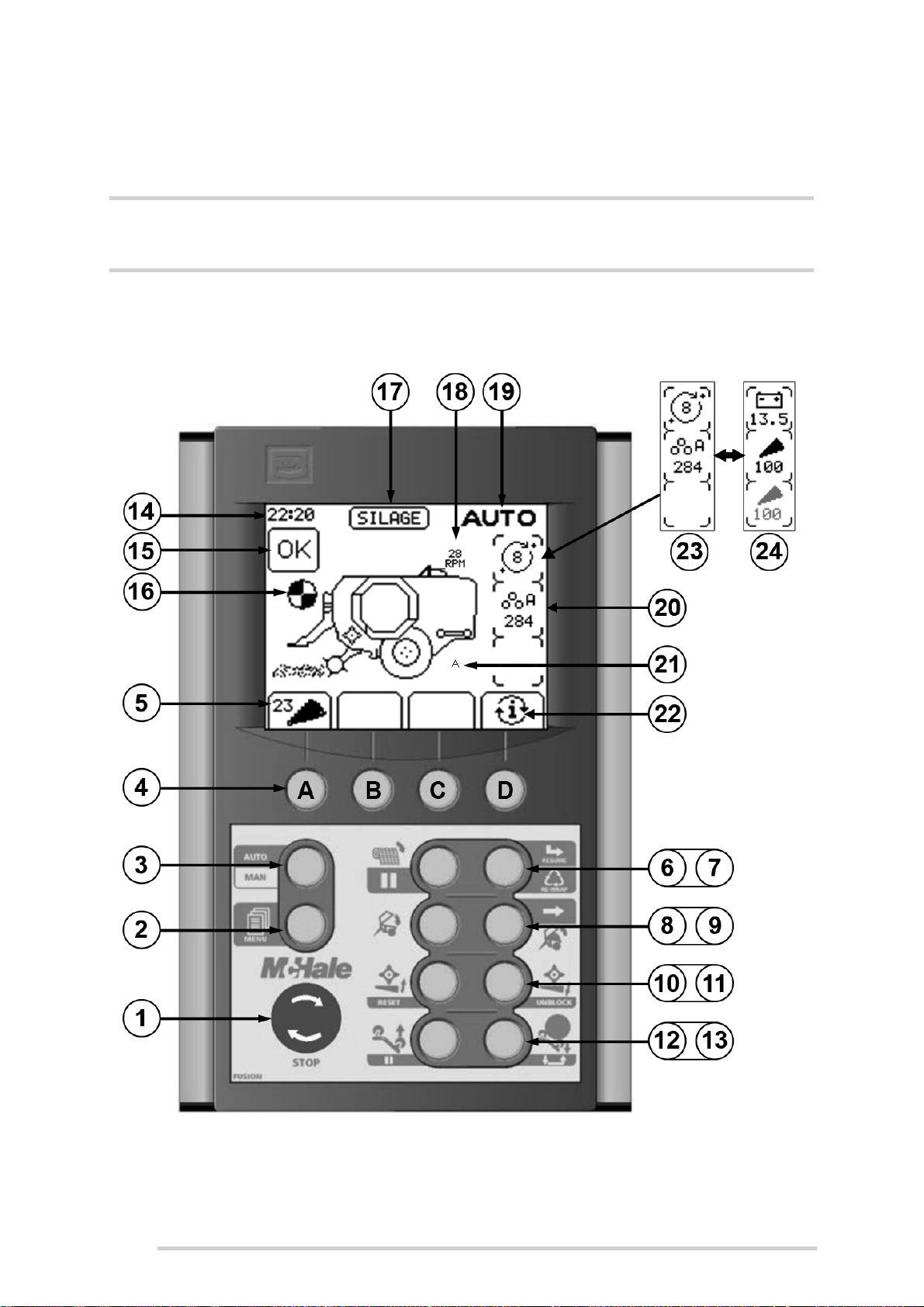
7.1 Control box functions
No. Function
Manual Automatic
1
2
3
4
5
6
7
8
9
10
11
Stop button - Twist clockwise to turn
Menu button
Select Automatic Mode Select Manual Mode
Four soft keys (A, B, C & D) with interchangable functions (each function
relates to the corresponding option directly above it on the screen)
On screen function display of the four soft key buttons below
Net feed Hold to pause netting of the bale
Press to feed net after an error
No function Rewrap or resume wrapping
Close the chamber No function
Open the chamber Open chamber after a net error
Press during transfer to pause Press
once to close after a pause
Raises the unblock floor Press to reset after unblocking
Lowers the unblock floor Hold for 3 seconds to start unblock
12
13
14
15
16
17
18
19
20
21
22
23
24
Raises the bale tipping arm Press to pause tipping of the bale
Lowers the bale tipping arm One press to tip the bale
Clock
Status indicator
Net Indicator (rotates when net is being applied)
Crop type
Wrapper ring RPM
Displays Manual or Automatic Mode
Information display
“A” symbol displayed when Auto tip is turned on
Use Softkey D to toggle between Main Screen 1 & 2
Main Screen 1: symbols/information (alternative to Main Screen 2)
Main Screen 2: symbols/information (alternative to Main Screen 1)
(3rd symbol is visible, with knife numbers, if selectable knives is operational)
59
Page 60
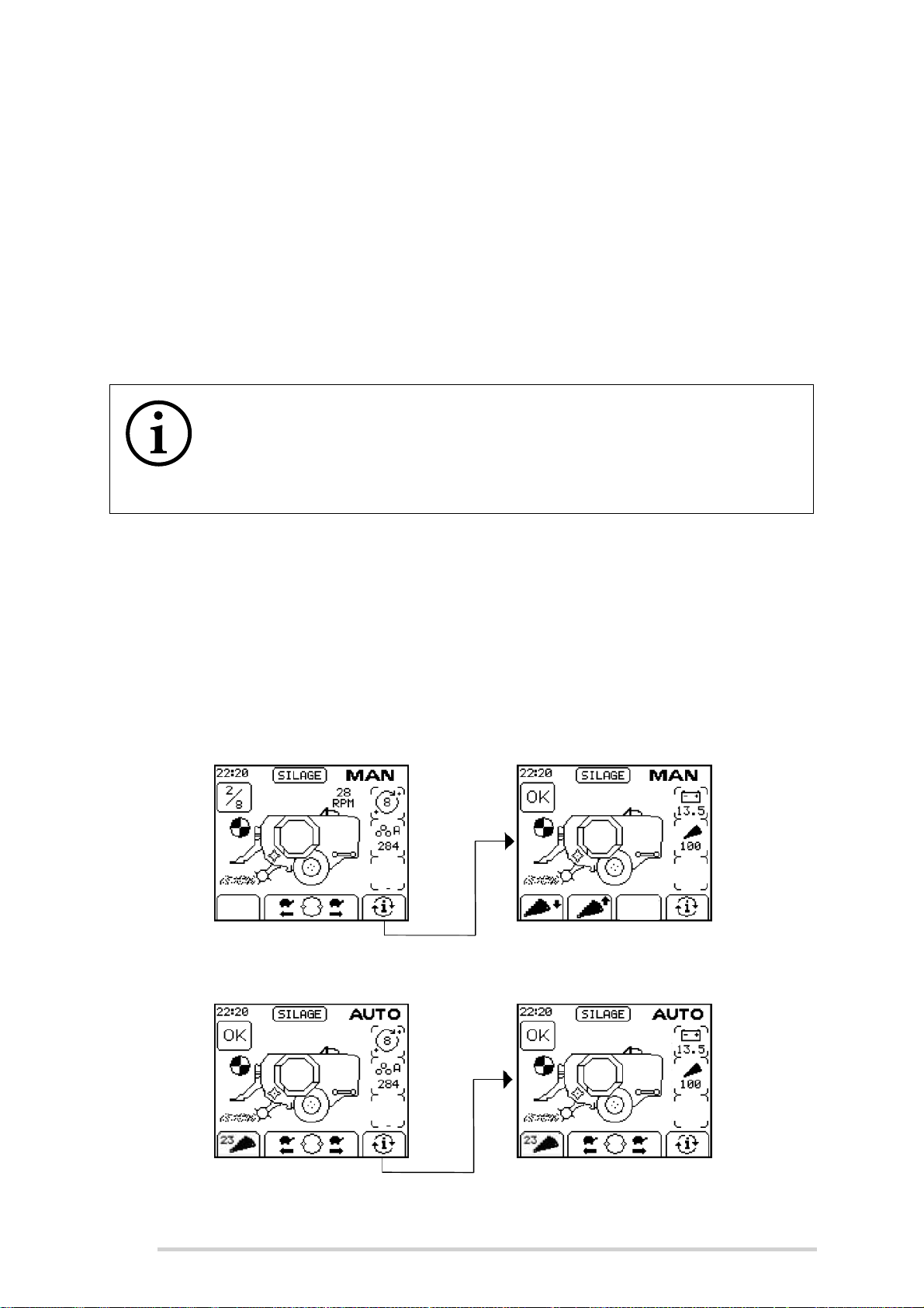
McHale Fusion 3 Baler & Wrapper
7.2 Control box features
7.2.1 Working Display
When the control box is first switched on it displays “McHale Fusion” followed by the
software version number, followed by the selected language. The language can be
changed at this point by pressing the arrow up (Softkey A) or arrow down (Softkey B)
button to scroll until the required language is selected.
After a short delay, the working display appears. The working display features an
image of the Fusion 3, which is surrounded by general working information.
NOTE: The four soft key buttons are used for multiple functions
The four soft key buttons are used for multiple machine functions and
menu navigations. Their function changes depending on the current
screen and relates to the corresponding symbol directly above each soft
key, across the bottom of the screen.
7.2.2 Manual/Automatic Modes
There are two working screen modes:
1. Manual
2. Automatic
To switch between the Manual and Automatic modes, press “Auto/Man” (Button 3). The
selected control mode is displayed in the top right corner of the screen.
Figure 7.a - Manual Screen Display (Screen 1 on LHS & Screen 2 on RHS)
Figure 7.b - Automatic Screen Displays (Screen 1 on LHS & Screen 2 on RHS)
60
Page 61

McHale Fusion 3 Baler & Wrapper
Screen Selection
There are two screen options for the Manual mode and two screen options for the
Automatic mode. The reason for this is to show extra information displays and different
functions for the softkeys.
7.2.3 Crop Types
There are three different crop types to choose from in the menu:
1. Straw
2. Hay
3. Silage
When Hay or Stray is selected, the wrapper will be disabled.
When Silage is selected, the wrapping will be switched on.
7.2.4 Film Layers
The selected number of rotations is displayed on the right side of the screen. On the
left side of the screen, the number of completed wraps over the target number of wraps
is displayed in the status box, when the wrapper is rotating.
7.2.5 Net Indicator
The net indicator (See No.16 of “Electronic Control System” on page 58) rotates when
net is being applied. This stops rotating when the net knife trips to cut the net.
7.2.6 Bale Counters
The bale sub total is displayed on the right side of the screen, if you cannot see it on
the screen, toggle to the other screen display by pressing the softkey D button. The
control box contains ten different bale counters (A-J) which can be reset and a grand
total counter which can not be reset. (See “Bale Count” on page 69)
7.2.7 Voltage Monitor
The control box monitors its operating voltage and displays it on the lower right side of
the screen. If the voltage falls below 10 volts the “LOW BATT” symbol is flashed on
the display.
7.2.8 Dispenser Speed RPM
The wrapper ring rotation speed, in revolutions per minute, is displayed over the
wrapper of the Fusion 3 image on the screen (Shown at No. 18).
61
Page 62

McHale Fusion 3 Baler & Wrapper
Knives up
indicator
Knives
up
Knives
down
Knives down
indicator
Toggle to
select 0 or 23
knives
7.2.9 Manual Wrapping
Softkeys B & C on the main screen 1 are used to manually rotate the wrapper ring.
Pressing and holding the forward (Softkey C) or reverse (Softkey B) once will rotate the
ring slowly. Pressing forward (Softkey C) twice and holding it will rotate the ring forward
at full speed.
In Automatic Mode, the rotate buttons will not be active unless the ring is NOT in the
“home” position.
7.2.10 Knives Operation
Standard Knife Operation allows all 23 knives to be raised/lowered together.
If Manual Mode is selected there are two soft keys active for the knives on the second
working screen. Softkey A lowers the knives and Softkey B raises the knives. The knife
pressure in Bar is displayed on the middle right information display, if you cannot see
it on the screen, toggle to the other screen display by pressing the Softkey D button.
When the knives are raised the pressure will increase and stop at the normal working
pressure, approx. 50 bar.
Sometimes, if the knives have not been used for a while, full pressure may need to be
used. To do this, the “knives up button” (Softkey B) should be released and when
normal working pressure is reached, it should be pressed again.
The pressure will then increase to the maximum allowed and a “Knife pressure too
high” warning will be displayed to warn the operator not to bale with the pressure this
high. To release the pressure, lower the knives fully by pressing “knives down” (Softkey
A) and press it again to raise them and reset the normal operating pressure.
In Automatic Mode, Softkey A is toggled to select the number of knives desired, 0 or
23. The machine will automatically move the knives to the correct position and
constantly monitor the knife pressure and correct it as necessary
A sensor indicates when the knives are fully up. The knife symbol will be shown as
follows (See Figure 7.c):
Completely black when the knives are up
Only an outline of the knife will be shown if they are down
62
Figure 7.c - Standard Knife Operation
Page 63
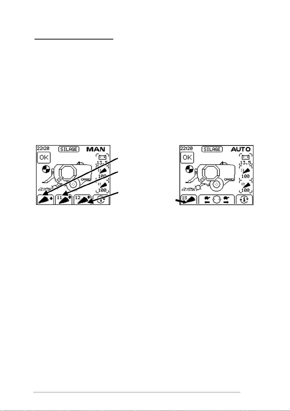
McHale Fusion 3 Baler & Wrapper
All knives down
11 knives
up
12 knives
up
Toggle to
select 0,
11, 12 or 23
knives
Selectable Knives Operation is an optional extra with the Fusion 3 which allows the
selection of 0, 11, 12 or 23 knives from the control unit.
In Manual Mode, there are 2 buttons use to the raise the knives, one for 12 knives
(Softkey C) and one for 11 knives (Softkey B). Pressing “knives down” (Softkey A)
lowers both sets (11 & 12) together. There are two knife pressure displays, one for the
set of 11 knives and one for the 12 set.
In Automatic mode, 0, 11, 12, or 23 knives can be selected. This is done by toggling
the knives button (Softkey A) to the desired knife setting.
A sensor indicates when the knives are fully up. The knife symbol, for 11 & 12 knives
will be shown as follows (See Figure 7.d):
Completely black when the knives are up
Only an outline of the knife will be shown if they are down
(
Figure 7.d - Selectable Knife Operation
7.2.11 Automatic Operation
Automatic operation is the preferred method of operation on a day-to-day basis,
allowing the machine to free-flow through each cycle. Manual operation is generally
used when the user wants to have direct control over individual functions for service/
maintenance reasons.
When the control box is switched on, Automatic mode can be selected by pressing
button 3. AUTO will be displayed in the top right of the screen and the Fusion 3 image
shows crop moving into the pick-up on the screen to show that baling is ready to start.
Netting: As crop continues to build up in the chamber, a series of beeps will sound for
3 seconds when the bale has reached the predetermined density (bale full) to alert the
operator that netting is about to start. The operator must stop the forward movement of
the tractor at once. The “Net Feed” (Button 6) may be held at this point to delay the net
from feeding, if the operator wants to pack a little extra crop into the chamber. Next, a
continuous beep informs the operator that the netting has started. and the wrapped
bale on the wrapper will be tipped off automatically, if “Auto tip” is turned on (See
Section “Auto Tip” on page 67). If the net knife does not trip within 20 seconds, then it
is presumed that there is no net / a problem has occurred and a “check net” warning
will be displayed (See Section “Check net” on page 70). The roll of net can be replaced
and “Net Feed” (Button 6) is pressed to start netting again.
63
Page 64

McHale Fusion 3 Baler & Wrapper
Transfer: After the set number of net layers are applied to the bale, the net is cut and
the chamber opens, transferring the bale to the wrapping rollers, unless there is a
wrapped bale waiting to be tipped first, which will be indicated by a “Tip bale” warning
message. The chamber will open, delay for a short time, then close again. This delay
can be set with the “transfer time” in the machine menu (See Section “Transfer Time”
on page 68). Button 9 may be pressed while the chamber is opening, to pause it
opening for that bale. This is useful when working in extreme conditions, if the operator
is unsure if the bale will transfer properly. Press Button 9 again to close the chamber
and continue the cycle. The drop floor is automatically topped up when the chamber
closes, to make sure it is always in the correct position for work.
Wrapping: Once the chamber has closed, wrapping will start if “Silage” is the selected
crop. Otherwise a beep will sound to indicate that the unwrapped bale is ready to be
tipped. The film sensors will monitor the film usage throughout wrapping. If one roll of
film runs out, a warning will be displayed and the machine will automatically continue
to wrap the bale with the one remaining roll. A short beep will indicate that wrapping
has completed.
Tipping: Once the bale is finished wrapping, it can be tipped off at any time, by
pressing Button 13. If “Auto tip” is turned on, then the bale will be automatically tipped
when netting starts on the next bale. The tipping of the bale can be paused, if desired,
by pressing Button 12 before netting commences, then Button 13 is pressed to tip when
ready. A pause symbol will be shown on the wrapped bale to indicate that it will not
automatically tip (See Section “Auto Tip” on page 67). If ‘Auto tip’ is turned off then the
bale must be manually tipped by one press of Button 13 every time.
Unblocking: If a blockage ever occurs in the feed channel during baling, the operator
will be alerted by the sound of the PTO slip clutch. The PTO should be disengaged
immediately and “Unblock” (Button 11) pressed for 3 seconds to active the unblock
routine and drop the floor and knives. Once the floor has lowered, the PTO can be
smoothly re-engaged to feed the blockage through to the chamber. Pressing “Reset”
(Button 10) once will reset the floor and knives and baling can continue.
64
Page 65

McHale Fusion 3 Baler & Wrapper
7.3 Menu Structure
Press “Menu” (Button 2) to display the Machine Menu
7.3.1 Machine Menu
65
Page 66
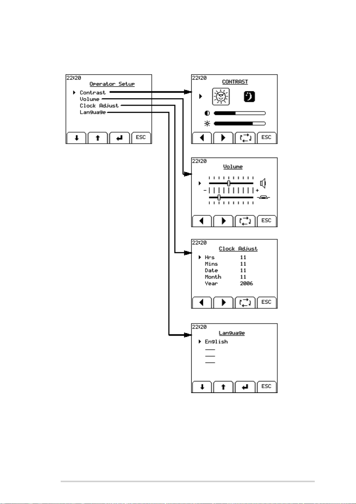
McHale Fusion 3 Baler & Wrapper
7.3.2 Operator Setup Menu
66
Page 67
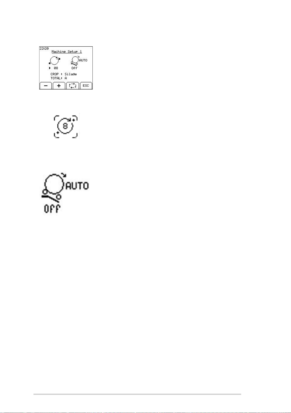
Machine Setup 1
Film Layers
Auto Tip
McHale Fusion 3 Baler & Wrapper
Use the following buttons to navigate the Machine Setup 1:
Toggle key to move the arrow head to each of the
parameters
+ and - keys to change the value of the selected
parameter
ESC to return to the Machine Menu
Film layers are set by the number of ring rotations. Count
the number of rotations required to cover the bale once and
add 0.5 of a rotation, then multiply this resultant figure by
half the number of layers required, e.g. (3.5 + 0.5) x 2 = 8
rotations for four layers. Use the + and - soft keys to adjust
this figure.
Auto Tip can be set on or off. When set to “Off”, the bale will
only be tipped when the bale tip button is pressed (Button
13). When Auto Tip is “On”, the wrapped bale on the
wrapping table will be automatically tipped off when the next
bale is being netted. Pressing the tip button will tip off the
bale earlier, if desired. In automatic mode, the auto tip can
be paused by pressing “tip up” (Button 12), if the conditions
are not suitable to tip off the bale. This stops the bale
transfer cycle after the net is applied. When the machine
has been moved to a suitable tip location then the tip button
can be pressed to a tip the bale and this will also resume the
automatic bale transfer. A small letter “A” will be shown on
the screen under the tip arm to indicate when Auto Tip is
switched on.
Crop
There are three crop options: Straw, Hay and Silage. Use the toggle soft key to move
the arrow head to the crop parameter, then use + and - soft keys to change the crop
type. When set to “Straw” and “Hay” the bales will not be wrapped. The straw setting
has only a one-second delay between the time the bale chamber switch opens and the
net is applied whereas the other options have a three-second delay.
Bale Sub Total
There are ten bale sub totals to choose from (A-J). Using the toggle soft key move the
arrow head to the parameter and then use the + and - soft keys to the change the sub
total.
67
Page 68
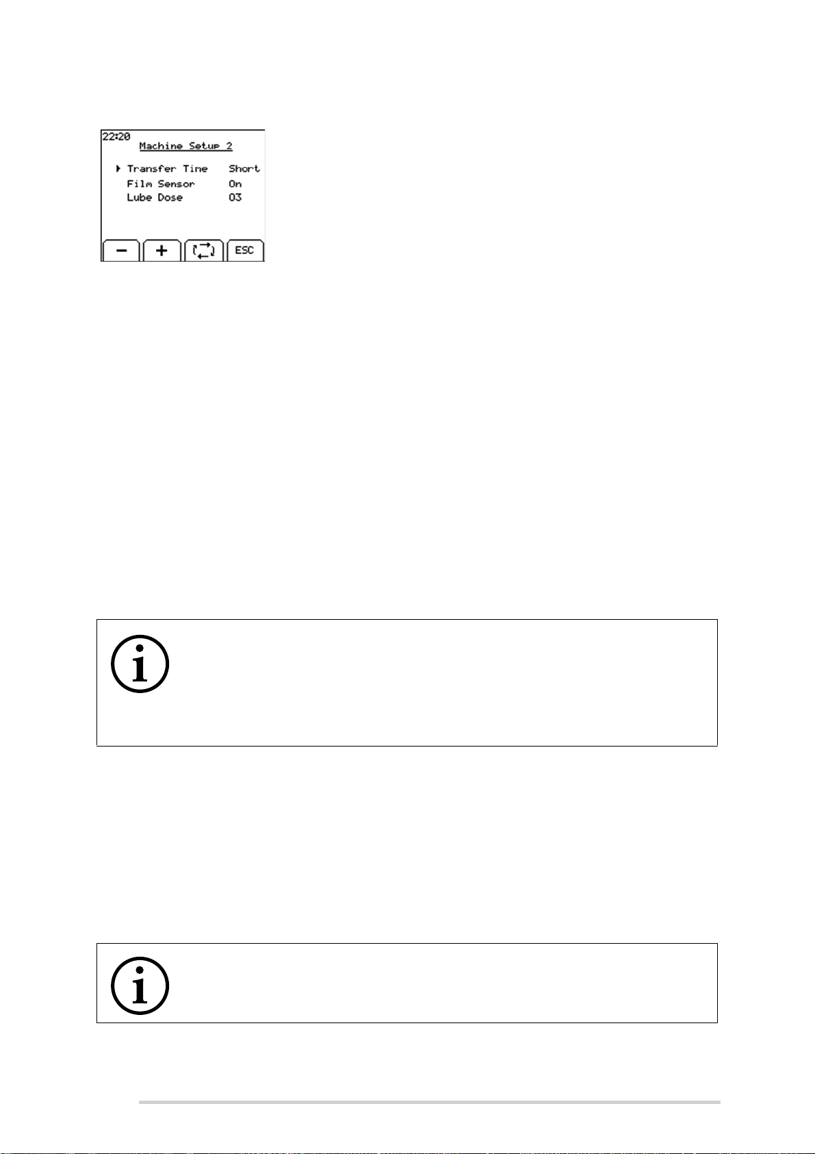
McHale Fusion 3 Baler & Wrapper
Machine Setup 2
Use the following buttons to navigate the Machine Setup 2:
Toggle key to move the arrow head to each of the
parameters
+ and - keys to change the value of the selected
parameter
ESC to return to the Machine Menu
Transfer Time
This setting is the length of time that the chamber door will pause on open, when
transferring a bale from the chamber to the wrapper. There are three options for
transfer time:
1. “Short” will open the door fully and close it again with no pause
2. “Long” will open the door fully and pause on open, for a second, before closing
the door again
3. “Manual transfer” will open the door fully and it will remain open until the
operator presses the “chamber advance” button to continue the cycle. Manual
is only necessary in extremely difficult conditions.
Set this function to “Long” when baling straw, hay or other difficulty to transfer dry
crops. It may also be used when using the baler in difficult conditions, such as hills, but
this will increase the cycle time. Set this function to “Short” for all other baling
conditions.
NOTE: Pause the chamber opening
One press of Button 9 as the chamber is opening will pause the
chamber in the fully open position regardless of the transfer time
setting. Another press of Button 9 will close the chamber and resume
the cycle. This function is useful if facing down a very steep hill and if
the operator is unsure if the bale will transfer properly.
Film Sensor
The film sensor monitors the passage of film through the dispenser rollers. If one
dispenser stops feeding film due to a roll coming to an end, the control box will give an
audible alarm and flash the “1 Dispenser Only” symbol. Bale rotation goes into 50/50
mode, rotating the bale at half speed and the remaining wrapper revolutions will be
doubled, so the correct film coverage will be applied for the remainder of the bale. If the
second dispenser empties, the dispensers will rotate slowly and stop at the loading
position. The control box will display the “Out of Film” symbol and wait.
68
NOTE: The film sensor may be switched off, if desired
The film sensor may be switched off, if desired.
Page 69
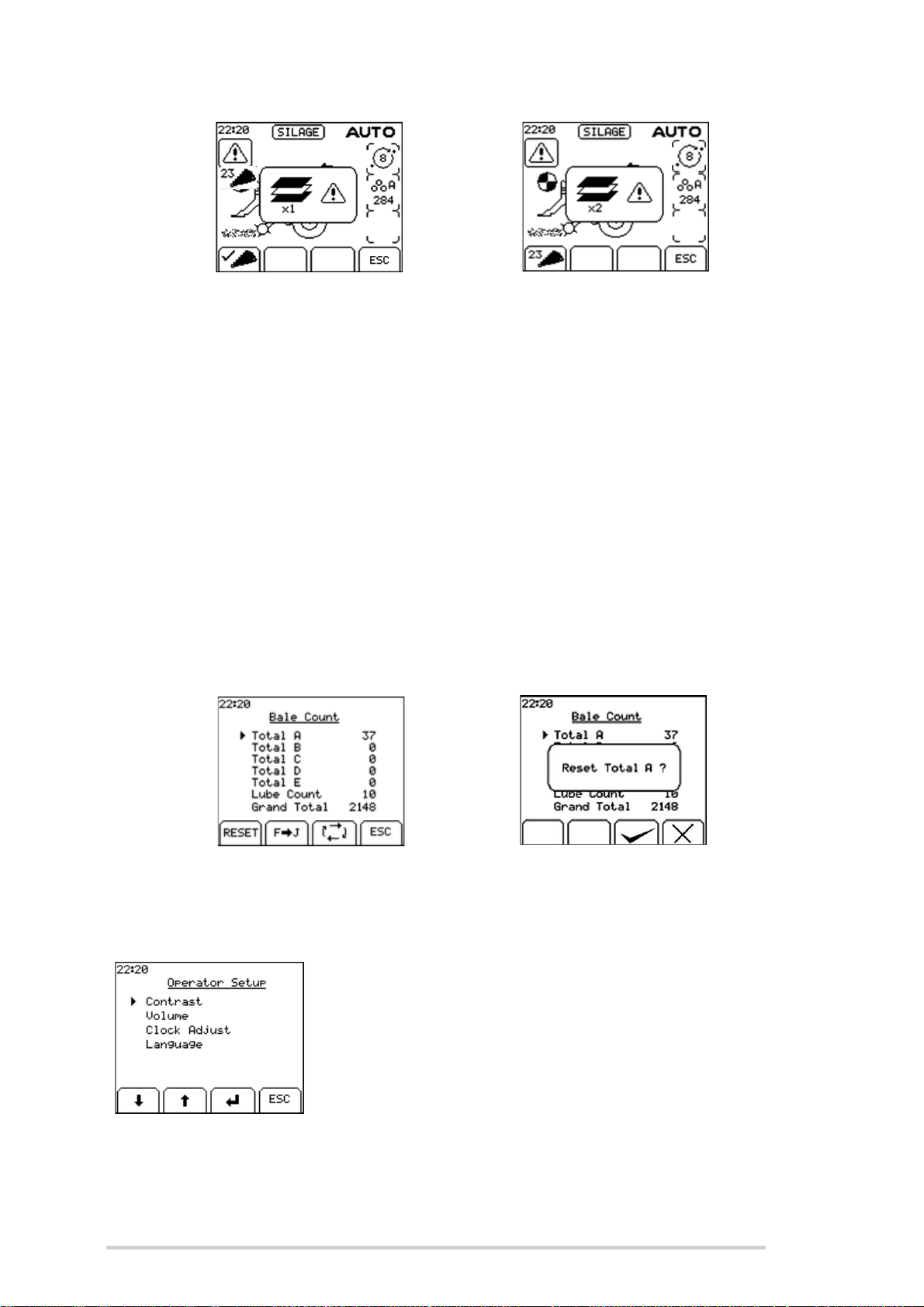
McHale Fusion 3 Baler & Wrapper
1 Dispenser Only Out of Film
Lube Dose
Lube dose is factory set to 3. This should be increased if it is taking a long period of
time to make the bale or in very dry and dusty conditions, as this determines the
amount of lubrication oil applied to the chains. The grease cartridge will also get used
quicker as this setting is also increased, but this is normal and the grease cartridge
does not need to be replaced until the lube alarm sounds every 300 bales.
Bale Count
The bale count menu shows five subtotal bale counts, lube count and the grand total.
The second five subtotals are accessed by pressing the soft key “F-J”. You can return
to the first set of subtotals by pressing the soft key “A-E”.
All subtotals and the lube count can be reset by pressing the reset soft key and the tick
soft key. The grand total cannot be reset.
Bale Count Menu Reset Total A?
Operator Setup
Use the following buttons to navigate the Operator Setup:
Toggle key to move the arrow head to each of the
parameters
+ and - keys to change the value of the selected
parameter
ESC to return to the Machine Menu
69
Page 70
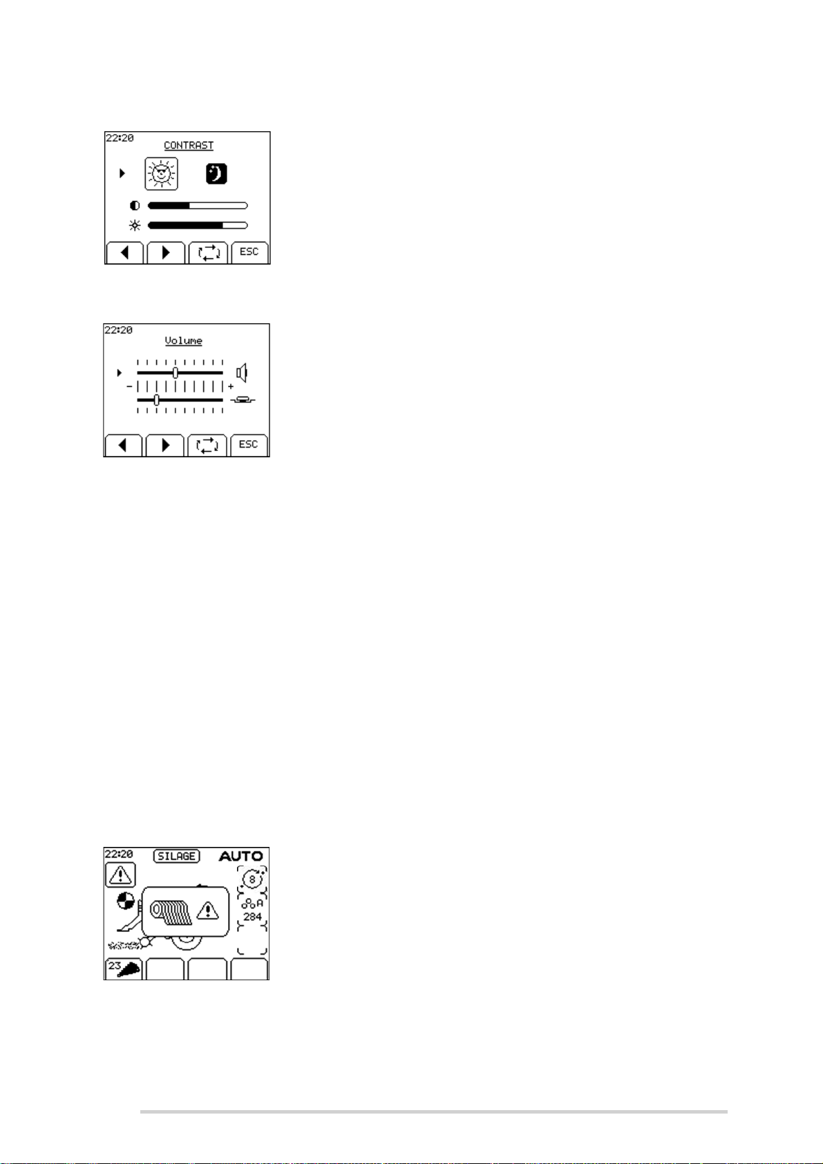
Contrast
Volume
McHale Fusion 3 Baler & Wrapper
Extremes of temperature may affect the contrast of the
display which is adjustable from the contrast menu. Day and
night options are also selectable. The brightness can also
be adjusted.
The volume of the beeper and the button tone can be
adjusted. Use the toggle key to select the beeper/button
tone setting. Use the left arrow head (Soft key A) to
decrease the volume and the right arrow head (Soft key B)
to increase the volume.
Clock
Use the left and right arrow head soft keys to set the time. The toggle soft key moves
from line to line in the menu.
Language
Use the arrow soft keys to move up or down to the required language and press the
enter soft key to select the language.
7.3.1 Technician Menu
The technician menu has a lot of critical settings and is reserved for McHale engineers
only. A pin code needs to be entered to access the menu.
7.4 Warning messages
Check net
The passage of net through the netting unit is monitored. If
the net cutting knife does not trip within 20 seconds of the
netter starting, the net warning is displayed, an alarm
sounds and the cycle is halted.
70
To correct this, complete the following:
Disengage the PTO
Replace the roll of net
Engage the PTO
Press the “Net” button
Page 71
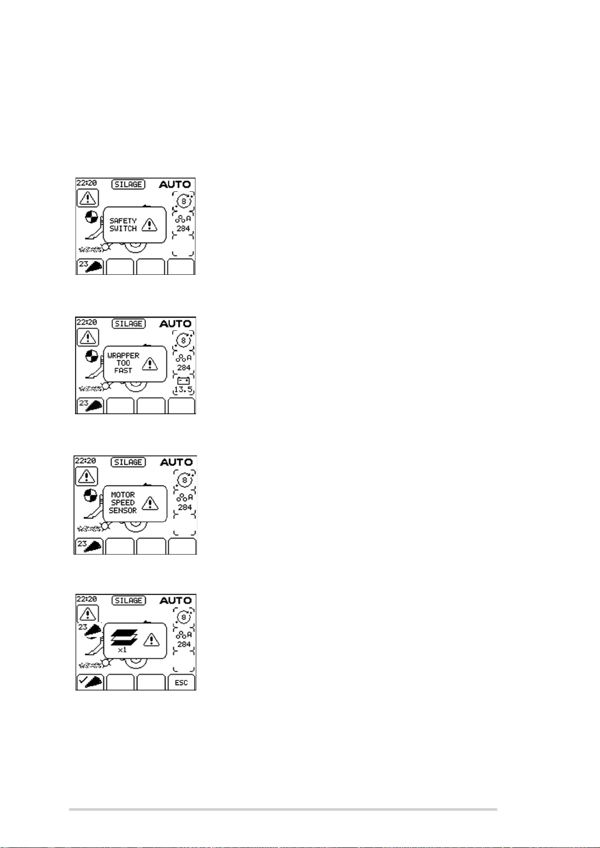
Safety switch
Wrapper too fast
McHale Fusion 3 Baler & Wrapper
The net feeds into the chamber, netting the bale and the
cutting knife trips. The operator then checks that the netting
is complete and advances the cycle by pushing “chamber
door open” (Button 9) for one second, work can then
continue as normal.
A mechanical safety switch on the rear door, where film is
loaded, prevents the dispenser ring rotating if it is open. If
the rear door is not correctly fastened, rotation is prevented
and “Safety Switch!” is displayed.
The cycle can be advanced by pressing “resume” (Button 7)
when the error is corrected.
This warning message will be displayed if the wrapper
speed goes above 35 rpm. Speed is set at 30 rpm from the
factory so this warning will not usually be seen unless the
hydraulic settings have been tampered with.
Motor speed sensor
1 dispenser only
This warning will be shown if pulses are not seen from the
motor speed sensor, once the wrapper ring starts to rotate.
Contact your McHale dealer if you see this.
When the film sensor is switched on, failure of one
dispenser to feed film will flash this warning on the display
and the wrapping rollers will operate in 50/50 mode giving a
correct wrap with the remaining film roll. Press ESC
(Softkey D) to silence the alarm.
71
Page 72
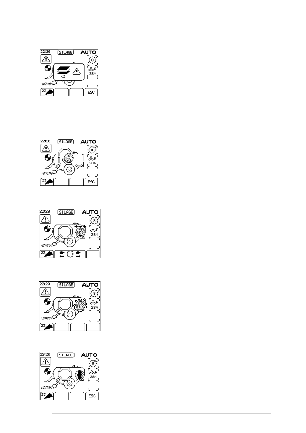
McHale Fusion 3 Baler & Wrapper
Out of film
Transfer not complete
When both film rolls empty, this warning is shown on the
display and the dispenser rotates slowly to the loading
position where the first roll is replaced. The door needs to
be closed, for safety, before the dispenser rotate position is
pushed. This will bring the second dispenser to the loading
position, where the second roll is replaced. The ends of
each roll should be secured in the slots provided, the door
is closed and the cycle is resumed. (See Section “Loading
plastic film” on page 75). Press ESC (Softkey D) to silence
the alarm.
If “Stop” (Button 1) is pushed during the transfer of a bale,
this error is displayed when the control box is next switched
to “Auto”. To correct the error, Button 9 is pushed for one
second to transfer the bale and advance the cycle. Pushing
ESC (Softkey D) on the control box will cancel the error
warning.
Dispenser position
Tip bale
Wrap not complete
If the dispenser ring is not in the home position after netting,
transfer of the bale is prevented and this warning is
displayed. This can be corrected without leaving an “Auto”
cycle, by pushing either forward (Softkey B) or reverse
rotate (Softkey C), as appropriate. When the dispenser ring
is correctly positioned transfer will continue.
This message shows the bale on the wrapper flashing and
prompts the operator to tip off the previous bale on the
wrapping table, which is preventing transfer of the netted
bale. If “Auto tip” is selected, the wrapped bale is
automatically tipped. “Tip Bale” (Button 13) is pushed to
complete the tipping cycle.
72
If “Stop” (Button 1) is pushed during wrapping of a bale, this
error is displayed when the control box is next switched to
“Auto”. To correct the error push “Resume/Re-wrap”
(Button 7) to complete the wrapping cycle. Pushing ESC
(Softkey D) on the control box will cancel the error warning.
Page 73
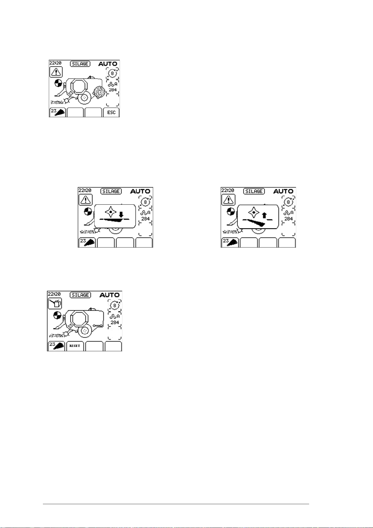
McHale Fusion 3 Baler & Wrapper
Tip not complete
If “Stop” (Button 1) is pushed during the tipping of a bale,
this error is displayed when the control box is next switched
to “Auto”. To correct the error push “Tip Bale” (Button 13) to
complete the tipping cycle. Pushing ESC (Softkey D) on the
control box will cancel the error warning.
Unblock
This is not really an error message but it signifies that unblock is active. A quick push
on “Reset unblock” (Button 10) on the control box will restore everything to a working
condition.
Unblock Reset unblock
Lube count
An alarm is provided to remind the operator to change the
grease cartridge and top up the lubrication oil after a preset
number of cycles. This counts down from 300 and gives a
reminder at zero. Press “Reset” (Button 10) to clear the
warning. It may be reset sooner, if desired, from within the
bale count menu. (See Section “Bale Count” on page 69)
Knife pressure too high
This tells the operator that the hydraulic pressure holding up
the chopping knives is too high for baling which could lead
to knife or machine damage. This warning will be seen if
manually raising the knives with max pressure, (See
Section “Knives Operation” on page 62)
73
Page 74

McHale Fusion 3 Baler & Wrapper
Low voltage
If the voltage drops below 10 volts, then this warning will be
displayed. The usual causes are nearly always either an
inadequate power lead cable or corroded connections.
Ensure the cable connection to euro socket is of good
quality.
7.5 Simulating a “bale to wrapping” cycle
The following procedure is used to test a full “bale to wrapping” cycle, in the absence
of any baling material. It can be used to determine the correct operation for nearly all
equipment, from the start of the baling cycle to the end of the wrapping cycle. The
following is the procedure used:
1. Before starting the tractor, remove the net roll from the netting unit; this is
important! Otherwise net may get tangled up in the netter unit rollers, creating
a mess and wasting net!
2. Turn on the control box and select manual mode, “MAN” will be displayed on
the control box display. (See Section “Control box features” on page 60)
3. Scroll through the control box menu and turn the film sensor to “Off” as in
Section “Film Sensor” on page 68.
4. Turn on PTO at a speed of 540 rpm.
5. While keeping an eye on the bill hook location, near the net set handle, (See
Section “Net cutter setting” on page 41 for details) press “Net feed” (Button 6)
until the bill hook is nearly set to trip (the hook is nearly as high as it will travel
on the knurled wheel before tripping downwards, do not allow to trip)
6. Press “Chamber door open” (Button 9) until the door raises slightly and an
audible beeping sound is heard.
7. Switch the control box to “Automatic” mode. If “Check Net” is displayed in the
control box display, switch the “Manual/Automatic” button twice. This will
ensure tripping of the bill hook.
8. Allow the machine to run its full cycle.
9. Press the “Tip bale” button once, on the control box.
74
NOTE: “Out of film” error
If an “Out of film” error is displayed, this means that step 3 above was not
carried out correctly and the film sensors are set to “On”.
WARNING: Keep out of the “Danger Zone”
Keep all persons outside of the “Danger Zone” during all machine
operations! See “Danger zone” on page 16 for description.
Page 75
McHale Fusion 3 Baler & Wrapper
8
Wrapper Operation
The McHale Fusion 3 is designed with a wrapping system having two plastic film
dispensers. Differing to conventional wrappers, the dispensers move vertically around
the bale. The dispenser carrier system is mounted directly behind the baler chamber.
Although the dispenser carrier ring is well protected by the safety guards and electrical
safety switches, the operator must ensure that all people and animals are kept out of
this region while operating the machine.
WARNING: Keep out of the “Danger Zone”
Keep all persons outside of the “Danger Zone” during all machine
operations! See “Danger zone” on page 16.
ENVIRONMENT: Recycling of the plastic film
Respect the environment! Never throw away or burn the waste plastic
film. Always take waste materials to a recycling centre.
8.1 Loading plastic film
1. The dispenser safety door, on the left hand side of the machine (See Figure
8.a) can be opened by releasing the primary latch (No. 1) with a 13 mm
spanner or flat blade screwdriver and then pushing upwards on the secondary
latch handle (No. 2).
2. Remove the linch pin and release the dispenser film roll lock (See Figure 8.b)
3. Remove the old core and ensure it is disposed of responsibly.
4. Push the new roll on the central pin, engage the film roll lock and reinsert the
linch pin.
5. Thread the film through the dispenser rollers, as per the threading diagram
(See Figure 8.c), taking care not to trap fingers between the rollers.
6. Pull approximately 1.5 m of film away from the dispenser and make a knot at
the end of the plastic film (See Figure 8.d).
7. Close the dispenser safety door.
8. Push the rear mounted dispenser park button, for approx. two seconds, in
order to rotate the next dispenser to the loading or “home” position (See Figure
8.e). The dispenser ring can only rotate when the safety door is closed and the
control box must be in Automatic Mode when depressing this button.
9. Open safety door and load film, as before.
10. Pull approx. 1.5 m of film away from the dispenser and make a knot at the end,
as before.
75
Page 76
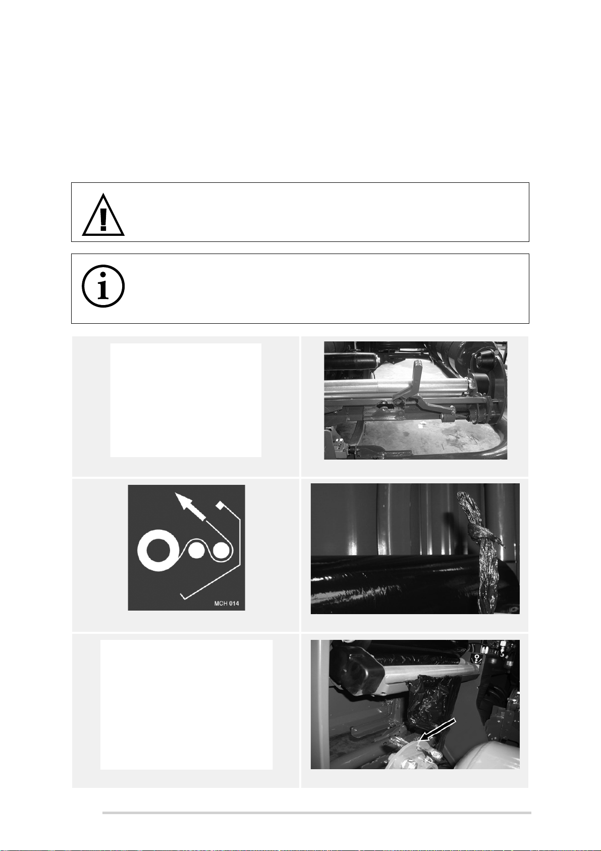
McHale Fusion 3 Baler & Wrapper
11. Slot the knotted end of the film in the left hand side slot of the rear wrapping
roller as shown in Figure 8.f.
12. Grab hold of the dangling film on the right hand dispenser and slot the knotted
end of the film in the right hand side slot of the rear wrapping roller, as shown
in Figure 8.g.
13. Close the door firmly making sure that both primary and secondary latches
have been engaged.
WARNING: Do not clamp film in the “cut & hold” mechanism
Do not attempt to clamp plastic film in the “cut & hold” mechanism as this
action may result in serious injury!
NOTE: Resume a cycle interrupted by “Out of film” error symbol
Pushing the “Resume” on the control box will complete the wrapping
cycle of a bale, that is interrupted by an “Out of film” error symbol shown
in Figure 8.h.
Figure 8.a - Door Latch
Figure 8.c - Film threading diagram
Figure 8.b - Film roll lock (open)
Figure 8.d - Film knot
Figure 8.e - Dispenser Park Button
76
Figure 8.f - L.H.S. Film slot
Page 77
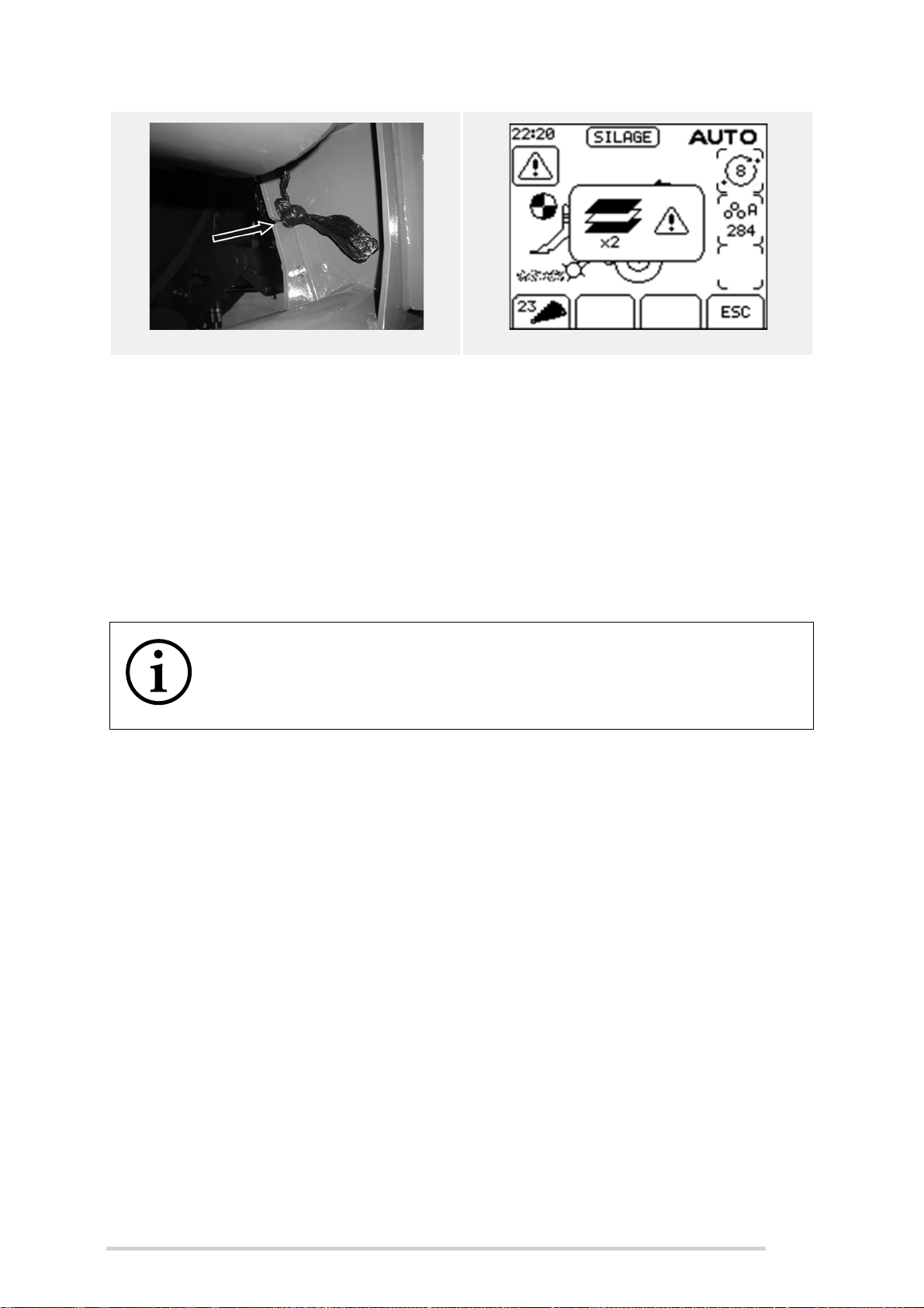
McHale Fusion 3 Baler & Wrapper
Figure 8.g - R.H.S Film slot Figure 8.h - “Out of film”
8.2 Plastic film requirements
Good quality silage depends on the use of top quality plastic film, in addition to well
shaped dense bales. Low standard film material will not produce good silage
regardless of how well the machine wraps the bale. The plastic film should be used and
stored according to the instructions of the film manufacturer.
It is recommended that a minimum of four (4) layers of film be applied to the bale. If the
material being wrapped is of a hard of stemmy nature it may be necessary to apply six
(6) or eight (8) layers to ensure a good airtight package.
NOTE: Operator must check to ensure bales are wrapped correctly
The operator needs to ensure that the bale is wrapped correctly. It is
good practice to check the bales regularly after being wrapped for torn,
split or perforated plastic film.
8.2.1 Determining the number of wrapping ring rotations
To determine the number of wrapping ring rotations required to cover a bale, carry out
the following procedure:
1. Using manual operation, from the control box, manually count the number of
wrapping ring rotations to cover the bale completely with plastic film
2. Add 0.5 to this number
3. Multiply the resultant figure by 2 (for 4 film layers), 3 (for 6 film layers), 4 (for 8
layers), 5 (for 10 layers), etc.
4. Round up to the next full number if the result contains a fraction of a full
number.
Example:
Number of “Wrapping ring rotations” to cover bale: 3.5 = (x)
Number of rotations to apply 4 layers of film to bale = (3.5 + 0.5) x 2 = 8
Important Notes:
(x) “Wrapping ring rotation” = both dispensers rotating 360° around the bale.
77
Page 78
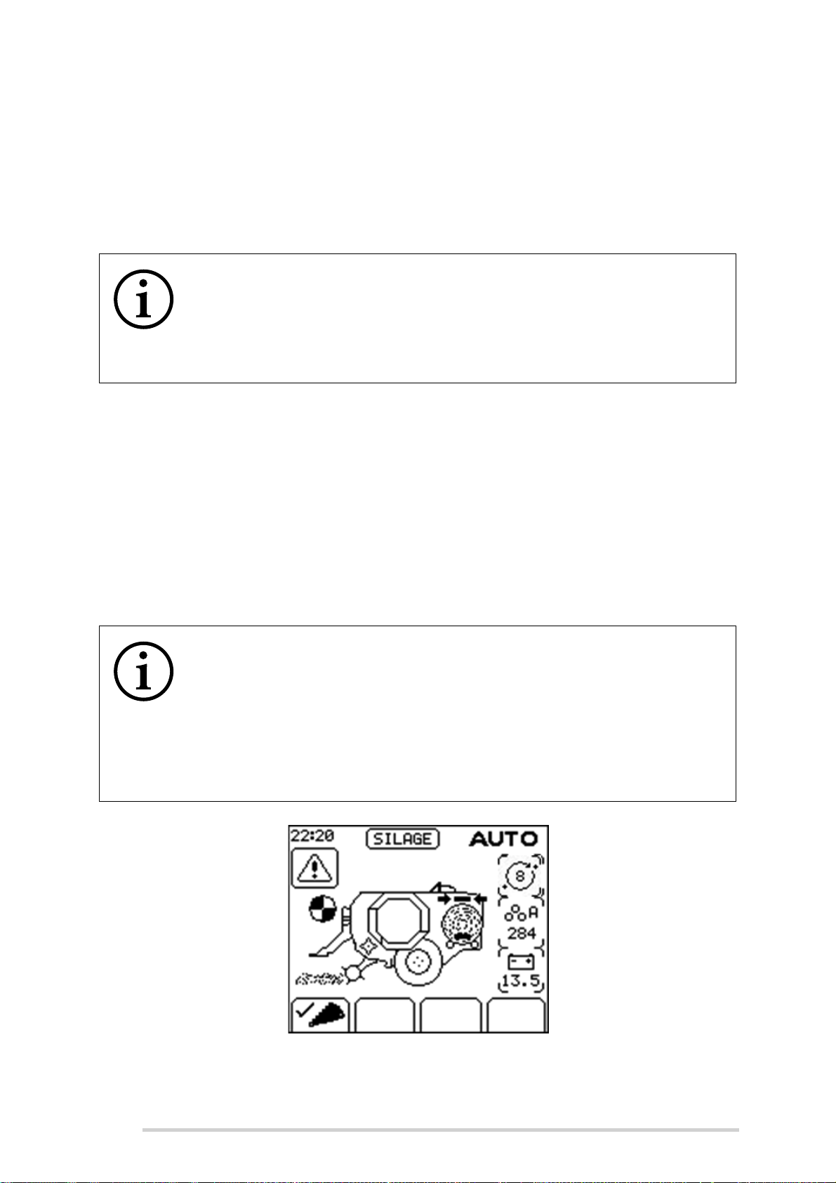
McHale Fusion 3 Baler & Wrapper
The McHale Fusion 3 is a fixed chamber baler with the bale diameter usually
1230 mm - 1270 mm. However, bales in excess of 1270 mm, can be
produced if any of the following conditions exist:
(a) If not enough net has been applied to the bale (especially in high dry
matter material)
(b) Excessive feeding of the bale chamber, not allowing the bale to be
properly compacted to its correct size.
NOTE: Check bale diameter for enough wrapping ring rotations
It is very important to note that bales in excess of 1300 mm will not have
enough “wrapping ring rotations” if the above exercise has been carried
out on a normal 1250 mm bale. Therefore, it is important to check the
bale diameter at every change in crop condition or in differing crop row
widths and densities.
8.3 Wrapping process
The wrapping process starts automatically as soon as the bale has been transferred
from the bale chamber to the wrapping table (chamber door closed, rear roller in fully
raised position and the access door closed). After the bale is wrapped with the selected
number of film layers, two (2) cut & hold units grip and cut the film. The wrapping cycle
is completed and the bale is ready for discharging.
If “Auto Tip” is selected, the wrapped bale is discharged when netting of the next bale
starts.
NOTE: Bale will not transfer if dispenser ring is in wrong position
The bale will not transfer from the baler chamber if the dispenser ring is
in the wrong position. This is a safety feature and is normal. In this case
and audible alarm will sound and the “Dispenser Position” error symbol
will be displayed in the control box display. The forward and reverse soft
key indicators will become active on the control box. Press the
appropriate button in order to correct and once corrected the bale will
transfer and the wrapping cycle will begin.
78
Figure 8.i - Dispenser position error symbol
Page 79
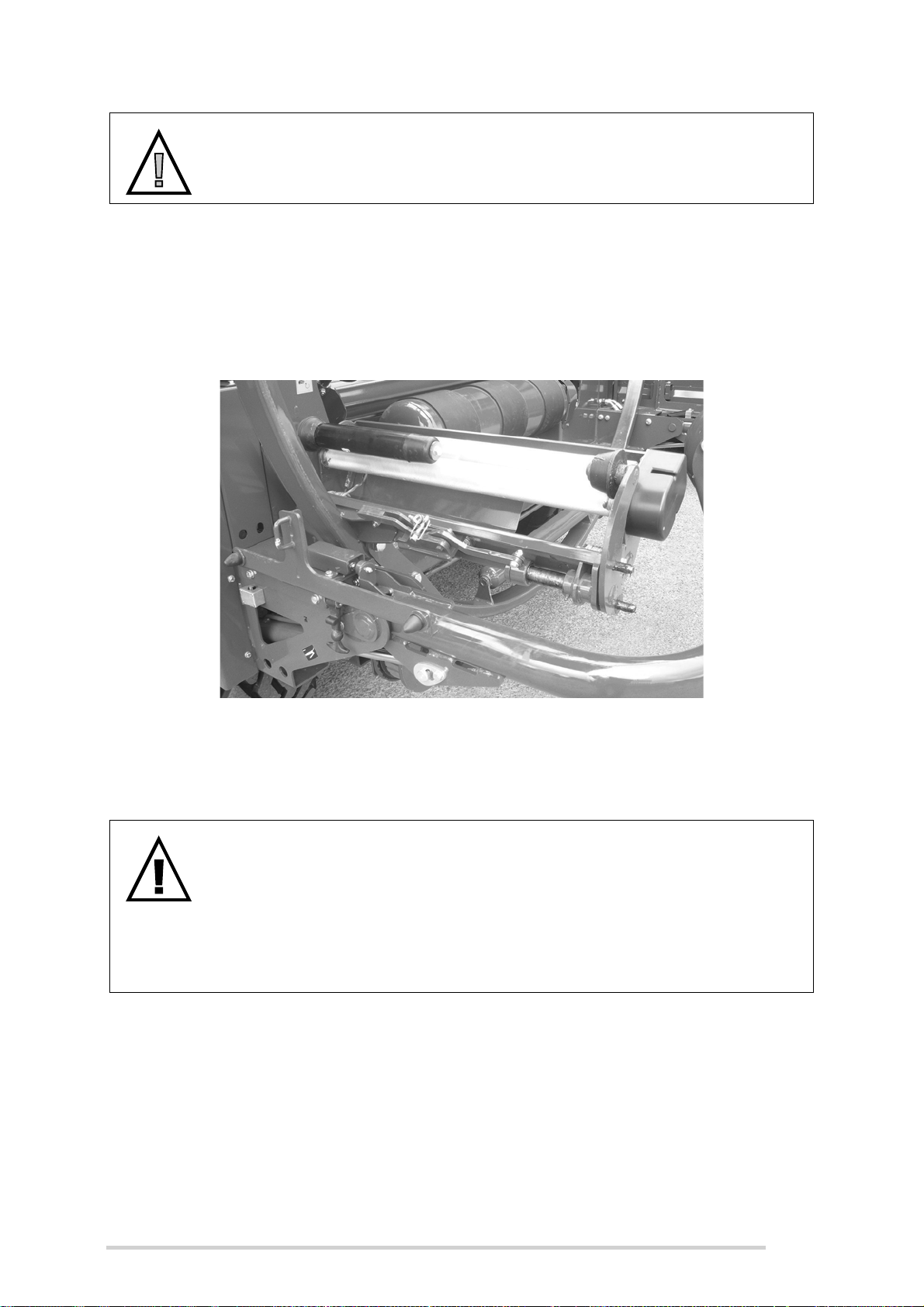
McHale Fusion 3 Baler & Wrapper
l
CAUTION: Do not tip off bales while moving
The machine should not be moving when the bale is tipped off, as this
greatly increases the risk of plastic film damage.
8.4 Dispenser adjustment
The dispenser rollers are set for a standard film stretch of 70%. Optional sets of
dispenser gears for both 55% and 64% film stretching are available from your McHale
dealer.
Figure 8.j - Dispenser in the “home” position
8.5 Cut and hold system
WARNING: Beware of knives & accumulators during maintenance
The cut and hold system utilises knives and accumulators in order to
function. Beware of serious injury when carrying out any maintenance in
this area. Turn off the tractor and remove the key from the ignition. Wear
protective gloves and clothing, at all times! Also, never carry out any
work on the hydraulic hosing because even when the machine is off,
hosing remains under high pressure due to the accumulators.
The cut and hold system on the McHale Fusion 3 is designed to operate in conjunction
with both the dispenser and table rollers to cut the plastic after a desired amount of film
wrap has been applied to the bale, as set on the control box. See previous sections, for
more information on the wrapping process. The cut and hold system operates by way
of a slider (D) that slides in and out using a hydraulic ram. The slider (D) then clasps
the film and retracts to hold the film between (C) and (D) which is then cut at knife point
(B). Once the wrapping process resumes, the film is then released.
79
Page 80
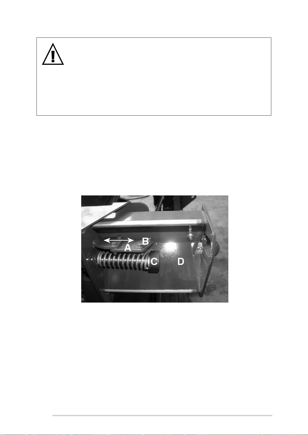
McHale Fusion 3 Baler & Wrapper
WARNING: Beware of knives & accumulators during maintenance
Before working on cut and hold rails, always release the hydraulic
pressure from accumulators by wrapping the spanner and hose-fitting
with a cloth, then slowly and carefully open the pressure hose fitting (See
figure 8.k), allowing oil to release before re-tightening. Accumulator
pressure will reset automatically following the first operation of the cut
and hold cylinder in the fully out direction.
Never work on the cut & hold by holding out the rails against hydraulic
pressure.
The cut and hold knife may be adjusted in and out by following the procedure below
and by referring to Figure 8.k:
1. Remove the two M6 nyloc nuts and bolts that hold knife plate (A) using 10 mm
spanners. Beware of the cutting knife!
2. Move the knife plate to the desired position. The factory setting is to the fully
out position, as shown.
3. Insert the two M6 bolts and tighten nyloc nuts to 12 Nm.
4. Repeat for the other cut and hold.
Figure 8.k - Cut and hold knife adjustment and removal
The cut and hold knife blade condition is very important for the proper operation of the
cut and hold system. A blunt blade may not cut the film cleanly or possibly not at all. As
such, the knives must be changed under part number CKN00011. Ensure all safety
precautions are taken before carrying out the procedure on the following page.
Change the cut and hold knives by following the procedure and referring to Figure 8.k:
1. Loosen the two M6 setscrews that hold the knife clamp plate (B) in place using
a 10 mm spanner or socket, beware of knife blade!
2. Remove used knife, noting that there is a spare knife blade held by the bottom
of the knife clamp plate (B).
80
Page 81
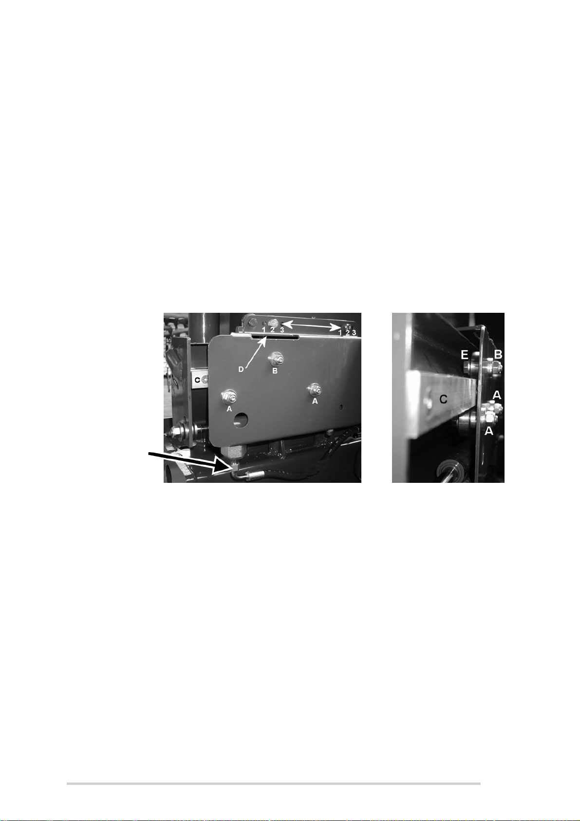
McHale Fusion 3 Baler & Wrapper
Accumulator
Pressure
Hose
3. Place spare knife in the working position and place a new spare knife
underneath, if available.
4. Tighten the two M6 setscrews to 12 Nm.
Cut and hold rail adjustment
After much use, the moving part of the cut and hold rail (C) may develop wear. In such
a case this may be adjusted, to ensure optimum working of the cut and hold. While
referring to Figure 8.l, adjust as follows:
1. Insert a 24 mm open ended spanner into slot (D) until it engages with the
hexagon on adjuster cam (E).
2. Loosen M12 nyloc nut (B) on adjuster slightly, just enough to be able to turn
adjuster (which works on a cam principle).
3. Turn adjuster (preferably clockwise from cam side E), with a 24 mm spanner,
until the resistance to turning increases greatly.
4. Hold resistive pressure on the adjuster cam (E) and tighten the M12 nyloc nut.
Figure 8.l - Cut and hold rail/horizontal position adjustment
Cut and hold horizontal position adjustment
The cut and hold assembly can be adjusted through three (3) different horizontal
positions, if desired. The factory set position is position 2 as shown in Figure 8.l. Ensure
that cut and hold assembly is safely secured (as assembly is quite heavy) before
attempting the following procedure:
1. Loosen and remove the four M12 x 40 mm bolts and 12 mm spacers and
carefully reposition bolts into the desired position i.e. 1, 2 or 3.
2. Place 12 mm spacers between cut and hold assembly and the main chassis,
then tighten M12 nyloc nuts to a torque value, as described in Section
“Tightening torque values” on page 108.
81
Page 82
McHale Fusion 3 Baler & Wrapper
9
Road Traffic Safety & Operation
9.1 Before travelling on any public roadway
WARNING: Complete a full inspection before travelling on the road
Ensure that a full inspection is completed every time before attempting
to go on to a public roadway, always think and practice safety!
The following should be inspected every time, before travelling on a public road:
Ensure that the tyres are set to the correct pressure as per safety decals and
according to the specifications, as outlined in Section “Tyre specifications” on
page 13.
Ensure that all doors are securely closed and fastened, ensuring that primary
and secondary catches are fully engaged, these should be kept clear of
foreign objects to ensure proper and trouble free operation.
The bale forming chamber should be emptied and there must be no bale on
the wrapping table.
The machine must be safely cleared of all loose forage. To carry this out,
firstly turn off the tractor and fully isolate the machine by disconnecting all of
the connections to the tractor unit.
The PTO shaft must be fixed safely to the tractor PTO stub shaft.
The lighting system of the machine must be connected to the tractor and must
be in a fully functioning condition.
The electronic control box must be switched off or disconnected from the
power supply, see section “Control box functions” on page 59.
The hydraulic supply must be turned off and protected from accidental
activation by disconnecting the hydraulic feed line. Support all loose lines in a
safe manner.
The pick-up guide wheels must be fixed in the road transport position (See
Figure 9.a) and the drawbar/PTO stands secured in a working position, see
section “Drawbar and PTO shaft stand usage” on page 52.
Attention must be paid to the maximum travel speed-limit (40 km/hr) printed
on the chassis plate, on the left hand side of the machine. Other speed limits
that may be printed, on the drawbar plate or axle plate, for example are not
relevant.
82
Page 83
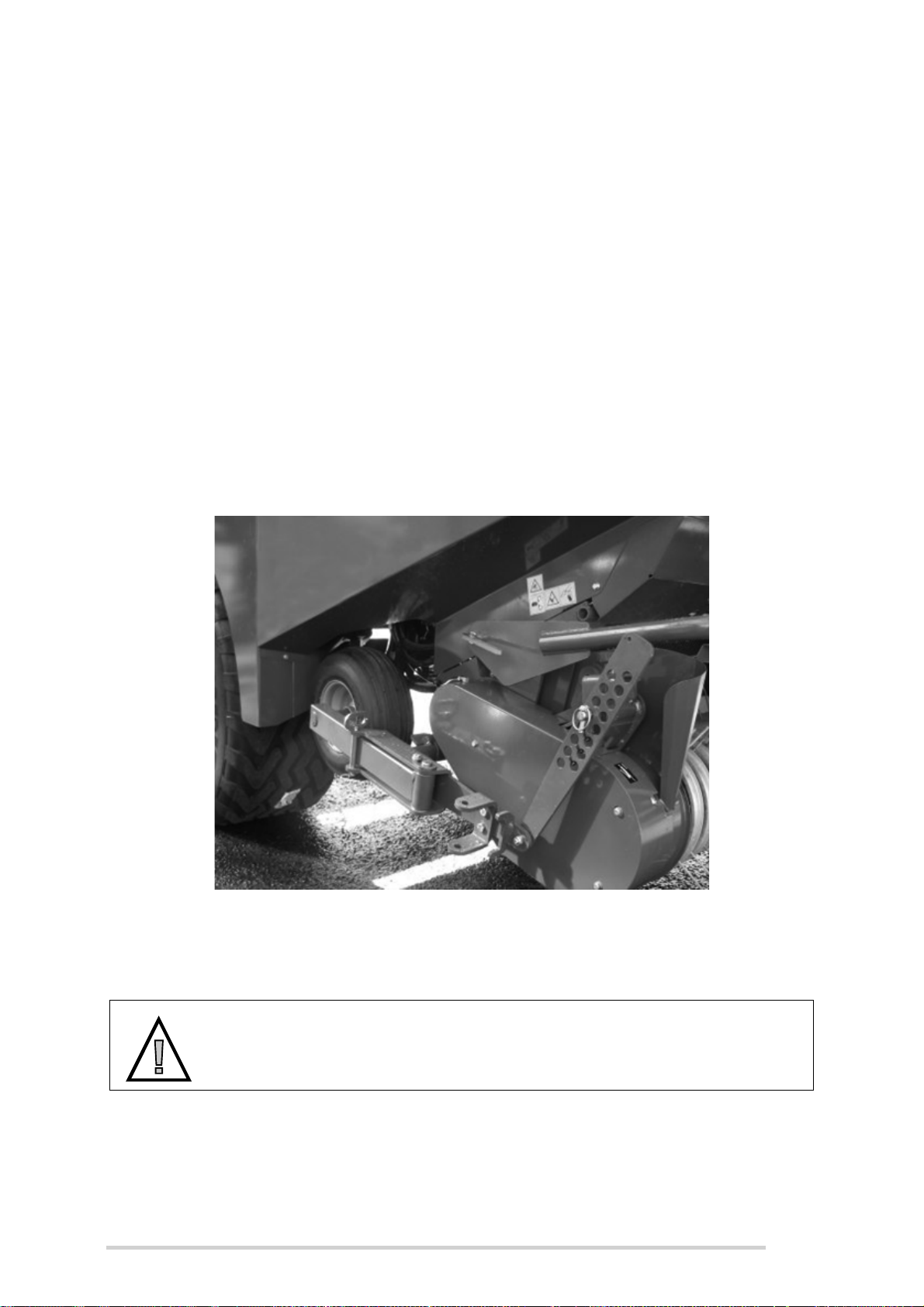
McHale Fusion 3 Baler & Wrapper
The brake system of the machine (hydraulic or pressurised air) must be
connected to the tractor. Do not travel, with air brakes, until the required
pressure is shown on the indicator of the tractor panel.
Ensure that all the national road traffic regulations relating to the country are
fulfilled i.e. the use of safety chains may be mandatory in certain countries.
9.2 Road transportation
Close and secure all doors and panels.
Empty the baling chamber and the wrapping table.
Clear the machine of loose forage.
Lift the pickup reel completely and close lever on hydraulic line (if fitted).
Unlock the pick-up guide wheels and swing them backwards into the transport
position, and lock them carefully.
Figure 9.a - Road transport position
9.3 Road transportation with side tip attached
CAUTION: Side tip is not to be used on public roadways!
Side tip is not to be used on public roadways!
Beware of projection distance to the rear of the machine, when reversing, a
side tip attachment greatly increases the length of the machine. See serial
plate for details.
83
Page 84
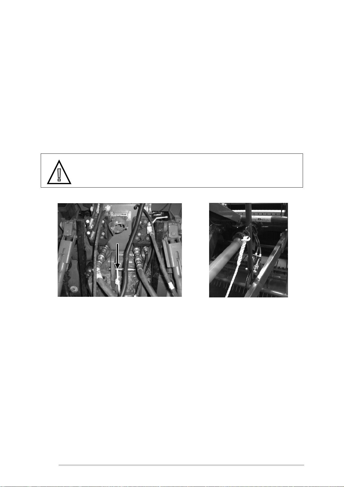
McHale Fusion 3 Baler & Wrapper
Break-away rope
Do not attempt to go over 20 km/h at any time, while the side tip attachment is
assembled to the machine.
See Section “Side tip” on page 102 for more details on the Side tip
attachment.
9.4 ‘Break-away’ brake
The McHale Fusion 3 is fitted with a handbrake which must be applied when the
machine is detached from the tractor. The handbrake handle has a rope fitted to a
calibrated ring which must have the other end securely fixed to the tractor, each time
the Fusion 3 is attached to the tractor. If the Fusion 3 hitch ever becomes detached
from the tractor this rope will apply the brakes on the Fusion 3.
CAUTION: Ensure the hand brake is released when moving
Always ensure that the hand brake has been released before moving the
Fusion 3 on the road or operating in a field.
Figure 9.b - Break away rope fixed to tractor
84
Figure 9.c - Handbrake handle
Page 85
McHale Fusion 3 Baler & Wrapper
10
Field Operation & Baler Adjustments
10.1 Break-in period
McHale recommend an break-in period of approximately the first 50 bales or until the
paint within the baler has lost its shine.
NOTE: Making bales greater than the maximum diameter is not
recommended on a frequent basis
It is important to realise that roller and drive loads increase as the bale
size approaches its’ maximum diameter. As such, frequently making
bales greater than the maximum diameter, by pressing and holding the
net button on the control box, is not recommended as this can lead to
premature failure of components. Ensure that all grease points are
adequately greased to prevent rapid wear of components.
10.2 Swath preparation
An optimum baler performance of the McHale Fusion 3 requires a good swath
preparation in advance. The optimum swath width is 1.5 m.
NOTE: Swath width is the most important factor in proper bale
formation
A 1.5 m swath width provides optimum material flow into the bale
chamber for even bale formation. A swath width greater or less than
1.5 m will lead to increased bale deformation.
In the case where narrower swaths are unavoidable, it is recommended that the swath
be periodically directed 30-40 m to the right hand side and also the same distance to
the left hand side of the pick-up as the baler is driven over the swath, see Figure 10.a.
Collect the material into one side of the pick-up for 6 to 8 seconds. Then cross over the
windrow and collect material for the same duration. Reduce the length of time for heavy
windrows and increase for lighter windrows.
Continuous weaving is not recommended as this will result in excessive material being
placed towards the centre of the bale, see Figure 10.a.
In the case of wider swaths, i.e. >1.5 m; this size of windrow should be avoided, as in
this case a greater amount of material will continue to be fed to the outside of the baler.
85
Page 86
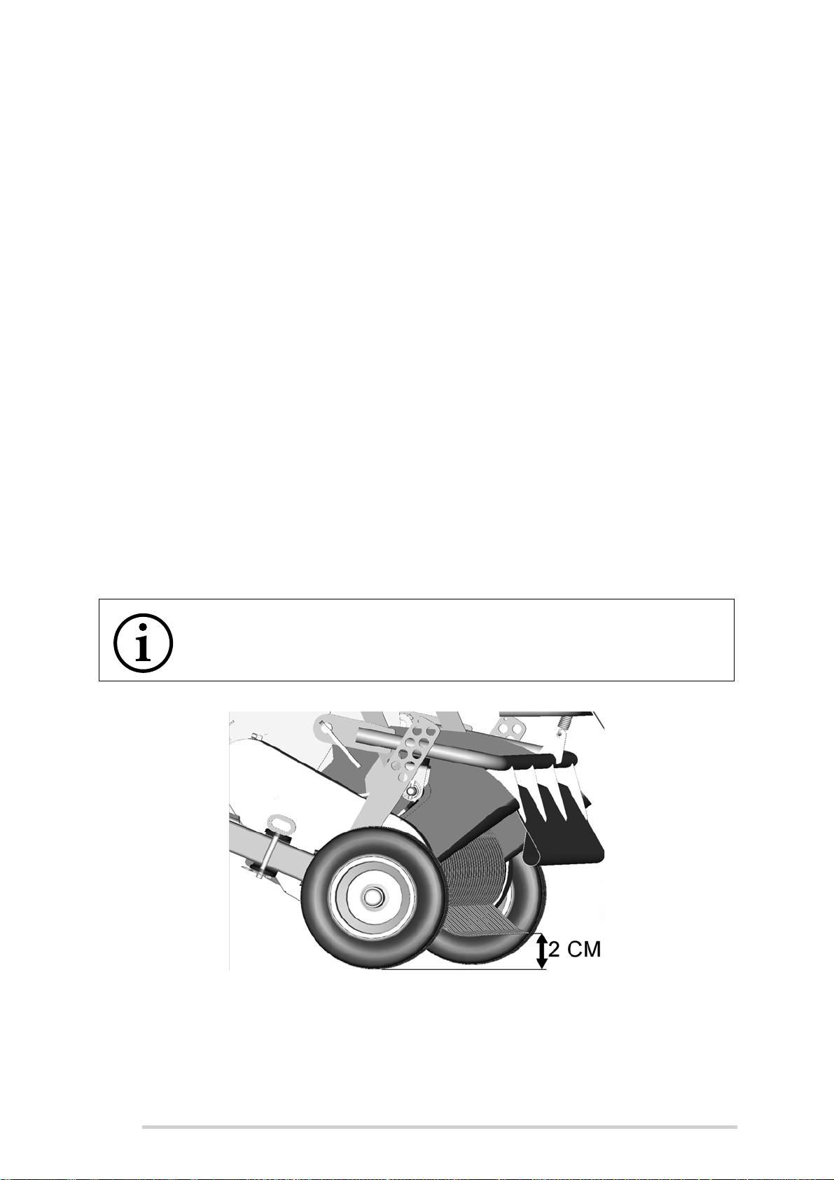
McHale Fusion 3 Baler & Wrapper
As a result, a greater amount of material will be fed to the outer edges of the bale than
to the centre. This will result in concave-shaped bales.
Figure 10.a - Swath widths - correct & incorrect
10.3 Pick-up reel height adjustment
Before working in the field unlock and swing the pickup guide wheels forwards and lock
them again carefully. Use the appropriate hole in the adjusting bar so that the pickup is
balanced and at the optimum working height with the pick-up tines being 2 cm above
the ground.
NOTE: Wear and tear of pick-up tines
Working with the pick-up tines set too low will leave them susceptible to
breakage and rapid wear!
86
Figure 10.b - Pickup adjustment
Page 87
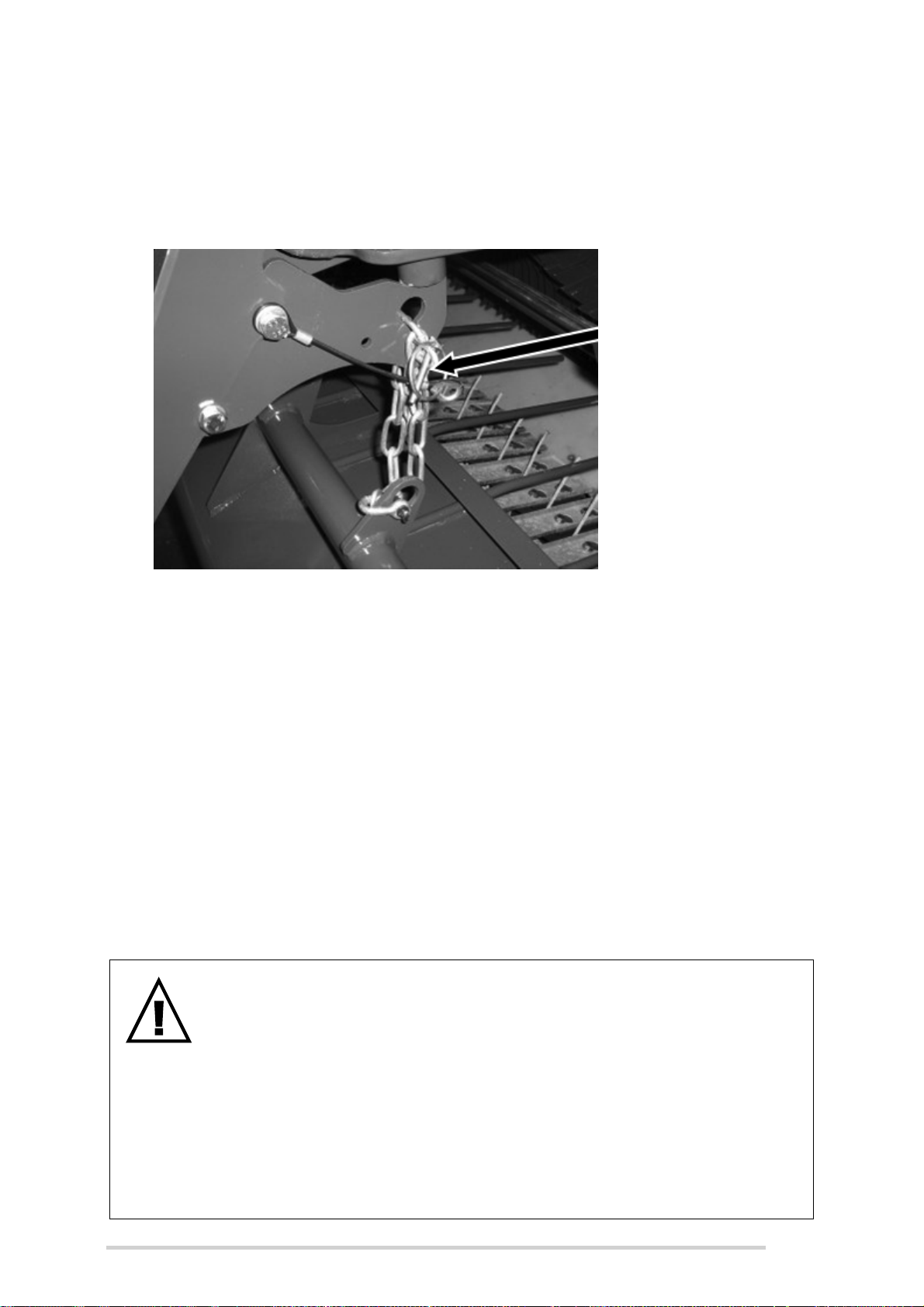
McHale Fusion 3 Baler & Wrapper
Crop guard
adjustment chain &
plate
10.4 Crop guard adjustment
The function of the crop guard plate is to hold down the baling material in order to
achieve an even flow of material. The height of the crop guard place can be adjusted
to suit the material type and volume, by means of adjusting the chain length.
Figure 10.c - Crop guard adjustment chain
10.5 Unblocking system
The McHale Fusion 3 is equipped with an unblock system. In the case of a blockage
in the feeding channel, the PTO overload clutch will disengage and a loud clicking
noise will be heard. Once this sound is heard, immediately turn off the tractor PTO and
push “Unblock” (Button 11) on the control box for three seconds, while in the Automatic
cycle. This will start the unblock routine and the knives, if set to ON, (see Section
“Electronic Control System” on page 58) will retract along with the channel floor. Then
restart the tractor PTO at a slow speed, increasing speed slowly up to 540 rpm and not
exceeding 610 rpm. Any lumps of material will now be easily transported into the bale
chamber.
After having cleared the blockage, a quick push of “reset” (Button 10) will return the
channel floor to the working position, followed by the knives, if previously set to ON.
WARNING: Never go near the pick-up reel, while the reel is still
rotating and the tractor is running!
Never attempt to go near the pick-up reel while the reel is still rotating
and the tractor is running. In the rare case that the reel cannot be
unblocked using the procedure above, then the pickup reel will require
manual unblocking, by removing the excess blocked material. To do this
safely ensure the PTO is disengaged, tractor shut down, key removed
and that all parts have stopped rotating. Also ensure machinery can’t roll
by parking machinery on level ground with the brakes applied and
wheels chocked. Remove excess material carefully. Always wear
protective clothing and gloves, beware of sharp edges!
87
Page 88
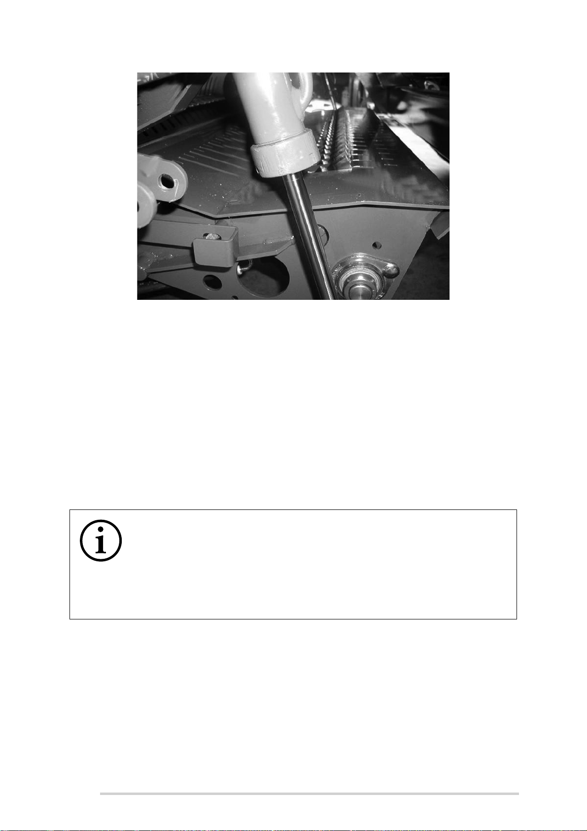
McHale Fusion 3 Baler & Wrapper
Figure 10.d - Unblock mode, knives retracted and channel floor lowered
10.6 Chopping system
The McHale Fusion 3 is equipped with a 23 knife chopping system for fine cutting. If
a coarser chop is required 11 of the knives can be removed, or all of the knives can be
removed, if desired, see “Chopper unit knife removal & installation” on page 43. The
knife buttons on the control box will move the knives into the feeding channel or retract
them. It is recommended to switch the chopping device off when baling very dry
material.
In order to protect the chopping device against overload and damage, hydraulic
accumulators are connected to the actuation circuit.
NOTE: Keep the knife slots clear of material
To keep the knife slots clear of material, it is recommended to switch the
knives on and off several times daily. To do this, press “knife selection”
once (Softkey A), while the control box is in automatic mode. This will
move the knives to the opposite position. One more press will move the
knives back to the original position. See “Knives Operation” on page 62
for proper control unit operation of the knives.
10.7 Selectable knives
Selectable knives are available as an option on the McHale Fusion 3 Baler & Wrapper.
The operator can select between 0, 11, 12 or 23 knives from the control box. The knives
must be fully down, before selecting the desired set of knives. See Section “Knives
Operation” on page 62.
88
Page 89

McHale Fusion 3 Baler & Wrapper
Figure 10.e - Selectable knives
10.8 Bale density gauge
The bale density gauge, is used to indicate the pressure
applied to the top door rams (on the small side of the rams).
When the top door is closed, and no material in the baling
chamber, this is known as “chamber pre-charge pressure”.
This pressure will then increase at the end of the bale
forming cycle, due to the oil in the cylinders being forced
into the accumulator. As material begins to fill up the baling
chamber, it pushes the door rams open ever so slightly.
This can cause the gauge to go into the red and this is
normal operation. However, pressure should never go
above 200 bar, if it does consult your McHale dealer.
10.9 Setting chamber pre-charge pressure
The bale density gauge is divided up into increments of 20
bar per increment and has a yellow zone, green zone and a
red zone, as a quick reference during machine operation.
When baling drier materials, such as straw or hay, McHale
recommend setting the chamber pre-charge pressure
between 70 and 110 bar pressure. When baling wetter
materials, such as grass for silage, a pressure of between
110 and 160 bar is recommended.
CAUTION: Never adjust chamber pre-charge pressure above 160
bar
The chamber pre-charge pressure should never be adjusted above 160
bar pressure in any case, damage to machine components may result!
Chamber pre-charge pressure is set at the door charge valve, shown above and is
located in the hydraulic section (inside the front right door panel), by following the below
procedure:
89
Page 90

McHale Fusion 3 Baler & Wrapper
1. Remove all unfinished and finished bales from the baling chamber
2. Loosen the lock nut on the adjustment screw (A)
3. Inspect the existing pre-charge pressure by holding the “Top door close”
(Button 8), while in Manual mode, on the control box for 3 seconds, see
“Control box functions” on page 59.
4. If pressure must be increased (gauge in the yellow zone, or if there is a change
in the material being baled, i.e. dry to wet, etc. gauge in the green zone) turn
the adjustment screw (A) clockwise and if the pressure is to be decreased turn
the adjustment screw anti-clockwise.
5. Continue to inspect the gauge and once the indicator needle is at the desired
setting, tighten the lock nut on the adjustment screw ensuring not to let the
adjustment screw itself rotate and close all protective covers. To reduce the
pressure the door must be opened, then turn the adjustment screw and close
the door again to check the gauge.
Grass-Silage or Hay-Straw adjustment (located behind the hydraulic section, on the
non-drive side of the chamber, inside the front right hand door of the machine). The
bale chamber features a quick adjustment sensor position plate. This allows for a quick
change to lower density bales as required for hay and straw without any need to adjust
the chamber pre-charge pressure. In effect, it limits the level to which the chamber
pressure will climb above the pre-charge pressure during baling of hay and straw.
Figure 10.f - Grass & Silage position
(Handle left)
Figure 10.h - Hay/Straw (Handle right) Grass/Silage (Handle left)
Figure 10.g - Hay & Straw position
(Handle right)
90
Page 91
McHale Fusion 3 Baler & Wrapper
To lock, rotate lever (A) down
90° to the vertical position
10.10 Chamber door lock
The chamber door lock is to be used at all times that the operator may wish to enter the
chamber in order to change the cutter knives for example. The lock is located in the
front right hand side panel of the machine. See below for the safety decal and location
of the chamber door lock valve. The lock works by way of a hydraulic on/off valve, while
locked the valve is in the “off” (vertical) position and the hydraulic rams will remain
locked open, securing the door in a fixed position.
WARNING: The operator must be aware of all related warnings,
safety decals and dangers
The operator must be aware of all related warnings, safety decals and
dangers before attempting to carry out any work or maintenance from
within the baling chamber. Please refer to and follow carefully “Chopper
unit knife removal & installation” on page 43 for instructions on how to
enter the baling chamber.
Figure 10.i - Chamber door lock Figure 10.j - Chamber door lock decal
10.11 Spare film holders & door latch safety
The McHale Fusion 3 can hold up to 10 rolls of spare film along with 1 more in each
of the two dispensers. The spare rolls are stored at each side of the machine, behind
the front panels. To open the primary latch (No. 1) on the door panels, a 13 mm
spanner or flat blade screwdriver will be required. The secondary latch (No. 2) is
opened by pushing it inwards to release the panel. (See Figure 10.k)
To store film rolls carefully, pull down film holders and slide the film roll core onto the
film holder. Each holder stores two rolls of film each. Push the film rolls back into an
upright position.
.
WARNING: Beware of falling stored objects behind door panels
Beware of falling plastic film rolls and other stored objects when
opening door panels, especially when the machine is not on level
ground!
91
Page 92

McHale Fusion 3 Baler & Wrapper
Figure 10.k - Safety latch types
10.12 Adjusting pick-up float springs
The spring retained collars which are used to adjust the pickup float springs are located
on either side, underneath the chopper unit, see Figure 10.I below. To adjust, follow the
procedure below:
1. Using the tractor spool handle, hydraulically raise the pickup, in order to
release float spring pressure.
2. Ensure that the tractor engine has been shut down, the key removed and the
brakes applied before carrying out the following procedure.
3. Loosen the collar by slacking off the bolts (circled in Figure 10.l), then tap the
collar in the direction (R), If increased float is required, or in direction (F), if less
float is required.
4. Remember to fully tighten the bolts on the collar when adjustment is complete
and lower the pickup reel.
.
NOTE: Adjustment should enable the pickup to drop completely
This adjustment should enable the pickup to drop completely, while in
the lowered position. If not, re-adjust by lowering the spring tension, i.e.
move the collar in direction (F).
92
NOTE: Additional spring force required when operating at heights
If operating at heights other than the fully lowered position, then
additional spring force will be required to obtain adequate float, i.e. move
the collar in direction (R).
Page 93
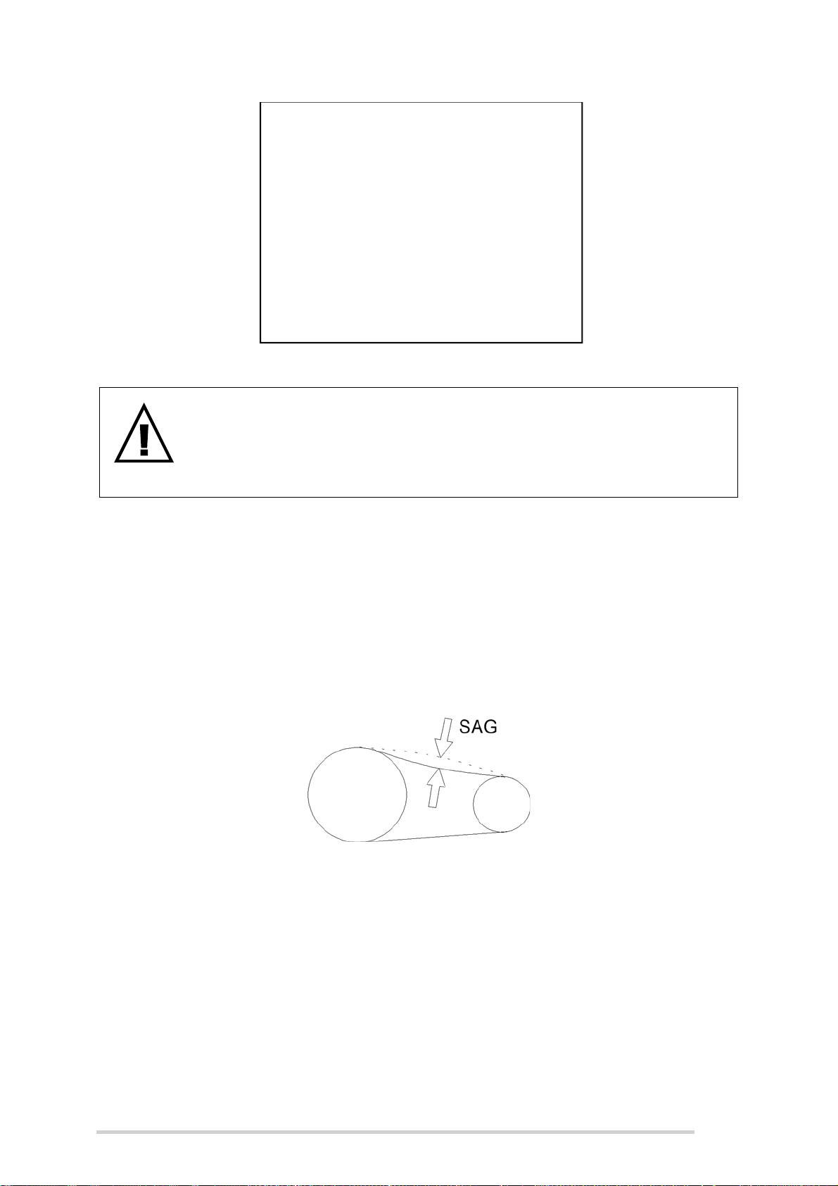
McHale Fusion 3 Baler & Wrapper
F
R
Figure 10.l - Adjustment of pickup float springs
WARNING: Ensure spool control lever is in the “float” position
When baling with the McHale Fusion 3, ensure that the control lever for
the spool operating the pick-up reel height adjustment is in the “float”
position. If the lever is not in the float position, then the reel will be fixed
in a set position and unable to follow the ground contour.
10.13 Chain adjustments
It is important for the efficient operation of the machine that all drive chains are kept
correctly tensioned. The following is a general guide to chain adjustment.
The sag is measured at the midpoint of the chain between the sprockets. Always
ensure one side of the chain is tight so that the correct reading is obtained. Even though
some drives differ in detail the basic adjustments stay the same.
Figure 10.m - Chain adjustments
All roller chain adjustments will require two 19 mm spanners for adjustment, unless
otherwise stated. The following chains will require an inspection for sagging after the
first 500 bales and must be inspected once per 1000 bales after that.
93
Page 94
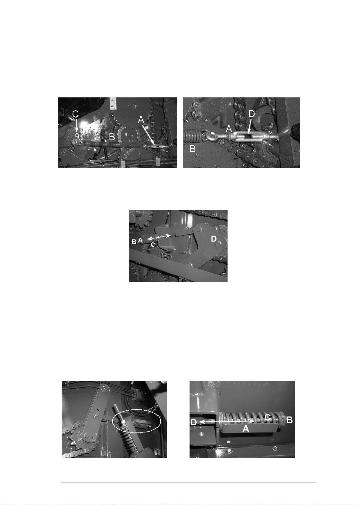
McHale Fusion 3 Baler & Wrapper
10.13.1 Main drive chain adjustment
Adjust turn buckle (A) until the gap (D) is 25 mm. As the chain wears the gap (D) will
need to be reduced. If there is no more adjustment available in the turn buckle (A), the
end of the spring (B) can be moved to location (C) on the chain tensioner bracket.
Figure 10.n - Main drive chain adjustment
10.13.2 Bottom chamber door chain adjustment
Figure 10.o - Bottom chamber door chain adjustment
Adjust M12 nyloc nut and nut (B) until compression of spring (C) has reached the same
length as spring guide (A). Spring guide (A) is an indicator only and always inspect
chain tension after adjustment, as greater spring compression may be required, due to
chain wear, chain damage, etc.
10.13.3 Top chamber door chain adjustment
Adjust as discussed in Section 10.13.2, but at the location as shown.
94
Figure 10.p - Top chamber door chain adjustment
Page 95
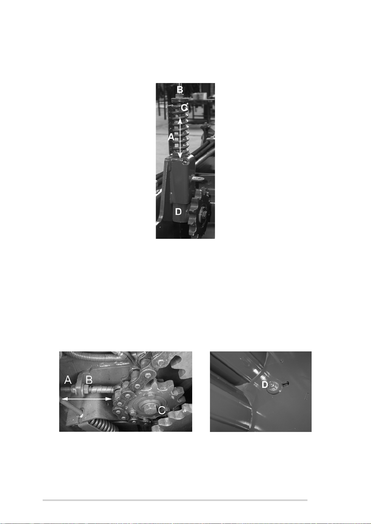
McHale Fusion 3 Baler & Wrapper
10.13.4 Bottom door to main drive chain adjustment
Adjust as discussed in Section 10.13.2, but at the location as shown.
Figure 10.q - Bottom door to main drive chain adjustment
10.13.5 Front chamber segment chain adjustment
Adjustment of the front chamber chain will require the use of a 19 mm and 24 mm
spanners and socket and is carried out as follows:
1. Loosen nyloc nut (D) about 1 turn anti-clockwise and loosen locknut (B) in the
direction shown.
2. Tighten (A) until the chain is taut, do not overtighten!
3. Tighten nyloc nut (D) and bolt (C) when the chain is taut, i.e. minimal sag.
Figure 10.r - Front chamber segment chain adjustment
95
Page 96
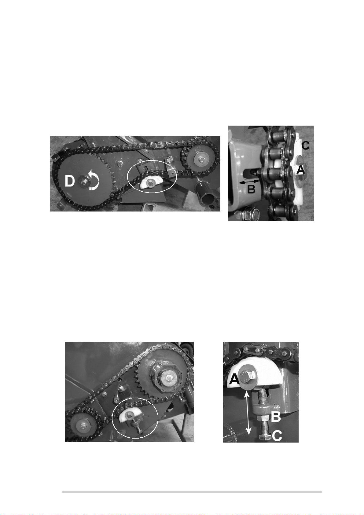
McHale Fusion 3 Baler & Wrapper
10.13.6 Pick-up reel tine chain adjustment
To adjust tine reel chain the use of a 17 mm spanner and socket is required.
1. Loosen (A) and turn tine sprocket (D) anticlockwise, as shown below.
2. Apply upward pressure (along slot B) to nylon chain slide (C), while continuing
to hold sprocket (D) in position.
3. Tighten (A) and ensure that sagging is kept to a minimum.
Figure 10.s - Pick-up reel tine chain adjustment
10.13.7 Reel drive chain adjustment
To adjust the reel drive chain the use of both a 17 mm and 19 mm spanner and socket
are required:
1. Using 17 mm tools, loosen (A) anticlockwise by approx. 1 turn.
2. Using a 19 mm spanner, loosen locknut (B).
3. Tighten setscrew (C) until there is little or no sagging of the chain and retighten
bolt (A).
4. Retighten locknut (B).
96
Figure 10.t - Reel drive chain adjustment
Page 97
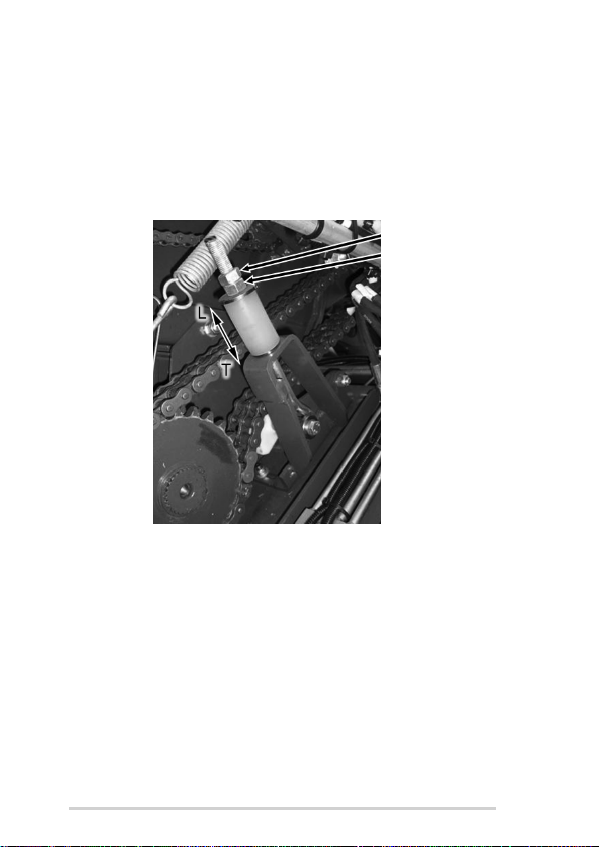
McHale Fusion 3 Baler & Wrapper
Upper Nut
Lower Nut
10.13.8 Chopper unit duplex chain adjustment
To adjust the duplex chain the following tools are required; two 24 mm spanners.
Follow the procedure below:
1. Hold the lower nut and loosen the upper nut.
2. To tighten - screw down the lower nut in the direction T.
3. When the chain is at the required tension, screw down the upper nut.
4. Lock the two nuts together to secure in place.
Figure 10.u - Chopper unit duplex chain adjustment
97
Page 98

McHale Fusion 3 Baler & Wrapper
11
Accessories & Optional Equipment
Certain accessories and optional equipment may or may not be available in all
countries, depending on varying circumstances. The following key symbols help to
explain what is sold as standard and what is optional equipment, or may not be
available on the McHale Fusion 3. They are only correct at the time of print and may
vary.
Key symbols
Standard equipment
Optional equipment
11.1 Drawbar hitch options
Low drawbar hitch
Depending on the country of use this drawbar type is standard, but the high drawbar
hitch is available as an option.
High drawbar hitch
Depending on the country of use this drawbar type is standard, but the low drawbar
hitch is available as an option.
11.2 Stand options
Stand type A
This is a static swing-down stand (fixed) and is suitable for use on the low drawbar hitch
only!
Stand type B
This is a hand operated swing-down stand (adjustable screw and is suitable for raising
or lowering the machine for tractors that have static drawbar hitches. This stand type
is available on the low drawbar hitch only.
Stand type C
This is a hand operated fixed stand (adjustable screw) that comes as standard on the
high drawbar hitch option. This is raised and lowered by means of a crank-handle.
98
Page 99

McHale Fusion 3 Baler & Wrapper
11.3 Brake options
Figure 11.a - Braked Axle
Hydraulic brakes
This system utilises one hose for connection to the tractors hydraulic brake coupling.
This is the most common system on the machine.
Air brakes
This system utilises two air brake couplings and the use of which may be mandatory in
certain countries. Always obey local road regulations!
11.4 Tyre options
Type Details Part No
A
B
C
11.5 Side tip option
Vredestein 560/60 R22.5 (Flo-Pro) CWH00053
BKT 560/60 R22.5 CWH00068
Vredestein 650/50 R22.5 (Flo-Pro) CWH00054
The side tip option is used for knocking the bale onto it’s side and is very useful for
course ground with strong stubble (which may have a tendency to puncture the film),
as it allows the bale to land on it’s edge, which has a much higher degree of film
coverage. It is also very useful on hilly/sloping ground as it can prevent bales from
rolling, when they land on their side.The side tip is attached to the rear wrapping cradle.
99
Page 100

McHale Fusion 3 Baler & Wrapper
11.6 Selectable Knives
This system gives the operator the option of using 0, 11, 12 or 23 knives.
Figure 11.b - Selectable Knive Chopper unit
11.7 Crop Roller
The crop roller aids the crop transfer from the pick-up reel in to the rotor.
100
Figure 11.c - Crop Roller
 Loading...