

Page 1

MP Series
A Division of Systems, LLC
Dock Leveler
Owner’s/User’s Manual
McGuire • Division of Systems, LLC • W194 N11481 McCormick Drive • Germantown, WI 53022
800.624.8473 • fax: 262.255.5917 • www.wbmcguire.com • [email protected]
Printed in U.S.A.
© 2019 Systems, LLC - All Rights Reserved
Manual No. 4111-0019
June 2019
Page 2

Table of Contents
Page
Precautions
Recognize Precautionary Information ................................................ 1
General Operational Precautions ........................................................ 1
Operational Precautions ...................................................................... 2
Safety Decals ......................................................................................... 4
Placard ................................................................................................... 5
Owner’s/User’s Responsibilities ......................................................... 6
Introduction
General Information .............................................................................. 8
Component Identication ..................................................................... 9
Installation
Installation Precautions ...................................................................... 10
Prepare Pit ............................................................................................ 12
Prepare Dock Leveler .......................................................................... 13
Install Dock Leveler ............................................................................. 14
Placard Installation Instructions ........................................................ 20
Operation
Operational Precautions ..................................................................... 21
Operating Instructions ........................................................................ 22
Maintenance
Maintenance Precautions .................................................................... 24
Periodic Maintenance .......................................................................... 25
Adjustments
Adjust Main Spring & Lip Assist Spring Tension ............................. 26
Adjust Lip Stop Bolt ............................................................................ 28
Troubleshooting
Troubleshooting ................................................................................... 30
Parts
Hold-Down Components ..................................................................... 32
Main Lift Springs .................................................................................. 33
Frame Components ............................................................................. 34
Platform Components ......................................................................... 36
Weather Seals....................................................................................... 38
Toe Guards ........................................................................................... 39
Miscellaneous
Customer Information ......................................................................... 41
Warranty ................................................................................ Back Cover
Page 3
e
PRECAUTIONS
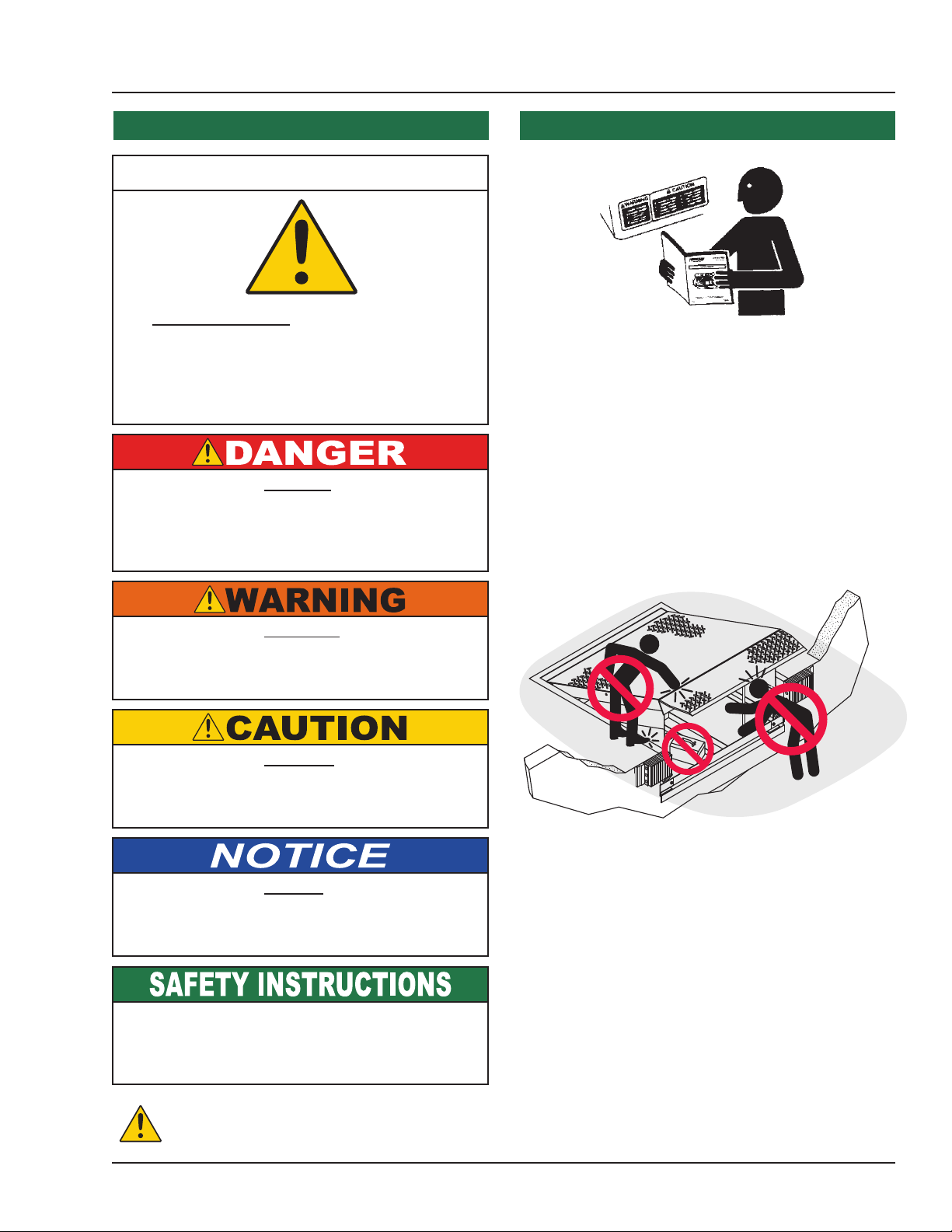
Recognize Precautionary Information
Safety-Alert Symbol
The Safety-Alert Symbol is a graphic representation
intended to convey a safety message without the
use of words. When you see this symbol, be alert
to the possibility of death or serious injury. Follow
the instructions in the safety message panel.
The use of the word DANGER signies the
presence of an extreme hazard or unsafe practice
which will most likely result in death or severe
injury.
General Operational Precautions
Read and understand the Owner’s/User’s Manual and
become thoroughly familiar with the equipment and its
controls before operating the dock leveler.
Never operate a dock leveler while a safety device or
guard is removed or disconnected.
Never remove DANGER, WARNING, or CAUTION
signs, Placards or Decals on the equipment unless
replacing them.
The use of the word WARNING signies the
presence of a serious hazard or unsafe practice
which could result in death or serious injury.
The use of the word CAUTION signies possible
hazard or unsafe practice which could result in
minor or moderate injury.
The use of the word NOTICE indicates information
considered important, but not hazard-related, to
prevent machine or property damage.
Indicates a type of safety sign, or separate panel on
a safety sign, where safety-related instructions or
procedures are described.
n
o
Z
g
n
i
t
a
r
e
p
O
o
Z
g
n
i
t
a
r
e
p
O
Figure 1
Do not start the equipment until all unauthorized
personnel in the area have been warned and have
moved outside the operating zone (see Figure 1).
Remove any tools or foreign objects from the
operating zone before starting.
Keep the operating zone free of obstacles that could
cause a person to trip or fall.
e
n
WARNING: This product can expose you to chemicals including lead, which are known to the State of California to
cause cancer or birth defects or other reproductive harm. For more information go to www.P65Warnings.ca.gov
4111-0019 — June 2019
© 2019 Systems, LLC
1
Page 4
PRECAUTIONS
Operational Precautions
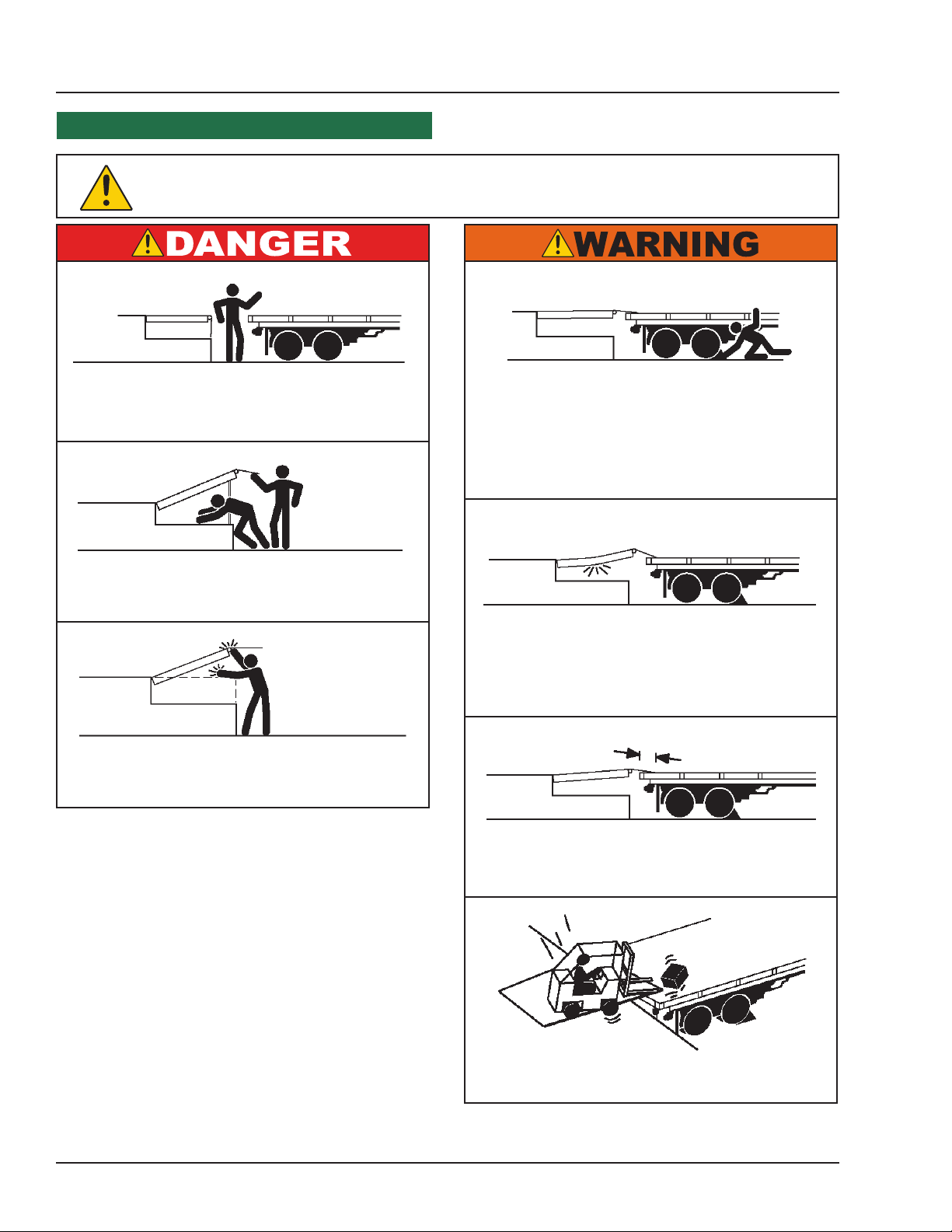
Learn the safe way to operate this equipment. Read and understand the
manufacturer’s instructions. If you have any questions, ask your supervisor.
Stay clear of dock leveling device when transport
vehicle is entering or leaving area.
Do not move or use the dock leveling device if
anyone is under or in front of it.
Keep hands and feet clear of pinch points. Avoid
putting any part of your body near moving parts.
Chock/restrain all transport vehicles. Never
remove the wheel chocks or release the
restraining device until loading or unloading is
nished, and transport driver has been given
permission to drive away.
Do not use a broken or damaged dock leveling
device or restraining device. Make sure proper
service and maintenance procedures have been
performed before using.
Make sure lip overlaps onto transport vehicle bed
at least 4 in. (102 mm).
Keep a safe distance from both side edges.
2
4111-0019 — June 2019
© 2019 Systems, LLC
Page 5
Operational Precautions
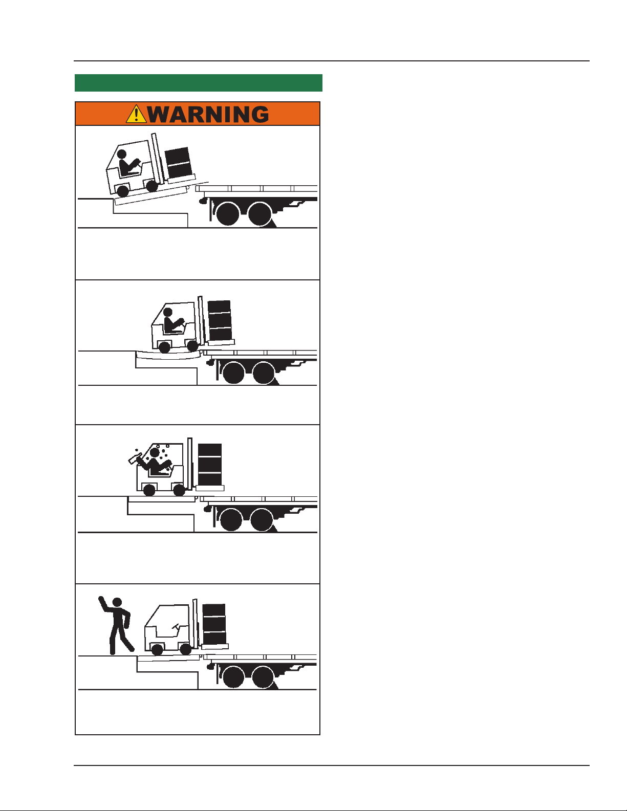
Do not use dock leveling device if transport vehicle
is too high or too low.
PRECAUTIONS
Do not overload the dock leveling device.
Do not operate any equipment while under the
inuence of alcohol or drugs.
Do not leave equipment or material unattended on
dock leveling device.
4111-0019 — June 2019
© 2019 Systems, LLC
3
Page 6
2.43"
FORK
HERE
FORK
HERE
5.05"
5.93"
PRECAUTIONS
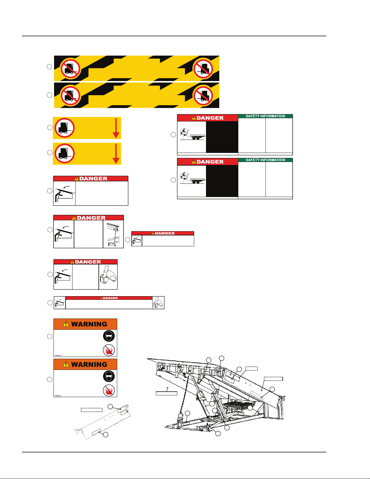
Safety Decals
1
1
3
3
5
6
11
7
FORK THIS SIDE
FORK THIS SIDE
1751-0329
1751-0330 Rev C
1751-0330
Two positions one on top of each fork pocket.
CRUSH HAZARD
DO NOT ENTER P IT unless dock le veler is
secure ly supported by maintenan ce prop. Plac e
barrie rs on driveway and do ck floo r to i ndicate
servic e work being perfo rmed. Failur e to comply
will resul t i n d eath or serious inju ry. R efer to
owner ‘s/user‘s manual for proper maintenanc e
proced ures.
1751-0726
CRUSH HAZARD
Maintenance prop must
support leveler behind bar.
Do not force maintenance
prop forward of bar to
support lip. Refer to
owner’s/user’s manual for
proper use. Failure to
comply will result in
death or serious injury.
1751-0727
CRUSH HAZARD
Open the pin latch and insert
through the maintenance
prop housing and prop
completely. Close the pin latch
to secure prop. Use every
time dock leveler is serviced.
Failure to comply will result
in death or serious injury.
1751-0731
CRUSH HAZARD
Do not work under dock leveler unless this maintenance prop has been secured in the
upright position. Failure to comply will result in death or serious injury. See owner’s/user’s
manual for proper procedures
1751-0729
1751-0330 Rev C
1751-0731 Rev A
DO NOT
DO NOT
1751-0726 Rev B
CRUSH HAZARD
Do not remove main springs until leveler is securely supported by a
suitable lifting device. Main springs contain stored energy. Be sure springs
10
are fully unloaded and ends are loose before removal. Failure to comply
will result in death or serious injury. Refer to owner’s/user’s manual for
1751-0728
proper maintenance procedure.
1751-0729 Rev A
1751-0727 Rev B
1751-0329 Rev A
1751-0329 Rev A
Unsupported dock leveler
ramps can lower unexpectedly.
Before allowing vehicle to leave
4
Failure to follow posted instructions will result in death or serious injury.
4
Failure to follow posted instructions will result in death or serious injury.
the dock always:
••Ensure no equipment,
material or people are on
dock leveler.
Return dock leveler to its
stored position at dock level.
Unsupported dock leveler
ramps can lower unexpectedly.
Before allowing vehicle to leave
the dock always:
••Ensure no equipment,
material or people are on
dock leveler.
Return dock leveler to its
stored position at dock level.
1751-0730
8
1.800.643.5424
1751-0728 Rev B
8
1.800.643.5424
1751-0651
MP SERIES
9
www.DockSystemsInc.com 1.800.643.5424
1751-0643
PROUDLY
MADE
IN
2
USA
SYSTEMS, INC.
GERMANTOWN,WI
MALVERN,AR
1751-0735
OPERATION
1. Read and follow all instructions and
warnings in owner’s/user’s manual.
2. Use of dock leveler restricted to
trained operators
3. Always chock traile r whe els or
enga ge truc k r estr ain t b efor e
operating dock leveler or beginning to
load or unload.
4. Never use hands or equipment to
move ramp or lip
5. Before activating dock leveler:
•
Ensure trailer is backed in against
bumpers.
•
Remove any end loads if required.
•
Check trailer alignment to avoid lip
interference. If lip does not lower to
trailer bed, reposition vehicle.
6. Ensure truck bed supports extended
lip or leveler frame supports the ramp
before driving on ramp.
Call 262.255.1510 for replacement placards, warning labels, or owner’s/user’s manuals.
OPERATION
1. Read and follow all instructions and
warnings in owner’s/user’s manual.
2. Use of dock leveler restricted to
trained operators
3. Always chock traile r whe els or
enga ge truc k r estr ain t b efor e
operating dock leveler or beginning to
load or unload.
4. Never use hands or equipment to
move ramp or lip
5. Before activating dock leveler:
•
Ensure trailer is backed in against
bumpers.
•
Remove any end loads if required.
•
Check trailer alignment to avoid lip
interference. If lip does not lower to
trailer bed, reposition vehicle.
6. Ensure truck bed supports extended
lip or leveler frame supports the ramp
before driving on ramp.
Call 262.255.1510 for replacement placards, warning labels, or owner’s/user’s manuals.
7. Stay clear of hinges and front and
sides of moving dock leveler.
8. N e v e r us e d a m a g e d o r
malfunctioning dock leveler. Report
problems immediately to supervisor.
MAINTENANCE/SERVICE
1. Read and follow all instructions,
wa rn in gs an d ma in te na n ce
schedules in t he own er‘s/user ‘s
manual.
2. Maintenance/Service of dock leveler
restricted to trained personnel.
3. Place barriers on the driveway and
dock floor to indicate service work is
being performed.
4. DO NOT ENTER PIT unless dock
leveler is securely supported by
maintenance prop.
5. If electrically powered turn off and use
OSHA lockout/tagout procedures.
7. Stay clear of hinges and front and
sides of moving dock leveler.
8. N e v e r us e d a m a g e d o r
malfunctioning dock leveler. Report
problems immediately to supervisor.
MAINTENANCE/SERVICE
1. Read and follow all instructions,
wa rn in gs an d ma in te na n ce
schedules in t he own er‘s/user ‘s
manual.
2. Maintenance/Service of dock leveler
restricted to trained personnel.
3. Place barriers on the driveway and
dock floor to indicate service work is
being performed.
4. DO NOT ENTER PIT unless dock
leveler is securely supported by
maintenance prop.
5. If electrically powered turn off and use
OSHA lockout/tagout procedures.
1751-0730 Rev B
1751-0730 Rev B
www. .comDockSystemsInc
www. .comDockSystemsInc
TM
4
Device may contain stored energy.
Decice is not adjustable.
12
Do not attempt to service.
Failure to comply could result in serious
injury or death.
Refer to owner’s/user’s manual for proper
replacement procedures.
Device may contain stored energy.
Decice is not adjustable.
Do not attempt to service.
12
Failure to comply could result in serious
injury or death.
Refer to owner’s/user’s manual for proper
replacement procedures.
1751-0043
Right Platform Side
12
6
Right Platform Side
4
8
9
5
12
10
4
Serial Tag
9
Left Platform Side
1
3
7
1
Figure 2
11
2
Decal Placement
for MP Series
4111-0019 — June 2019
© 2019 Systems, LLC
Page 7
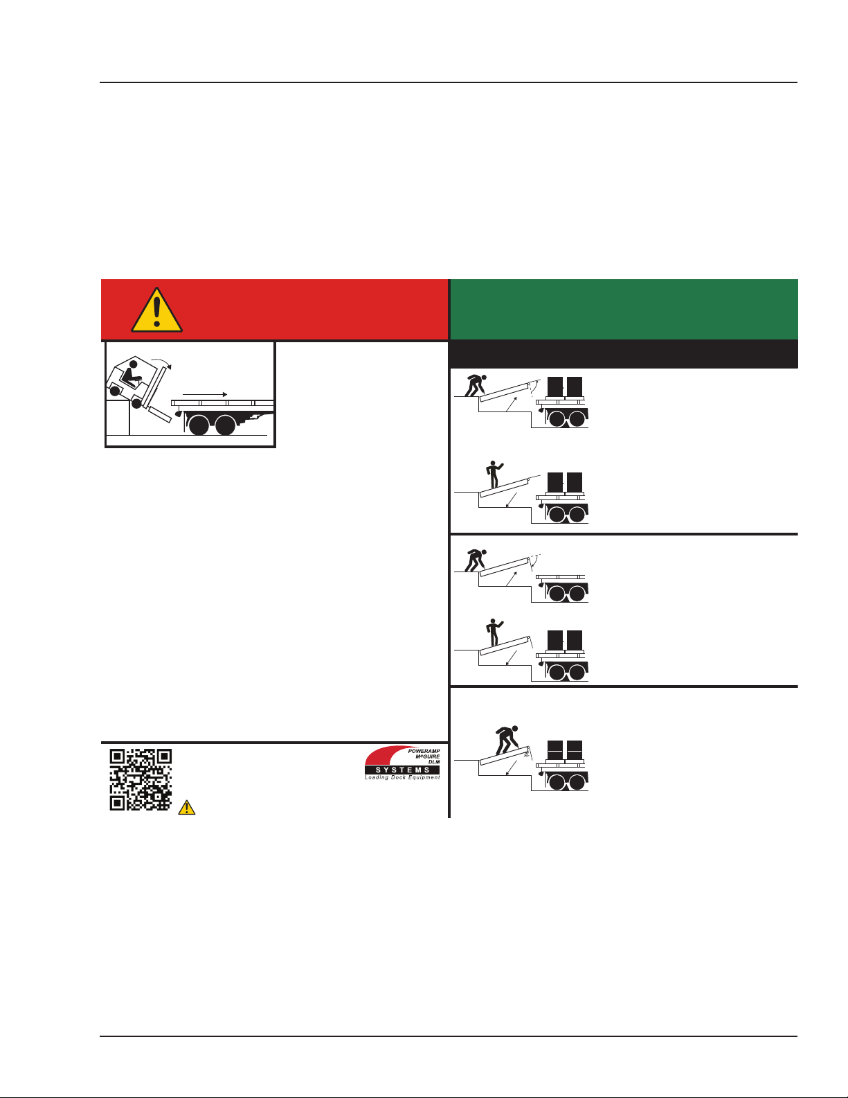
Placard
OPERATING
PRECAUTIONS
DANGER
• Read and follow all
instructions, warnings, and
maintenance schedules in
the manual and on placards.
• Operation and servicing of
dock leveler is restricted to
authorized personnel.
• Always chock transport vehicle wheels or engage vehicle restraint
and set parking brakes before operating dock leveler or beginning
to load or unload.
• Before activating dock leveler, check to make sure the transport
vehicle is positioned squarely against dock bumpers. Ensure lip will
avoid contact with transport vehicle frame, sides and cargo during
dock leveler activation. If contact is likely or observed, reposition
transport vehicle.
• Ensure the transport vehicle oor supports extended lip or the
leveler frame (lip keepers or below dock endload supports) supports
the ramp before driving on ramp.
• Stay clear of hinges and front and sides of moving dock leveler.
• Never use hands or equipment to move the ramp or lip.
• Never use damaged or malfunctioning dock leveler. Report problems
immediately to supervisor.
• Always store dock leveler and remove people, material, and
equipment from ramp before vehicle leaves the dock.
• DO NOT ENTER PIT unless dock leveler is securely supported
and proper lockout/tagout procedures have been completed. See
“Maintenance Precautions” in Owner’s/User’s Manual.
FAILURE TO FOLLOW THESE INSTRUCTIONS WILL RESULT
IN DEATH OR OTHER SERIOUS INJURY.
Scan to view our owner’s/user’s manuals online.
www.LoadingDockSystems.com
1.800.643.5424
Call for additional placards, or manuals, or with questions
regarding proper use, maintenance, and repair of dock leveler.
1751-0875
WARNING: CANCER AND REPRODUCTIVE HARM
www.P65Warnings.ca.gov
1751-0875 Rev D
INSTRUCTIONS
MECHANICAL DOCK LEVELERS
NORMAL OPERATION
1. Raise the platform by pulling and holding
the platform release ring.
2. Hold the platform release ring until the lip
is fully extended, then release the platform
release ring. Walk out onto the platform.
The platform will lower until lip is resting
on the transport vehicle.
STORING LEVELER
1. Pull the platform release ring. Slowly walk
the platform down allowing enough time
for the lip to fold, clearing the transport
vehicle. Once lip clears transport vehicle,
continue to walk leveler to the cross-trafc
position.
BELOW DOCK ENDLOADING
• Pull and hold the platform release ring until
the platform is at the fully-raised position.
Slowly walk the platform down allowing
enough time for the lip to fold. Just before
the platform reaches the cross-trafc
position, pull and hold the safety leg
retract pull ring located in a recess at front
of the platform. The platform will continue
lowering to the full below dock position.
4111-0019 — June 2019
© 2019 Systems, LLC
5
Page 8

OWNER’S/USER’S RESPONSIBILITIES
1) The manufacturer shall provide to the initial
purchaser and make the following information
readily available to the owners/users and their
agents, all necessary information regarding
Safety Information, Operation, Installation and
Safety Precautions, Recommended Initial and
Periodic Inspections Procedures, Planned
Maintenance Schedule, Product Specications,
Troubleshooting Guide, Parts Break Down,
Warranty Information, and Manufacturers
Contact Information, as well as tables to identify
the grade(slope) for all variations of length or
conguration of the dock leveling device and
information identifying the maximum uncontrolled
drop encountered when sudden removal of
support while in the working range of the
equipment.
2) When selecting loading dock safety equipment,
it is important to consider not only present
requirements but also future plans and any
possible adverse conditions, environmental
factors or usage. The owners/users shall provide
application information to the manufacturer
to receive recommendations on appropriate
equipment specications and capacity.
3) The owner/user must see all nameplates,
placards, decals, instructions and posted
warnings are in place and legible and shall not
be obscured from the view of the operator or
maintenance personnel for whom such warnings
are intended for. Contact manufacturer for any
replacements.
4) Dock leveling devices may become hazardous
if the manufacturer’s instructions regarding
modications or adjustments are not followed.
Modications or alterations of dock leveling
devices shall only be made with prior written
approval from the original manufacturer. These
changes shall be in conformance with all
applicable provisions of the MH30.1 standard
and shall also satisfy all safety recommendations
of the original equipment manufacturer of the
particular application.
5) The owner/user should recognize the inherent
dangers of the interface between the loading
dock and the transport vehicle. The owner/ user
should, therefore, train and instruct all operators
in the safe operation and use of the loading dock
equipment in accordance with manufacturer’s
recommendations and industry standards.
Eective operator training should also focus on
the owner’s/user’s company policies, operating
conditions and the manufacturer’s specic
instructions provided with the dock leveling
device. Maintaining, updating and retraining all
operators on safe working habits and operation of
the equipment, regardless of previous experience,
should be done on a regular basis and should
include an understanding and familiarity with all
functions of the equipment. Owners/users shall
actively maintain, update and retrain all operators
on safe working habits and operations of the
equipment.
6) An operator training program should consist of,
but not necessarily be limited to, the following:
a) Select the operator carefully. Consider the
physical qualications, job attitude and aptitude.
b) Assure that the operator reads and fully
understands the complete manufacturer’s owners/
users manual.
c) Emphasize the impact of proper operation
upon the operator, other personnel, material
being handled, and equipment. Cite all rules and
why they are formulated.
d) Describe the basic fundamentals of the dock
leveling device and components design as related
to safety, e.g., mechanical limitation, stability,
functionality, etc.
e) Introduce the equipment. Show the control
locations and demonstrate its functions.
Explain how they work when used properly and
maintained as well as problems when they are
used improperly.
f) Assure that the operator understands the
capacity rating, nameplate data, placards and all
precautionary information appearing on the dock
leveling device.
g) Supervise operator practice of equipment.
h) Develop and administer written and practical
performance tests. Evaluate progress during and
at completion of the course.
i) Administer periodic refresher courses. These
may be condensed versions of the primary course
and include on-the-job operator evaluation.
6
4111-0019 — June 2019
© 2019 Systems, LLC
Page 9

OWNER’S/USER’S RESPONSIBILITIES
7) Loading dock safety equipment should never
be used outside of its vertical working range, or
outside the manufacturer’s rated capacity. It shall
also be compatible with the loading equipment
and other conditions related to dock activity.
Please consult the manufacturer if you have any
questions as to the use, vertical working range or
capacity of the equipment. Only properly trained
and authorized personnel should operate the
equipment.
8) It is recommended that the transport vehicle
is positioned as close as practical to the dock
leveling device and in contact with both bumpers.
When an industrial vehicle is driven on or o a
transport vehicle during loading and unloading
operations, the transport vehicle parking brakes
shall be applied and wheel chocks or a restraining
device that provides equal or better protection of
wheel chocks shall be engaged. Also, whenever
possible, air-ride suspension systems should have
the air exhausted prior to performing said loading
and unloading operations.
9) When goods are transferred between the loading
dock and a trailer resting on its support legs/
landing gear instead of a tractor fth wheel
or converter dolly, it is recommended that an
adequate stabilizing device or devices shall be
utilized at the front of the trailer.
instructions, labels, decals and placards or
their equivalent. Written documentation of
maintenance, replacement parts or damage
should be kept. In the event of damage,
notication to the manufacturer is required.
12) Loading dock devices that are structurally
damaged or have experienced a sudden loss of
support while under load, such as might occur
when a transport vehicle is pulled out from under
the dock leveling device, shall be removed from
service, inspected by a manufacturer’s authorized
representative, and repaired or replaced as
needed or recommended by the manufacturer
before being placed back in service.
10) In order to be entitled to the benets of the
standard product warranty, the dock safety
equipment must have been properly installed,
maintained and operated in accordance with
all manufacturer’s recommendations and/
or specied design parameters and not
otherwise have been subject to abuse, misuse,
misapplication, acts of nature, overloading,
unauthorized repair or modication, application in
a corrosive environment or lack of maintenance.
Periodic lubrication, adjustment and inspection
in accordance with all manufacturers’
recommendations are the sole responsibility of the
owner/user.
11) Manufacturer’s recommended maintenance and
inspection of all dock leveling devices shall be
performed in conformance with the following
practices: A planned maintenance schedule
program must be followed, only trained and
authorized personnel shall be permitted to
maintain, repair, adjust and inspect dock leveling
devices, and only the use of original equipment
manufacturer parts, manuals, maintenance
4111-0019 — June 2019
© 2019 Systems, LLC
7
Page 10
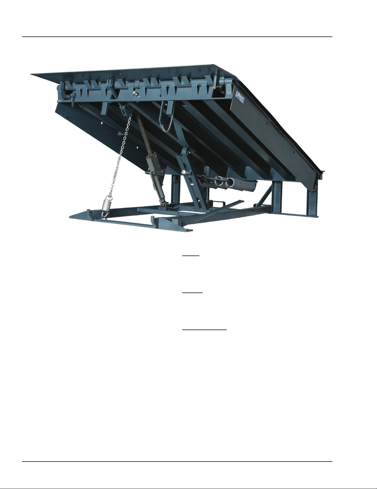
INTRODUCTION
General Information
Figure 3
This manual provides current information on the
MP-series dock leveler. Due to ongoing product
improvement, some parts may have changed, along
with operation and troubleshooting methods. This
manual describes these changes where applicable.
The MP-series mechanical dock leveler design allows
nger tip release pull chain activation with smooth
reliable operation via a cam and roller counterbalance
to assure smooth dependable walk down to trailer bed
with below dock capability included.
The hold down design oats with air ride trailers and
the full width rear compression hinge is designed for
superior strength.
Each MP-series dock leveler has been factory tested
to ensure satisfactory operation.
MP dock levelers are available in the following sizes,
weight capacities, and options:
Width
6 ft (1829 mm)
6-1/2 ft (1981 mm)
7 ft (2134 mm)
Length
6 ft (1829 mm)
8 ft (2438 mm)
10 ft (3048 mm)
Capacity (CIR*)
25,000 lb (11 340 kg)
30,000 lb (13 608 kg)
35,000 lb (15 876 kg)
40,000 lb (18 144 kg)
45,000 lb (20 412 kg)
55,000 lb (22 680 kg)
* CIR (Comparative Industry Rating)
Call McGuire to discuss available options to meet your
specic needs.
Technical Service at 800-643-5424 or [email protected]
8
4111-0019 — June 2019
© 2019 Systems, LLC
Page 11
INTRODUCTION
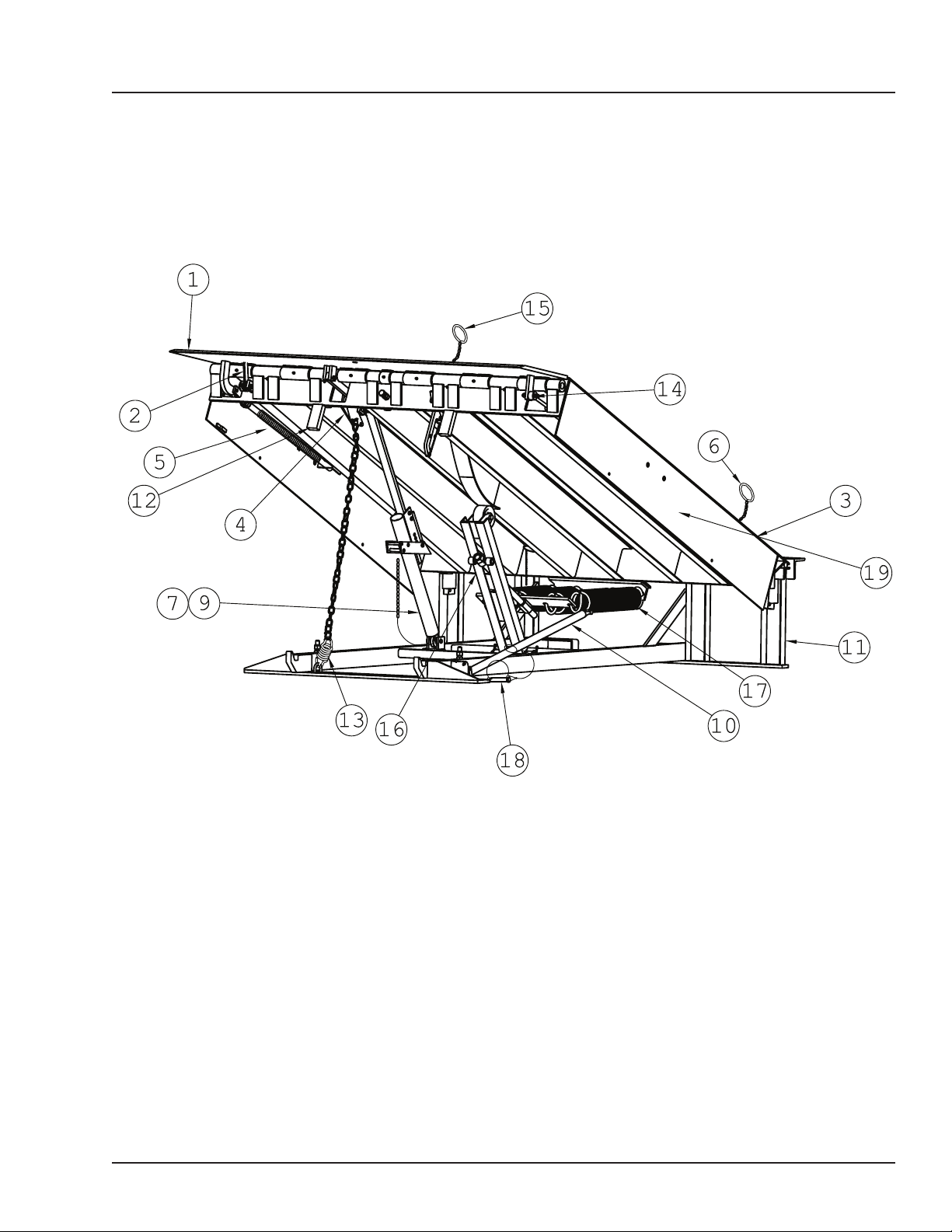
Component Identication
Inspect package and all components. Report any missing or damaged items immediately
and note on the shipping Bill Of Lading (BOL).
1 — Lip
2 — Lip Maintenance Prop
3 — Platform
4 — Bell Crank
5 — Lip Assist Spring
4111-0019 — June 2019
© 2019 Systems, LLC
Figure 4
6 — Hold Down Release Ring
7 — Ratchet Pawl & Bar
9 — Hold Down
10 — Platform Maintenance Prop
11 — Main Base Frame
12 — Safety Leg Assy.
13 — Lip (Snubber) Spring
14 — Lip Shock Absorber
15 — Safety Leg Pull Chain
16 — Lift Arm Assembly
17 — Lift (Main) Spring
18 — Prop. Pin and Clip
19 — Working Range Toe Guards
9
Page 12
INSTALLATION
Installation Precautions
It is recommended and good safety practice to use
an additional means to support the dock platform
and lip anytime when physically working in front of
or under the dock leveler. This additional means
may include, but is not limited to a boom truck, fork
truck, stabilizing bar or equivalent.
Post safety warnings and barricade the work
area at dock level and ground level to prevent
unauthorized use of the dock leveler before
installation has been completed.
DO NOT grind or weld if hydraulic fluid or other
flammable liquid is present on the surface to be
ground or welded.
DO NOT grind or weld if uncontained hydraulic fluid
or other flammable liquid is present. Stray sparks
can ignite spills or leaks near the work area. Always
clean up the oil leaks and spills before proceeding
with grinding or welding.
Always keep a fire extinguisher of the proper type
nearby when grinding or welding.
A hard hat or other applicable head protection
should always be worn when working under or
around a dock leveler.
Always stand clear of platform lip when working in
front of the dock leveler.
Only trained installation professionals with the
proper equipment should install this product.
10
4111-0019 — June 2019
© 2019 Systems, LLC
Page 13
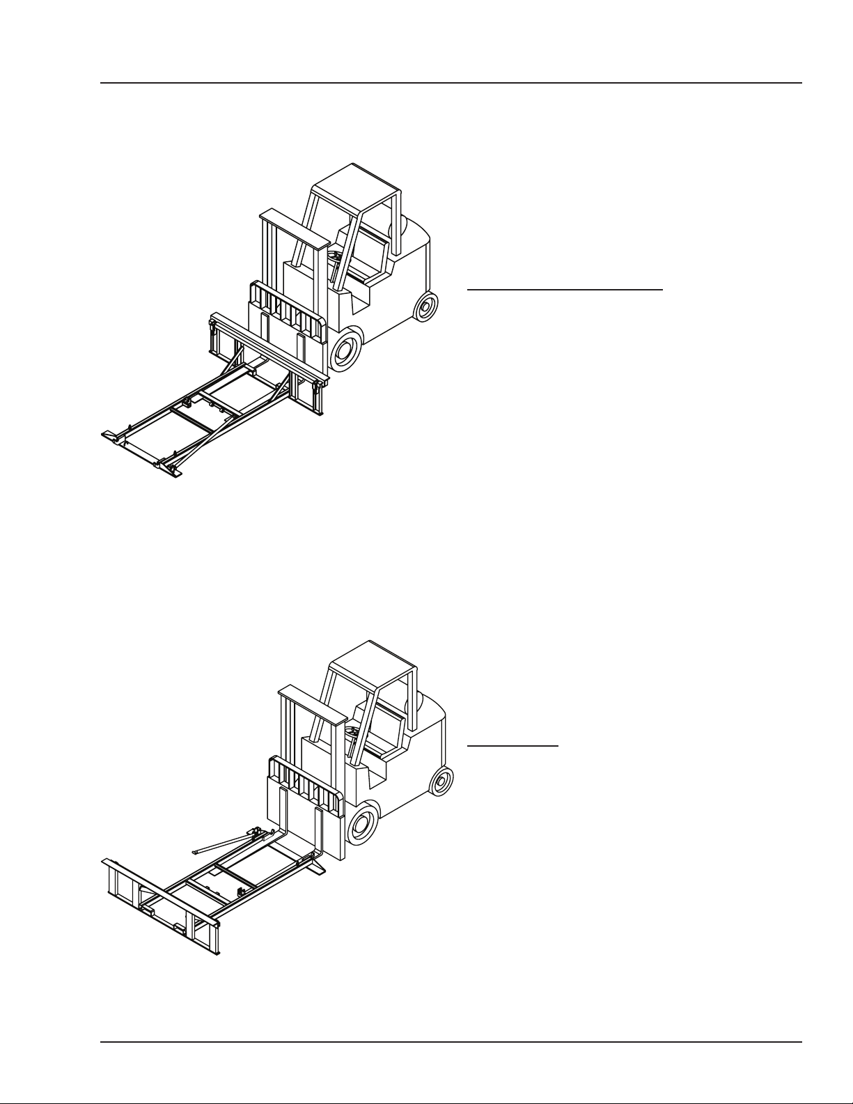
Leveler Forklift Pick-Up*
INSTALLATION
Rear Pick-Up (recommended)
To pick up the dock leveler from the rear, slide forks
into the fork slots and under the cross member as
shown in Figure 5.
Figure 5
Front Pick-Up
To pick up the dock leveler from the front, move forks
closer together and slide over the frame and under
the crossmember as shown in Figure 6. It may be
necessary to remove the shipping bands from the
unit to gain access to the front, by lifting the lip up
then sliding the forks under the cross member.
Figure 6
*
Dock leveler platform not shown for clarity.
4111-0019 — June 2019
© 2019 Systems, LLC
11
Page 14
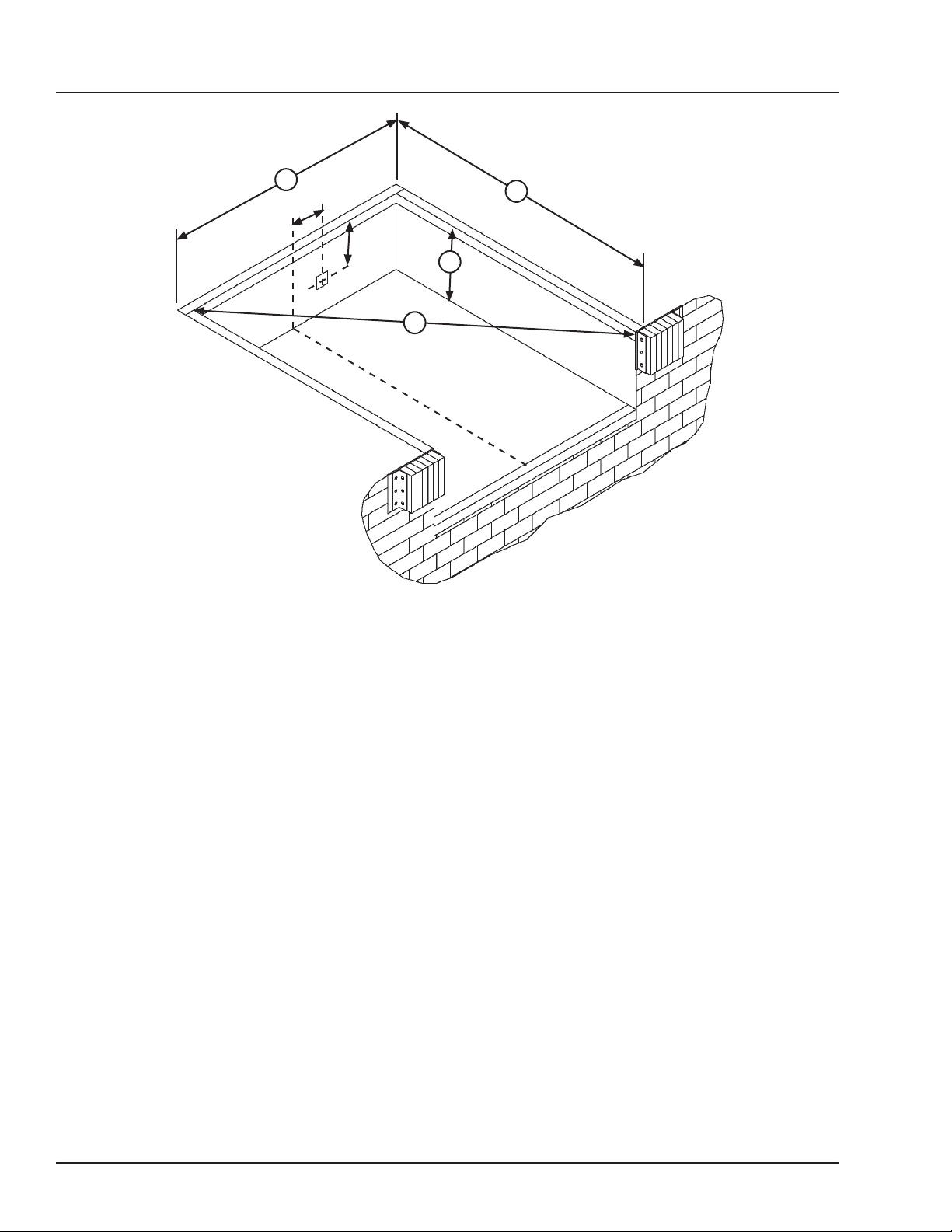
INSTALLATION
Prepare Pit
A
10”
14”
A—Pit Width
(Front and Rear)
C
L
B— Dock Floor-to-Pit Floor
(All Four Corners)
Before lowering the dock leveler into the pit, the
following must be performed:
B
D
C
L
Figure 7
C— Pit Length
(Both Sides of Pit)
C
D— Pit Corner-to-Corner
(Top, Bottom, and Both Sides)
1. Remove all debris from the pit and sweep the pit
clean.
2. Check the entire dock leveler pit for proper
construction according to approved/certied pit
drawings. Make sure pit is square by making the
following measurements (see Figure 7):
• Measure pit width distance (A) at both front and
rear of pit.
• Measure dock floor-to-pit floor distance (B) at all
four corners.
• Measure pit length distance (C) at both sides.
• Measure corner-to-corner (diagonal) distance (D)
at both sides. Take measurements at dock oor
level and at pit oor level.
If any measurement is o by more than 1/8 in. (3.2
mm), contact Systems, LLC Technical Services
before proceeding.
Note: If a junction box is required for electrical
components (such as interlock switches), locate it 10”
o center and 14” down from the curb as shown.
12
4111-0019 — June 2019
© 2019 Systems, LLC
Page 15
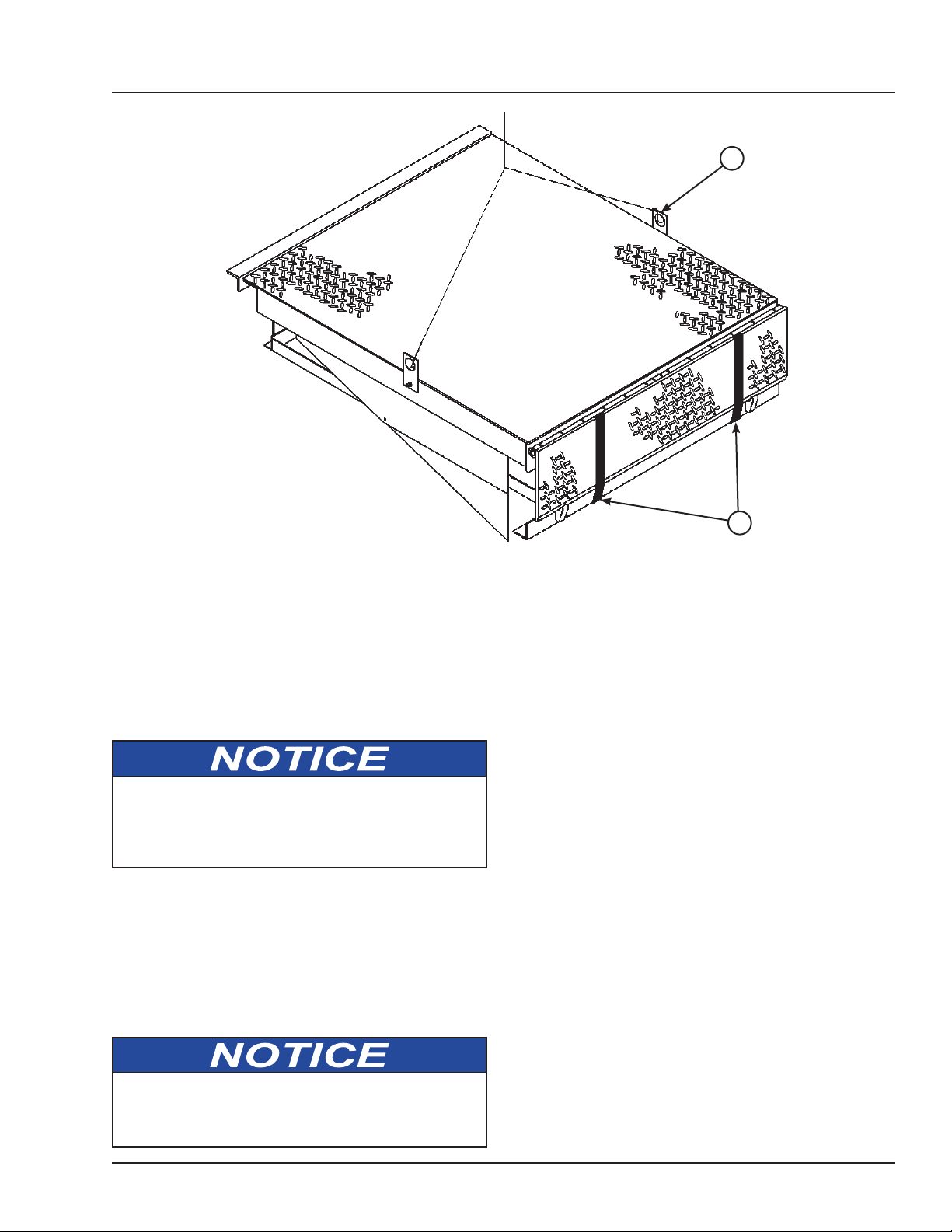
Prepare Dock Leveler
INSTALLATION
A
B
A— Lifting Bracket (2 used) B — Shipping Bands
McGuire dock levelers are shipped with lifting
brackets (A) fastened to the platform side joists,
and shipping bands (B) around the platform lip and
leveler frame (see Figure 8).
1. Remove any bumpers and/or control panels that
may be banded to the frame of the dock leveler.
DO NOT remove the shipping bands (B) around
the platform lip and leveler frame at this time. The
shipping bands are needed to hold the leveler
together during the installation process.
Note: Overall width of platform and lifting brackets
(A) must be kept to a minimum to prevent
interference between the lifting brackets and the pit
walls as the dock leveler is lowered into the pit.
2. Make sure the mounting hardware of lifting
brackets (A) is snug. The brackets should pivot
without binding on the mounting cap screw.
Figure 8
3. Attach lifting chains to lifting brackets (A) and to
a lifting device (i.e., hoist or fork truck) having the
appropriate lifting capacity and reach.
4. Remove wood blocks that are attached to the
leveler frame before putting the dock leveler into the
pit.
5. Proceed to “Install Dock Leveler” on Page 14.
DO NOT over-tighten the lifting bracket hardware.
Over-tightening can damage the weather seal, if
equipped.
4111-0019 — June 2019
© 2019 Systems, LLC
13
Page 16
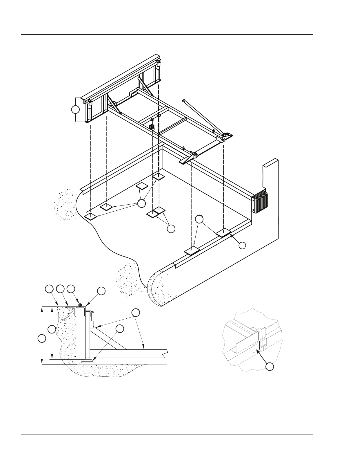
INSTALLATION
A
TOLERANCES
(UNLESS OTHERWISE NOTED)
DRAWN BY
CHECKED BY
DRAWING NO.
DATE
BDK 7/18/2018
S Y S T E M S
L o a d i n g D o c k E q u i p m e n t
P O W E R A M P
M C G U I R E
D L M
MATERIAL
STOCK NO.
GOOD
BAD
Install Dock Leveler
A
F G
E
D E F
L
J
K
H
A— Distance (Leveler Frame
Height)
B— Shim Locations (Under
Rear Vertical Supports)
C— Shim Location (Under
Maintenance Prop)
14
G
H
L
N
K
M
Figure 10
D— Shim Locations (Under
Lip Keepers)
E— Dock Floor
F— Rear Pit Curb Angle
G— String
B
D
J
Figure 9
H— Rear Hinge Frame Angle
J— Shims Location (Under
Lift Arm)
K— Distance (Dock Floor-to-
Pit Floor)
C
P
Figure 11
L— Distance (Top of Shim
M— Shim Stack
N— Dock Leveler Frame
P— Lip Keeper Shim (as
Stack-to-Dock Floor)
required)
4111-0019 — June 2019
© 2019 Systems, LLC
Page 17
INSTALLATION
Install Dock Leveler (continued)
Note: McGuire dock levelers are designed with a
nominal 1/2” (12.7 mm) shimming distance to allow
for pit inconsistencies.
1. Determine height of shim stack (M) for each shim
location (B) by performing the following:
a. Measure leveler frame height distance (A).
b. Measure dock oor-to-pit oor distance
(K) at each shim location (B). Write down the
dimensions obtained at each location.
c. Subtract distance (A) from distance (K) to
obtain the shim height. Repeat for each shim
location.
2. Using the results obtained in step 1, create the
individual shim stacks on the pit oor at location (B).
Build each shim stack (M) with the top shim having
a minimum size of 4-1/2” x 4-1/2” (114.3 mm x 114.3
mm) and each successive lower shim being larger so
the shims can be welded together using a llet weld.
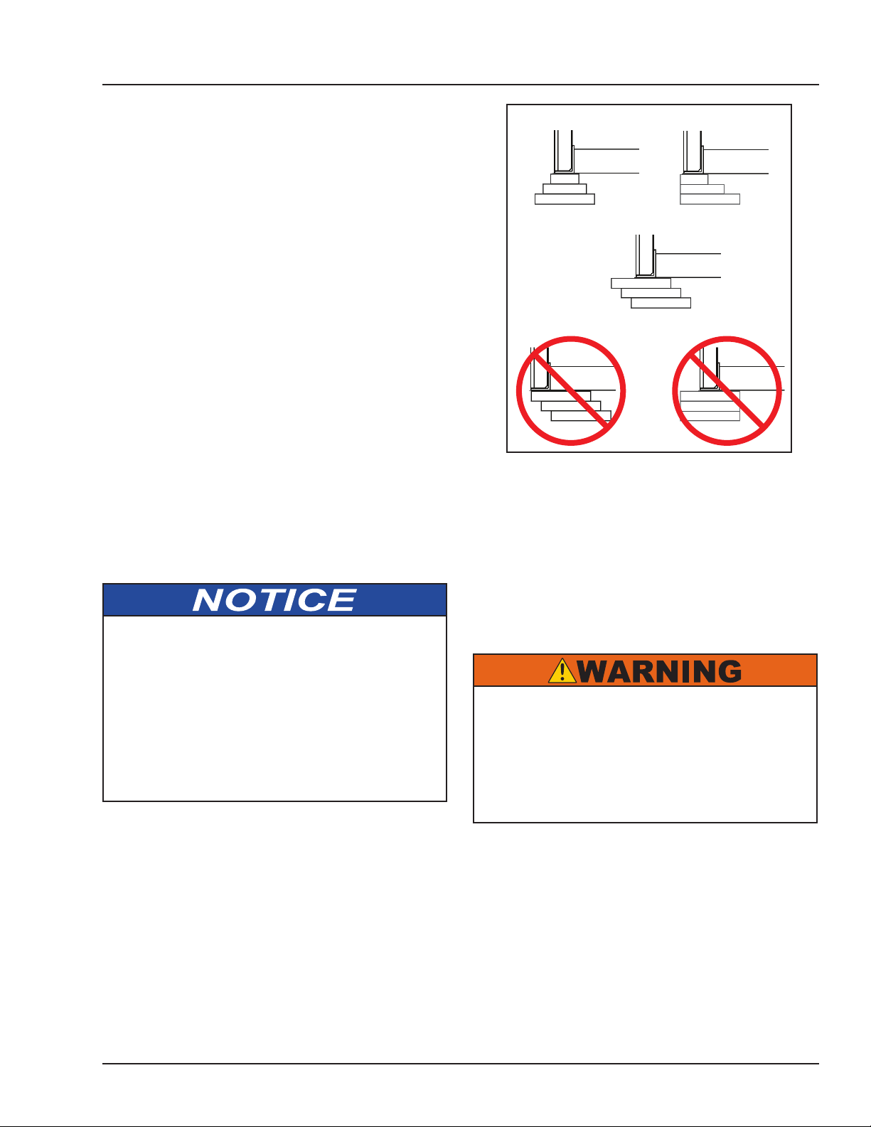
If using oset method, make sure load is over center
of shim stack, NOT over the edge. DO NOT use
straight method. See Figure 12.
The minimum size of the shim that contacts the
leveler frame (i.e. the top shim of each shim stack)
must be at least 4-1/2” x 4-1/2” (114.3 mm x 114.3
mm) to support the full width of the frame rail and to
provide a shelf for a llet weld.
Use the thickest shim stock possible for stability
and weld penetration purposes. DO NOT use
multiple layers of 1/8 in. (3.2 mm) or thinner shim
stock.
Shim Stacking Methods
Pyramid
(Preferred)
Oset w/Load Over Center
(Acceptable)
Oset w/Load Over Edge
(Not Acceptable)
Stepped
(Acceptable)
Straight
(Not Acceptable)
Figure 12
Note: A 1/4” (6.4 mm) thick shim at locations (C and
D) are used only as a starting point. The nal shim
stack height will be determined after dock leveler is
lowered into the pit.
5. Using an appropriate lifting device connected to
the lifting brackets, lower dock leveler into the pit so
rear hinge frame angle (H) is tight against rear pit
curb angle (F) across full width of the leveler frame.
The dock leveler is heavy. Use a lifting device and
chains with the appropriate lifting capacity and
reach.
Always use the lifting brackets provided with the
unit whenever lowering or lifting a dock leveler into
or out of a pit.
Note: To assist in obtaining an accurate
measurement of distance (L), use a string (G) pulled
tight across the pit opening, directly over the shim
locations.
3. Verify that each shim stack is at the correct height
by measuring distance (L) [top of shim stack (M) to
dock oor]. Distance (L) must equal the dock leveler
height (A).
4. Put a 1/4 in. (6.4 mm) thick shim at locations (C
and D).
4111-0019 — June 2019
© 2019 Systems, LLC
6. Allow rear of dock leveler to rest on the rear shims
while keeping the front of the dock leveler level with
the dock oor.
7. Add shims at front shim locations (C and D) so
front of dock leveler will stay level with dock oor
when leveler is resting fully on shims.
15
Page 18
INSTALLATION
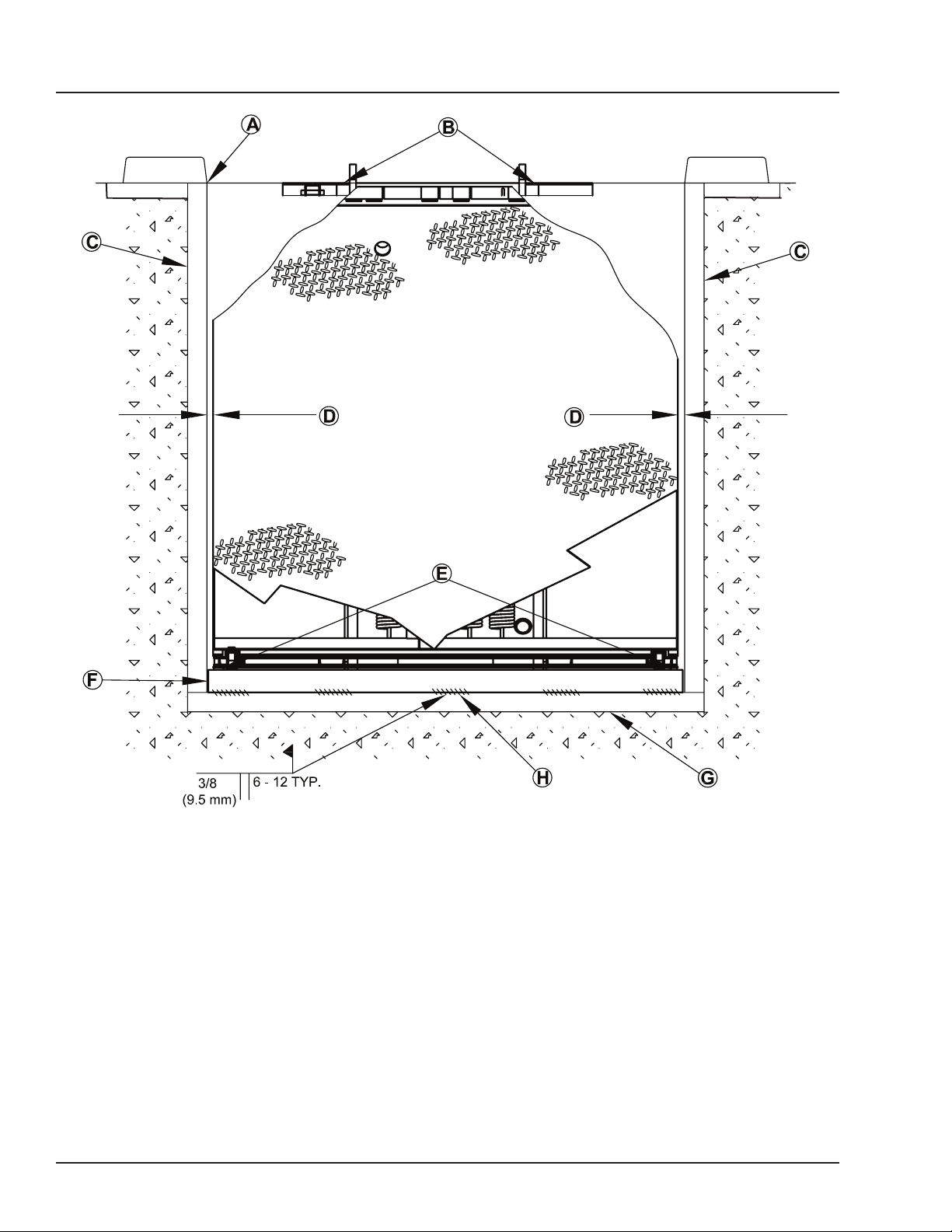
A— Front of Dock Pit
B— Dock Leveler Frame
C— Side Pit Curb Angle
D— Gap [3/4 in. (19 mm)
Minimum]
8. With rear hinge frame angle (F) tight against rear
pit curb angle (G), perform/check the following:
• Pry between the platform and rear hinge frame
angle at locations (E) to make sure rear edge of
platform is parallel to the rear hinge frame angle
(F).
• Gap (D) must exist equally along both sides of
leveler so weather seal (if equipped) will not bind
during dock leveler operation.
16
Figure 13
E— Pry Locations
F— Rear Hinge Frame
Angle
9. If gap (D) cannot be obtained equally at both
sides of leveler, grind or add material at the rear
edge of rear hinge frame angle (F) as needed.
10. Allow the dock leveler to rest fully on the shim
stacks. Check that a smooth and level transition
exists between the dock oor and the dock leveler
platform. Add or remove shims as necessary until a
smooth transition is obtained.
11. If leveler cannot be squared and/or made level
as instructed in steps 8-10, contact Systems, LLC
Technical Services.
G— Rear Pit Curb Angle
H— Flare Bevel Weld, Typical
(To Fit Spacing)
4111-0019 — June 2019
© 2019 Systems, LLC
Page 19

Install Dock Leveler (continued)
DO NOT weld continuously along the full length
of the rear hinge frame angle. This can put
unnecessary stress on the leveler components,
causing the leveler to malfunction and shorten the
lifespan of the aected components.
INSTALLATION
12. With the rear hinge frame angle (F) tight against
the rear pit curb angle (G), weld the rear hinge frame
angle (F) to the rear pit curb angle (G) using a 3/8 in.
(9.5 mm) are bevel skip weld — each weld being 6
in. (152 mm) long.
• Start at each end with a 6 in. (152 mm) long
weld. Space all the other welds out evenly,
leaving approximately 6 in. (152 mm) space
between each weld.
Note: Figure 13 shows a typical weld pattern. The
weld pattern will vary slightly depending on size of
dock leveler.
13. Prior to welding front of frame to curb steel,
remove the shipping bands from around lip and
leveler frame. Operate leveler through full cycle 4-6
times and walk the platform into stored position.
14. Allow platform and lip to oat out of lip keepers,
and shim under front of frame as required to level top
of platform with dock oor.
15. Weld front of dock leveler frame (B) to shims
located under the keepers, then weld the shims to
the front pit curb steel.
16. Disconnect lifting device and chains from the
lifting brackets.
17. Pull and hold the release ring (located in recess
at rear of platform) until the platform is fully raised.
Check for binding as platform rises.
18. Slowly walk out onto the platform to lower the
platform. Allow the platform to lower to the crosstraffic position. Check for binding as platform lowers.
19. If binding occurs, reposition leveler and/or
add or remove shims as necessary. Raise and
lower platform again. If platform still binds, contact
Technical Services for further instructions.
20. Check that the leveler is flush with the dock floor
and that the platform lip contacts both lip keepers
evenly.
4111-0019 — June 2019
© 2019 Systems, LLC
17
Page 20
INSTALLATION
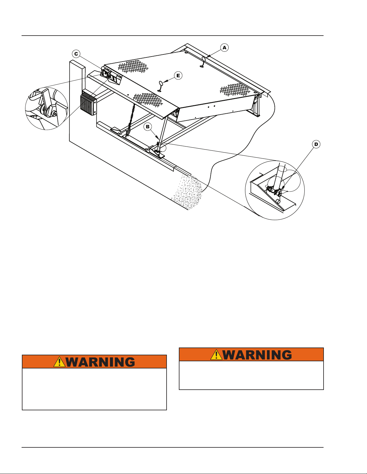
Figure 14
A— Hold-Down Release Ring
B— Maintenance Prop
C— Lip Maintenance Prop
D— Prop Pin and Clip
21. Pull the release ring (A) to raise the platform.
Engage lip maintenance prop (C).
22. Shim and weld the maintenance prop (Figure 14):
a. Install shims under maintenance prop (B)
where prop attaches to leveler frame. Make sure
prop is solidly shimmed.
b. Raise maintenance prop (B) to the service
(upright) position and lock prop in this position
using an OSHA approved locking device.
c. Proceed to step 23.
DO NOT use the maintenance prop to support the
raised platform until the maintenance prop has
been properly shimmed and welded. The shims
must be welded to each other, and also to the
leveler frame.
E— Safety Leg Chain
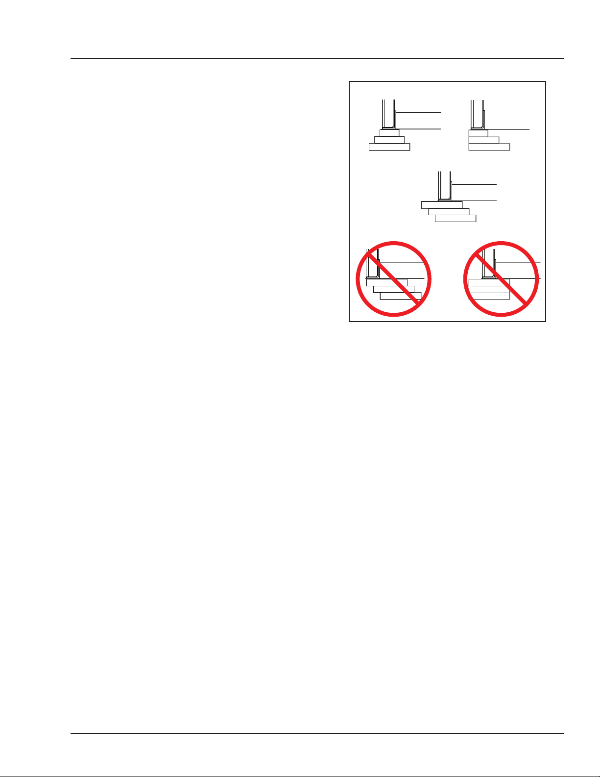
23. Install shims under lift arm (J, Figure 9 on page
14) at locations using an acceptable shimming
method (see Figure 15). The lift arm pivot must be
solidly shimmed the entire length of the lift arm pivot.
Make sure the lift arm pivot is level from side-to-side.
24. Finish weld all shims using a llet weld:
• Weld all shims within each shim stack to each
other, then weld the shim stack to the leveler frame.
• Weld the front leveler frame shim stacks to the
front pit curb steel.
Make sure the platform is properly supported in the
raised position before entering the pit to finish weld
the shims.
25. Remove the lifting brackets from the platform
side joists.
26. Disengage the platform maintenance prop.
18
4111-0019 — June 2019
© 2019 Systems, LLC
Page 21
Install Dock Leveler (continued)
27. Slowly walk out onto the platform to lower the
platform until it is at the cross-traffic (stored) position.
28. Check operation of dock leveler by cycling the
leveler at least four times:
• When the platform is at full height, lip will be fully
extended.
• Lip will begin to drop after the unit begins to
lower to truck bed.
29. Check below-dock position by walking platform
down before lip folds completely:
• Lip will be over lip keepers.
INSTALLATION
Shim Stacking Methods
Pyramid
(Preferred)
Oset w/Load Over Center
(Acceptable)
Stepped
(Acceptable)
• Platform safety legs will be resting on frame.
30. Check full below-dock position by walking the
platform down. Pull and hold safety leg chain (E)
before lip folds completely.
Note: If the lip does not extend fully or lip folds
too quickly, see appropriate symptom in the
Troubleshooting section.
31. When all welding has been completed, paint all
the welds and shims.
32. Install the dock bumpers as required.
33. Install placard (see page 20).
Oset w/Load Over Edge
(Not Acceptable)
Figure 15
Straight
(Not Acceptable)
4111-0019 — June 2019
© 2019 Systems, LLC
19
Page 22
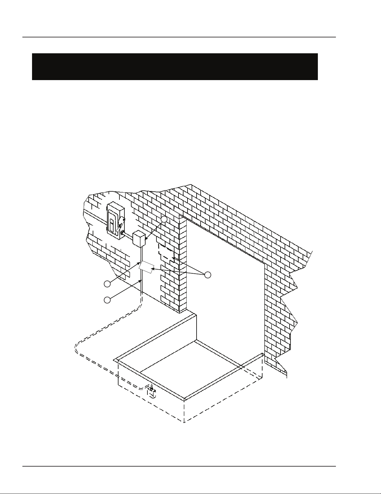
Placard Installation Instructions
Owner/Users are responsible for the installation and placement of product
Make sure placard is in plain view of dock leveler and/or vehicle restraint
Suggested placement of placard is near control box attached to electrical
conduit by using nylon tie. If there is no control box present, mount placard
INSTALLATION
Placard Installation Instructions
• Owner/Users are responsible for the installation and placement of product
placards.
placards.
• Make sure placard is in plain view of dock leveler and/or vehicle restraint
operations.
operations.
• Suggested placement of placard is near control box attached to electrical
conduit by using nylon cable tie. If there is no control box present, mount placard
on wall to the immediate left of leveler at eye level.
on wall to the immediate left of leveler at eye level.
Control Box
A
(Placard placement shown
B
Placard
as example only.)
Nylon Tie
Conduit
C
D
(Placard placement
shown as reference
only.)
A - Control Box B - Placard C - Nylon Cable Tie D - Conduit
Figure 16
20
4111-0019 — June 2019
© 2019 Systems, LLC
Page 23
Operational Precautions
OPERATION
Stay clear of dock leveler and vehicle restraint
when transport vehicle is entering or leaving dock
area.
DO NOT move or use the dock leveler or restraint if
anyone is under or in front of leveler.
Keep hands and feet clear of pinch points. Avoid
putting any part of your body near moving parts.
Only trained personnel should operate the dock
leveler.
DO NOT use a broken or damaged dock leveler.
Make sure proper service and maintenance
procedures have been performed on leveler before
using.
Transport vehicle wheels must be chocked unless
a vehicle restraint is used. Never remove the wheel
chocks until loading/unloading is nished and
transport driver has been given permission to leave.
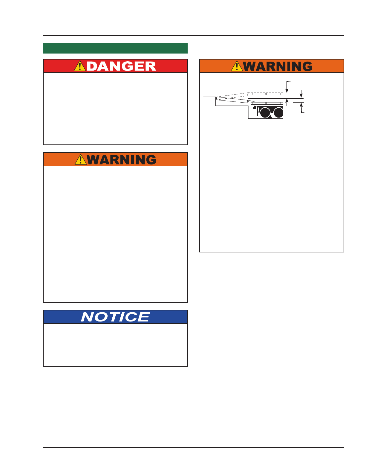
12 in. (305 mm)
12 in. (305 mm)
The MP mechanical dock leveler is designed to
compensate for a maximum ± 12 in.* (305 mm) of
height dierence between the loading dock and the
transport vehicle’s bed. DO NOT use the dock
leveler if the transport vehicle’s bed is more than 12
in. (305 mm) higher or lower than the dock oor.
*Service height may vary with design specications.
DO NOT overload the dock leveler.
DO NOT operate any equipment while under the
inuence of alcohol or drugs.
DO NOT leave equipment or material unattended
on the dock leveler.
Make sure platform lip rests on the transport vehicle
bed with at least 4 in. (102 mm) of overlap.
Maintain a safe distance from side edges of leveler
during the loading/unloading process.
When activating the leveler, always pull swiftly AND
hold the platform release ring until the platform is at
the full raised position. Releasing the ring while the
platform is still raising may result in damage to the
equipment.
4111-0019 — June 2019
© 2019 Systems, LLC
21
Page 24
OPERATION
Operating Instructions
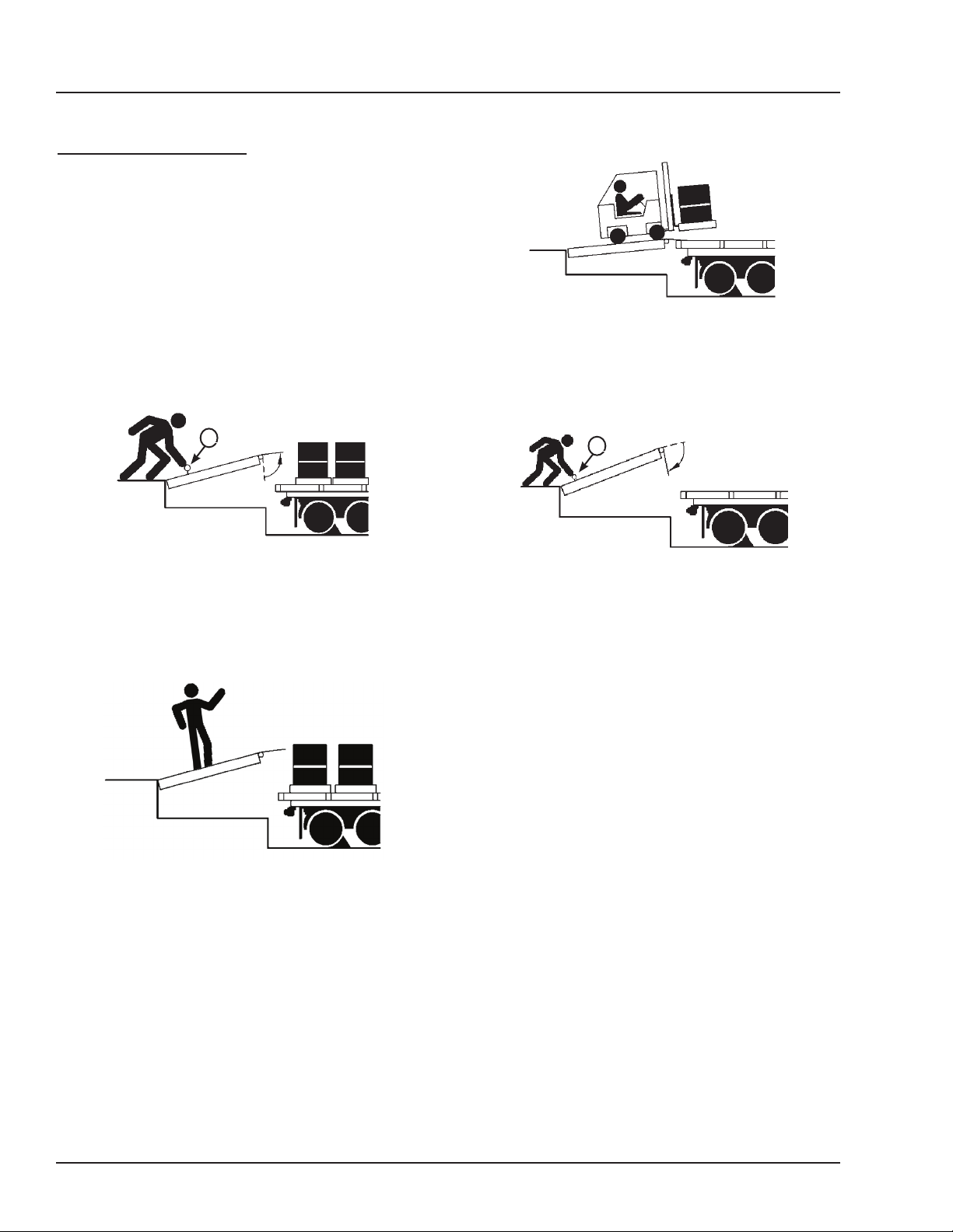
Ramp Loading/Unloading
1. Before activating dock leveler, check to make sure
the transport vehicle is positioned squarely against
dock bumpers. Ensure lip will avoid contact with
transport vehicle frame, sides and cargo during dock
leveler activation. If contact is likely or observed,
reposition transport vehicle.
2. Instruct driver to remain at the dock until the
loading or unloading process has been completed.
Figure 17
3. Chock the transport vehicle wheels, or use a
vehicle restraint if available.
A
Figure 15
4. Raise the platform by pulling and holding the
platform release ring (A).
5. Hold the release ring until the platform is at the
fully-raised position and lip is fully extended.
8. Proceed with loading or unloading the transport
vehicle.
A
Figure 18
9. When the loading or unloading process has been
completed, return platform to cross-traffic (stored)
position as follows:
a. Raise the platform to the full-raised position by
pulling and holding the platform release ring (A).
b. Lower platform by slowly walking out onto the
platform allowing time for the lip to fully fold and
clear the transport vehicle. Continue walking out
on platform until platform lowers to the crosstraffic position (lip engages in the lip keepers).
Figure 16
6. Walk out onto the platform. The platform will lower
until the lip rests on the transport vehicle bed.
7. Make sure that the lip is fully extended and
supported on the transport vehicle along the entire
width of the platform with at least 4 in. (102 mm) of
lip contacting the transport vehicle bed.
22
10. Remove chocks from transport vehicle wheels, or
release the vehicle restraint if used.
11. Indicate to driver that the transport vehicle may
leave the dock.
4111-0019 — June 2019
© 2019 Systems, LLC
Page 25
Operating Instructions (continued)
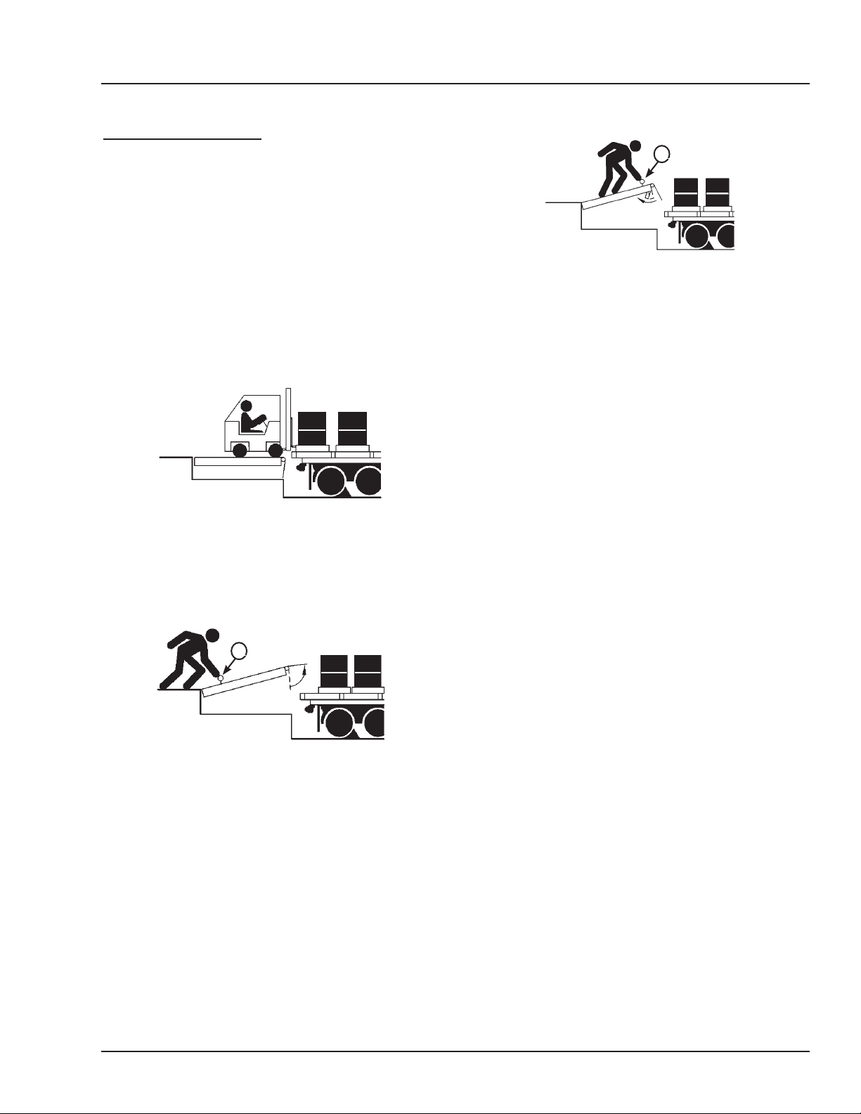
End Loading/Unloading
1. Before activating dock leveler, check to make sure
the transport vehicle is positioned squarely against
dock bumpers. Ensure lip will avoid contact with
transport vehicle frame, sides and cargo during dock
leveler activation. If contact is likely or observed,
reposition transport vehicle.
2. Instruct driver to remain at the dock until the
loading or unloading process has been completed.
3. Chock the transport vehicle wheels, or use a
vehicle restraint if available.
Figure 19
OPERATION
B
Figure 21
6. Slowly walk the platform down allowing enough
time for the lip to fold. Just before the platform
reaches the cross-traffic position, pull and hold the
safety leg retract pull ring (B, located in a recess
at front of the platform). The platform will continue
lowering to the full below dock position.
7. Proceed with loading or unloading.
Note: When end unloading is nished and access
to the rest of the transport vehicle is still required,
the platform lip will need to be extended. See Ramp
Loading/Unloading Instructions on page 22 for further
instructions.
4. If transport vehicle bed is at or above dock oor
level, leave leveler at the cross-trac position and
proceed with loading or unloading. If transport vehicle
bed is below the dock level, continue with Step 5.
A
Figure 20
5. Pull and hold the platform release ring (A) until
the platform is at the fully-raised position.
8. When loading or unloading is finished, raise
the platform to the full-raised position by pulling
and holding the platform release ring. Slowly walk
the platform down, allowing enough time for the lip
to fold. The platform will lower to the cross-traffic
position (lip engages in the lip keepers).
9. Remove chocks from transport vehicle wheels, or
release the vehicle restraint if used.
10. Indicate to driver that the transport vehicle may
leave the dock.
4111-0019 — June 2019
© 2019 Systems, LLC
23
Page 26
MAINTENANCE
Maintenance Precautions
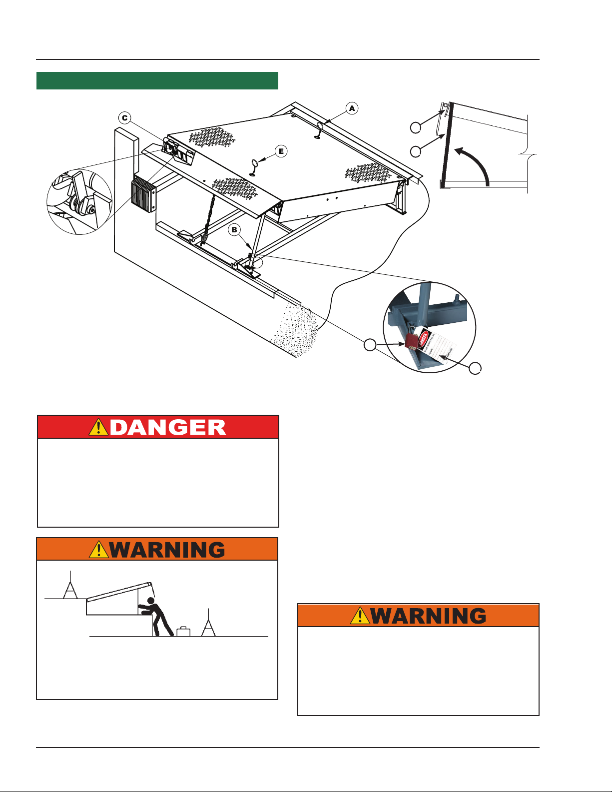
D
B
Figure 25
A - Platform Release Ring
B - Maintenance Prop
C - Lip Maintenance Prop
D - Platform Header
It is recommended and good safety practice to use
an additional means to support the dock platform
and lip anytime when physically working in front of
or under the dock leveler. This additional means
may include, but is not limited to a boom truck, fork
truck, stabilizing bar or equivalent.
Figure 24
E - Safety Leg Pull Chain
F - Lock Out Device
Whenever maintenance is to be performed under
the dock leveler platform, support the platform with
maintenance prop (B). Position the maintenance
prop behind front header plate (D) while staying clear
of the lip. Lock the maintenance prop in the service
(upright) position using an OSHA approved lockout
device* (F) and tag out device* (G). See Figures 24
and 25.
Only the person servicing the equipment should have
the capability to remove the lockout devices. The tag
out devices* must inform that repairs are in process
and clearly state who is responsible for the lockout
condition.
F
G
G - Tag Out Device
Always post safety warnings and barricade the
work area at dock level and ground level to prevent
unauthorized use of the unit before maintenance is
complete.
* Refer to OSHA regulations 1910.146. Conned Space and 1910.147. Lockout/Tagout
24
A hard hat or other applicable head protection
should always be worn when working under or
around a dock leveler.
Always stand clear of platform lip when working in
front of the dock leveler.
4111-0019 — June 2019
© 2019 Systems, LLC
Page 27
Periodic Maintenance
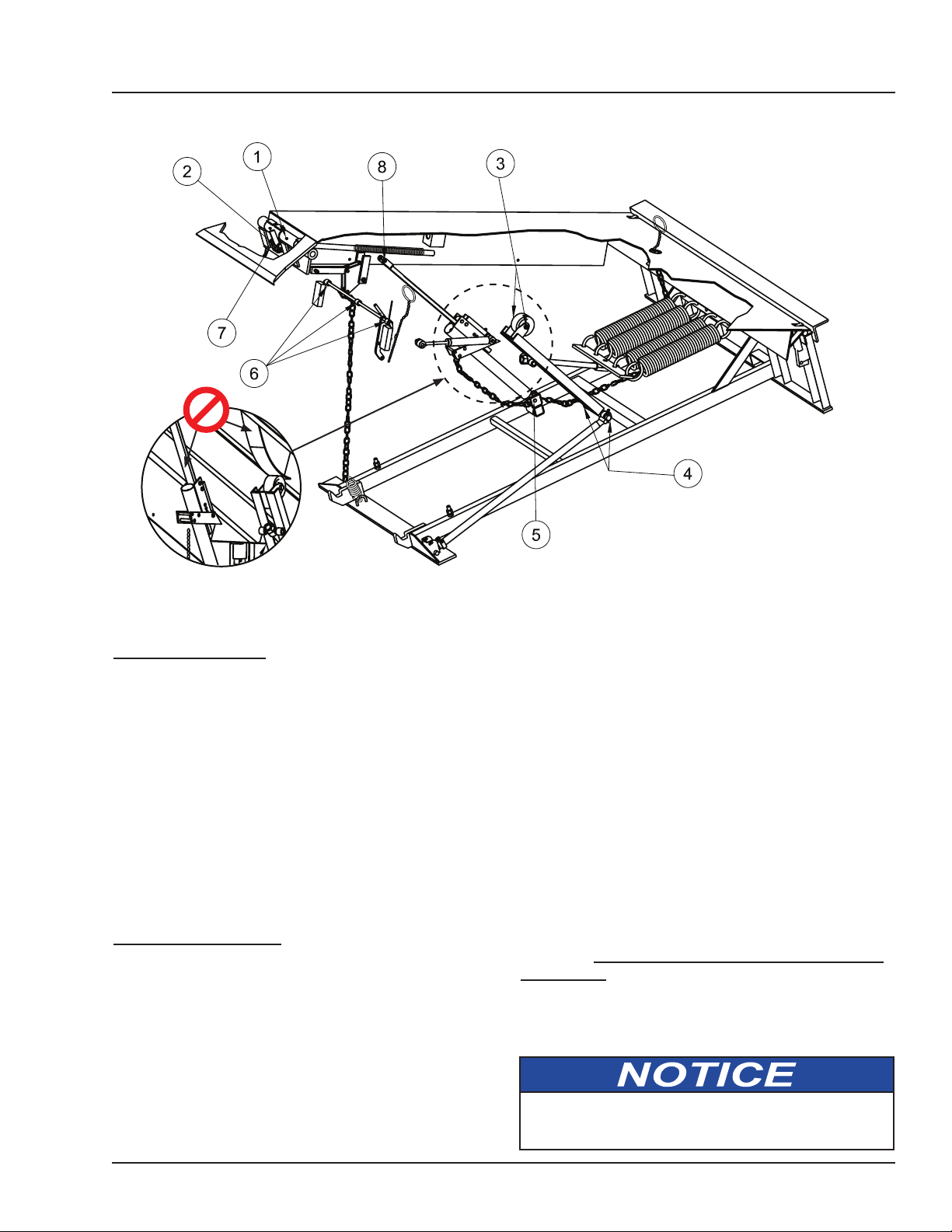
Grease
MAINTENANCE
1 — Lip Hinge Grease Fittings
2 — Lip Maintenance Prop Pivot
3 — Lift Arm Roller Bushing
4 — Lift Arm Pivot
5 — Hold-Down Pivot/Pulley
6 — Safety Leg Linkage Pivots
Weekly Maintenance
• Operate the dock leveler through the complete
operating cycle to maintain lubrication.
Note: To thoroughly inspect the platform hinge area,
put the platform in the full below-dock position.
• Inspect the platform hinge and the lip hinge areas.
The hinge areas must be kept free of dirt and
debris. Build-up of foreign material in the hinge
areas will cause abnormal operation.
• Inspect warning decals and placards. Replace if
damaged or missing.
Quarterly Maintenance
• Complete Weekly Maintenance.
• Inspect the following for damage/abnormal wear:
• Check welds for cracks.
• Lift arm pins and mounting holes.
• Lip hinge pins and rear hinge pins.
• Check toe guards for free movement.
• Bumpers for more than 1” of wear. Replace
worn, loose, damaged or missing bumpers.
• Side and rear weather seals.
Figure 26
7 — Lip Lift Assist Pin
8 — Hold Down-to-Platform Pin
• Lubricate the following areas with light weight
machine oil (see Figure 26):
(2) — Lip maintenance prop pivot
(5) — Hold-down pivot/pulley
(6) — Safety leg linkage pivots
(8) — Hold-down to platform pin
• Lubricate the following areas with white lithium
grease:
(1) — Lip hinge area
(3) — Lift arm roller bushing
(4) — Lift arm pivot
(7) — Lip assist pin
Note: Apply grease to lip hinge grease ttings if
equipped. Do not put grease or oil on the ratchet
bar or cam!
Failure to properly lubricate the dock leveler will
cause abnormal operation of the leveler.
4111-0019 — June 2019
© 2019 Systems, LLC
25
Page 28
ADJUSTMENTS
Adjust Main Spring & Lip Assist Spring Tension
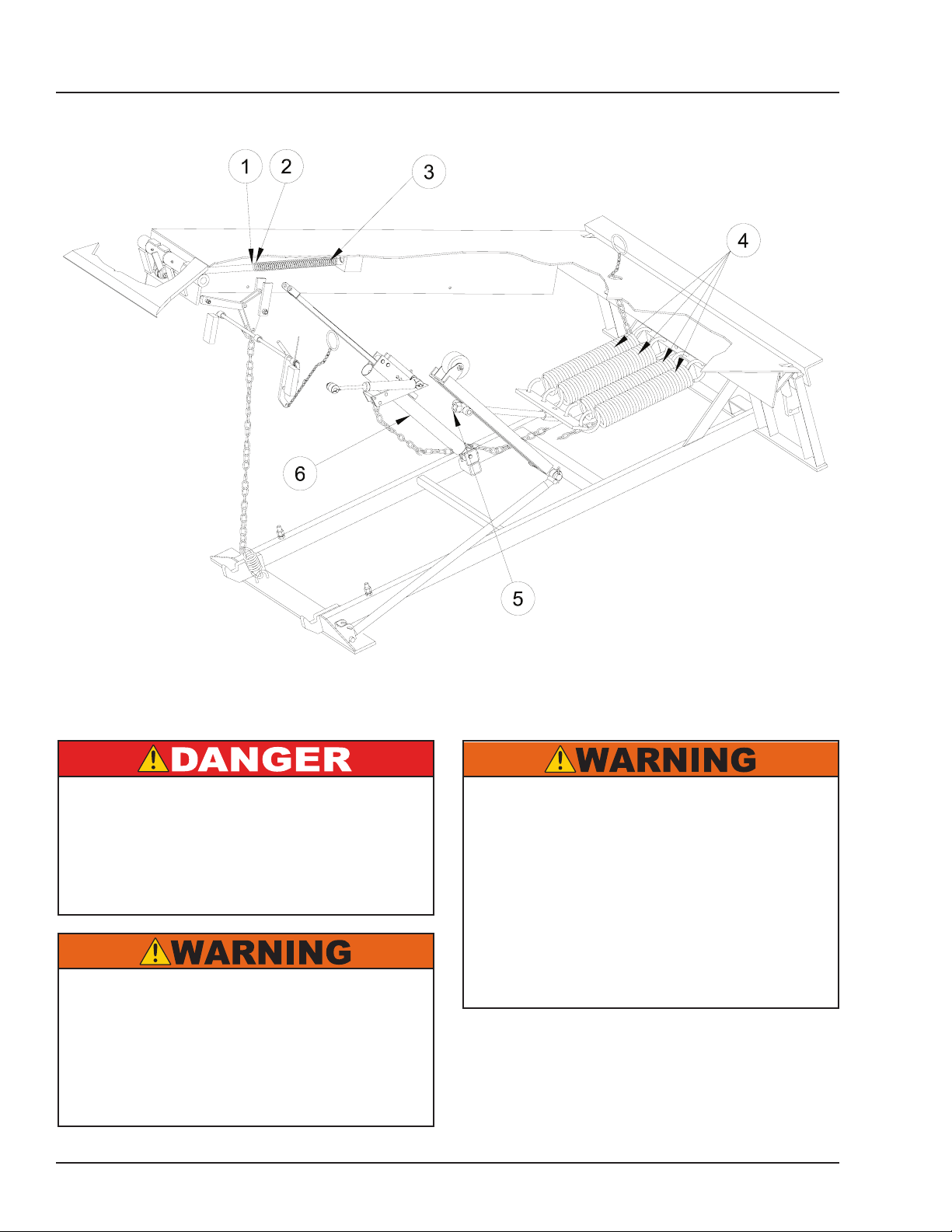
1 — Jam Nut
2 — Adjustable Nut
3 — Lip Assist Spring
4— Lift Springs
It is recommended and good safety practice to use
an additional means to support the dock platform
and lip anytime when physically working in front of
or under the dock leveler. This additional means
may include, but is not limited to a boom truck, fork
truck, stabilizing bar or equivalent.
The maintenance prop MUST be in the service
position when working under the dock leveler.
For maximum protection, use an OSHA approved
locking device to lock the maintenance prop in
the service position. Only the person servicing
the equipment should have the key to unlock the
maintenance prop.
Figure 27
5 — Lift Spring Bolt
6 — Hold-Down Mechanism
Always post safety warnings and barricade the
work area at dock level and ground level to prevent
unauthorized use of the dock leveler before
maintenance is complete.
A hard hat or other applicable head protection
should always be worn when working under or
around a dock leveler.
Always stand clear of platform lip when working in
front of the dock leveler.
26
4111-0019 — June 2019
© 2019 Systems, LLC
Page 29
Adjust Main Spring & Lip Assist Spring Tension (continued)
3. After lift spring adjustment is completed, check
operation of the lip:
If the platform does not rise fully on its own, it may
be necessary to use an external lifting device. Use
a lifting device with the appropriate lifting capacity to
safely raise the platform. Make sure to engage and
pin the platform maintenance prop after raising the
platform.
When using an external lifting device to raise the
platform, make sure hold-down mechanism (6) is
disengaged. Pull and hold platform release ring
during the lifting process to avoid shearing the
ratchet pawl and ratchet bar teeth.
• If the lip folds before the platform can be walked
down, tension of lip assist spring (3) may be set
too low.
• If the lip does not fold fully or takes too long to
fold, tension of lip assist spring (3) may be set
too high.
4. Adjust lip assist spring tension as follows:
Note: Use two-turn increments when adjusting
lip assist spring (3). Check lip operation after
each adjustment. Repeat until proper operation is
obtained.
ADJUSTMENTS
If the platform does not rise fully and/or lip does not
extend fully, the main lift spring tension may be set
too low.
If the platform cannot be walked down or is difficult
to walk down, the main lift spring tension may be set
too high.
Note: Adjusting the tension of lift springs (4) usually
requires that the lip assist spring (3) also be adjusted.
1. Raise the platform and engage the platform
maintenance prop. Pin the maintenance prop in the
service position using attached pin device.
2. Adjust tension of lift springs (4) as follows:
Note: Use 1/2 turn increments when adjusting lift
spring bolt (5).Turn clockwise to increase tension
and counterclockwise to decrease tension. Check
platform operation after each adjustment. Repeat
until proper operation is obtained.
• To increase lift spring tension, turn lift spring bolt
(5) clockwise.
a. Loosen jam nut (1).
b. To increase spring compression, turn nut (2)
clockwise.
c. To decrease spring compression, turn nut (2)
counterclockwise.
d. Tighten jam nut.
5. Recheck operation of platform and lip. Readjust
lift spring tension and lip assist spring tension until
proper operation is obtained.
• To decrease lift spring tension, turn lift spring bolt
(5) counterclockwise.
4111-0019 — June 2019
© 2019 Systems, LLC
27
Page 30
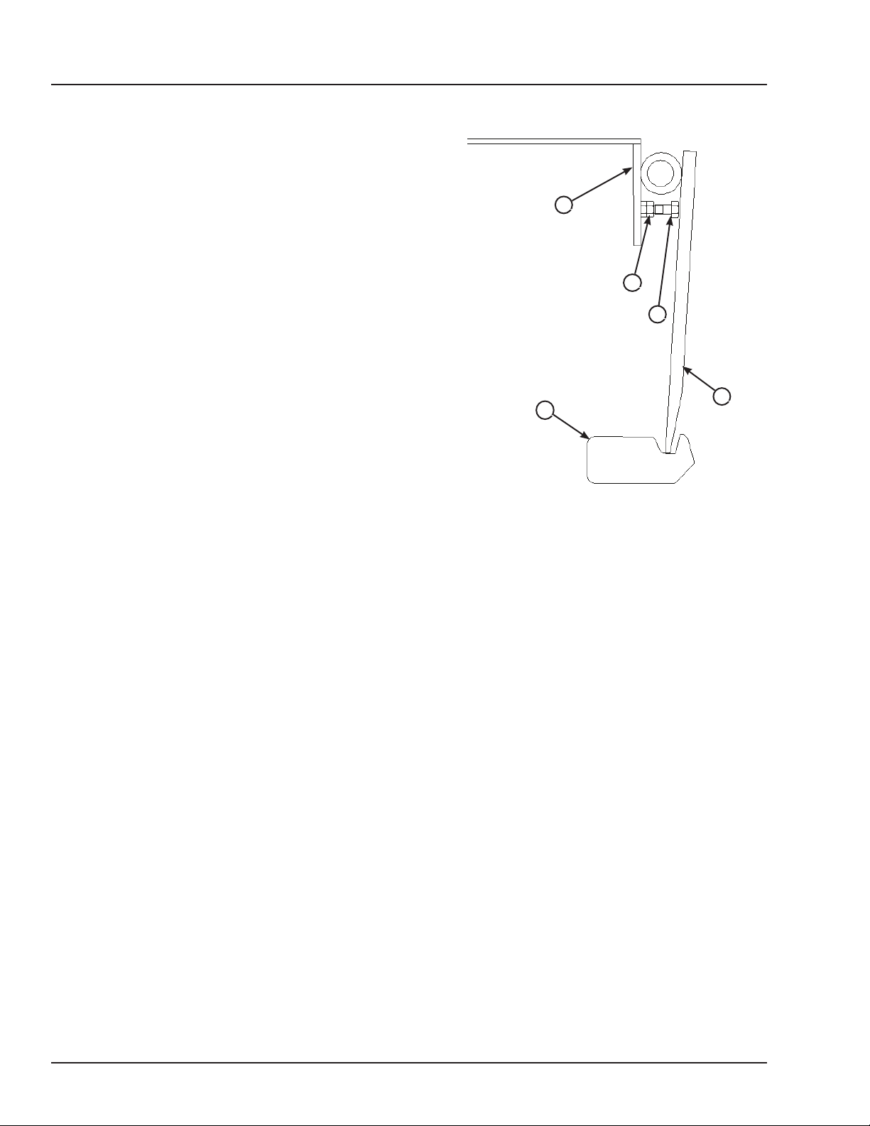
ADJUSTMENTS
Adjust Lip Stop Bolt
When at rest, lip (E) should be fully resting on the lip
keepers (D) and at the lowest part of the lip keepers.
If lip is not resting properly in the lip keepers, perform
the following adjustment:
1. Fully raise the platform and engage the
maintenance prop in the service position. Manually
raise the lip and engage lip maintenance prop (not
shown).
A
B
2. Loosen jam nut (B).
3. Adjust stop bolt (C) as necessary.
• Turn stop bolt “in” (clockwise) to allow lip to fold
closer to platform (A).
• Turn stop bolt “out” (counterclockwise) to hold lip
further away from platform (A).
4. Tighten jam nut (B).
5. Disengage lip maintenance prop.
6. Walk platform down to cross-traffic (stored)
position.
7. Check lip position in both keepers. Repeat
procedure if necessary.
A— Platform
B— Jam Nut
C— Stop Bolt
C
E
D
Figure 28
D — Lip Keeper
E — Lip
28
4111-0019 — June 2019
© 2019 Systems, LLC
Page 31

ADJUSTMENTS
4111-0019 — June 2019
© 2019 Systems, LLC
This page intentionally left blank.
29
Page 32
TROUBLESHOOTING
It is recommended and good safety practice to use
an additional means to support the dock platform
and lip anytime when physically working in front of
or under the dock leveler. This additional means
may include, but is not limited to a boom truck, fork
truck, stabilizing bar or equivalent.
The maintenance prop MUST be in the service
position when working under the dock leveler.
For maximum protection, use an OSHA approved
locking device to lock the maintenance prop in
the service position. Only the person servicing
the equipment should have the key to unlock the
maintenance prop.
Symptom Possible Cause Solution
Always post safety warnings and barricade the
work area at dock level and ground level to prevent
unauthorized use of the dock leveler before
maintenance is complete.
A hard hat or other applicable head protection
should always be worn when working under or
around a dock leveler.
Always stand clear of platform lip when working in
front of the dock leveler.
Remove object(s) from platform.
Platform does not rise.
Platform rises slowly or
does not rise to the full
raised position.
Heavy object(s) on platform.
Disconnected or broken
release chain.
Dock leveler binds.
Heavy object(s) on platform.
Dock leveler binds.
Insucient main spring
tension.
Note: For safety reasons, the dock leveler is
designed to lift only the platform’s own weight.
Connect or replace release chain.
Check for visible obstructions that could cause
binding. Remove obstructions. If no obstructions
found, contact Systems, LLC Technical Services.
Remove object(s) from platform.
Note: For safety reasons, the dock leveler is
designed to lift only the platform’s own weight.
Check for visible obstructions that could cause
binding. Remove obstructions. If no obstructions
found, contact Systems, LLC Technical Services.
Increase tension on main springs. See pages 26-27
for instructions.
30
Damaged or worn
hold-down mechanism.
Inspect and clean hold-down mechanism. Replace if
damaged or faulty.
4111-0019 — June 2019
© 2019 Systems, LLC
Page 33
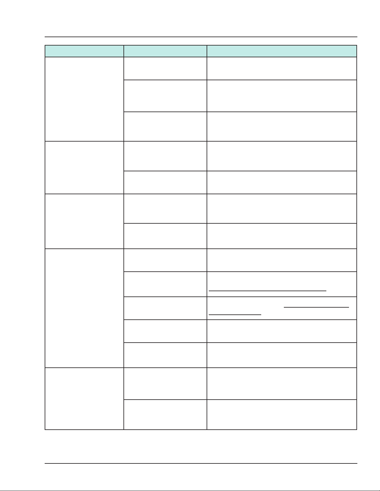
TROUBLESHOOTING
Symptom Possible Cause Solution
Platform rises to full
height, but lip does not
fully extend.
Platform does not lower
when operator walks out
onto the platform.
Lip folds too fast during
normal walk-down.
Lip assist chain
disconnected or broken.
Insufficient main spring
tension.
Insufficient lip assist force.
Excessive main spring
tension.
Damaged or worn holddown mechanism.
Insufficient lip assist force.
Disconnected, worn, or
broken gas shock.
Connect or replace lip assist chain.
Increase tension on main springs. See pages 26-27
for instructions.
Increase tension on lip assist spring. See pages
26-27 for instructions.
Reduce main spring tension. See pages 26-27 for
instructions.
Inspect and clean hold-down mechanism. Replace if
damaged or faulty.
Increase tension on lip assist spring. See pages
26-27 for instructions.
Inspect gas shock. Replace if damaged or faulty.
Platform does not stay
down.
Lip does not fold after
truck departs.
Binding or stuck release
chain.
Dirt impacted in ratchet bar
teeth.
Broken or damaged ratchet
assembly teeth.
Disconnected or broken
hold-down pivot pins.
Damaged or worn holddown mechanism.
Lip hinge binding due to lack
of lubrication
Excessive lip assist force.
Check for visible obstructions that could cause
binding. Remove obstructions.
Inspect and clean ratchet bar and ratchet pawl teeth.
DO NOT lubricate the ratchet assembly.
Replace ratchet assembly. DO NOT lubricate the
ratchet assembly.
Connect or replace hold-down pivot pins.
Inspect and clean hold-down mechanism. Replace if
damaged or faulty.
Grease lip hinge. See page 25 for instructions.
Decrease tension on lip assist spring. See pages
26-27 for instructions.
If additional troubleshooting assistance is required, contact Systems, LLC
Technical Services with equipment serial number or customer order number (CO#).
Technical Service at 800-643-5424 or [email protected]
4111-0019 — June 2019
© 2019 Systems, LLC
31
Page 34
NOTES
REVISIONS
EN REV
DESCRIPTION DATE
XX-XXX
-
ORIGINAL ISSUE
PARTS
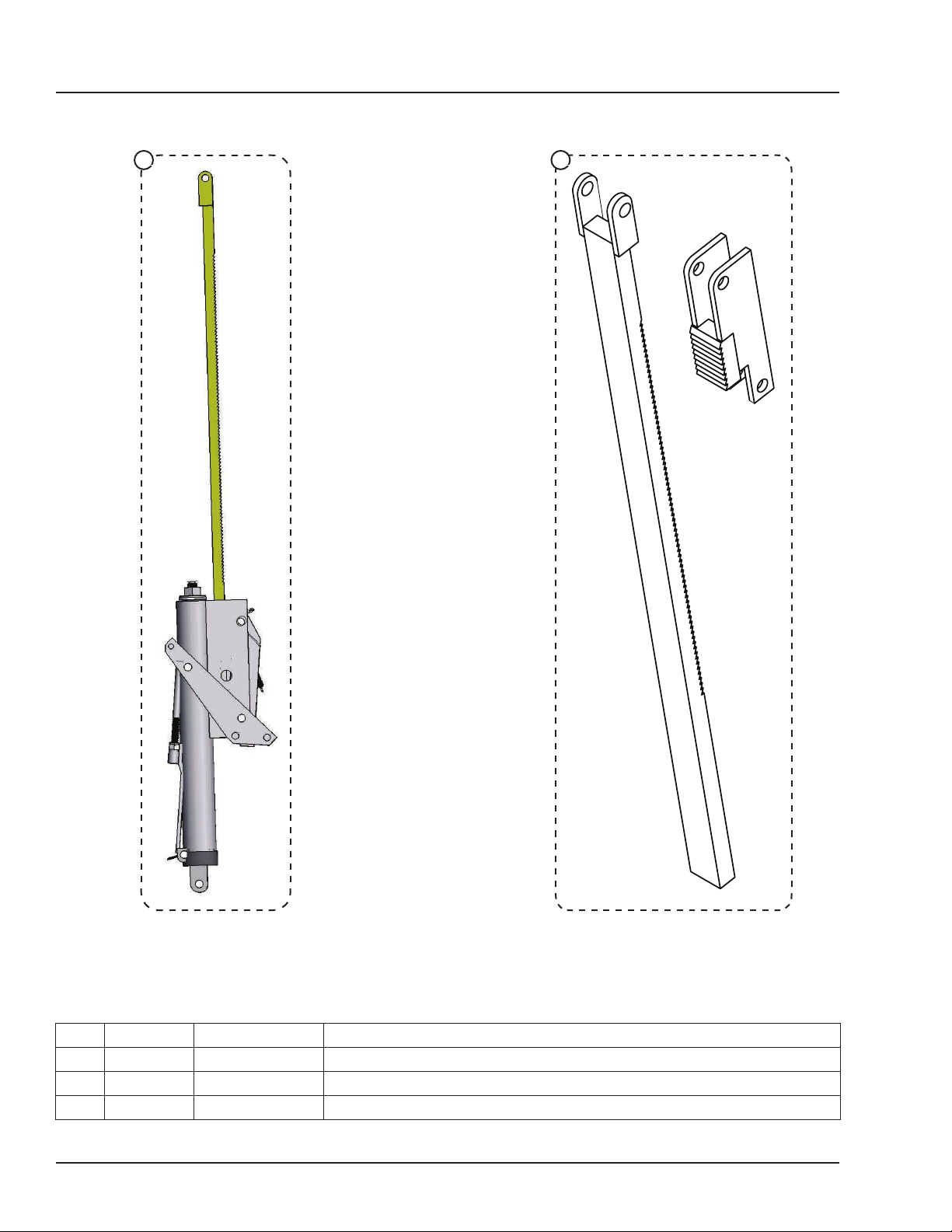
Hold-Down Components
BA
Item Quantity Part Number Description
A 1 M502.089 Hold Down, Complete (ts 1990-present)
B 1 M512.986 Ratchet and Pawl Kit (for M502.089)
NS* 1 M512.988 Release Arm Spring (for M502.089)
*
NS = Not Shown
32
4111-0019 — June 2019
© 2019 Systems, LLC
Page 35
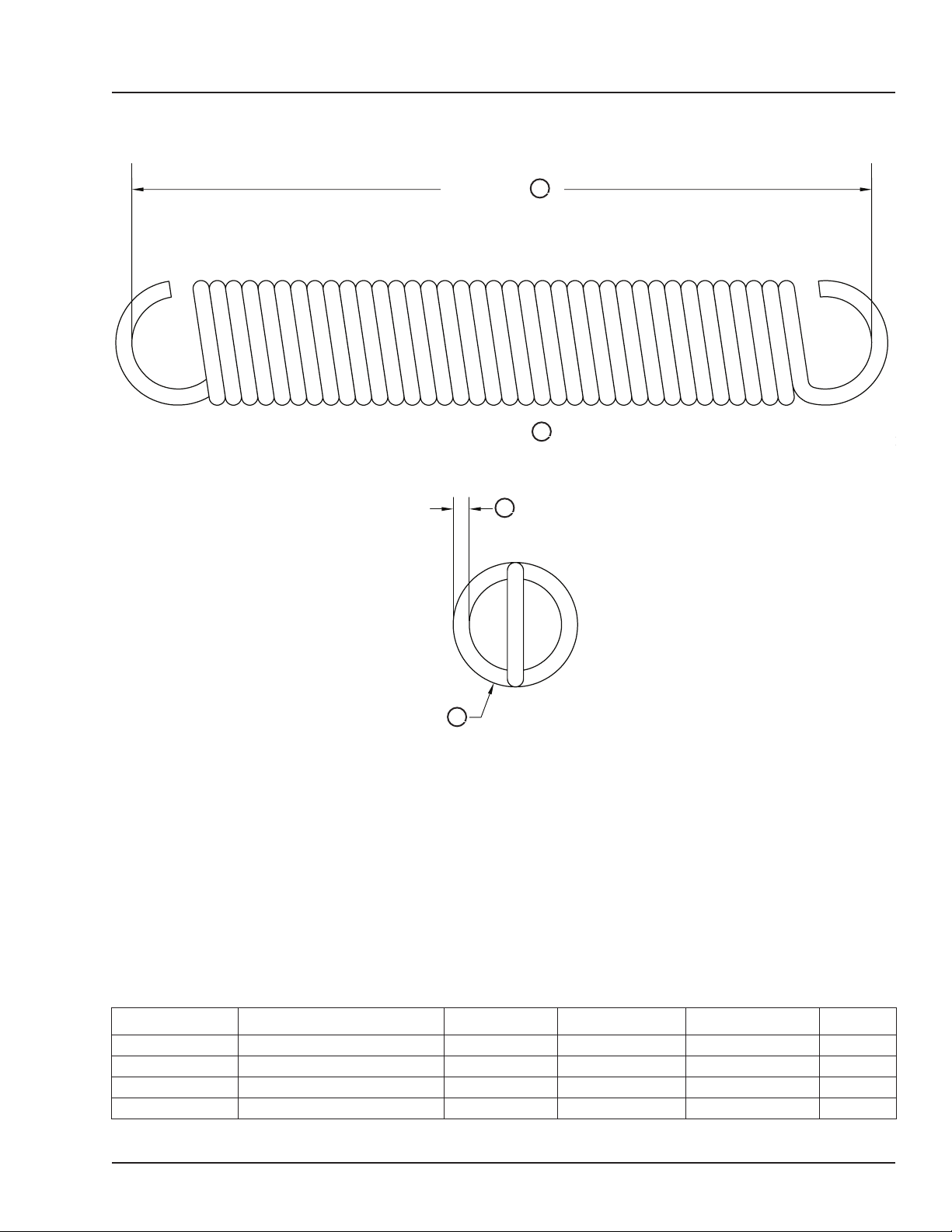
Main Lift Springs
PARTS
Length
Coils
C
A
D
Wire Diameter
Outer Diameter
Part Number* Description Length (A) O.D. (B) Wire Dia. (C) Coils (D)
DOTH-2570 Main Lift Spring - Blue 20” (508mm) 3.468” (88mm) .406” (10mm) 38
DOTH-2574 Main Lift Spring - Red 21” (533mm) 4.750” (121mm) .531” (13mm) 26
DOTH-2576 Main Lift Spring - Black 23” (584mm) 3.875” (98mm) .500” (12mm) 37
DOTH-2578 Main Lift Spring - Yellow 23” (584mm) 4.700” (119mm) .594” (15mm) 30
*
Provide dock leveler serial number, platform size, lip size and capacity when e-mailing, calling or faxing orders.
B
4111-0019 — June 2019
© 2019 Systems, LLC
33
Page 36
PARTS
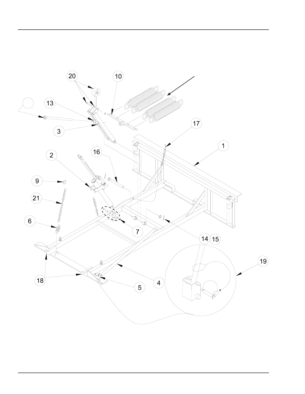
Frame Components
10
See Page 33
34
4111-0019 — June 2019
© 2019 Systems, LLC
Page 37
Frame Components
Item Quantity Part Number Description
1 1 8435-____
2 1 M502.089 Hold Down, Complete (ts 1990-present)
3
1 DOTP-6424
1 DOTP-6423
4 1 9224-____
5 1 9221-____
6 1 DOTH-2555 Spring, Snubber
2101-0361 Bolt, Shoulder, 1/2 x 2-1/4, 3/8-16
DFRA-0350 Roller, Release Chain
7 1
DOTH-2210 Washer, Flat, 1/2”
2101-0060 Washer, Flat, 3/8” SAE
DOTH-2131 Lock Nut, Nylon, 3/8-16
9 1 DOTH-2416 Lap Link, 3/16” x 1”
10 1
DFRA-0326
DFRA-0327
13 2 DOTH-2218 Washer, Flat,1-1/16” ID x 2” OD
14 2 DOTH-2222 Washer, Flat, 1-1/16 ID x 1-1/2 OD
15 4 DOTH-2374 Pin, Cotter, 1/8 x 1
16 1 DFRA-1205 Pin, Lift Arm, 1” x 9-1/8”
5265-0012
17 1
5265-0013
5265-0014
18 2 8432-____
19 1 9201-0006 Prop Pin & Clip
20 1 DOTH-2401 Caster Assembly, 4” OD
21 1 DPLA-2128 Chain, Lip Assist Link
*
Frame, Welded Assembly
*
Lift Arm, Short, 25” (Includes Caster Assembly)
*
Lift Arm, Long, 27” (Includes Caster Assembly)
*
Prop, Maintenance
*
Housing, Maintenance Prop
*
T-Bar and Adjusting Rod, 6’
*
T-Bar and Adjusting Rod, 8’/10’
*
Chain, Hold-Down Release, 6’
*
Chain, Hold-Down Release, 8’
*
Chain, Hold-Down Release, 10’
*
Keeper, Lip
PARTS
*
Provide dock leveler serial number, platform size, lip size and capacity when e-mailing, calling or faxing orders.
4111-0019 — June 2019
© 2019 Systems, LLC
35
Page 38
PARTS
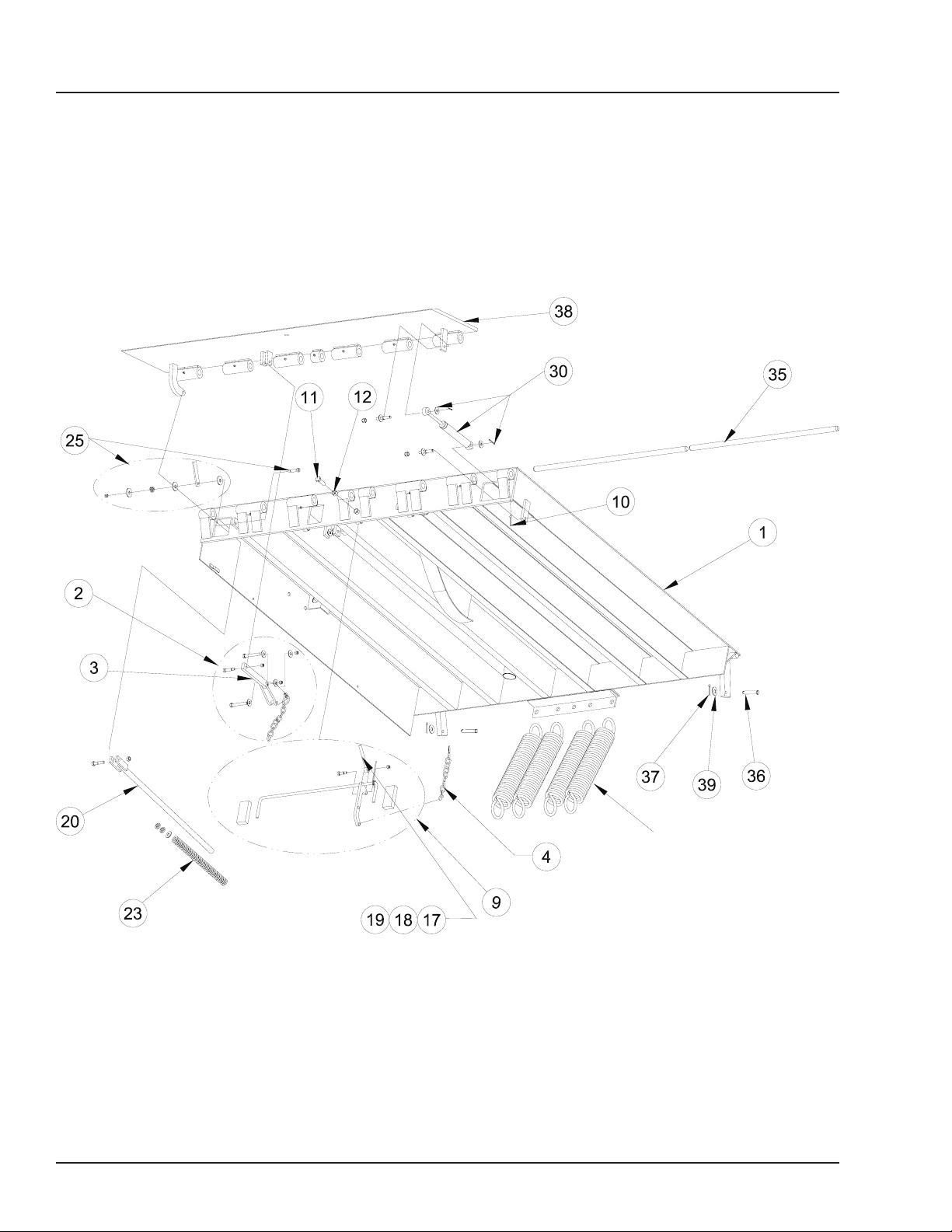
Platform Components
36
See Page 33
4111-0019 — June 2019
© 2019 Systems, LLC
Page 39

Platform Components
Item Quantity Part Number Description
1 1 9515-____
2 1 DPLA-0338 Lip Banger Assembly, Neutron (Includes Item 3)
3 1 DPLA-0341 Bar, 5/8 x 1 x 11-5/8
4 1 DPLA-0353 Below Dock Chain Assembly
9 1
DPLA-0343 Below Dock Control Assembly
DPLA-0401 Below Dock Control Assembly (6' Long Units Only)
10 2 DOTH-2382 Pin, Cotter, 1/4 x 2
11 1 DOTH-2074 Bolt, Hex, 5/8-11 UNC x 2
12 1 DOTH-2160 Nut, Hex, 5/8-11
17 1 DPLA-0360 Below Dock Control Push Rod Assembly
18 1 DOTH-2060 Bolt, Shoulder, 1/2 x 1, 3/8”-16 UNC
19 1 DOTH-2131 Lock Nut, Nylon, 3/8-16
20 1 DOTH-6406 Lip Assist Rod
23 1
DOTH-2550
DOTH-2546
25 1 9513-0091 Assembly, Lip Prop
30 1 DKIT-6465 Kit, Gas Shock w/Hardware
DPLA-2101
35 2
DPLA-2102
DPLA-2103
36 2 DOTH-2355 Pin, Clevis, 1/2 x 2-1/4 w/Hole
37 2 DOTH-2373 Cotter Pin, 1/8 x 1-1/2
38 1 0595-____
39 2 2101-0079 Washer, Flat, 1/2” SAE
*
Platform, Welded Assembly
*
Spring, Lip Assist, Standard Orange)
*
Spring, Lip Assist, Heavy Duty (Green)
*
Pin, Lip Hinge, 1” OD x 35.25
*
Pin, Lip Hinge, 1” OD x 38.25
*
Pin, Lip Hinge, 1” OD x 40.5
*
Lip, Welded Assembly
PARTS
*
Provide dock leveler serial number, platform size, lip size and capacity when e-mailing, calling or faxing orders.
4111-0019 — June 2019
© 2019 Systems, LLC
37
Page 40
PARTS
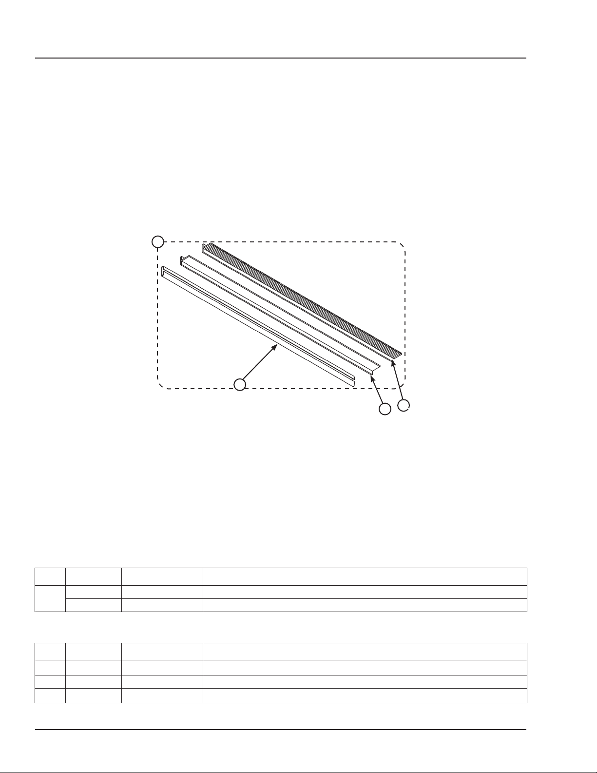
Weather Seals
A
D
Weather Seal Kits
Item Quantity Part Number Description
A
Individual Replacement Seals
Item Quantity Part Number Description
B 1 DOTH-2822 Brush Rell, 1-1/2 in. 84" Lg.
C 1 DOTH-2824 Rubber Rell, 1-1/2 in. 84" Lg.
D 1 DOTH-2840 Replacement Channel
1 DKIT-9293 Brush Kit (Includes Seal and Track), 1-1/2 in. 84" Lg. (Both Sides)
1 DKIT-9292 Rubber Kit (Includes Seal and Track), 1-1/2 in. 84" Lg. (Both Sides)
B
C
38
4111-0019 — June 2019
© 2019 Systems, LLC
Page 41
Toe Guards
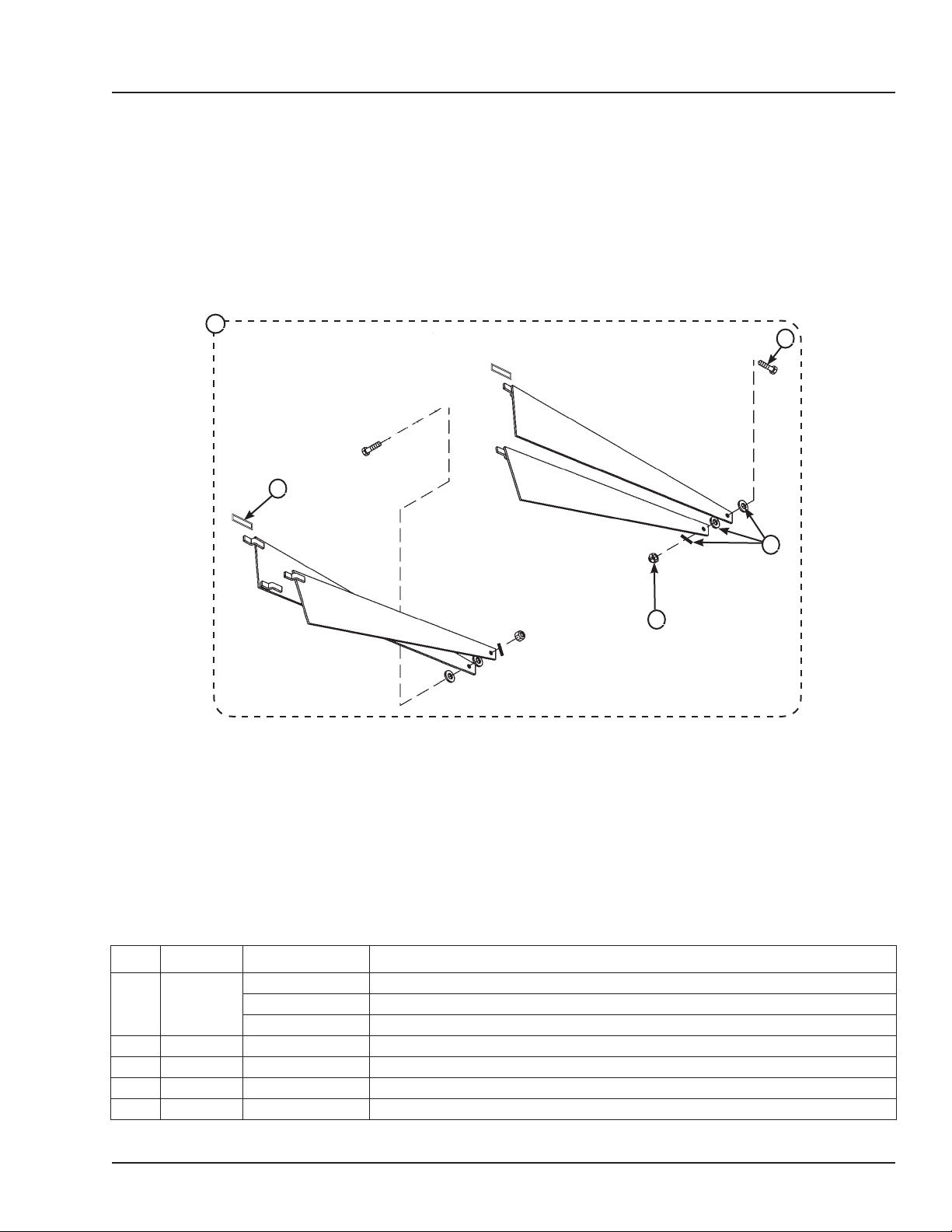
PARTS
A
E
D
B
C
Item Quantity Part Number Description
DKIT-9183* Toe Guard Kit, Sliding 6’ (Includes Both Sides)
A 1
DKIT-9184* Toe Guard Kit, Sliding 8’ (Includes Both Sides)
DKIT-9185* Toe Guard Kit, Sliding 10’ (Includes Both Sides)
B 2 DOTH-2043 Cap Screw
C 6 DOTH-2207 Washer
D 2 DOTH-2131 Lock Nut
E 2 0011-0010 Platform Mounting Tab
*
Provide dock leveler serial number and size of platform when e-mailing, calling or faxing orders.
4111-0019 — June 2019
© 2019 Systems, LLC
39
Page 42

MISCELLANEOUS
40
This page intentionally left blank.
4111-0019 — June 2019
© 2019 Systems, LLC
Page 43
Customer Information
MISCELLANEOUS
A
Figure 29
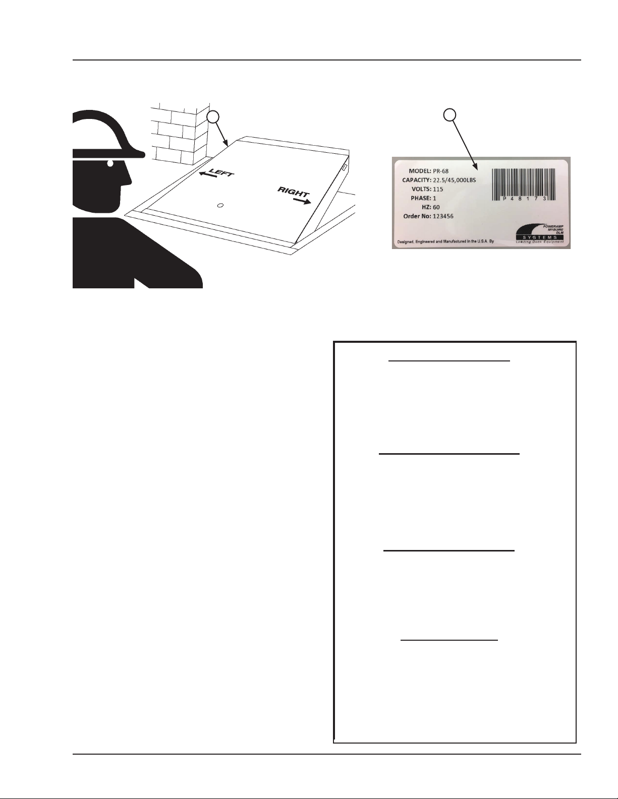
NOTE: Refer to Figure 29 for left/right orientation of dock
leveler and Figure 30 for example of decal.
The LEVELER model/serial number decal is
located on the left platform joist near the front (lip)
of dock leveler (A).
B
Figure 30
Dock Leveler Information
Model ___________________________________
Serial No. ________________________________
When you receive your new equipment, write down the
model and serial number in the form provided. This will
help ensure safe keeping of the numbers in the event
the model/serial number decal (A, B) becomes lost or
damaged.
Also, write down Systems, LLC’s order number, the
company that installed the dock leveler, and the original
owner’s name. This will all help to identify the specific dock
leveler if more information is required.
When ordering, use part numbers and description to help
identify the item ordered. Do not use “item” numbers.
These are only for locating the position of the parts. Always
give dock leveler MODEL NUMBER and/or SERIAL
NUMBER.
For service, call or contact:
Systems, LLC
P.O. Box 309
Germantown, WI 53022
Phone: (800) 643-5424
Fax: (262) 255-5917
Systems, LLC, Job No. ______________________
Vehicle Restraint Information
Model ___________________________________
Serial No. ________________________________
Systems, LLC Order No. ______________________
Original Owner Information
Name ___________________________________
Address _________________________________
________________________________
Installer Information
Name ___________________________________
Address _________________________________
_________________________________
www.loadingdocksystems.com
4111-0019 — June 2019
© 2019 Systems, LLC
Date of Installation ________________________
41
Page 44

STANDARD PRODUCT WARRANTY
SYSTEMS, LLC warrants that its products will be free from defects in design, materials and workmanship
for a period of one (1) year from the date of shipment. All claims for breach of this warranty must be made
within 30 days after the defect is or can with reasonable care, be detected. In no event shall any claim
be made more than 30 days after this warranty has expired. In order to be entitled to the benets of this
warranty, the product must have been properly installed, maintained and operated in accordance with all
manufacturer’s recommendations and/or specied design parameters and not otherwise have been subject
to abuse, misuse, misapplication, acts of nature, overloading, unauthorized repair or modication, application
in a corrosive environment or lack of maintenance. Periodic lubrication, adjustment and inspection in
accordance with all manufacturers’ recommendations are the sole responsibility of the Owner/User.
In the event of a defect, as determined by SYSTEMS LLC, covered by this warranty, SYSTEMS LLC shall
remedy such defect by repairing or replacing any defective equipment or parts, bearing the cost for the
parts, labor and transportation. This shall be exclusive remedy for all claims whether based on contract,
negligence or strict liability.
WARRANTY LIMITATIONS
THE ABOVE WARRANTIES ARE IN LIEU OF ANY OTHER WARRANTIES, WHETHER EXPRESSED OR
IMPLIED, INCLUDING BUT NOT LIMITED TO ANY IMPLIED WARRANTY OF MERCHANTABILITY OR
FITNESS FOR A PARTICULAR PURPOSE. SYSTEMS LLC AND ITS SUBSIDIARIES SHALL NOT IN ANY
EVENT BE LIABLE TO ANYONE, INCLUDING THIRD PARTIES, FOR INCIDENTAL, CONSEQUENTIAL
OR SPECIAL DAMAGES OF ANY KIND INCLUDING BUT NOT LIMITED TO, BREACH OF WARRANTY,
LOSS OF USE, LOSS OF PROFIT, INTERRUPTION OF BUSINESS OR LOSS OF GOODWILL.
PRODUCT SPECIFIC WARRANTY
“MP” SERIES LEVELER
In addition to the “Standard Product Warranty” provided with all McGuire® products, Systems LLC,
guarantees materials, components and workmanship to be free of defects for the following extended
periods:
• Structural Warranty – For an additional period of four (4) years, for parts, labor and freight,
product will carry a prorated structural warranty. This warranty specically applies to; the deck
section, lip section, frame, rear hinge assembly and front hinge assembly only. This warranty
covers structural repairs to or replacement of dock leveler in Systems LLC sole discretion and
expense including reasonable labor, materials, freight and travel. If Systems LLC determines
replacement is necessary, it will provide the original purchaser with a credit toward the purchase
of the new replacement Systems LLC product in the amount equal to the original purchase price
of the warranted product F.O.B. point of manufacture, discounted on a ve year straight line
basis by the number of years of use prior to replacement.
 Loading...