

Page 1
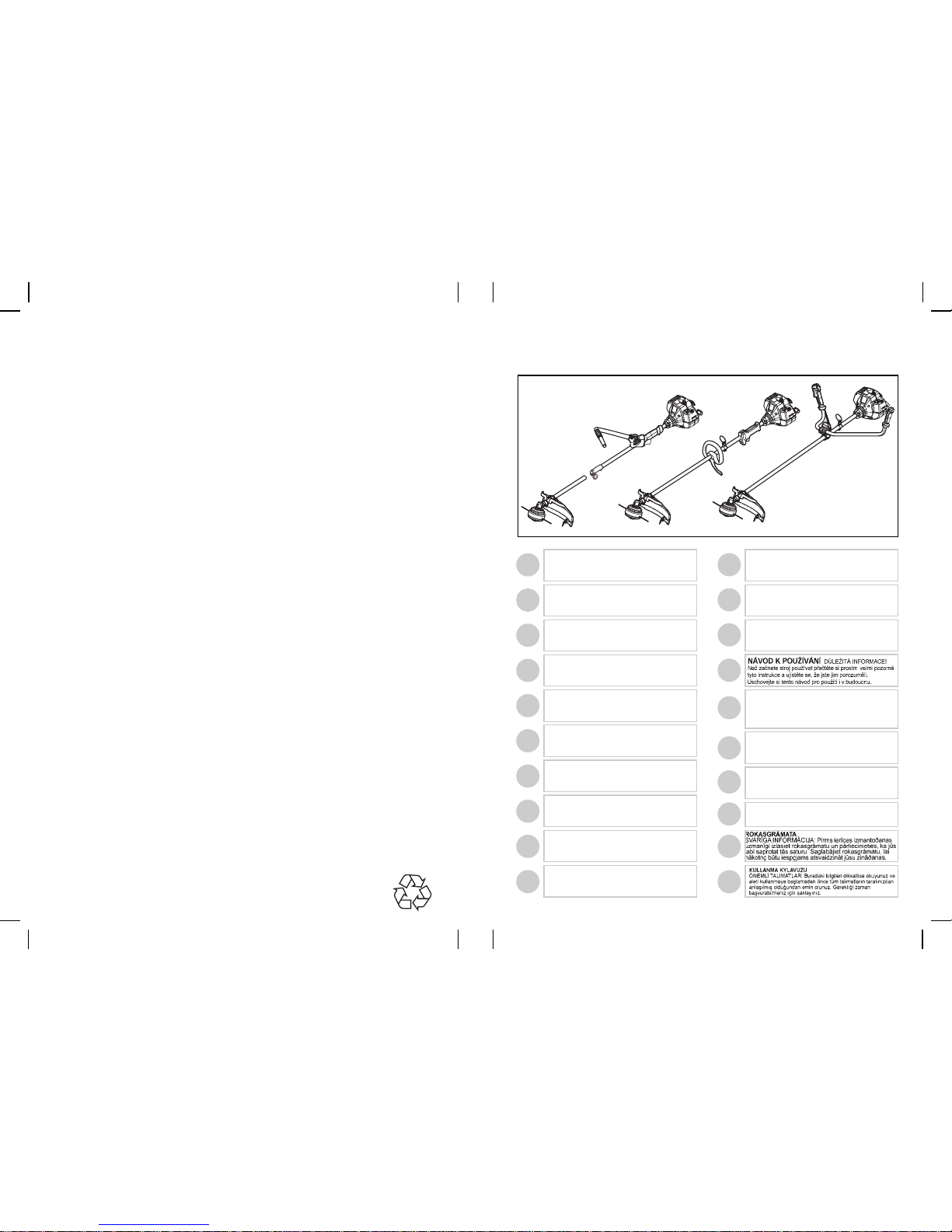
Husqvarna Outdoor Products Italia SpA
Via Como, 72
23868 Valmadrera LC
ITALIA
Phone +39 0341 203111 - Fax +39 0341 581671
PN 249954 REV.00 (11/06)
HANDLEIDING
BELANGRIJKE IMPORTANTS: Lees deze handleiding aandachtig en zorg dat u ailes begrijpt alvorens de kettingzaag te
gebrulken en be-waar ze voor toekomstige raadpleging.
BRUKERHÅNDBOK
VIKTIG INFORMASJON: Les disse anvisningene nøye
og forsikre deg om at du forstår dem før du bruker
enheten og oppbevar dem for sen-ere bruk.
BRUKSANVISNING
VIKTIG INFORMATION: Läs instruktionerna noggrant och
försäkra dig om att du förstår dem innan du använder
utrustningen och spara dem för framtida behov.
BRUGERHÅNDBOG
VIGTIGE OPLYSNINGER: Læs instruktionerne
omhyggeligt, før du bruger enheden og gemme til senere
henvisning.
LIBRETTO D’ISTRUZIONI
INFORMAZIONI IMPORTANTI: Leggere le istruzioni
attentamente e capirle bene prima di usare l’utensile.
Conservare per ulteriore consultazione.
EΓXEIPI∆IO XEIPIΣMOE
ΣHMANTIKEΣ
ΠΛHPOΦOPIEΣ: ∆ιαβάστε πρoσεxτιxά αvτές τις οδηγίες
xαι Φρovτίστε vα τις xαταvoήσετε αvτ& τo µηχάvηµα xαι
Φuλάξτε το για vα το σuµβοuλεύεστε στο µέλλοv.
OHJEKIRJA
TÄRKEÄÄ TIETOA: Lue nämä ohjeet huolellisesti ja
varmista, että olet ymmärtänyt ne, ennen kuin alat käyttää
tätä laitetta ja säilytä myöhempää tarvetta varten.
HASZNÁLATI ÚTMUTATÓ
Jótállást vállalni csak rendeltetésszerüen használatba vett
gépekre tudunk. Kérj ü hogy a gép használatba vétele elött
gondosan olvassa el a kezelési utasításokat.
GB
FI
NO
GR
HU
IT
FR
DE
ES
NL
SE
DK
INSTRUCTION MANUAL
IMPORTANT INFORMATION: Please read these instructions carefully and make sure you understand them before using this unit.
Retain these instructions for future reference.
MANUEL D’INSTRUCTIONS
RENSEIGNEMENTS
IMPORTANTS: Avant d’utiliser cet appareil, veuillez lire atentivement les instructions et assurez-vous de les avoir comprises. Conservez les instructions pour référence ultérieure.
BETRIEBSANWEISUNG WICHTIGE INFORMATION:
Lesen Sie diese Hinweise zur Handha-bung des Geräts aufmerksam durch. Verwenden Sie es erst, wenn Sie sicher sind, daß Sie
alle Anweisungen verstanden haben und gut aufbewahren.
MANUAL DE INSTRUCCIONES
INFORMACIÓN IMPORTANTE: Lea atentamente las instrucciones y asegúrese de entenderlas antes de utilizar esta aparato. Conserve las instrucciones para la referencia en el futuro.
ИНCTPYKЦИИ
BAЖHЫE CBEДEHИЯ:
Bнимaтeльнo пpoчитать инстрyкции и хрoщo их
пoнять, пepeд тeм как пoльзoвaтьcя блoкoм.
Хpaнить инcтpyкции для дaльнейшиx кoнcyльтаций.
KASUTUSJUHEND
TÂHTIS INFORMATSIOON: Lugege
kasutusjuhend enne seadme kasutamist kindlasti põhjalikult
läbi ning veenduge, et olete kõigest täpselt aru saanud.
CZ
EE
PT
MANUAL DO OPERADOR
INFORMAÇÕES IMPORTANTES: Queira ler cuidadosamente estas instruções e tenha certeza de entendë las
antes de usar a serra e guarde para consulta futura.
LV
TR
SK
PL
RU
NÁVOD NA OBSLUHU Dôleæitá informácia: Pred
pouæitím stroja si starostlivo preËítajte tento návod na
obsluhu a uistite sa æe ste mu dôkladne porozumeli.
Návod starostlivo uschovajte pre potrebu v budúcnosti.
INSTRUKCJA OBS≥UGI
Gwarancja traci waΩnoß∫ w przypadku uΩywania
urzådzenia do celów innych niΩ wymienione w instrukcji
obs≤ugi. Prosimy o uwaΩne przeczytanie instrukcji oraz o
stoowanie si™ do zalece~ i wskazówek w niej zawartych.
Page 2
A
B1
B5
B8
B2
B6
B9
B3
B7
B10
B4
D
E1
F1 F2 F3 F4
F5 F6
E2
1 ltr
20 cm
3
5 100
10 200
15 300
20 400
50:1
2%
Partner oil
1 ltr
25 cm
3
4 100
5 125
10 250
20 500
40:1
2,5%
2 Strokes
engine totally
synthetic oil or
McCulloch oil
Page 3
G1 G2 G3
H1 H2
C
H3 H4 H5
I L1 L2
L3
N1 N2
O
15 cm
15 cm
M
L4 L5
0,095”
2.4mm
197”
5000mm
4T
9”
230 mm
4T
10”
255 mm
8T
10”
255mm
8T
9”
230mm
531025001
538249155
531024905
538249155
531024902
538249155
531024906
538249155
531024903
538249155
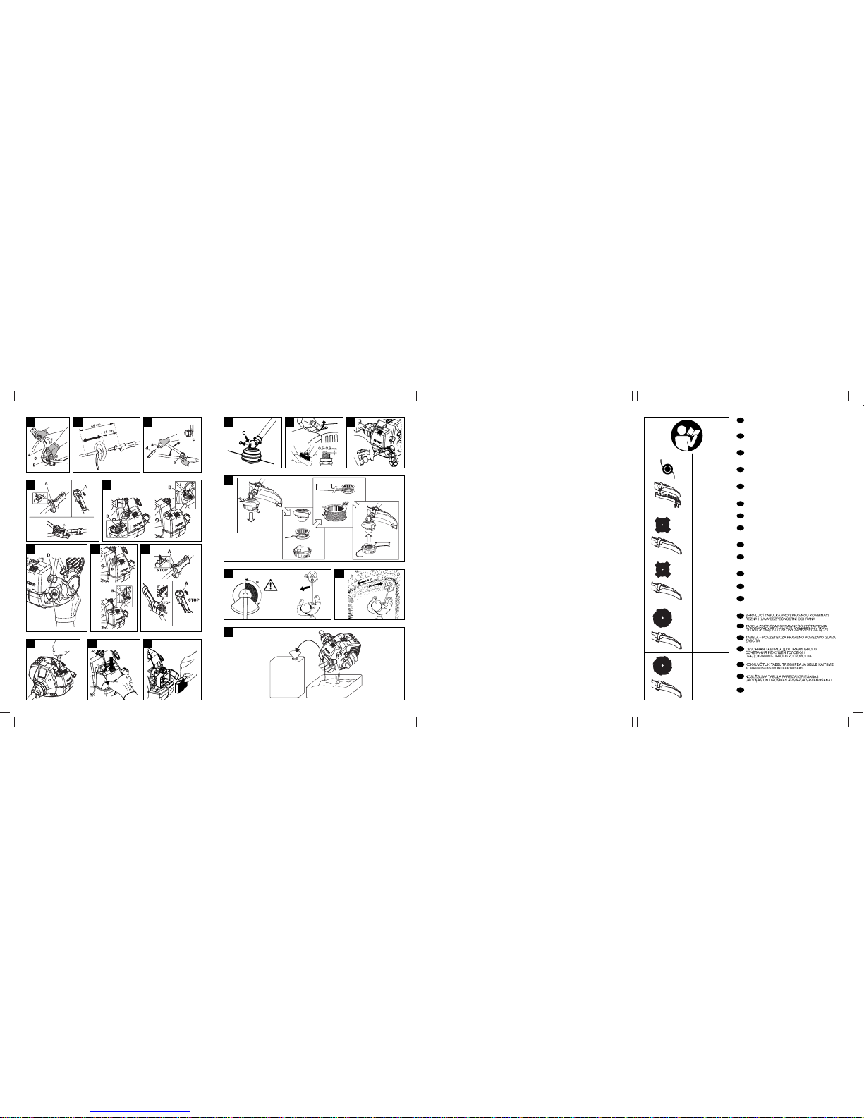
SUMMARY CHART TO IDENTIFY THE CORRECT
GUARD NEEDED, WITH DIFFERENT CUTTING
ATTACHMENTS
ÜBERSICHTSTABELLE ZUR AUSWAHL DES RICHTIGEN SCHUTZBLECHES FÜR DIE EINZELNEN
SCHNEIDWERKZEUGE
TABLEAU RECAPITULATIF POUR LE CORRECT
ACCOUPLEMENT LAME OU TETE FIL NYLON /
DEFENSE DE SECURITE
OVERZICHTSTABEL OM TE BEPALEN WELKE
BESCHERMKAP GEBRUIKT MOET WORDEN BIJ DE
DIVERSE MAAI-ONDERDELEN
TABELL FOR KORREKT MONTERING AV TRÅDSPOLE/SAGBLAD OG SPRUTSKJÆRM/SIKKERHETSVÆRN
TAULOKKO LEIKKAAVAN PÄÄN/TURVASUOJUKSEN
OIKEASTA YHDISTELMÄSTÄ
SAMMANFATTANDE TABELL ÖVER KORREKT KOMBINATION AV SKÄRHUVUD/SÄKERHETSSKYDD
OVERSIGTSTABEL VEDRØRENDE DEN KORREKTE
SAMMENSÆTNING AF KNIV OG
BESKYTTELSESSKÆRM
TABLA PARA EL CORRECTO ACOPLAMIENTO DE LA
CABEZA CORTANTE Y PROTECTOR DE SEGURIDAD
TABELA DE RESUMO PARA A CORRETA
APLICAÇÃO DA CABEÇA CORTANTE E DEFESA DE
SEGURANÇA
TABELLA RIASSUNTIVA PER IL CORRETTO ABBINAMENTO TESTA TAGLIENTE / DIFESA DI SICUREZZA
ÖSSZEFOGLALÓ TÁBLÁZAT: A NYÍRÓFEJ
ÖSSZEÁLLITÁSA / BALESETVÉDELEM
ΠEPIΛHΠTIKOΣ ΠINAKAΣ ΓIA THN EΠIΣHMANΣH
TOY KATAΛΛHΛOY ΠPOΦYΛAKTHPA,ME ∆IAΦOPA
KOΠTIKA EΞAPTHMATA
DO⁄RU B‹R G‹Y‹M fiEKL‹ ‹Ç‹N ÖZETLEY‹C‹
TABELA KES‹C‹ KAFA / EMN‹YET KORUNMASI
GB
DE
FR
NL
NO
FI
SE
DK
ES
PT
IT
HU
GR
CZ
PL
SK
RU
EE
LV
TR
Page 4
ENGLISH - 1
Warning
Safety apparel: Approved protective
goggles or visor, approved hard hat
and hearing protection.
Read the instructions for the user
carefully and make sure you understand how all the controls work.
Safety apparel: Approved gloves.
Safety apparel: Approved boots.
Do not smoke when refueling or
using the machine.
Explanation of Symbols
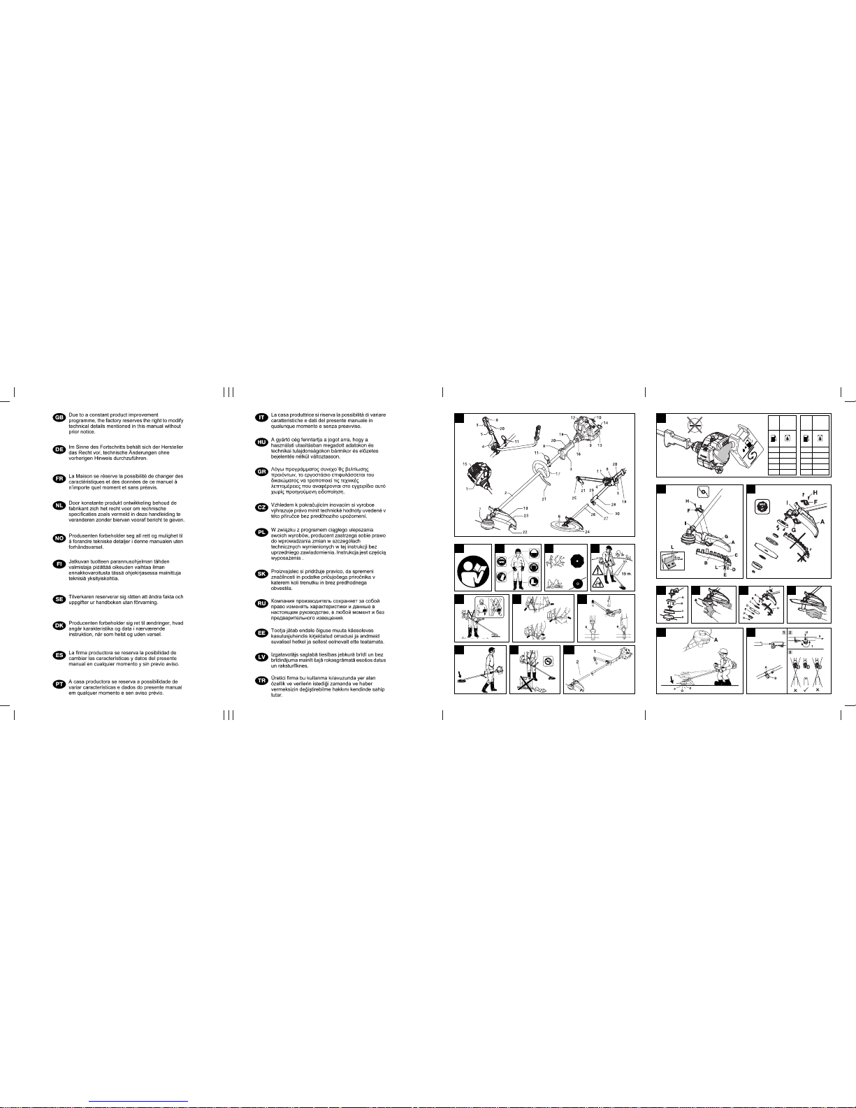
A. General description
1) ENGINE
2) SHAFT
3) THROTTLE TRIGGER
4) GRIP ADJUSTMENT KNOB
5) RIGHT CONTROL HANDLE
6) BLADE
7) NYLON STRING HEAD
8) STOP SWITCH
9) FUEL ENRICHMENT LEVER
10) STARTER HANDLE
11) HARNESS RING
12) SPARK PLUG
13) AIR FILTER COVER
14) FUEL TANK CAP
15) MUFFLER SHIELD
16) ENGINE/SHAFT JOINT
17) DELTA HANDLE
18) REAR CONTROL GRIP
19) SAFETY GUARD
20) SAFETY LEVER
21) SAFETY POLE GUARD
22) STRING CUTTER BLADE
23) NYLON STRING HEAD GUARD EXTENSION
24) BLADE GUARD
25) FRONT HANDLE
26) ATTACHMENT
27) LOCKING PIN
28) SHAFT / ATTACHMENT JOINT
29) LOCKING PIN HOUSINGS
30) JOINT KNOB
B. Safety precautions
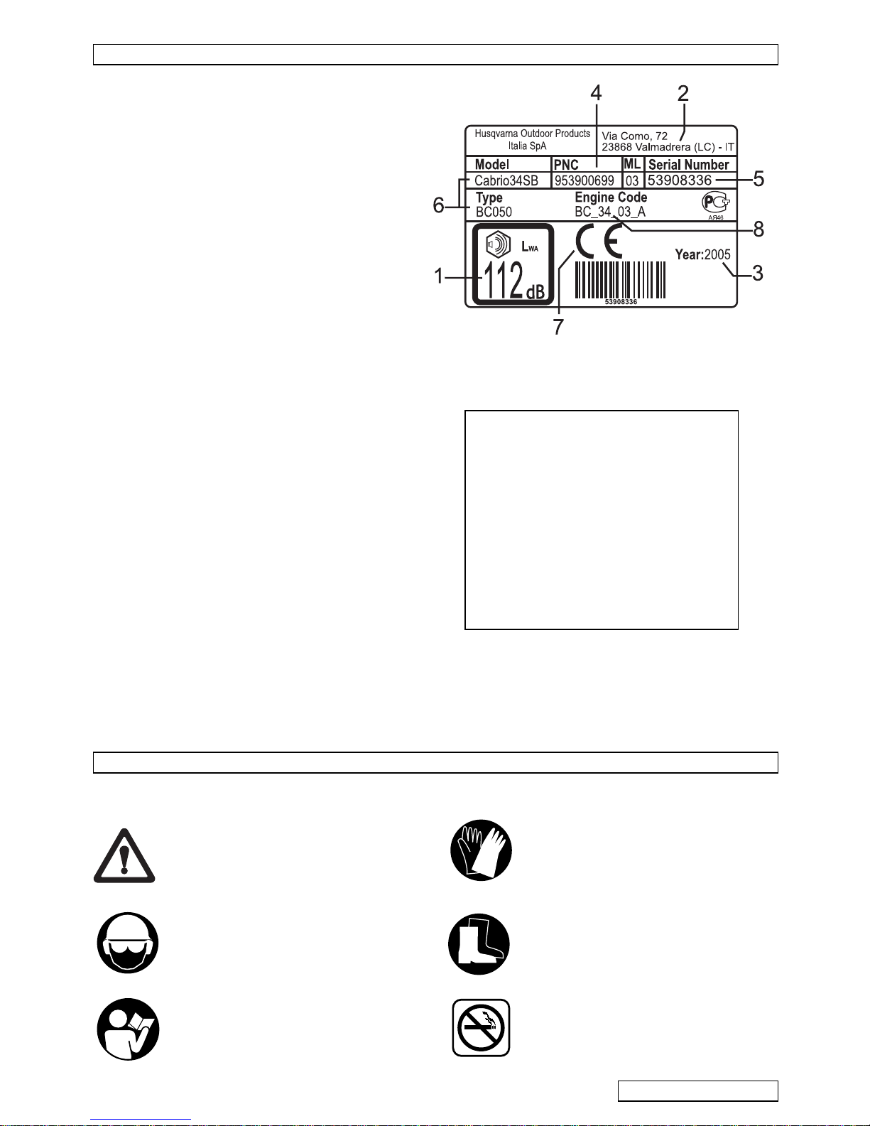
LEGEND:
1) Guaranteed noise level according to
directive 2000/14/EC
2) Manufacturer's name and address
3) Year of manufacture
4) Product code
5) Serial no.
6) Model/type
7) CE marking of conformity
8)
Displacement
Example of identification label
Page 5
2-ENGLISH
Prior to use
• Do not use this machine for any other purpose than that
for which it was designed, using the proper cutting
devices as indicated in the instructions.
•
B1.
Anyone who uses the machine should have r ead
the entire ma nu al wi th ex treme care.
• Make sure yo u kn ow how to s to p the engi ne and bl ade
if necessary (see section entitled “Starting an d stopping
the engine”).
• All use rs should be familiar with the op er ations for us e
of the machine under absolutely safe conditions as
described in this manual, and should be instructed in
the proper cutting techniques to use, possibly by
practic al demonstration.
• Do not use the machine if you are tired, in poor health
or under the effects of alcohol or medication that could
affect you r reac ti ons.
• Do not allow children or persons who are not familiar
with these instructions and are not sufficiently trained to
use the brush cutter. Local regulations may specify an
age limit for users.
• Keep this manual with the machine when selling or
lending it, to enable the future users to familiarize
themselves with the product and instr uctions for sa fe
use.
• Always inspect the machine carefully prior to use: make
sure it is correctly assembled and that there are no
loose screws, damaged parts, fuel leaks.
• Replace any accessories (blades, nylon string heads,
guards) which show damage or cracks or appear
excessively w orn. Have your Autho rized Service
Center replace any damag ed parts.
• Perform all operations of maintenance and/or assembly
ONLY with the engine off and wearing gl oves.
Apparel
•
B2.
Dress suitably for the job; wear approved personal
protection gear: a) Close-fitting clothing (no shorts or
loose clothes). b) Safety boots with non-slip sole,
crush-res ist an t toe c ap an d prot ec tion agai nst c uts (d o
not wear sa ndals or work bar efoot). c) Sturdy gloves
resistant to cuts and vibrations. d) Safety visor or
protective goggles. Remove the protective film if any. e)
Hearing p rotection . The use of p ersonal pr otection ge ar
does not eliminate the risk of injury but may reduce the
effect of the damage in case of accidents.
• Do not wear loose clothing or jewelry that could get
caught in the moving parts of the machine.
• Watch out fo r the rota ting part s a nd ho t surf aces of th e
machine.
Health p r ecaution s
• Prolonged use of the machine or other equipment
expose the operator to vibr ations that ca n cause the
White Finger Syndrome (Syn dr o m e of Ray n aud). This
could reduce the sensitivity of the hands i n
distingu ishing differ ent temperatures and cause a
general numbness. The op erator should therefore
check the co nditions of the hands and fingers if the
machine is used continuously or regularly. If one of the
symptoms should appear, consult a doctor
immediately.
• Prolonged use of the machine or other equipment can
cause disco m fort, stress, fatigue, hearing damage.
Wear suitable hearing pr otection whe n using the
machine. Cor rect and scrupul ous maintenance can
also help to protect you further from the risk of noise
and vibration.
• Never start or run the engin e in a closed or poorly
ventilated place.
Work zone
• Exam ine t he wo rk area and be care fu l of an y hazards
(such as ro ads, driveways, power lines, hanging tree
limbs, etc.).
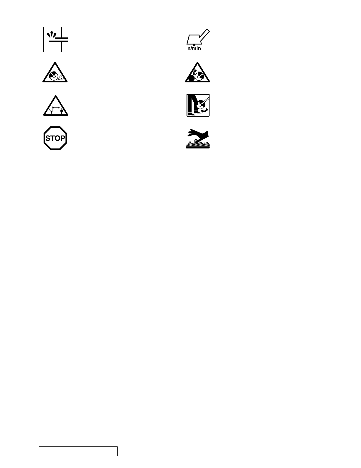
Fuel enrichment (starting aid).
Danger of f lying debris.
Minimum safety distance 15m.
Emergency stop.
15 m
Maximum shaft speed.
Danger of kickback. The blade is capable
of amputating arms and legs.
CAUTION!
Danger of serious leg injur ies. Take
scrupulous care to follow the instructions
in the manual.
CAUTION!
The cutting parts and muff ler may get
very hot and ca us e bu r ns. Wa it a few
minutes before touching them.
CAUTION!
Avoid prolonged use. Noise and
vibrations may be dangerous.
CAUTION!
The exhaust fumes are toxic if
inhaled, and may cause asphixiation and even
death.
Page 6

ENGLISH - 3
• Before use, remove any rubbish from the work area
such as rocks, broken glass, ropes, metal parts, cans,
bottles and any foreign body that could become
entangled with rotating parts or be projected
dangerously at a distance. Contact between the blades
and any extraneous objects could cause serious injury
to the operator or other people or animals in the vicinity,
and could also damage the machine.
•
B3.
Cut only the material recommended for each
accessory and take care not to let the blades come into
contact with rocks, metal parts, etc.
• Take special care when working on sloping terrain.
•
B4.
Keep any other persons or animals away from the
work zone (minimum distance 15 meters). Since there
is a danger when you are working that the blade or
nylon str ing head could throw out grass, dirt, roc ks or
foreign bodies, when someone approaches switch the
engine off or stop the blade or rotating head (see
section entitled “Starting and stoppi ng the engine”).
• Take account of possible hazards that may not be
perceived because of the noise of the machine.
• Make sure there is someone in the vicinity within safe
calling distance in case of accident.
During use
•
B5.
Fasten your ha ir above shoulder length .
• B6. Use the machine holding it to the right of your body
so that the exhaust fumes can escape freely withou t
obstruction from your clothing. If you have never used
a brush cutter before, practice using it for a while before
actually starting to work with it
•
B6.
While working, grip the brush cutter firmly with both
hands. Stand in a stable position on your feet.
• Keep the gr ips clean and dry.
• Before starting to work, make sure you are wearing the
harness cor rectly. Adjust th e buckle so that the brush
cutter is well balanced on your right side with the blade
or nylon string head parallel to the ground, from 0 to 30
cm above it.
•
B7.
harness ring (B) should be kept in the original
position so as not to unbalance the machine.
• Never try to use the mach ine with any of its parts
missing or defective, or after any alterations have been
made to it by persons other than authorized service
personnel.
• The operator or user is lia ble for any accid ents or
damages to third parties and propert y, and for the
dangers to which they ma y be exposed.
• Do not use the brush cutter while standing on a ladder
or other unstable support. You should always be able
to control your balance.
• Do not use the machine under extreme weather
conditi ons such as very low temperat ures or in a very
hot, damp climate.
• Avoid working in bad weather (fog, rain, wind, etc.).
• The blade is sharp, so be very careful when handling it
even with the e ngin e off. We ar wo rk glo ves. S wit ch the
engine off and wait for all rotating parts to come to a
complete stop before pe r fo r m in g an y operation on the
machine or touching th e blade or nylon string head,
especial ly if you ha ve to remov e any materi al entang led
with those parts.
• Keep all parts of your body and clothing away from the
blades during startup or when the engine is runn ing.
• During use, keep the work zo ne in front of you. Never
cut walking backwards as you cannot see possible
hazards.
• Do not put the machine down wi th the engine running.
Never leave the machine alone.
• Never leave the machine with the engine running.
Precautions for carrying the machine
•
B8.
Never carry the brush cutter, even for short
distance s, with the engi ne running. S witch off the
engine and carry it with the blade or nylon string head
facing backward.
•
B8.
When you transport the br ush cutter in a motor
vehicle, place it in a stable fixed position so that no fuel
leaks out. We recommend em ptying the fuel tank
whenever you transport the machine.
Fire prevention pre cauti ons
•
B9.
Never work with the brush cutter in the presence of
fire or spilled gasoline.
•
B9.
When filling the fuel tank, dry any spilled fuel. Do
not smoke during this operation. Start the engine at a
distance from the filling site and far away from any fuel
tanks (at least 3 meters). Do not fill the tank with the
engine running.
• Keep the ma chine clean by removing any gras s
cuttings, le av es , ex c es s oil to red uc e the fire haz ar d.
Precaut ions for o pe ratin g a split sh aft ma ch in e
•
B10.
If your machine is a split shaft model, that is to say
compose d of a power un it (
1
) and an attachment (2),
you must fur thermore conform to the following rules:
Never turn on the machine without an attachment
correctly fitted. Before every start check the
attachment/shaft joint and the attachment to be
assembled correcty and in excellent cond itions.
This manual is meant to be: the manual of the power
unit; th e m anual of the string head/grass blade
attachment and, moreo v er, if not expl icitly stated
otherways, it refers to the two unit s as already
assembled in ther proper way (see chapter F6.
attachments fitting/removal)
When using other attachments, carefully read their
instruction manual and make sure you understand
them before using . This machines allows the fitting of
the following attachments only: UNIVERSAL
OUTDOOR ACCESSORIES - Hedge Cutter
Attachment.
CAUTION!
In order to ensure proper operation
and safe use of the machin e, make sure to use
original replacements at all times.
CAUTION!
For your safety, du rin g tra ns por t an d
storage, always protect the blade with the guard
supplied with the machine.
Page 7

4-ENGLISH
Kickback
Machines equipped wit h blades may produce a violent
kickback on contact with solid bodies. T he blade is
capable of amputating arms and legs. The force of the
kickback can cause the operator to lose control of the
machine.
Kickback can also occur when cutting with any type of
blade in the ha zardous zo ne (see
N1
); we therefore
recommend cutting using the remaining zone.
This section describes the safety devices on the
machine, and provides instructions for control and
maintenance to keep them in perfect working order. The
section “General Description” will help you to identify the
parts described in this section. The risk of accidents
increases considerably if maintenance is not perform ed
regularly or is not done professionally. In case of any
doubts contact an authorized service center.
Safety lever
• This d evice serves to prev ent acc identa lly pr essi ng the
throttle trigger (f ig.
A
no. 3). In fact, the tri gger (fig. A no.
3
), can only be pressed if the safety lever is pressed at
the same time (fig.
A
no. 20).
• By mean s of 2 se pa rate springs , up on re le as in g the
grip, the throttle trigger (fig.
A
no. 3) and safety lever
(fig.
A
no. 20) return automatically to their original
positions.
Engine stop device
• Turn the st op bu tto n Stop (fig. A no. 8) to O / STOP to
stop the engine.
• To make sure this button works properly, start the
engine and check that it stops when the Stop button
(fig.
A
no. 8) is turned to the Stop position.
Protection for transport
The guard covers the sharp extremities of the blade when
the machine is in the resting position for transport or
storage (fig.
A
no. 24).
Safety guard
• This very important safety device (fig. A no.19)
prevents any objects that come into contact with the
cutting device, or the grass itself, fr om flying up and
striking the operator. It should be checked regularly;
check the assembly and make sure the fasteni ng
screws are tight (see “Assembly of safety guard”).
• If you strike any hard objects t hat cause structural
damage to the guard on the cutting device, take the
machine to an authorized service center for
replacement of the guard.
Safety pole guard
This device, fastened to t he machine, ensures a
minimum distance between t he operator and the cutting
device during use, and prevents the ma chine from
striking and injuring the operator if the blade hits a hard
surface (f ig.
A
no. 21).
Muffler
• The muffler serves to reduce the noise level to a
minimum and to route the exhaust fumes produced by
the combustion engine away from the operator.
• Follow these procedures for safe use of the brush
cutter.
CAUTION!
Always use a sharp blade. A blade
with worn teeth can create problems in cutting
and cause t he blade to kickback.
CAUTION!
Do not sharpen a damaged or worn
blade. Replace it with a new one.
CAUTION!
We recommend the use of or iginal
accessories and replacements, which can be
purchased from authorized distributors. The use
of other accessories and replacements increases
the danger of accidents and in this case the
manufacturer has no liability for damages to
persons and/or property.
C. Description of the safety devices on the machine,
controls to be made and maintenance of the safety devices
CAUTION!
Do not use the machine for any
reason wit h its saf ety devices out of or d er.
CAUTION!
Never use the m achine with its Safety
lever pressed with adhesive tape, string or other.
CAUTION!
Before a pplying the gu ard switch of f
the engine and wait for the cutting device to stop.
Use the blade guard whenever you have t o
transpor t and store the machine.
CAUTION!
Never use the machine for any reason
without the specific safety devices listed below!
Though they do not entirely eliminate all risks,
they greatly reduce the danger.
CAUTION!
Never use the machine for any reason
withou t the recommen ded safety gu ard for the
cutting device in use. The use of an inadequate or
defective guard can cause serious injuries.
Periodically, check its conditions and replace if
necessary.
CAUTION!
Never use a brush cutter without its
safety pole guard correctly in place.
CAUTION!
The muffler ca n ge t ve ry ho t during
use and should be allowed to cool for some time
after swi tching off the engine. Therefore, take
special pr ecautions wh en, for any reason, you
have to touch the area around the muffler.
CAUTION!
Fire hazard. Never use the machine
with a de fective or damaged muffler.
Page 8

ENGLISH - 5
Harness
The harne ss is equipped with a fasten-release
mechanis m. The har ness enab les the oper ator to sup port
the machine during use (see “Safety precautions”,
B7
).
Before fast enin g the ma chi ne to the stra ppin g, a djus t the
bandolier belt so that the fasten/release device is about
15 cm above your waist. Using the blade, fasten the
machine to the buckle using the hole nearest your body.
Preparation of the m ixture
• To obta in the best mixture, pour the oil into an app roved
containe r first , fol lowe d by th e gas olin e, and shak e the
container well (every time you take fuel out of it).
• Be careful not to spill the gasoline.
• The characteristics of the mixture tend to deteriorate in
time, so you should only prepare as much mixture as
you are going to need (the use of deteriorated fuel can
seriously damage the engi ne).
Filling the tan k
• Fill the tank in a well-ventilated place.
• Place the machine on a solid flat surface so that it
cannot tip over, with the cap on the tank facing upward.
• Clean the area around the fuel cap before removing it,
to prevent any impuriti es from contaminating the fuel.
• Take the cap off the fuel container careful ly. Unscrew
the cap on the fuel tank and fill it with the necessary
quality, using a funnel.
• Take care not to spill any fuel.
• After filling the tank, screw the cap on tightly.
• During use, to prevent problems in starting the engine
again, we st rongly recommend that you avoid letting
the fuel run out in the tank.
Fuel storage
• Gasolin e is highly inf lammable.
• Before going near an y ty pe of fuel , put out your
cigarette, pipe or cigar.
• Store the fuel in a cool, well-ventilated place, in an
approved fuel storage container.
• Never store the engine with fuel in the tank in a poorly
ventilated place where the fumes pro duced by the
CAUTION!
Engine exhaust fumes are toxic. For
this reason, you should not use the machine
indoors.
CAUTION!
Engine exhaust fumes can get very
hot and may contain sparks. Do not use the
machine near inflammab le material.
CAUTION!
It is very important to fami liarize
yourself with the release mechanism. In case of
emergency you need to be able to release the
machine quickly.
D. Fuel Mixture
CAUTION!
• Do not smoke while refueling!
• Open the c ap on th e tank by looseni ng it slo wly.
• Fill the tank outdoor, far from flames or sparks.
• Never add fuel in the tank when the engine is
running or hot to avoid the risk of fire (let the
engine cool off before filling the tank).
• Avoid contact of the oil and fuel with the skin
and eyes.
• Fill the tank in a well-ventilated place.
• Do not inhale the toxic fumes of the fuel
mixture.
• Store th e fuel mixture i n suitab le fuel c ontainer s
only.
CAUTION!
Do not use any other type of fuel than
the type recommende d in this manual. This
machine is equipped with a two-stroke engine
and should therefore be fueled with a mixture of
unleaded gasoline (with a minimum octane rating
= 90) and fully synthetic oil specific for two-speed
engines th at us e un leaded gasol i n e in the
proportion s indicate d in the table on the cover, fi g.
(
D
).
CAUTION!
Control the specifications of the oil
shown on the pac k ag e; the use of oil lack ing the
specifications expressly indicated in this manual
could caus e ser i ou s damage to the engine!
CAUTION!
The following precautions should be
taken to reduce the fire hazard:
• Always ensure there is adeq uate ventilation.
• Do not smoke or take sources of heat or sparks
near the fuel.
• Refuel with the engine off.
• Open the cap on the tank carefully to eliminate
any excess pre ssure.
• Do not take the cap off the tank with the engine
running.
• After fu eling, close the cap tightly.
CAUTION!
If you spill any fuel, wipe it off the
machine. If you have spilt it on yourself, change
your clothes at once. Avoid contact with t he skin
or eyes.
CAUTION!
The muffler gets very hot during use
and remain s hot for so me tim e a fte r s witching off
the engine . Thi s also applies at idle sp ee d. Take
every precaution to reduce the fire haz ard,
especially in the pres ence of inflammable
materi al s or ga s.
Page 9

6-ENGLISH
gasoline could propagate and reach a fire, candle,
burner or furnace pilot light, water heater, dryer, etc.
• The fumes produced by the fuel can cause an
explosion or fire.
• Never store excessive quantit ies of fuel.
E1,E2. Assembly o f safety g uard
Fit the sa fety guard (A) against the gearbox (I) position
the lower cl am p (
G
) in the housing under the s hield and
the upper clamp (
F
) over the s haft . Inse rt an d tigh ten th e
screws (
H
).
E1. Safety guard extension (exclusively for use with
nylon string hea d)
• The exte nsio n (B) should be install ed on ly for use w ith
the nylon s tr ing head, with the aid of the str ing cutter
blade (
L
), that reg ulates the length of the string and
thus the cutting diameter.
• For correct assembly see the illustration on the cover
and perform the following sequence of st eps:
• Insert the ex tension (
B
) on the safety guard (A) at the
reference notches (
C
), and fasten with the screws (D),
then apply the string cutter blade (
L
) with the cutting
edge facing towards the outside of the shield, and
fasten it with the screw (
E
) (Make sure the screws are
tightened all the way (
E
) and are not loosened by the
vibrations. If necessary, tighten them again).
Assembly of nylon string head and bl ade
Apply the proper guard depending on whether you plan to
use the grass blade or nylon string head (see chapter:
“Application of protect iv e de vices on cutter ”).
•
F1.
Apply the nylon string head as shown in the
illustrat ion: a) Protec tion flange b) U pper plate c) Gua rd
d) Nylon string head. Tighten by turning
counterclockwise.
•
F2.
As you tighten, hold the nylon string head and plate
still and in sert the wren ch or screwdri ver suppli ed in the
holes in the plate and gearbox; first turn the plate until
the two holes match.
•
F3.
Apply the bl ade as shown in the illustra tion: a)
Protection flange b) Upper plate with blade centering c)
Guard d) Blade with wording and direction arrow facing
upward e) L ower plate f) Fixed cup g) Blade fastening
nut.
•
F4.
Make sur e the hole in the blade i s perfectly coupled
with the cen terin g coll ar on the up per pl ate. Ti gh ten by
turning counterclockw ise. As you tighten, hold the
blade-plate assembly s till by inserting the wrench or
screwdriver supp lie d in the ho les provid ed .
F5. “Tap and go” nylon string head
The nylon string head is used to cut grass and weeds
along borders or in zones with obstacles like walls, fences
or trees. It can operate in a very narrow or uneven zone.
The nylon string cuts the grass neatly without damaging
the bark of t he trees or causing violent impact such as
due to the contact of a rigid blade with a hard surface.
F6. attachments fitting/rem o val (for split shaft
models only)
1) Loosen the joint knob first, then insert at tachment’s
shaft into the shaft/attachment joint (1) and make
sure that th e locking pin(A) is secured in one of its
housings, finally lock firml y the joint knob(B).
2) To remove the attachment from the power unit:
loosen the joint knob(1), push the locking pin (2) and,
keeping it pr e s se d , rem ov e at tac h m en t ’s shaft from
the joint(3).
3) Every attachment manual explains through a picture
in which ways each attac hm e nt can be assemb le d
on the powe r unit: a configuration is forbidden if
crossed ,if marked with “NO” and/or the symbol,
E. Assembly of safety guard
CAUTION!
If you are using the grass cutting
blade, rem ove the ex tensio n (B) on the guard (A).
F. Usable cutting tools and their installation on the machine
CAUTION!
The follo wing are the only cutting
devices t hat can be installed on your machine:
a) Nylon string head
b) Grass blade with a maximum of 8 teeth.
Each of these devices requires the installation of
a special gu ard. Follow th e instruc tions for corr ect
assembly carefully. Fasten the cutting tools
correctly with al l th eir pa rts in the order i nd icated
so as to prevent severe injuries to the operators,
other people and anima ls.
CAUTION!
Use grass blades or nylon string
heads with the MAXIMUM ROTATION SPEED
(stencile d on them by the m an ufa c t ur er ) of at
least 10.500 min
-1
.
CAUTION!
Any opera tions involving the cutting
devices and their guards should be done with the
engine off.
CAUTION!
If you turn the machine over to
facilitate assembly of the cutting tools, make sure
the cap on the fuel tank is securely fastened and
there are no leaks of fuel.
CAUTION!
WE RECOMMEND THE USE OF
ORIGINAL ACCESSORIES AND
REPLACEMENTS, WHICH CAN BE
PURCHASED FROM AUTHORIZED
DISTRIBUTORS. THE USE OF OTHER
ACCESSORIES AND REPLACEMENTS
INCREASES THE DANGER OF ACCIDENTS
AND IN THIS CASE THE MANUFACTURER
HAS NO LIABILITY FOR DAMAGES TO
PERSONS AND/OR PROPERTY.
F3. CAUTION!
Do not use the nylon string head
guard extension (H) with metal blades.
Page 10

CAUTION! First read chapter “Safety
Precautions”
CAUTION! Start the brush cutter in a flat
place. During startup stand in a stable position. Make sure the blade or nylon string head do
not touch the ground or any obstacles.
CAUTION! Grip the knob of the starter with
one hand and hold the machine in a stable
position with the other. (Take care not to wind the
starter string around your hand) and pull slowly
until you encounter some resistance, then pull the
cord sharply and forcefully (to start the engine
when cold or warm follow the procedures
described).
CAUTION! Do not pull the starter cord all
the way and do not release it abruptly
against the machine as this could damage it.
Startup of cold engine
• H1. Stop switch (A) turned to I opposite the
“STOP” mark.
• H2. Turn the fuel enrichment lever (B) to the
closed position.
• H3. Pump by pressing several times on the
bulb (C) until you see the fuel flow back into the
tank through the tube (D). Pull the starter cord
until the machine starts.
Let the engine run a few seconds holding the
brush cutter still. Grasp the control grip firmly and
accelerate, automatically the enrichment lever will
return to its original position.
CAUTION! The cutting devices are now
rotating.
Startup of warm engine
• H1. STOP switch turned to I (START). Throttle
trigger lever in minimum position (released).
• H4. Enrichment lever (B) in original position.
H. Starting and stopping the engine
ENGLISH - 7
G1. Double handled grip
The grip (A) can be adjusted to suit the needs of
the operator by moving it forward or backward.
Loosen the knob (C), place the handle in the
desired position then tighten the knob (C) again.
CAUTION! The handle assembly (A) can be
folded parallel to the transmission shaft to
facilitate transport and storage of the machine.
Loosen the knob (C), turn the support (B), by 90°
clockwise, fold the handle (A) in the desired position and tighten the knob (C).
G2. Delta handle
For your safety, fasten the delta handle in front of the
label placed on the shaft at a distance of at least 18
cm from the rear grip. The handle should be fastened in a comfortable working position. The safety
pole guard should be mounted using the accessories supplied and in the configuration shown in the
figure, in contact with the delta handle.
Bent front grip
CAUTION! The grip acts as a guard when
the special extension is mounted (D). Screw
the side safety guard securely into the threaded
housing on the bent grip as shown in the figure,
whenever you use the cutting blade.
The bent grip (A) can be adjusted according to
the needs of the operator by folding it forward or
backward. Press the grip adjustment knob (B),
place the grip in one of the positions marked with
the notches (C) in a convenient working position
and release the knob (B).
CAUTION! With the blade installed, use the
machine with the grip adjusted in the posi-
tion marked with the first notch only.
CAUTION! Fold the grip parallel to the
machine - in the position of the last notch (C)
- to facilitate transport and storage of the machine.
G. Assembly of grips
or if it isn’t shown at all. A configuration is allowed
if marked with “OK” and/or the symbol. The
figure shows assembling configurations allowed
for the string head/grass blade attachment (with
the rules defined in the previous paragraph, it is
forbidden to assemble the string head/grass
blade attachment with the locking pin in both left
and right housings, allowing its assembling in the
upper housing only).
Supply of the nylon string
CAUTION! The string cutting blade housed
in the plastic shield will cut the nylon string
to optimum length; a string that is too long
reduces the rotation speed of the engine and
interferes with cutting efficiency, as well as
increasing the risk of injury.
During cutting, the nylon string wears naturally
causing an increase in the speed of the engine
and a reduced cutting capacity. When this happens, to bring out more string bump the head
against the ground: release the throttle trigger to
reduce the engine speed to less than 4000 rpm.
Tap gently on the ground with the button (A)
as shown in the figure and the string will come
out automatically. Accelerate again. If the string
does not come out make sure there is still some
left and try again.
Page 11

8 - ENGLISH
• H3. Pump by pressing several times on the
bulb (C) until you see the fuel flow back into the
tank through the tube (D). Pull the starter cord.
Stopping the engine
• H5. Turn the stop switch (A) to O (STOP).
CAUTION! After stopping the engine the
rotating parts, blade or nylon string head,
keep spinning by inertia for a few seconds. Grip
the machine firmly until they stop.
CAUTION! In case of emergency the above
delay can be abbreviated by scraping the
blade supporting cup parallel on the ground.
Your machine can be equipped with a low emission carburetor. We recommend that you have
any adjustment of the carburetor made exclusively by an authorized service center, which disposes
of special equipment for ensuring the best performance with the lowest emissions. To adjust the
speed to the minimum, turn the screw marked (T)
as shown: With the engine running and well
warmed up, turn the screw (T) gently clockwise,
until the engine rotates at regular speed (stead
noise), without the cutting devices in motion. If
the cutting devices are moving, turn the screw (T)
gently counterclockwise until you obtain the proper adjustment. The correct minimum speed is
shown in the instruction manual in the paragraph
of technical data.
CAUTION! All the above adjustments
should be made with the cutting devices
correctly installed.
CAUTION! Start the brush cutter in a flat
place. During startup stand in a stable
position. Make sure the blade or nylon string
head do not touch the ground or any obstacles.
The warranty may be invalidated due to erroneous adjustments made by personnel not
belonging toauthorized service centers.
I. Carburetor adjustment
Check periodically to see that all the screws in the
machine are securely fastened in place. Replace
damaged, worn, cracked or bent blades. Always
make sure the blade or nylon string head is correctly installed and the nut holding the blade is tight.
L1. Cleaning the air filter
(At least every 25 hours of work). A clogged filter
causes alteration of the carburetor adjustment,
reducing power and increasing fuel consumption,
as well as causing difficulties in startup. Open the
cover on the filter as shown in the figure by pressing in the point indicated by the arrow for release.
Clean the inside of the filter housing thoroughly
(fig. L2). The filter can be cleaned using gentle
jets of compressed air. For more thorough cleaning it can be washed in soapy water.
L3. Gearbox
Every 50 working hours add grease for high
speed gears in the gearbox, through the hole (C).
L4. Spark plug
Periodically (at least every 50 hours) remove and
clean the spark plug and set the space between
the electrodes (0.5/0.6 mm). Replace it if excessively encrusted or, in any case, after 100 working
hours. In case of excessive encrustation check
the carburetor adjustment, the percentage of oil in
the fuel mixture and make sure the oil is of excellent quality and suitable for two-stroke engines.
L5. Fuel filter
To clean or replace the filter, remove the cap on the
tank and take the filter out using a hook or longnose pliers. Periodically, every season, contact your
service center for general maintenance and cleaning of the inside. This will reduce the possibility of
unexpected problems and will ensure the good
performance and long life of your machine.
CAUTION! Regularly it is important, in order
to prevent the engine from overheating, to
remove the dust and dirt from the vents, the cylinder cover and fins on the cylinder, using a wooden scraper.
CAUTION! In case of prolonged disuse,
empty the fuel tank and run the engine until
it is out of gas. Store the brush cutter in a dry
place.
L6. Attachments maintenance (for split shaft
models only)
Follow maintenance instructions on the attachment manual.
L. Routine maintenance
CAUTION! Use only the recommended type
of nylon string. Do not use steel wires for any
reason, in order to prevent serious injury.
String replacement
If, when you bump the nylon string head on the
ground, no more string comes out, it means there is
none left and you have to replace it.
To replace the
M. Replacement of nylon string
Page 12

ENGLISH - 9
reel of string, press both the release pawls indicated by the arrows, remove the empty reel,
unroll any string left and rewind the new string.
Open the original package of string and insert the
ends of the two strings in the eyelets on the reel,
then wind the strings completely on the reel in the
same direction and fasten the end of each string
in the 2 opposite grooves. Replace the reel in its
housing and thread the ends of the strings in their
bushings. Pull each string so that about 15 cm
comes out on each side. Reassemble the nylon
string head as shown. If the reel becomes exces-
sively worn, replace it with a whole new reel.
Replacement of entire string reel
If the reel becomes excessively worn, replace it
with a whole new reel.
Replacement of the complete nylon string head
If upon visual inspection (and in any case after a
violent bump) the casing on the nylon string head
appears damaged, it should be replaced. For this
operation see “Usable cutting tools and their
installation on the machine”.
CAUTION! Before using the machine read
the following chapters carefully: “Safety
Precautions” and “Description of safety devices”.
CAUTION! Always wear the recommended
personal protection gear.
CAUTION! Before using the machine, make
sure all the parts are properly assembled.
CAUTION! In mounting the cutting utensils
follow the instructions in the chapter entitled “Usable cutting tools and their installation on
the machine”. ABSOLUTELY DO NOT USE THE
BRUSH CUTTER IF THE SPECIFIC SAFETY
GUARD FOR THE CUTTING DEVICE IN USE IS
NOT SECURELY FASTENED (see chapter
“Assembly of safety guards”). Failure to follow this
rule can expose you to serious danger such as:
a) possible contact with rotating and cutting parts
b) possible contact with flying debris.
CAUTION! Do not use worn or damaged
cutting devices.
CAUTION! Try to limit contact and impact
of the cutting devices against the ground
and other objects as much as possible. Hold the
cutting device away from your body.
CAUTION! Twigs or grass may jam
between the safety guard and the blade or
nylon string head. Never try to remove this material with the engine running and the blade rotating. Always stop the engine before performing
any operations of cleaning, and wait for the cutting device to stop in order to prevent injury.
CAUTION! During use and for a few min-
utes after switching off the machine, the
gearbox and zone near the shaft on which the
cutting device is fastened are very hot. Contact
can cause burns. Do not touch these parts if they
are still hot.
CAUTION! The muffler and its guard are
very hot during use and after the engine has
been switched off, even with the engine running at
minimum speed. Contact can cause burns. Do
not touch these parts if they are still hot.
The machine is ideal to complete the work of the
lawnmover. In fact, it can reach places where a
normal lawnmower is unable to go. During the
cutting operations, keep the engine running at
high speed. After every cutting stage, decelerate
the engine to minimum speed as running it at top
speed without a load can damage the engine
severely. Never raise the brush cutter above knee
level during cutting. Wait until the engine is running at minimum speed before moving the
machine from one section to another. Stop the
engine when you change workplace. Before you
start cutting again, make sure your position is
correct and stable. Cutting and trimming grass
borders with the nylon string head
CAUTION! For nylon string heads, use only
strings made of flexible material recommended by the manufacturer. For example, you
should never use metal wire because it could
cause serious injuries to people, property and animals. An unsuitable string could break and turn
into a very dangerous missile.
Cutting with the nylon string head is suitable for
light jobs like trimming borders and cutting the
grass around trees.
Mowing
To prevent damage to your lawn or the cutting
mechanism, keep the string parallel to the ground
but avoid contact with the terrain.
Trimming borders
Angle the nylon string head keeping it a short distance from the ground. Cut using the end of the
string. Do not press the string against the material
to be cut.
Drawing out the string
As you cut, the nylon string wears down naturally.
When this happens, to draw out more string bump
the head against the ground (see paragraph entitled “Tap and go system for nylon string head”).
N. Cutting techniques
Page 13

10 - ENGLISH
Thinning grass with the grass cutter blade
Cutting with the blade is recommen d ed for thinning the
grass, especially when tall and sturdy.
N2.
The grass is cut with swinging motions from side to
side, mainta ining th e blade pa rallel to the grou nd. During
the right to left sw ing the grass is cu t, while the backswing
must be made without using the blade. KICKBACK can
occur when cutting is done wi th the risk sector of the
blade; we recommend cutting with the re st of the blade.
Take care t hat the cup supporting the blade just grazes
the ground. This will prevent the blade from touching the
ground.
This section contains information useful for maintaining
the characteristics of eco- compatibility in cluded in the
origin design of the machine, and as regards proper use
and disposal of oil and f uel.
Design
In the de sign s tage, c are wa s take n to de velop an en gine
with reduced consumption and low emissions of noise
and pollutant exhaust fumes.
Use of machine
The operations of filling the tank with the fuel mixture
should be carried out in such a way as to avoid spilling
fuel and contaminating the soil and environment.
Periods of prolonged disuse
Always empty the fuel tank with the same precautions
used in filling it (
O
).
Disposal
Do not disp os e i na pp r op riately of the m ac h in e w h en it is
no longer usable. Deliver it to an authorized organization
for proper disposal in compliance with the regulations in
force.
The engine co ntinue s to hav e problem s: con ta ct yo ur auth orize d sup plier
CAUTION!
Always work with a sharp blade. A
blade with worn teeth can create problems in
cutting and can cause KICKBACK, that is, a
violent thrust on the f ront of the machine caused
by the impact of the blade against wood or solid
foreign bodies. This kickback can cause loss of
control of the machine. Never sharpen a
damaged blade: replace with a new one.
N1. CAUTION!
Do not let the blad e cut in th e risk
sector to prevent kickback (see paragraph “Safety
precautions”).
N1. CAUTION!
WE RECOMMEND THE USE OF
ORIGINAL ACCESSORIES AND
REPLACEMENTS; THESE CAN BE FOUND AT
YOUR OFFICIAL DISTRIBUTOR'S. THE USE
OF ACC ESSORIES AND REPLACEMEN TS
THAT ARE NOT ORIGINAL INCREASES THE
DANGER OF ACCIDENTS AND IN THIS CASE
THE MANUFACTURER IS NOT LIABLE FOR
ANY DAMAGES TO PERSONS OR
PROPERTY.
O. Environmental information
P. Troubleshooting table
The engi ne does n ot
start
The engine stutters
or loses power
The machine starts
but does not cut
properly
Make sure the STOP switch is on I.
●
Make sure that the fuel tank is at least 25% full.
●●
Make sure the air filter is clean.
●●
Remove t he spark plug, dr y and cl ean it, th en return
it to its place. If necessary, replace it.
●●
Change the fuel fil ter. Contact your sup pl ie r.
●
Follow the co rr ec t procedure for as se m bl y of th e
cutting accessories.
●
Make sure the m eta l ac c es so ries are shar p, an d
contact y our supplier if necessary.
●
Page 14

ENGLISH - 11
R. Technical data
Displacement (cm3) .......................................................................................................
Bore (mm) ....................................................................................................................
Stroke (mm) ..................................................................................................................
Engine output (kW) (ISO 8893) .......................................................................................
Maximum shaft rotation frequency (min
-1
) ......................................................................
Rotation speed (frequency of rotation) of engine at maximum rotation
frequency recommended for shaft (min
-1
) ......................................................................
Engine speed at max power (min
-1
) ...............................................................................
Minimum speed (min
-1
) ...................................................................................................
Maximum speed, no load (min
-1
) ....................................................................................
Dry weight (kg) .............................................................................................................
Fuel tank capacity (cm
3
) .................................................................................................
Noise pressure (at operator ear) Lp
av (dBA) (ISO 7917) ..................................................
Measured sound power level Lw
av (dBA) (ISO 10884) ...................................................
Guaranteed noise level Lw
av (dBA) (ISO 10884) .............................................................
Vibrations of rear/right grip (m/s
2
) (ISO 5349) ................................................................
Vibrations of front/left grip (m/s
2
) (ISO 5349) ..................................................................
Q. Declaration of conformity
The undersigned, authorized by Husqvarna Outdoor Products Italia SpA, declares that the following products model /TYPE: BC020, BC021, BC022 starting from the serial numbers produced from 2006 on,
manufactured by Husqvarna Outdoor Products Italia SpA, Valmadrera, Italia, comply with European
Directive: 98/37/EEC (Machine Directive), 93/68/EEC (EEC Marking Directive) & 89/336/EEC
(Electromagnetic Compatibility Directive), directive 2000/14/EEC (Enclosure V).
Valmadrera, 15.10.06
Giuseppe Todero (Technical Manager)
Husqvarna Outdoor Products Italia SpA
Via Como 72, 23868 Valmadrera (Lecco)
ITALY
30
38
26
0.8
7700
10780
8500
2800
10500
5.4
400
99
113
114
4.3-15
7-15
30
38
26
0.8
7700
10780
8500
2800
10500
5.4
400
99
113
114
2.3-14.2
5.3-12.4
30
38
26
0.8
7700
10780
8500
2800
10500
5.4
400
99
113
114
3.6-15
4.2-12
Delta grip 30cc
“Ergo” grip
Double handled grip
 Loading...