

Page 1

//1MtrEULLOtrH,
t-
OPERATION
MAINTENANCE
SAFETY
Your new string trimmer is a complex tool.
For
your
own
safety,
please
read this
manual before attempting to operate
your
new unit.
Failure to follow instructions can
result in serious
personal
injury. Spend
a
few moments
to familiarize
vourself
with
tew moments
to lamrlranze
yoursell
wrtn
your
trimmer before each
use.
USER
MANUAL
MAC@ 291
6
EAGER BEAVER@ 28,282
GAs
STB'ruG
TRIMMERS
PN
98587-04
O U.S.A. . McCulloch Corooration.
1993 Printed in U.S.A
Page 2
Dear
Customer,
Thank
you
for
purchasing
a
McCullo-ch
product'
With
proper
operation
and
mainienance
it will
provide
you
with
years of
service,
ln
order
to
make
the
best
use
of
your investment'
be
CenfAtru
to
familiarize
yourself
with
the
contents
of
the
ENTIRE
User
Manual
before
attempting
to
operate
and
maintain
Your
unit.
Be
sure
to
carefully
follow
the
step-by-step
illustrations
in
this
manual
to start,
operate
and
maintain
your new
product.
ln the
manual
there
will
be
the
following
call-outs:
NOTE'
WARNING /
CAUTION
and
WARRANTY'
A
NOTE:
is
used
to
convey
additional
information'
to
highlight
a
particular
explanation,
or
expand
a step
description.
GENERALINFORMATION.
.
. .
.
3
1-..|
....
Introduction
1-2.
. ..
AboutYourManual
1-3....
AboutYourUnit
1-4.
...
AssemblY
Requirements
1-5.
...
Specifications
GENERALIDENTIFICATION.
...4
2-1
. .
..
General
ldentification
2-2.
. ..
Sd{etY
Features
SAFEWPRECAUTIONS.
.
..
..
5
3-1....
WhatToDo
3-2.
.
..
What
NOT
To
Do
ASSEMBLYINSTRUCTIONS
...7
4-1
. .
..
Handle
AssemblY
4-2.
.
..
SparkArrester
Installation
4-3.
.
. .
DebrisShield
Installation
FUELANDLUBRICATION
. ..
..8
5-1....
Fuel
5-2.
.
..
Mixing
Fuel
5-3.
...
FuelMixingTable
5-4.
.
..
Use
Of Blended
Fuels
OPERATINGINSTRUCTIONS
...9
6-1.
.. .
StartingACold
Engine
6-2.
.
..
To
StoP
The
Engine
6-3.
..
. WarmEngine
Start
A
WARNING
"..
CAUTION
ii"n1iti""
a
procedure
which,
if
not
undertaken
or
if
improperly
done,
can
result
in
serious
personal
iniury
or
damage
to
the
unit
and/or
both'
rn"
@
(wARRANW
sYMBoL)
serves
notice
that
unless
instructions
or
procedures
are
followed'
any
J.t"gt
l"rted
will
voidthe
warranty
and
repairs
will
be
at
owner's
expense'
Service
other
than
user
maintenance
should
be
o"rtormeO
bv
a
McCulloch
Authorized
Service
Center'
b.t"g"
or
conditions
which
render
this
product
inop"iiuru
caused
by
improper
maintenance
practices
will
void
the
manufacturer's
warranty'
McCulloch
CorPoratlon
Product
Servlce
DePartme
nt
TRIMMING
INSTRUCTIONS
.
11
7-1.
. .
.
Additional
Safety
Precautions
7-2.
. .
. Stringhead
Line
Release
7-3.
. .
.
Trimming
Procedures
MAINTENANCE
INSTRUCTIONS
13
8-1.
..
.
Preventive
Maintenance
8-2.
. .
. RePlacingCutterLine
8-3.
. .
.
Removing/
Replacing
Stringhead
8-4.
...AirFilter
8-5.
.
..
FuelCaP/Fuel
Filter
8-6.
. .
.
CarburetorAdiustment
8-7....SParkPlug
8-8.
. .
.
SParkArresterScreen
8-9.
.
. .
Debris
Shield
Knife
Sharpening
8-10.
..
StoringAUnlt
8-11.
. .
Removing
A
Unit
From
Storage
ACCESSORIES
&
LUBRICANTS
.
.'''''
18
TROUBLESHOOTINGTHESTRINGHEAD
. .
19
TROUBLESHOOTINGTHE
ENGINE
. .
.
. . 20
Page 3
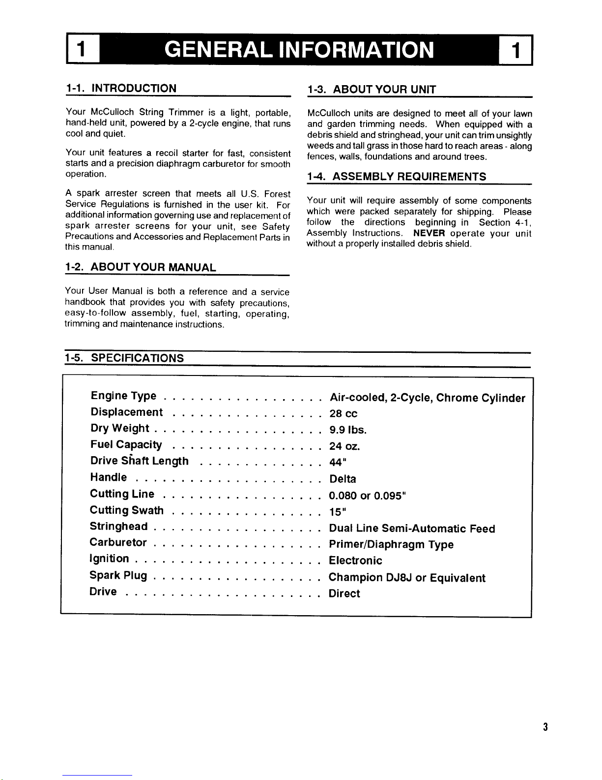
1-1. INTRODUCTION
1.3.
ABOUT YOUR UNIT
Your
McCulloch
String
Trimmer
is a light,
portable,
hand-held
unit,
powered
by
a 2-cycle
engine, that
runs
cool and
quiet.
Your
unit features
a recoil
starter for
fast, consistent
starts and a precision
diaphragm
carburetor for
smooth
operation.
A
spark
arrester
screen
that meets
all
U.S. Forest
Service
Regulations
is
furnished
in
the user kit.
For
additional
information governing
use and
replacement
of
spark
arrester
screens
for
your
unit, see
Safety
Precautions
and Accessories
and
Replacement
Parts
in
this
manual.
1-2.
ABOUTYOUR
MANUAL
McCulloch
units are designed
to meet all
of
your
lawn
and
garden
trimming
needs. When
equipped with
a
debris shield
and stringhead,
your
unit can trim
unsightly
weeds
and tall
grass
in those hard
to reach areas
-
along
fences, walls, foundations
and around
trees.
1.4. ASSEMBLY
REQUIREMENTS
Your unit
will require assembly
of some
components
which
were
packed
separately
for shipping.
Please
follow
the
directions beginning
in Section
4-1,
Assembly
Instructions.
NEVER operate
your
unit
without a
properly
installed
debris shield.
Your
User
Manual
is both
a reference
and a service
handbook
that
provides
you
with
safety
precautions,
easy-to-follow
assembly,
fuel,
starting,
operating,
trimming
and
maintenance
instructions.
1.5. SPECIFICATIONS
Engine
Type
Air-cooled
,2-Cycle,
Chrome
Cylinder
Displacement
29
cc
DryWeight...
9.9tbs.
Fuef
Capacity
24 oz.
Drive
Shaft
Length
44"
Handle
Delta
Cutting
Line
O.O8O
or 0.095"
Cutting
Swath
15u
Stringhead
. . .
Duat Line
Semi-Automatic
Feed
Carburetor
.
primer/Diaphragm
Type
lgnition
Electronic
Spark
Plug
.
Champion
DJ8J or
Equivatent
Drive
Direct
Page 4
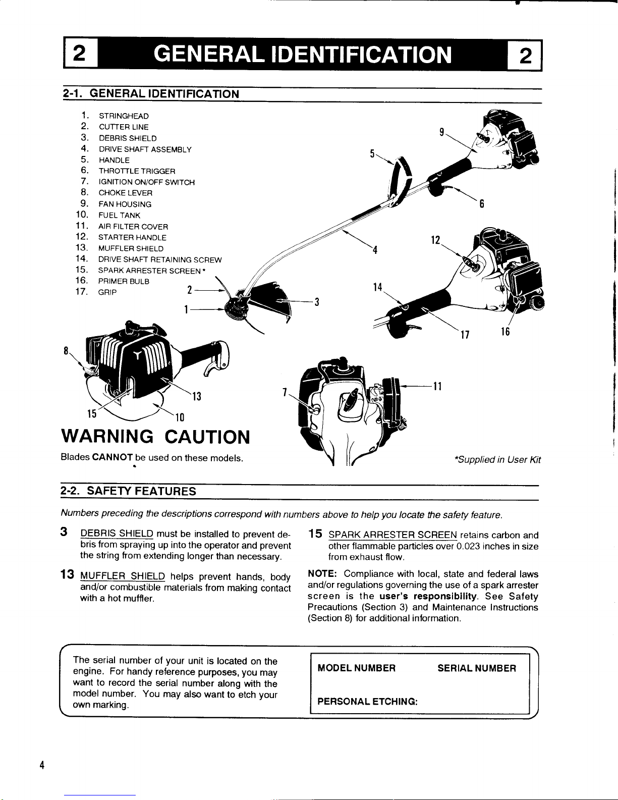
2.1. GENERAL
IDENTTFICATION
1.
STRINGHEAD
2.
CUTTER
LINE
3. DEBRIS
SHIELD
4.
DRIVE
SHAFT
ASSEMBLY
5.
HANDLE
6.
THRoTTLETRIGGER
7. IGNITIoN
oN/oFF
SWIToH
8.
cHoKE
LEVER
9. FAN
HoustNG
1
0. FUEL
TANK
11
, AIR FILTER
coVER
12,
STARTER
HANDLE
13.
MUFFLER
sHtELD
14.
DRtvE
sHAFT RETAINtNG
scREw
15.
SPARKARRESTER
SCREEN*
16.
PRIMER
BULB
17.
cRrP
\o
WARNING
CAUTION
Blades
CANNOT
be
used on
these
models.
"Supplied
in User
Kit
2-2.
SAFEW
FEATURES
Numbers preceding
the descriptions
correspond
with numbers
above to help
you
locate the safety feature.
3
DEBRIS
SHIELD
must
be
installed
to
prevent
de-
ffi|rort
spaytng
up
into
the operator
and
prevent
the string
from
extending
longer
than
necessary.
13
uurrlen
Sgtrlo
hetps
prevent
hands,
body
and/or
combustible
materials
from
making
contact
with
a hot
muffler.
15 Spnnx nnReSfER
SCneEru retains
carbon and
other flammable
particles
over 0.023 inches
in size
from exhaust
flow.
NOTE: Compliance with
local, state and federal
laws
and/or
regulations
governing
the use of a spark arrester
screen is
the user's responsibility.
See Safety
Precautions
(Section
3) and Maintenance Instructions
(Section
8) for additional information.
The
serial
number
of
your
unit
is located
on
the
engine.
For handy
reference
purposes,
you
may
want
to record
the
serial
number
along
with
the
model
number.
You
may also
want
to etch
your
own marking.
MODEL NUMBER
SERIAL
NUMBER
PERSONAL
ETCHING:
Page 5

3-1. WHAT
TO DO
READ
YOUR
USEB
MANUALAND
ALL
SUP-
PLEMENTS
(tF
ANY
ENCLOSED)
THOR_
OUGHLY
BEFORE
OPERATING
YOIJR
UNIT.
1.
WEAR
CLOSE
FITTING,
TOUGH
WORK
CLOTHING
that will
provide
protection,
such
as long
slacks
or trou_
sers,
safety
work
shoes,
heavy
duty
work
gloves,
a
safety
face
shield,
goggles
or safety
glasses
for
eye
protection
and
a
good
grade
of ear
plugs
or
other
sound
barriers
br hearing protection.
2.
REFUEL
lN
A SAFE
PLACE,
Open
fuet
cap
slowty
to
retease
any
pressure
which
may
have
formed
in fuel
tank.
To
prevent
a fire
hazard,
move
at least
10
Jeet
(3
meters)
lrom
fueling
area
before
starting.
3.
lF
FUEL
HAS
SPTLLED
ON
UNIT,
be sure
engine
has
been
dried
completely
before
starting
it.
4,
COMPLY
WITH
ALL
FIRE
PREVENTION
REGULATIONS.
We recommend
you
keep a
shoveland
fire
extinguisher
close
by
whenever
using
your
unrt
in
areas
where
dry
grass,
leaves
or
other
flammable
mate_
rials
are
present,
To
operate a gasoline-powered
prod-
uct
on
U.S.
National
Forest
Lands
or forest,
brush
or
grass-covered
lands
in
many
U.S.
states
-
including
California,
Maine,
New
Hampshire,
Oregon,
Washington
-
you
must
have
an
approved
spark
arrester
screen
properly
installed
and
maintained
on
the
engine
muffler.
The
spark
arrester
screen
must
remove
and
retain
carb_
on and
other
flammable
particles
over
0.023
inches
in
size
from
engine
exhaust
flow.
NOTE:
COMPLIANCE
WITH
ALL
LocAL,
STATE,
oR
FEDERAL
LAWS
IN THE
UNITED
STATES
IS THE
USER'S
BESPONSIBILITY.
Your
unit
comes
with
a sparK
arresrer
screen
furnishe?
in
the
user kit.
Replacement
sparK
arrester
screen
kits
are
available
at
your
nearest
McCulloch
Authorized
Service
Center
listed
under
.SAWS,
in
vour
Telephone
Directory
Yellow
pages.
lf
you
have
any
questions
concerning
spark
arrester
screens
or their
use,
wrrte
to:
McCulloch
Corporation,
product
Service
Depanment,
P.O.
Box
1 1990,
Tucson,
Arizona
85734.
Or,
vou
can
call our
toll-free
number,
USA: 1-800-423-6302.
Arizona
residents
call
1-800-221
-6507.
NOTES:
8.
9.
5. TURN
UNIT OFF
before setting
it down.
6.
ALWAYS
HOLD UNIT FIRMLY
WITH
BOTH HANDS.
the thumb and
f ngers encircling
the handles.
7. KEEPALLSCREWS
AND
FASTENERSTTGHT.
Never
operate your
equipment
when it
is improperly
adjusted
or not completely
and
securely
assembled.
KEEP HANDLES
DRY, clean
and free
of
fuel mixture.
KEEP STRINGHEAD
AS
CLOSE
TO GROUND
AS
PRACTICAL.
Avoid hitting
smail
objects
with
stringhead.
When
cutting
on a slope,
stand
below
stringhead.
NEVER
cut
or trim
on a hill
or slope,
etc.. if
there is
the slightest
chance
of slipping,
sliding
or
losing
firm footing.
10. CHECK
AREA
YOU
WILL BE
TRIMMING
FOR
DEBRIS
that
may
be struck
or thrown
during
operation.
Clear
area
before
operating
equipment.
11.
KEEP ALL
PARTS
OF YOUR
BODY
AND
CLOTHING
AWAY
FROM
STRINGHEAD
when
starting
or running
engine.
Before
starting
engine,
make
sure
stringhead
will
not come
in contact
with
any
obstacle.
12.
STOP
ENGINE before
examining
cutting
line.
13.
STORE
EOUIPMENT
AWAY
FROM
POSSIBLE
IGNITION
SOURCES,
such
as
gas-powered
water
heat-
ers,
clothes
dryers,
or oil-fired
furnaces,
portable
heat-
ers,
etc.
14. ALWAYS
KEEP
the
debris
shield,
stringhead,
ano
en-
gine
free of
debris
build-up.
15. TURN
IGNITION
SWITCH
TO
OFF
and remove
soarx
plug
boot
from
spark
plug
to
avord
any chance
of acci-
dental
starting
before
replacing
stringhead
or line.
16.
OPERATIONOFEOUTPMENT
should
atwavs
oe
re-
stricted
to
mature
and
properly
instructed
indviduals.
Page 6

3
SAFETY PRECAUTIONS
3
3.2.
WHAT
NOT TO DO
WARNING
DO NOT
OPERATETHIS EOUIPMENT
with other
peo-
ple
or animals in
the imrnediate vicinity.
ALLOW a safe
distance
of at least 30 feet
(10
meters)
between operator
and other
people
or animals.
EDGINCJSCALPING
lS NOT RECOMMENDED
w h e n
other
people
or
animals are within 100 feet.
OO NOT SWEEP
WITH UNIT. Sweeping refers
to tilting
head
attachment
to sweep away debris from
sidewalks,
driveways,
etc.
tlfh
oo NoT usE ANy
orHER FUEL than
that rec-
\llommended in
your
nnnual.
Always follow instruc-
tions
in the Fuel
and Lubrication section
of this manual.
Never
use
gasoline
unless it is
properly
mixed with
2-cycle engine lubricant.
Permanent
damage to
engine
will result, voiding
manufacturer's
warranty.
5. DO NOT
OPERATE
EQUIPMENT wearing
loose
scarves, shorts,
dangling
jewelry,
key chains,
etc., or
while
barefoot.
OO NOT SMOKE
while refueling
or operating
equip-
ment.
DO
NOT START
EOUIPMENT WHEREYOU
FUEL IT,
Move
at least
10 feet
(3
meters)
from fueling
areas
before
starting.
DO NOT
OPERATE
UNIT WITHOUT A
MUFFLER
and
properly
installed muffler
shield.
OONOTTOUCH
or let
your
hands or
body come in
contact with
a hot mlffler
or spark
plug
wire.
10.
11.
1.
DO
NOT ALLOW DIRT.
FUEL OR DEBRIS to build uo
on engrne.
DO
NOT OPERATE UNIT
lN AWK\TVARO POS|IIONS,
otf balance, outstretched
arms, or one-handed. Always
use two hands
when
operating unit
with thumbs and
fingers encircling the
handles.
DO
NOT USE STEEL LINE OR PLASTIC-COATED
STEEL
LINE. The use of steel
line
or
plastic-coated
steel
line is
extremely
dangerous. Your stringhead is
designed
to
be
used with .080 or .095" diameter nylon
line.
DO NOT RAISE STRINGHEAD
above knee level while
unit is operating.
lnjury to operator could result.
DO NOT USE
ANY TYPE BLADE OR SAW CHAIN
CUTTER
HEAD unless soecified or included.
DO NOT
USE UNIT FOR ANY PURPOSES OTHER
than trimming
or mowing weeds or
grass.
DO NOTOPERATEUNIT
FOR PROLONGED PERIOOS,
Rest
periodically.
DO NOT
OPERATE UNIT WHILE UNDER THE
INFLUENCE OF ALCOHOL
OR
DRUGS.
DO NOT OPERATE UN]T UNLESS DEBRIS SHIELD
AND/OR GUARD IS INSTALLED AND IN GOOO
CONDITION.
1fhoo
Nor ADD, REMovE oR ALTER ANY
\l/coupoNENTs
oFTHts
pRooUCT.
Doing so
could cause
personal
injury and/or damage the
unit
void ing the rnanufacturer's warranty.
12.
2.
3.
4.
13.
14.
15.
16.
17.
18.
19.
6.
7.
L
9.
CAUTION
Extremely long
hair may be
drawn into the engine by the cooling
fan.
Ensure long
hair is
protected
and kept clear of the cooling
fan intake
area.
Page 7

4.1. HANDLE
ASSEMBLY
NOTE:
The
Delta handle
is attached
to the shaft
but has
been turned
under
for ease
of
packing.
Figure
z1-1A
1 .
Loosen adjustment
knob
and rotate
handle
to top
of
shaft.
(Figure
4-1A)
2. Retighten
adjustment
knob
securely.
4.2.
SPARK
ARRESTER
INSTALLATION
NOTE:
Spark
Arrester
is required
when
using your
trimmeron
U.S. National
Forest
Lands. Checkvourlocal
state
requirements.
1 .
Place
your
unit on
a work bench
or level
surface
with
the muffler
facing you
as shown
in Figure
4-2A.
2.
Access
to the
screen
area can
be made
through
the
opening
on
the back
of
the muffler
shield.
lt is
not
necessafo
to
remove
the
muffler
shield to
install
the
screen.
REMOVE
SCREW
Figure
4'2A
3.
Using
a screwdriver,
remove
the
screen
cover
taining
screw.
(Figure
4-2A)
INSTALL
IN ORDER
SHOWN
>
:-@SCREEN
\K-
\
-COVER
\
Figure
rl-2B
-
scREw
4. Install
the spark arrester
screen,
the screen
cover
and scure in
place
with the retaining
screw.
(Figure
4-28)
NOTE:
A dirty spark
arrester screen
can dramatically
reduce
performance.
4.3. DEBRIS
SHIELD
INSTALLATION
WARNING
The debris
shield must
be installed
to
properly
dispense
cutter
line and
protect
operator.
@ ""Qg
Figure
zL3A
Figure
4-38
6-112"
To
8-112'
Figure
4-3C
Page 8

5.1. FUEL
Engine fuel is a mixture of
gasoline
and 2-cycle oil. The
correct ratio
of
gasoline
to oil is very important.
Follow
the ratios in the Fuel Mixing Table.
Use regular
grade
unleaded
gasoline
mixed with
McCulloch 40:1
custom 2-cycle engine oil for best
results. Use mixino
ratios in Section 5-3.
CAUTION
@
Never use
straight
gasoline
in
your
unit. Never use a fuel
mixture that has been stored for over
90 days.
This will
cause
permanent
engine damage
and
void the
manufacturer's warranty for
that
product.
CAUTION
@
lf 2-cycle
lubricant other than McCulloch Custom
Lubricant
is to be used, it must be
a
premium
grade
2-cycle oil mixed
at a
40:1 ratio. lf
insufficient lubrication
is
the cause of engine
damage, it voids the
manufacturer's
warranty for that
product.
5-2.
MIXING FUEL
Mix fuel in
a container equipped with
a flexible spout and
strainer.
See the Fuel Mixing Table for the
correct ratio
of
gasoline
to oil. Pour half of
the
gasoline
and all of the
oil
into the container.
Cover the container and shake
vigorously.
Add the rest
of
the
gasoline
and again shake
container to
thoroughly mix fuel and
oil.
GAUTTON
@
Never attempt
to mix
the
gasoline
and lubricating
oil in
the
fuel
tank
of the
unit.
Special starting
fluids
SHOULD NOT
be used because
seals
and other
rubber composition
parts
may be
damaged.
5.3. FUEL
MIXING
TABLE
GASOLINE
McCulloch
40:1 Ratio Custom Lubricant
1/2 U.S.
Gal.
1 U.S. Gal.
2.5 US
Gal.
5 U.>.
(:at.
1.6 oz.
3,2 oz.
8.0
oz.
16.0 oz.
48 ml
(cc)
95 ml
(cc)
237 ml
(cc)
475
ml
(cc)
1 Liter
5 Liters
20 Liters
0.9 oz,
4.3 oz.
17.O oz.
25 ml
(cc)
125 ml
(cc)
500 ml
(cc)
1 lmp. Gal.
2lmp.
Gal,
5lmp. Gal.
4.3 oz.
8.6
oz.
21 .4 oz.
125 ml
(cc)
250
ml
(cc)
52s ml
(cc)
Mixing
Procedute:
40 Part3 Gasoline to 1
Part Lubricant
1ml
=lcc
Ihe use of a fuel additive
such as STA-BILo Gas Stabilizer
or
an equivalent will
mrnimize the fornntion of
fuel
gum
deposits.
Such an additive
should only be used
when the
fuel/oil
mix rs
prepared.
Add 1 1 ml I 0.4 oz.
per gallon
of
gasoline
or mix
per
instructrons on container.
NEVER add
fuel
additives directly to
the unit fuel tank.
5.4. USE
OF BLENDED
FUELS
Today's fuels
are often a blend
of
gasoline
and one or more oxygenates such
as ethanol, methanol,
MTBE
(ether)
and axonal. These
blends are often referred to as
gasohol, premium
or super unleaded.
We recommend
regular unleaded
gasoline
for
use in
your
McCulloch
product.
However, if
you
choose to use a
blended
fuel or its use is unavoidable,
the following
precautions
are recommended.
1.
Always use fresh fuel mixed
peryou
r
User Manual.
Use the special additive ALCOHOL
PROTECiOR'o
1by
cold Eagle) or
equivalent
to inhibit conosion and
reduce
oiltfuel separation
(mix
as
directed).
Always agitate
the fuel mix before
fueling unit.
Defuel
tank and run engine dry be-
fore
stonng the unit.
PROBLEMS COMMON TO
BLENDED FUELS
Some
oroblems
associated with use of
blended
fuels
include:
.
Vaoor lock
.
Poor warm restart
.
Poor
performance
at high altitudes
.
Corrosron of fuel svstem
corDonentS
GASOHOL USE MAY REQUIRE
CARBURETOR ADJUSTMENTS
Your McOulloch engine
is lubricated by
oil mixed
with
the
fuel. Using
oxygenated fuels
may alter the airlfuel
ratio causing a lean
mix
(lessfuel,
more
atr).
lf this
condition is not corrected by
adjusting the
carburetor, engine
darnage due to
poor
lubrication rnay
result.
Your McCulloch Authorized
Service
Center can make these
adjustments.
a.
Page 9

NOTE:
lgnition
is always
"ON"
6-1.
STARTING
A COLD
ENGINE
NOTE:
To minimize
load
on engine
during
starting
and
warm-up,
trim
excess
cutter
line
to 5
inches.
(Figure
6-1A)
Your
unit
is designed
with a
3
position
choke;
"CHOKE"
,
'START'.
and
"RUN".
Figure
6-18
TO
START
ENGINE
1
. Move
choke
lever
to "CHOKE" position.
(Figure
6-18)
Figure
6-1C
2. Prime
the
carburetor.
times.
(Figure
6-1C)
Figure
6-1D
3.
Squeeze
the trigger
to the
FULL THROTTLE
position.
(Figure
6-1
D)
Figure
6-1E
4. Pull
starter rope
out a
short
way until
resistance
is
lelt
(approx.
4 inches).
Pull
starter
rope
briskly
4
times.
A smooth rapid
pull
is required
for
a strong
spark.
(Figure
6-1E)
NOTE:
Throttle
must
remain
in
fullthrottle position
until
engine
starts
and
warms
up
(approx.
1
0 seconds).
5.
Move
choke
lever
to "START"
position.
pull
starter
rope
again
4 tirnes
while
holding
trigger
at
the full
throttle position.
(Figure
6-1F)
6.
lf engine
fails
to start,
repeat
steps
1
through
5.
PRIMER
t
-{
Pump
the
primer
bulb
10
Page 10

a
6 OPERATI
NG I NSTRUCTIONS
6
6-2. TO STOP
THE
ENGINE
NormalStopping:
Flgure
61G
7. Onceengineslarts,leavethechokeinthe"START"
position
for 10 seconds, then move
choke to "RUN"
position.
(Figure-6-1
G)
NOTE:
Your unit is equipped
with a throttle advance
which also can be
used during starting.
(Figure
6-1H)
NOTE: lf engine fails
to start, after repeated
attempts,
refer to Troubleshooting
section.
NOTE:
Always
pull
starter
rope straight up. Pulling
starter at
an angle will cause rope
to
rub
against the
eyelet.
This friction will cause rope to
fray and wear
quickly.
Always
hold starter handle when
rope retracts.
Never let
rope snap back from
extended
position.
This
could
cause rope to snag or fray
and also damage
the
starter assembly.
Figure 6-2A
1.
Release throttle
trigger. Let engine
return to idle.
Extend
stader rope 4"-6"
to absorb strain on starter
components
when engine stops.
Push
and
hold
ignition stop
switch until engine stops.
Allow starter
rope to
retract slowly.
(Figure
6-2A)
6.3,
WARM ENGINE
START
Flgure 6-3A
1. Place choke
in
"START"
position.
(Figure
6-3A)
2. Grasp throttle
handle firmly, squeeze throttle trigger
to FULL
throttle
position.
3.
Pull
starter
rope briskly until engine
starts, but
no
more
than 6 times. Keep throttle
at FULL
position
until
engine runs smoothly.
4.
lf engine
doesn't start,
place
choke
in
"RUN" posi-
tion and
pull
starter
rope 5 more times. lf engine
still
does not start
it is
probably
flooded.
Wait
5 minutes
and repeat
procedure
with choke in
"RUN"
position
and throttle fullopen.
t0
Page 11

7-1.
ADDITIONAL
SAFEW
PRECAUTIONS
Before
operating
your
unit, review
ALL SAFETY
PRE)AUT\oNS
in this manual.
WARNING
CAUTION
lF
UNFAMILIAR
WITHTRIMMING/CUTTING
tech-
niques,
practice
the
procedures
with ENGINE
in
'OFF'position.
ALWAYS
CLEAR
WORK
area
of debris
such as
cans,
bottles,
rocks,
etc. Striking
objects
can cause
serious
injury
to operator
or bystanders
and
also damage
equipment.
lf an
object is accidentally
hit, immediately
TURN
ENGINE
OFF
and examine
equipment.
lf
stringhead
is
cracked or
broken,
or
plastic
debris
shield
is
damaged,
replace
those
parts
immediately.
Never operate
unit with damaged
or defective
equip-
ment.
ALWAYS
HOLD
UNIT FIRMLY
with
both
hands.
thumbs
and
fingers
encircling
handles.
ALWAYS
WEAR
PROPER
CLOTHING,
work
shoes,
work
gloves,
safety
goggles
and ear
protection
to
guard
against
hearing
impairment,
ALWAYS
TRIM
OR CUT AT
HIGH
ENGINE
SPEEDS.
Do
not run
engine
slowly at
start
or during
trimming
operations.
DO NOT use equipment for
purposes
other than
trimming
or
mowing weeds.
NEVER
raise stringhead above knee height
during
operation.
DO NOT operate unit with other
people
or animals in
the immediate vicinity. Allow
a minimum of 30 feet
between operator and other
people
and animalswhen
trimming or mowing. Allow a distance
of 100 feet
between
operator and other
people
and
animalswhen
EDGING or SCALPING with
stringhead.
NEVER
OPERATE EQUIPMENT
if taking medication
that
produces
drowsiness or reduces reflexes.
NEVER OPERATE EQUIPMENT
while
drinking alco-
holic beverages
or while under the influence
of alcohol
or drugs.
lF OPERATING
UNIT ON A SLOPE,
stand below
the
cutting attachment.
DO NOT OPERATE
on a
siope
or hilly incline
if there is the slightest
chance of slipping
or losing
your
footing.
7-2.
STRINGHEAD
LINE
RELEASE
CAUTION
Periodically
remove weed
wrap to
prevent
overheating
the
drive
shaft. Weed wrap
occurs when
strands
of weeds
become entangled
around
the shaft beneath
the debris
shield
(Figure
7-28). Remove
weed wrap
with a screwdriver
or
similar device,
or refer to Section
8-3, Removing
/
Replac-
ing Stringhead.
Figure
7-2A
NOTE:
The
bump-and-feed
stringhead
allows for
quick
and
easy
line feeding
without the
need to stop
engine to
advance
line.
(Figure
7-2A)
WARNING
CAUTION
DO NOT
use steel
wire or
plastic-coated
steelwire.
To
release
fresh
line, run
engine at full
throttle and
"bump"
stringhead
against
lawn.
Line will automatically
Fiqure
7-28
release.
The
knife in
debris shield
will trim excess line.
' 'Y-'-
11
Page 12

7
TRIMMING
INSTRUCTIONS
7
7.3.
TRIMMING PROCEDURES
When
properly
equipped with a debris shield and
stringhead,
your
unit will
trim
unsightly weeds and tall
grass
in those hard-to-reach
areas
-
along fences, walls,
foundations and
around trees. lt can also be used
for
edging
along walkways
and driveways.
And it can be
used for
scalping to remove vegetation down to the
ground
for easier
preparation
of a
garden
or to clean out
a
particular
area.
WARNING
Do not use steel wire or
plastic-coated
steel wire of any
kind with
your
stringhead. Serious operator injury can
result.
NOTE:
Even with care, trimming around foundations,
brick or stone walls,
curves, etc., will result in above
normal string wear. To release
fresh line, see
instructions in Section 7-2,
Stringhead Line Release.
TRIMMING/MOWING
Swing trimmer
with a
sickle-like motion from
side to side. Do not tilt
the stringhead during
the
procedure.
Test
area to be trimmed for
proper
cutting height
Keep stringhead at
same level for even
depth of cut.
CLOSEB TBIMMING
Position trimmer straight ahead with a slight tilt so bottom
of stringhead
is above
ground
and string contact occurs
at
proper
cutting
point.
Always cut away from operator.
Do not
pull
trimmer in toward operator.
FE N C E,tr OU N DATI ON TR IM MI N G
Approach
trimming around chain link fences,
picket
fences, rock walls and foundations slowly to cut close
without whipping string against
the
barrier. lf the string
comes in contact with rock,
brick walls, or foundations, it
will break or fray.
lf
string
snags fencing, it will snap off .
TRIMMING AROUND
TREES
Trim around
tree trunks with a slow approach so string
does not contact
the tree bark. Walk around the tree
trimming
from left to right. Approach
grass
orweedswith
tip of string and tilt stringhead slightly forward.
WARNING
Use extreme
caution
when EDGING
or
SCALPING.
Keep
a distance
of
100 feet
between
operator,
other
people
and animals
during these
operations.
EDGING
Tilt unit to
the left
so that
stringhead
is
in a vertical
position.
This will allow
the nylon line
to sklm
along
the edge
of the
concrete.
Before
edging,
you
may
want to
adjust
the handle
so as
to make
this operation
as
effortless
as
possible.
Always
keep a distance
of
100 feet
from other
people
and
animals
when edging. Do
not attempt this
procedure
if there
is any chance
flying debris
could injure
operator,
other
people
or cause
damage to
property.
SCALPING
Scalping
refers lo
removal
of all
vegetation down
to the
ground.
To do
this, tilt
the stringhead
to about
a
30 degree
angle to
the
left. By adjusting
the
handle
you
will
have better
control
during
this operation.
Always keep
a
distance of
100 feet
from other
people
and
animals
when
scalping.
Do not attempt
this
procedure
if there is any
chance
flying debris
could injure
operator, other
people
or cause
damage
to
property.
WARNING
DO NOT
SWEEP
WITH TRIMMER
Sweeping
refers to tilting
stringhead to sweep
away
debris
from walkways,
etc. Your
trimmer is a
powerful
tool and
small stones
or other such
debris may
be
hurled
50 feet
or more,
causing injury
or damage to nearby
property
such
as automobiles,
homes and
windows.
12
Page 13

8.1.
PREVENTIVE
MAINTENANCE
Service
other
than routine
user
maintenance
items
should
be
performed
by
your
McCulloch
Authorized
Service
Center listed
in under
"SAWS"
in the Yellow
Pages
of
your
telephone
directory.
Keep
your
unit
clean.
Do not allow
filters, mufffer
and
cylinder
fins to become
plugged
or
covered with
dirt or
debris.
fi[
Never use
dirty fuel
or dirty
oil. Engine
damage
\lf
could result.
Always
follow
instructions
in the
Fuel
and
Lubrication
section
of this manual.
A
good preventive
maintenance
program
will
prolong
the
life and maintain the
performance
of
your
McOulloch unit.
After
the first 7 days or 15 hours of operation,
whichever
comes
eadiest, take
your
unit to
your
McOulloch
Author-
ized Service Center for
an inspection and
check-up.
Your
dealer will be
pleased
to
help
you
set up a
preven-
tive maintenance
program
to suit
your
needs.
The rec-
ommended first 7-day or 1S-hour
check-ups
and a
follow-up
of regular
periodic
check-ups
and tune-ups
will
assure long, satisfactory
service from
your
McCulloch
product.
This service will
be
performed
at
your
McCul-
loch Authorized
Service Center at existing
service rates.
MAINTENANCE
CHECKLIST
NOTE:
The
maintenance
checklist
below
is a
guide
for
preventive
maintenance.
Cleaning, adjustment,
and
parts
replacement
may,
under
certain
conditions,
be required
at more
frequent intervals than
those indicated.
MAINTENANCE
CHECK
LIST
5
H
o
U
R
S
20
H
o
U
R
S
lil
r
I
ITEM
ACTION
SCREWS
/
NUTS
/BOLTS
INSPECT
/
TIGHTEN
CONTROLS
INSPECT
TFEPLACE
AS FEQUIFED
AIR FILTER
CLEAN
OR REPLACE
FUEL FILTEB
REPLACE
DEBRIS
SHIELD
INSPECT
REPLACEAS
REQUIRED
STRINGHEAD
INSPECT
REPLACEAS
REQUIRED
SPARK PLUG
CLEAN/ADJUST/FEPLACE
MUFFLER
TCLEAN
LAMINATION
GAP
*CLEANTADJUST
EXHAUST
PORTS
*CLEAN
a
SPARKARFESTER
SCBEEN
INSPECT
REPLACE
CYLINDEB
FINS
TCLEAN
CARBUFETOR
.CLEAN
STARTER
ROPE
INSPECT
a
*REPLACE
AS REOUIRED
DRIVE
SHAFT
TLUBRICATE
(Every
50
Hours)
a
FUEL
HOSES
INSPECT
a
*REPLACEAS
REOUIRED
tFlecommended
for Maintenance
by a McCulloch
Authorized
Service Center Technician
13
Page 14

8 MAI
NTENANCE
I NSTRUCTIONS
I
8.2. REPI.ACING CUTTER LINE
Figure 8-2A
1. Turn the knob COUNTERCLOCKWISE
and remove
it. lf required use string head wrench.
2. Remove the spooland spring.
3. Remove
any remaining cutter line.
(Figure
8-2A)
Figure
8-2D
6.
Lock each
end
into a slot on opposite
sides
of the
spool.
Install
the spring
over the
spindle. Insert
each end
of the
line through an
eyelet in the housing
and lower
the spool
into the
housing while feeding
the
line through
the eyelets. Ensure
the spring seats
itself into
the spool.
(Figure
8-2D)
HAND
TIGHT
ONLY
DO
NOT
USE
WRENCH
Figure
8-2E
7. Once the
spool
is in
place,
apply
pressure
on the
spool compressing
the spring. Pull
each end of the
line sharply to
unlock them
from the slots. Continue
to apply
pressure
to the spool
until the knob can be
threaded
CLOCIQVISE
onto the
spindle. Tighten
the
knob securely
by hand
only. DO NOT USE THE
STRINGHEAD
WRENCH
TO T]GHTEN.
(Figure
8-2E)
NOTE:
Apply
an anti-seize
compound
(Permatex@
'133A
Anti-seize
or equivalent) to
the threads to make the
knob
easier lo
remove next time
service
is
required.
Flgure
8-2F
8.
Trim the
excess
line to approximately
5
inches.
This
will minimize
load on engine
during starling and
warm-up.
(Figure 8-2F)
4. Double a 18ft. length of .095
(or
.OB0) cufter line.
Thread each end through
one of the two sets of holes
on the top of the spool. Pull both ends
evenly
through the holes.
(Figure
B-28)
Figure 8-2C
5. Wind both ends around
the
spool
together
in
a
CLOCKWISE
direction to within 6" of the ends. DO
NOT
TWIST UNE ON SPOOL. Twisting line
could
cause stringhead to feed improperly.
(Figure
8-2C)
14
Page 15

8-3.
REMOVING / REPI-ACING
STRINGHEAD
I MAI NTENANCE
I NSTRUCTIONS
8
Figure &3A
1. Turn the knob
COUNTERCLOCKWISE
to remove.
Use the stringhead
wrench if required.
2. Remove the spool
and spring from
the housing.
3. Remove the
housing. Gently
tap back of housing
to
loosen. (Figure
8-3A)
_?
o*
Figure
8-48
2.
Lift filter from Air
Box.
(Figure
8-4B)
3. Wash filter in soap
and water. DO NOT USE
GASOLINEI
4.
Air dry filter.
5. Reinstall filter
in
reverse
order of removal.
NOTE: Replace f lter if frayed,
torn,
damaged or
unable to clean.
8.5. FUEL CAP/FUEL FILTER
CAUTION
Remove fuel from unit and store in approved container
before starting this
procedure.
FUEL.AP
\ t--<
htu
Figure 8-5A
NOTE: Keep vent on fuel cap clean of debris.
(Figure
B-5A)
1. Liftfuel line outoftank. Steelwirewith hookorpaper
clip works well.
(Figure
8-5B)
HAND
TlGHT
ONLY
OO NOT
USE
STRINGHEAO
WRENCH
Figure 8-3B
4. Remove
the replacement
stringhead
from the
pack-
age
intact. Place
it on the spindle.
Ensure the
hex
on
the spindle is
well seated
into the housing.
5. Compress
the'spool into
the housing
and thread
the
knob
into the assembly.
Tighten
the knob
CLOCK-
WISE,
BY HAND
ONLY.
(Figure
8-38)
84. AIR FILTER
To Clean Air Filter:
AIR
FILTER
AIR FILTER
COVER
COVER SCREWS
Figure 8-4A
1 . Remove
2 screws holding
airfilter cover
remove
cover.
(Figure
8-4A)
15
FUEt
FILTER
in
place
and
Page 16

8
MAI
NTENANCE
I NSTRUCTIONS
I
Figure &5C
2.
Pull
off with a twisting motion.
(Figure
8-5C)
3. Replace fuelfilter.
NOTE:
Neveroperate the trimmerwithoutthe
filter. Internal engine damage could result !
CARBURETOR ADJUSTMENT
The carburetor was
pre-set
at the factory for optimum
performance.
lf further adjustments are necessary,
please
take
your
unit to the nearest McOulloch Author-
ized Service Center listed in the Yellow Pages.
8-7. SPARK PLUG
CENTER
ELECTRODE
SIDE
ELECTRODE
Figure
8-7B
4. Adjust
gap
to
.025 in. Bend
side electrode
only using
a
gapping
tool.
(Figure
8-78)
5.
Reinstall
spark
plug
and torque
to 105 to
130 inch
pounds.
Reconnect
spark
plug
boot.
8€.
SPARK
ARRESTER
SCREEN
NOTE:
lt is
not necessary
to take muffler
shield off to
replace
or install
a new spark
arrester
screen.
@
8-6.
fuel
SPARK PLUG
BOOT
Figure 8-7A
1 . Remove spark
plug
boot with a twist and
pull
motion.
(Figure
8-7A)
2. Remove the spark
plug.
3. Clean spark
plug
electrodes with
emery
cloth.
REMOVE
SCREW
Figure
8-8A
SCREEN
Flgure &88
1 ,
To replace spark
arrester
screen, remove
the retain-
ing screw
and screen
cover. Discard
old
screen.
Install
new screen.
(Figure
8-8A
& 8-88)
16
Page 17

8
MAI
NTENANCE
I NSTRUCTIONS
I
8.9.
DEBRIS
SHIELD
KNIFE
SHARPENING
1 . Remove
cutter
knife from
debris
shield.
2. Place
knife
in a bench
vise.
Sharpen
knife using
a
flat file,
being
careful
to maintain
the angle
of cutting
edge.
File in one
direction
only.
Figure 8-10A
B. Pour
1 teaspoon of
clean 2-cycle
oil into
the com-
bustion
chamber. Pull
starter
rope slowly
several
times
to coat internal
components.
Replace
spark
plug.
(Figure
8-10A)
9.
Store unit in a
cool, dry
place
away
from any
source
of ignition
such as an oil
burner, water
heater,
etc.
8.1 1.
REMOVING
A UNIT FROM
STORAGE
Figure
8-9A
3.
Reinstall
knife.
Tighten
fasteners
securely.
(Figure
B-9A)
8.10.
STORING
A UNIT
Clean
and
gap
spark
plug
or install
a new spark
plug
with
proper
gap.
Prepare
unit for operation.
Fillfueltank
with
proper
fuel/ oil
mixture.
See Fuel
and
Lubrication
Section.
1.
Remove spark
plug.
2. Pull starter
rope briskly
to
clear excess
oil
from
combustion
chamber.
3.
fi[Failure
to
follow
these
steps
may cause
varnish
to
\l/form
in
the carburetor,
difficult
starting
or
perma-
nent
damage
after
storage.
1. Perform
all thd
general
maintenance
recommended
in
the Maintenance
Section
of
your
User
Manual.
2. Clean
exterior
of engine,
drive
shaft
assembly,
de-
bris
shield
and stringhead.
3.
Drain
fuelfrom
the
fueltank.
4.
After fuel
is drained,
start
engine.
5.
Run engine
at idle
until unit
stops.
This
will
purge
the
carburetor
of fuel.
6. Allow
engine
to
cool
(approximately
5 minutes),
7.
Using
a spark
plug
wrench,
remove
the spark
plug.
4.
5.
l7
Page 18

FOR PERFOBMANCE AND SAFETY REASOA'S
USE ONLY
GENUINE
McCULLOCH ACCESSORIES AND
BEPIACEMENT
PABTS.
DESCRIPTION
ACCESSORIES and REPLACEMENT PARTS
PART
NUMBER
Dual
Une Stringhead Assembly . .
Dual Line-on-Spool
Bump Knob
300160
3001s9
300339
3003s6
21904341
300323
22397541
224040
21698s
Bump Spring
Spark
Plug DJSJ
Air Filter
Debris
Shield
Spark Arrester
Screen
Fuel Filter
LUBRICANTS
3.2 oz. ONE
SHOT 22325141
224477
98463
8 oz.
(for
2.5
gal.
mix)
16 oz.
(with
easy
mix chamber)
18
Page 19

PROBLEM
PROBABLE
CAUSE
Line won't
feed.
Line
is
tangled
inside
stringhead.
Remove
spool
from
unit;
disassemble.
Untangle
line
and
wind correctly
in
direction
indicated
on spool
(see
Section
8).
Upon
removing
spool,
line
appears
to be melted
together.
Trim off
damaged
line
and rewind
line (see
Section
B).
Line
wound
in
wrong
direction
inside
stringhead.
Remove
spool.
Check
to be
certain
line is
wound
in
direction
indicated
on
line
element.
(see
Section
8)
Insufficient
line
inside
stringhead.
Remove
spool
and
install
new
line
(see
Section
B).
Internal
damage
to
stringhead
caused
by
bumping
head
too
hard
on
ground
while
advancing
line.
Disassemble
stringhead
and
examine
parts
for
damage.
Replace
parts
or entire
head
(See
Section
8).
Line
snaps
off
or frays.
lmproper
trimming procedures,
or
poor
quality
line.
See General
Trimming
Instructions
or replace
line (see
S6ction
B).
Unable
to
remove
stringhead
knob.
Stringhead
and
shaft
are
hot
to the
touch.
Stringhead
knob
over
tightened
-
use
stringhead
wrench
supplied in
user
kit.
U
s e
anf,i- se
ize
com
pou
nd
(Permatexw
133A
Anti-sdize
or
equivalent)
and
reinstall
knob
HAND
TIGHT
ONLY.
Weed
wrap.
Remove
weed
wrap
(see
Section
7).
l9
Page 20

PROBLEM
PROBABLE
CAUSE
CORRECTIVE
ACTION
Unit
won't
start
or starts
but
will
not
run.
I
ncorrect
starti
ng
Procedures
Follow
instructions
in
the User
Manual
(See
Section
6).
lncorrect
carburetor
mixture
adjustment
setting
Have
carburetor
adiusted
bY
an
Authorized
Service
Center.
Fouled
spark
plug
Remove,
clean
and
gaP (or rePlace)
spark
plug.
lf
plug is
wet, reinstall
plug
and
hold at
full
throttle
until
unit
starts.
lf
plug
is dry,
try
starting
with
choke
on
(See
Section
8).
Fuelfilter
plugged
Replace
fuelfilter
(See Section
B)'
Unit
starts,
but engine
has
low
power.
Incorrect
lever
position
on
choke
Move
to
RUN
position.
Dirty
spark
arrestor
screen
Replace
spark
arrester
screen.
Dirty
air
filter
Remove,
clean
and
reinstall
filter.
lncorrect
carburetor
mixture
adjustment
setting
Have
carburetor
adiusted
bY
Authorized
Service
Center.
an
Engine
hesitates
lncorrect
carburetor
mixture
adjustment
setting
Have
carburetor
adjusted
bY an
Authorized
Service
Center.
No
power
under
load
Runs erratically
Incorrectly
gapped
spark
Plug
Clean
/
gap
or replace
Plug.
Smokes
excessivelY
lncorrect
carburetor
mixture
adjustment
setting
Have
carburetor
adiusted
bY
Authorized
Service
Center.
an
lncorrect
fuel
mixture
Use
properly
mixed
fuel
(40:1
mixture)
.
FOR
WARRANW
OR
SERVICE
CONTACT
THE
NEAREST
MCCULLOCH
AUTHORIZED
SERVICE
CENTER
LISTED
UNDER
''SAWS'
IN
YOUR
TELEPHONE
DIRECTORY
YELLOW
PAGES.
IF
FURTHER
ASSISTANCE
IS
REQUIRED
CALL
THIS
TOLL-FREE
HOT
LINE'
PLEASE
REFERENCE
YOUR
MODEL
AND
SERIAL
NUMBER'
1€00423-6302
ln
Arizona:
1-800-221-6s07
M-F
6:00
AM
-
4:45
PM
(MST)
Page 21

/u
REFER
TO YOUR USER MANI.JAL
FOR MORE
DETAILED
INSTRUCTIONS
A. DEBRIS SHIELD
Loosen
xnoo
"no
:;" handte to the top
grip
and tighten knob.
J
.
HA.I.IDLE
Adfust
to a comfortable
distance
from
the rear
Loosen
the
screws slightly and rotate
the handle to the top a comfortable distance
from
the
rear
grip.
Tighten the screws.
BEFORE STARTING ENGINE:
Fuel
used
in this machine must
be
mixed with
McCulloch Custom Lubricant at 40:1 mix ratio
(3.2
oz.
oil to 1
gallon gasoline).
ASSEMBLY
QUICK
REFERENCE
FOLLOW THESE SIMPLE STEPS
TO ASSEMBLE
YOUR
TRIMMER
INSERT
EOLT
ACTUAL
SIZE
Locate
bolt
and
nut.
DELTA
HANDLE
Set
debris shield in
place.
Install
bolt and nut,
then
tighten
B.
c.
O U S A - McCulloch Concoration
Pnnted
rn USA
21
1373
Page 22

ltt.
CONSULTE
EN EL
MANUAL
DEL
USUARIO
SI
DESEA
INSTRUCCIONES
EN MAS
DETALLE
PROTECTORA
CONTRA ESCOMBROS
l1
1l
@"k2
Localice el
perno
y
la tuerca.
Coloque la
protectora
contra
escombros
en su lugar
Instale
el
perno
y
la tuerca, y apriete
MANIJA DELTA
Afloje la
perilla
y gire
la manila hasta arriba
Ajuste a una
distancia
comoda
del agarre
trasero y apriete
la
perilla
MANIJA EN J
Afloje los tornillos ligeramente
y gire
la manija hacia
su
posicion
superior,
a una distancia
comoda del
agarre
trasero. Apriete los
tornillos.
ANTES
DE ARRANCAR EL MOTOR: el combustible
usado
en
esta mAquina
debe
estar mezclado
con el
lubricante
Custom Lubricant
de
McCulloch
a una raz6n
de mezcla
de 40:1
(236
ml de aceite
por
10 litros
de
gasolina
-
3.2 onzas
de aceite
por
1
galon
de
gasolina).
CONSULTA
RAPIDA
PARA
EL
ENSAMBLAJE
SIGA
ESTOS SIMPLES
PASOS
PARA
ENSAMBI.AR
SU RECORTADORA
INTRODUZCA
EL
PERNO
APRIETE
O
U.S A - McCulloch Corooratron Printed in
USA
21
1373
 Loading...