


REPAIR PARTS MANUAL
MODEL NO. 14596 (BA14596B)
Lawn Tractor
532 18 94-73 12.17.03 TR
PRINTED IN THE U.S.A.

HOW TO USE THIS MANUAL
This manual is designed to provide the customer with a means to identify the parts on his/her tractor
when ordering repair parts. The illustrations may or may not represent the actual assemblies; therefore,
it is not recommended to use this manual as a guide to assemble or disassemble the tractor. Some
hardware and parts are drawn larger in order to more readily identify them.
Each tractor has its own model number.
The model number for your tractor can be found on the fender under the seat.
When ordering parts, always give the following information:
• Product - “Tractor”
• Model Number - 14596 (BA14596B)
• Part Number
• Part Description
TABLE OF CONTENTS
SCHEMATIC ................................................................................................................3
ELECTRICAL............................................................................................................4-5
CHASSIS...................................................................................................................6-7
DRIVE........................................................................................................................8-9
STEERING ............................................................................................................10-11
SEAT ..........................................................................................................................12
DECALS.....................................................................................................................13
ENGINE......................................................................................................................14
MOWER LIFT.............................................................................................................15
MOWER DECK .....................................................................................................16-17
WARRANTY...............................................................................................................20
2
TRACTOR - MODEL NO. 14596 (BA14596B), PRODUCT NO. 964 77 26-02
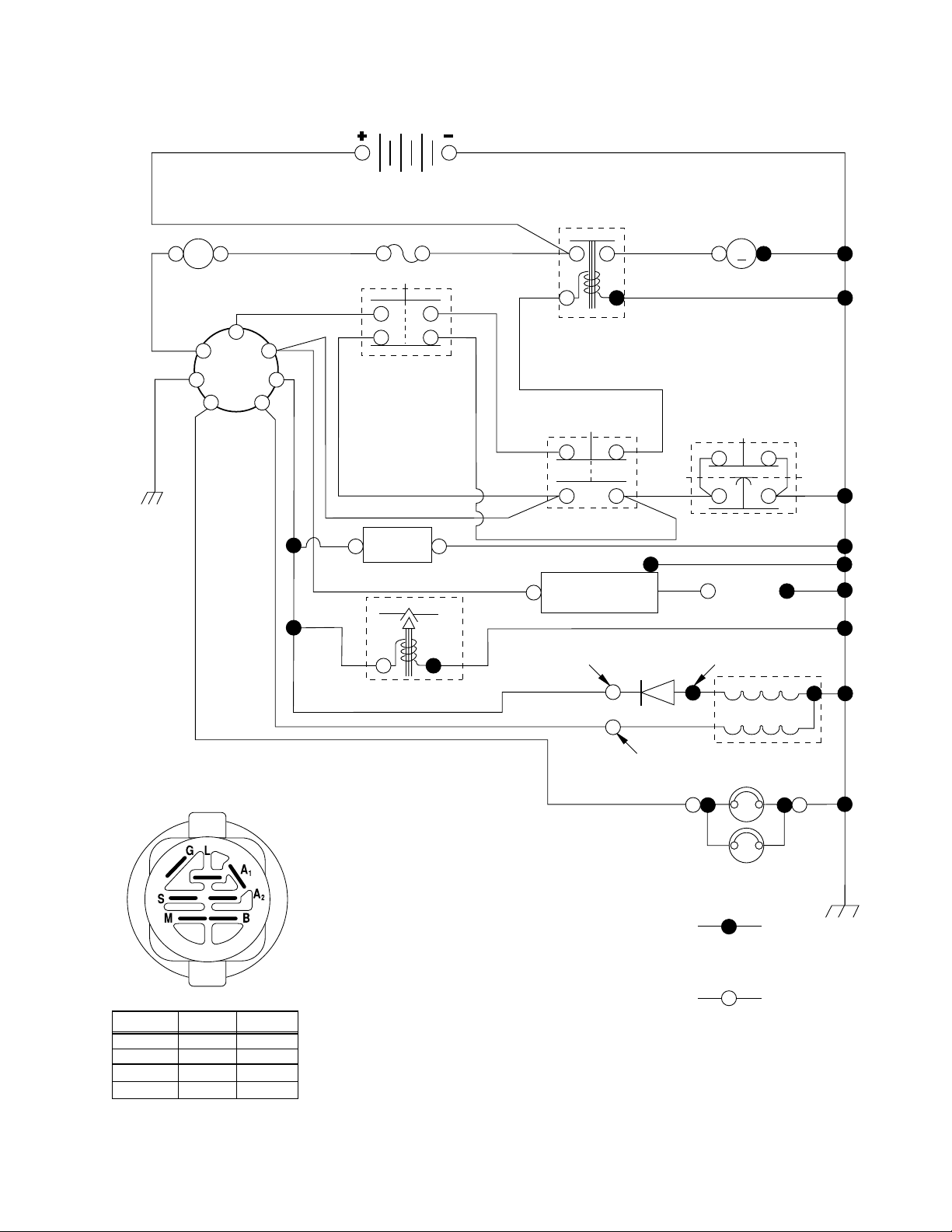
SCHEMATIC
A
AMMETER
(OPTIONAL)
RED
B
G
L
IGNITION
SWITCH
BLACK
RED
BLACK
BATTERY
RED
FUSE
WHITE
RED
M
STARTER
BLACK
SOLENOID
S
M
A1
CLUTCH / BRAKE
(PEDAL UP)
WHITE
A2
SEAT SWITCH
(NOT OCCUPIED)
BLACK
GROUNDING
CONNECTOR
SPARK
PLUG
GAP
(2 PLUGS ON
TWIN CYL. ENGINES)
BLACK
BLUE
BLACK
BLACK
HOUR
METER
(OPTIONAL)
FUEL
LINE
BLACK
WHITE
ATT'MENT CLUTCH
(CLUTCH OFF)
BLACK
IGNITION
UNIT
IGNITION SWITCH
CIRCUITPOSITION
OFF
M+G+A1
B+A1RUN/LIGHT
B+A1RUN
B + S + A1START
“MAKE”
NONE
A2+L
NONE
NONE
28 VOLTS AC MIN. @ 3600 RPM
(CHARGING SYSTEM DISCONNECTED)
DIODE
14 VOLTS AC MIN. @ 3600 RPM (LIGHTS OFF)
FUEL SHUT-OFF SOLENOID
(IF SO EQUIPPED)
ORANGE
CHARGING SYSTEM OUTPUT
3 AMP DC @ 3600 RPM
RED
LIGHTING SYSTEM OUTPUT
5 AMP AC @ 3600 RPM
NOTE
YOUR TRACTOR IS
EQUIPPED WITH A SPECIAL
BROWN
ALTERNATOR SYSTEM.
THE LIGHTS ARE NOT
CONNECTED TO THE
BATTERY, BUT HAVE THEIR
OWN ELECTRICAL SOURCE.
BECAUSE OF THIS, THE
BRIGHTNESS OF THE LIGHTS
WILL CHANGE WITH ENGINE
SPEED. AT IDLE THE LIGHTS
WILL DIM. AS THE ENGINE IS
SPEEDED UP, THE LIGHTS
NON-REMOVABLE
CONNECTIONS
WILL BECOME THEIR BRIGHTEST.
REMOVABLE
CONNECTIONS
WIRING INSULATED CLIPS
NOTE: IF WIRING INSULATED CLIPS WERE REMOVED FOR
SERVICING OF UNIT, THEY SHOULD BE REPLACED TO
PROPERLY SECURE YOUR WIRING.
ALTERNATOR
BLACK
HEADLIGHTS
3
REPAIR PARTS
22
21
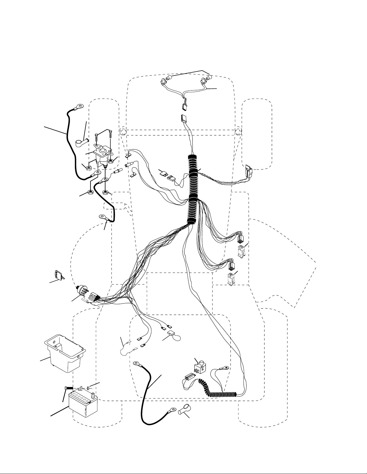
TRACTOR - MODEL NO. 14596 (BA14596B), PRODUCT NO. 964 77 26-02
ELECTRICAL
42
24
41
33
30
27
43
27
25
27
27
26
40
16
16
48
52
29
8
28
27
2
1
90
4

REPAIR PARTS
TRACTOR - MODEL NO. 14596 (BA14596B), PRODUCT NO. 964 77 26-02
ELECTRICAL
KEY PART
NO. NO. DESCRIPTION
1 532 16 34-65 Battery 12 Volt 28 AMP
2 874 76 04-12 Bolt Hex Hd 1/4-20 unc x 3/4
8 532 17 66-89 Box Battery
16 532 17 61-38 Switch Interlock Push-In
21 532 18 37-59 Harness Asm. Light
22 532 00 41-52 Bulb Light
24 532 12 47-80 Cable Battery 6 Ga. 11" red
25 532 14 61-47 Cable Battery 6 Ga. 44" red w/16 wire
26 532 17 51-58 Fuse 20 AMP
27 873 51 04-00 Nut Keps Hex 1/4-20 unc
28 532 12 47-73 Cable Ground 6 Ga. 12" black
29 532 12 13-05 Switch Plunger Nc Gray
30 532 17 55-66 Switch Ign
33 532 14 04-01 Key Ign Molded Generic
40 532 17 97-20 Harness Ign.
41 871 11 04-08 Bolt Blk Fin Hex 1/4 - 20 x 1/2
42 532 13 15-63 Cover Terminal Red
43 532 17 88-61 Solenoid
48 532 14 08-44 Adapter Ammeter Rectangular
52 532 14 19-40 Protection Wire Loop
90 532 18 04-49 Cover Terminal Battery
NOTE: All component dimensions given in U.S. inches.
1 inch = 25.4 mm.
5
REPAIR PARTS
TRACTOR - MODEL NO. 14596 (BA14596B), PRODUCT NO. 964 77 26-02
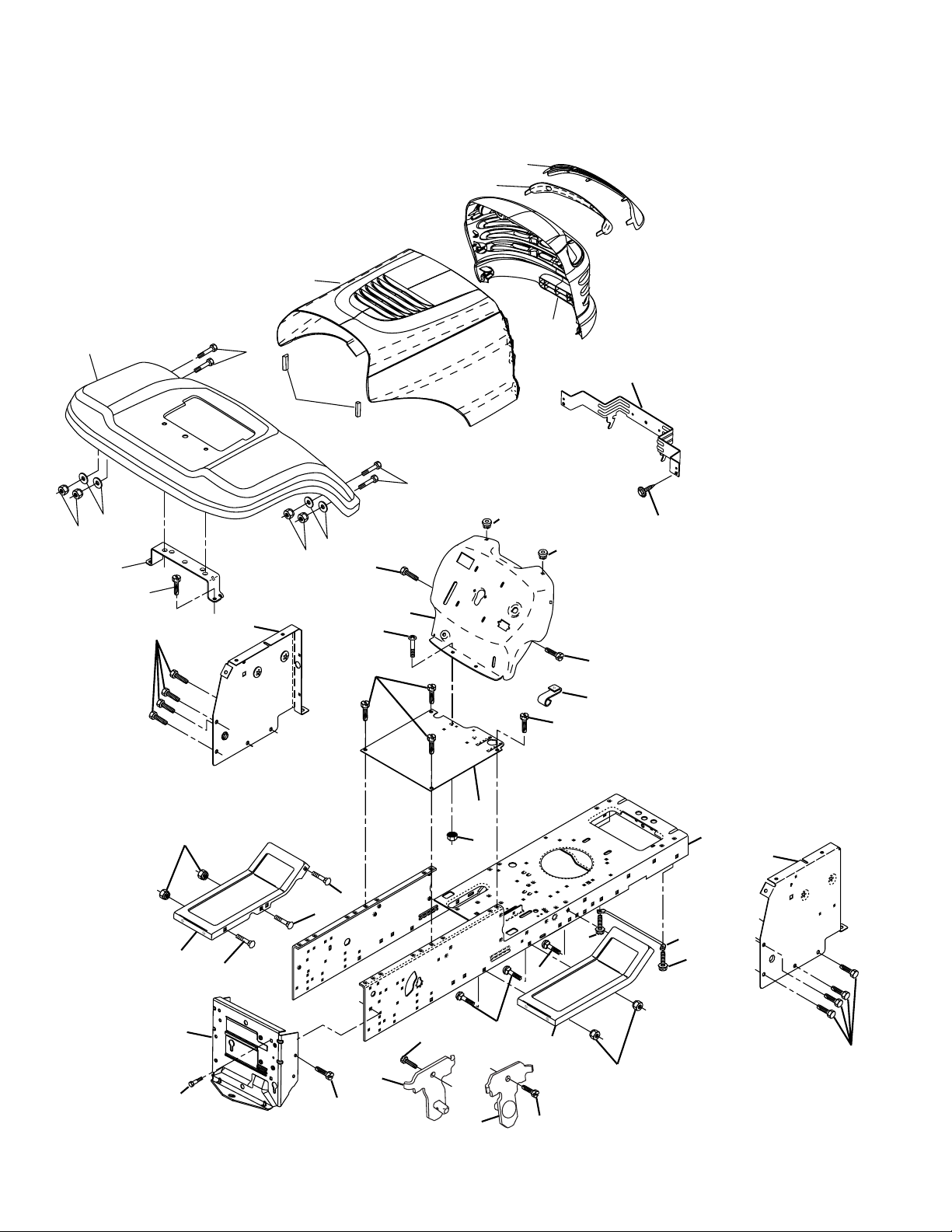
CHASSIS AND ENCLOSURES
29
212
17
28
30
24
39
18
24
26
25
31
209
208
33
26
10
11
26
35
25
209
209
15
209
5
5
9
209
8
209
6
16
37
209
166
1
13
145
37
206
38
35
205
34
208
26
Chassis-Elite_Value_LT_1
2
38
209
205
6

REPAIR PARTS
TRACTOR - MODEL NO. 14596 (BA14596B), PRODUCT NO. 964 77 26-02
CHASSIS AND ENCLOSURES
KEY PART
NO. NO. DESCRIPTION
1 532 17 46-20 Chassis Stamping
2 532 17 65-54 Drawbar
5 532 15 52-72 Bumper Hood/Dash
6 532 18 25-59 Saddle
8 532 12 64-71 Clip Insulator
9 532 18 54-80 Dash P/L
10 872 14 06-08 Bolt Carriage 3/8-16 x 1
11 532 17 49-96 Panel Dash Lh
13 532 18 69-52 Panel Dash Rh
15 874 18 05-12 Screw Mach Trhd 5/16-18 unc x 3/4
16 873 51 05-00 Nut Keps 5/16-18 unc
17 532 18 65-80 Hood LT/PL
18 532 12 69-38 Bumper Hood
24 874 78 06-16 Bolt Fin Hex 3/8-16 unc x 1 Gr. 5
25 819 13 13-12 Washer 13/32 x 13/16 x 12 Ga.
26 873 80 06-00 Nut Lock Hex W/Ins 3/8-16 unc
28 532 18 35-52 Grille/Lens Asm. (Includes #'s 29 and 212)
29 532 18 58-46 Lens LT/PL
30 532 19 10-03 Fender
31 532 13 66-19 Bracket Support Fender
33 532 18 25-07 Footrest LH
34 532 18 25-08 Footrest RH
35 872 11 06-06 Bolt Rdhd 3/8-16 x 3/4
37 817 49 05-08 Screw Thdrol 6/16-18 x 1/2 TYT
38 532 17 57-10 Bracket, Asm. Pivot, Mower Rear
39 532 17 47-14 Bracket Pivot
145 532 15 65-24 Rod Pivot Chassis/Hood
166 532 17 18-75 Screw HWHD Hi-Lo #13-16 x 5/8
205 817 49 06-08 Screw Thdrol 3/8-16 x 1/2
206 532 17 01-65 Bolt Shoulder 5/16-18 TT
208 817 67 06-08 Screw Thdrol 3/8-16 x 1/2
209 817 00 06-12 Screw Hexwsh Thdr 3/8-16 x 3/4
212 532 18 35-50 Insert Lens Refl ect
- - 532 00 54-79 Plug Button
NOTE: All component dimensions given in U.S. inches
1 inch = 25.4 mm
7

REPAIR PARTS
TRACTOR - MODEL NO. 14596 (BA14596B), PRODUCT NO. 964 77 26-02
DRIVE
268
57
120
263
275
10
13
14
112
77
16
52
21
8
263
63
212
12
7
12
18
113
11
30
32
4
3
79
170
6
6
263
26
32
51
30
52
59
61
56
41
5
18
62
6
35
38
39
36
34
66
65
64
50
27
49
47
120
37
70
116
55
202
150
48
151
51
15
96
26
24
19
25
2
77
1
75
74
78
29
76
28
22
26
27
36
35
53
drive-saddle_31
8

REPAIR PARTS
TRACTOR - MODEL NO. 14596 (BA14596B), PRODUCT NO. 964 77 26-02
DRIVE
KEY PART
NO. NO. DESCRIPTION
1 - - - - - - - - - Transaxle, Peerless 206-545C
(Order Parts From Transaxle Manu-
factuer)
2 532 14 66-82 Spring Return Brake T/a Zinc
3 532 12 36-66 Pulley Transaxle 18" tires
4 812 00 00-28 Ring Retainer # 5100-62
5 532 12 15-20 Strap Torque 30 Degrees
6 817 00 05-12 Screw 5/16-18 x 3/4
7 532 16 22-40 Plate Bracket Shift Saddle
8 532 13 16-79 Rod Shift Saddle
10 876 02 04-16 Pin Cotter 1/8 x 1 Cad
11 532 10 57-01 Washer Plate Shf 388 Sq Hole
12 819 15 12-16 Washer 15/32 x 3/4 x 16 Ga.
13 874 55 04-12 Bolt 1/4-28 Unf Gr. 8 W/Patch
14 810 04 04-00 Washer Lock Hvy Helical 1/4
15 874 49 05-44 Bolt Hex Flg Hd 5/16-18 Gr. 5
16 873 80 05-00 Nut lock Hx W/Ins 5/16-18 unc
18 874 78 06-16 Bolt, Fin Hex 3/8-16 unc x 1 Gr. 5
19 873 80 06-00 Nut Lock 3/8-16 Unc
21 532 10 69-33 Knob
22 532 13 08-04 Rod Brake Blk Zinc 26 840
24 873 35 06-00 Nut Hex Jam 3/8-16 unc
25 532 10 68-88 Spring Rod Brake 2 00 Zinc
26 819 13 13-16 Washer 13/32 x 13/16 x 16 Ga.
27 876 02 04-12 Pin Cotter 1/8 x 3/4 Cad
28 532 17 57-65 Rod Brake Parking LT/YT
29 532 07 16-73 Cap Brake Parking Black
30 532 17 49-73 Bracket Mtg Tran sax le
32 874 76 05-12 Bolt Hex Hd 5/16-18 unc x 3/4
34 532 17 55-78 Shaft Asm Pedal Foot
35 532 12 01-83 Bearing Nylon Blk 629 Id
36 819 21 16-16 Washer 21/32 x 1 x 16 Ga.
37 532 12 49-63 Pin Roll 3/16 x 1"
38 532 17 91-14 Pulley Composite
39 872 11 06-22 Bolt RDHD 3/8-16 unc x 2-3/4 Gr. 5
41 532 17 55-56 Keeper Belt Idler Flat
47 532 12 77-83 Pulley Idler V Groove Plastic
48 532 15 44-07 Bellcrank Clutch Grnd Drv Stl
KEY PART
NO. NO. DESCRIPTION
49 532 12 32-05 Retainer Belt Style Spring
50 872 11 06-12 Bolt Carr Sh 3/8-16 unc x 1-1/2 Gr.5
51 873 68 06-00 Nut Crownlock 3/8-16 unc
52 873 68 05-00 Nut Crownlock 5/16-18 unc
53 532 10 57-10 Link Clutch
55 532 10 57-09 Spring Return Clutch 6 75
56 817 06 06-20 Screw 3/8-16 x 1-1/4
57 532 13 08-01 V-Belt Ground Drive 95 25
59 532 16 96-91 Keeper Belt Span Ctr
61 817 12 06-14 Screw 3/8-16 x .875
62 532 12 48-72 Cover Pedal
63 532 18 02-19 Engine Pulley LT/YT
64 532 17 39-37 Bolt Hex 7/16-20 x 4 x Gr. 5 - 1Hr
65 810 04 07-00 Washer Lock Hvy Hlcl Spr 7/16
66 532 15 47-78 Keeper Belt Engine Foolproof
70 532 18 02-18 Guide Belt Mower Drive RH
74 532 13 70-57 Spacer Axle
75 532 12 17-49 Washer 25/32 x 1 1/4 x 16 Ga.
76 812 00 00-01 E-ring #5133-75
77 532 12 35-83 Key Square 2 0 x 1845/ 1865
78 532 12 17-48 Washer 25/32 x 1-5/8 x 16 Ga.
79 532 12 50-96 Key Woodruff #9 3/16 x 3/4
96 532 12 47-88 Retainer Spring 1"
112 819 09 12-10 Washer 9/32 x 3/4 x 10 Ga.
113 532 12 72-85 Strap Torque LT
116 872 14 06-08 Bolt Rdhd Sq Neck 3/8-16 x 1
120 873 90 06-00 Nut Lock Flg. 3/8-16
150 532 17 54-56 Spacer Retainer
151 819 13 32-10 Washer 13/32 x 2 x 10 Ga.
170 532 18 74-14 Keeper Belt T/A
202 872 11 06-14 Bolt RDHD 3/8-16 x 1-3/4 Gr. 5
212 532 14 52-12 Nut Hex Flg Lock
263 817 00 06-12 Screw Hexwsh Thdr 3/8-16 x 3/4
268 532 18 24-02 Guard Muffl er OHV B&S RH
275 819 13 16-14 Washer 13/32 x 1 x 14 Ga.
NOTE: All component dimensions given in U.S. inches
1 inch = 25.4 mm
9

REPAIR PARTS
TRACTOR - MODEL NO. 14596 (BA14596B), PRODUCT NO. 964 77 26-02
STEERING ASSEMBLY
38
12
39
1
41
42
37
37
36
44
51
54
steering_pl.lt_42
91
43
68
29
15
15
15
88
71
68
29
17
82
29
46
8
6
9
2
7
9
5
3
40
47
13
65
46
8
6
9
32
11
26
28
10
30
67
67
67
47
7
9
5
4
43
43
95
8
10

REPAIR PARTS
TRACTOR - MODEL NO. 14596 (BA14596B), PRODUCT NO. 964 77 26-02
STEERING ASSEMBLY
KEY PART
NO. NO. DESCRIPTION
1 532 17 59-04 Wheel Steering
2 532 17 51-31 Axle Asm
3 532 16 98-40 Spindle Asm LH
4 532 16 98-39 Spindle Asm RH
5 532 12 49-31 Bearing Race Thrust Harden
6 532 12 17-48 Washer 25/32 x 1-5/8 x 16 Ga.
7 819 27 20-16 Washer 27/32 x 1-1/4 x 16 Ga.
8 812 00 00-29 Ring Klip #t5304-75
9 532 12 49-37 Bearing Col Strg Blk
10 532 17 51-21 Link Drag
11 810 04 06-00 Washer Lock Hvy Hlcl Spr 3/8
12 873 94 08-00 Nut Hex Jam Toplock 1/2-20 unf
13 532 13 65-18 Spacer Brg Axle Front
15 532 14 52-12 Nut Hex Flange Lock
17 532 18 06-41 Shaft Asm Strg
26 532 12 68-47 Bushing Link Drag Blk LR
28 819 13 14-16 Washer 13/32 x 7/8 x 16 Ga.
29 817 00 06-12 Screw 3/8-16 x 3/4
30 876 02 04-12 Pin Cotter 1/8 x 3/4 Cad
32 532 13 04-65 Rod Tie Wire Form 19 75 Mech
36 532 15 50-99 Bushing Strg
37 532 15 29-27 Screw
38 532 17 59-05 Insert Cap Strg Wh
39 819 18 38-12 Washer 9/16 x 2-3/8 x 12
40 873 54 06-00 Nut Crownlock 3/8-24
41 532 18 67-37 Adaptor Wheel Strg
42 532 16 96-33 Boot Steering Shaft
43 532 12 17-49 Washer 25/32 x 1-1/4 x 16 Ga.
44 532 18 06-40 Extension Steering Shaft LR/LT
46 532 12 12-32 Cap Spindle Fr Top Blk
47 532 18 32-26 Fitting Grease
51 873 54 04-00 Nut Crownlock 1/4-28
54 871 13 04-20 Bolt Hex 1/4-28 unf
65 532 16 03-67 Spacer Brace Axle
67 872 11 06-18 Bolt, Rdhd Sqnk 3/8-16 x 2-1/4
68 532 16 98-27 Axle, Brace
71 532 17 51-46 Steering Asm.
82 532 16 98-35 Bracket Susp Chassis Front
88 532 17 51-18 Bolt Shoulder 7/16-20
91 532 17 55-53 Clip Steering
95 532 18 89-67 Washer Harden .793 x 1.637 x 060
NOTE: All component dimensions given in U.S. inches.
1 inch = 25.4 mm.
11

REPAIR PARTS
TRACTOR - MODEL NO. 14596 (BA14596B), PRODUCT NO. 964 77 26-02
SEAT ASSEMBLY
1
8
8
9
7
5
14
9
7
10
6
22
24
16
25
15
11
13
17
seat_lt.knob_13
KEY PART
NO. NO. DESCRIPTION
1 532 18 87-04 Seat
2 532 18 01-66 Bracket Pivot Seat 8 720
3 871 11 06-16 Bolt Fin Hex 3/8-16 unc x 1
4 819 13 16-10 Washer 13/32 x 1 x 10 Ga
5 532 14 50-06 Clip Push-In
6 873 80 06-00 Nut Hex w/Ins. 3/8-16 unc
7 532 12 41-81 Spring Seat Cprsn 2 250 Blk Zi
8 817 00 06-16 Screw 3/8-16 x 1-1/2
9 819 13 16-14 Washer 13/32 x 1 x 14 Ga.
10 532 18 01-86 Pan Seat
11 532 16 63-69 Knob Seat
12 532 12 12-46 Bracket Mounting Switch
12
2
5
4
3
KEY PART
NO. NO. DESCRIPTION
13 532 12 12-48 Bushing Snap Blk Nyl 50 Id
14 872 05 04-12 Bolt Rdhd Sqnk 1/4-20 x 1-1/2
15 532 13 43-00 Spacer Split 28 x 96 Yel Zinc
16 532 12 12-50 Spring Cprsn 1 27 Blk Pnt
17 532 12 39-76 Nut Lock 1/4 Lge Flg Gr. 5 Zinc
21 532 17 18-52 Bolt Shoulder 5/16-18 unc
22 873 80 05-00 Nut Hex Lock W/Ins 5/16-18
24 819 17 19-12 Washer 17/32 x 1-3/16 x 12 Ga.
25 532 12 70-18 Bolt Shoulder 5/16-18 x 62
NOTE: All component dimensions given in U.S. inches.
1 inch = 25.4 mm
21
12

REPAIR PARTS
TRACTOR - MODEL NO. 14596 (BA14596B), PRODUCT NO. 964 77 26-02
DECALS
14
11
3
8
12
11
3
10
6
20
1
4
2
5
KEY PART
NO. NO. DESCRIPTION
1 532 18 96-97 Decal Steering Wheel
2 532 14 08-37 Decal Saddle Brake Parking
3 532 18 96-91 Decal Hood
4 532 18 95-74 Decal Fender
5 532 18 47-67 Decal HP Engine
6 532 18 04-32 Decal Europe Stand CE
8 532 18 21-66 Decal Mower Cutfi nger
10 532 14 54-98 Decal Read Owner's Manual Syms.
11 532 15 97-36 Decal Chassis Hot Muffl er
WHEELS & TIRES
1
2
6
5,8
4,10
7
3,9
11
KEY PART
NO. NO. DESCRIPTION
12 532 15 97-37 Decal Brake/ Clutch Symbol Lt
14 532 13 68-32 Decal V-Belt Schematic
20 532 14 50-05 Decal Bat Dan/Psn
- - 532 16 25-98 Decal Drawbar
- - 532 13 83-11 Decal Handle Lift Height Adjust
- - 532 18 51-49 Manual Operator's (Euro.)
- - 532 18 52-38 Manual Operator's (Scand)
- - 532 18 51-50 Manual Operator's (E-Bloc)
- - 532 18 94-73 Manual Parts
KEY PART
NO. NO. DESCRIPTION
1 532 05 91-92 Cap Valve Tire
2 532 06 51-39 Stem Valve
3 532 10 62-22 Tire F Ts 15 x 6 0 - 6 Service
4 532 05 99-04 Tube Front (Service Item Only)
5 532 18 33-37 Rim Asm 6" front White Service
6 532 12 49-57 Fit ting Grease (Front Wheel Only)
7 532 12 49-59 Bear ing Flange (Front Wheel Only)
8 532 18 33-38 Rim Asm 8" rear White Service
9 532 10 62-68 Tire R Ts 18 x 9.5-8 C. Service
10 532 12 49-26 Tube Rear (Service Item Only)
11 532 17 50-39 Cap Axle Blk 1 50 x 1 00
- - 532 14 43-34 Sealant, Tire ( 10 oz. Tube)
wheel_1
NOTE: All component dimensions given in U.S. inches
1 inch = 25.4 mm
13

REPAIR PARTS
TRACTOR - MODEL NO. 14596 (BA14596B), PRODUCT NO. 964 77 26-02
ENGINE
2
32
3
72
1
25
78
44
46
81
38
14
78
13
4
33
31
37
33
40
29
OPTIONAL EQUIPMENT
Spark Arrester
KEY PART
NO. NO. DESCRIPTION
1 532 17 05-51 Control Th/ch Flag
2 817 72 04-08 Screw Hex Thd Cut 1/4-20 x 1/2
3 - - - - - - - - Engine B&S Model No. 282H07
(Order Parts From Engine Manufac-
turer)
4 532 13 73-52 Muffl er
13 532 16 52-91 Gasket Eng 1 313 Id Tin Plated
14 532 14 84-56 Tube Drain Oil Easy
23 532 16 98-37 Shield Brn/Dbr Guard
25 532 18 09-45 Control Choke
29 532 13 71-80 Kit Spark Arrestor (Flat Scrn)
31 532 18 49-00 Tank Fuel Front
32 532 14 05-27 Cap Asm Fuel W/sym Vented
45
23
engine-bs.1cyl_38
KEY PART
NO. NO. DESCRIPTION
33 532 12 34-87 Clamp Hose Black
37 532 13 70-40 Line Fuel 20"
38 532 18 16-54 Plug Drain Oil Easy
40 532 12 40-28 Bushing Snap Nyl Blk Fuel Line
44 817 67 04-12 Screw Hexwsh Thdrol 1/4-20 x 3/4
45 817 00 06-12 Screw Hex Wsh Thdrol 3/8-16 x 3/4
46 819 09 14-16 Washer 9/32 x 7/8 x 16 Ga.
72 532 18 39-06 Screw Socket Head 5/16-18 x 1
78 817 06 06-20 Screw 3/8-16 x 1-1/4
81 873 51 04-00 Nut 1/4-20
NOTE: All component dimensions given in U.S. inches
1 inch = 25.4 mm
14

REPAIR PARTS
TRACTOR - MODEL NO. 14596 (BA14596B), PRODUCT NO. 964 77 26-02
MOWER LIFT
5
7
8
13
13
11
19
31
32
31
32
13
4
12
19
3
1
2
6
6
5
4
13
20
15
17
16
18
20
20
20
15
lift-rh.1piece_3
KEY PART
NO. NO. DESCRIPTION
1 532 15 94-61 Wire Asm Inner/Spring W/plunger
2 532 15 94-76 Shaft Asm Lift
3 532 17 89-81 Pin Groove
4 812 00 00-02 E Ring #5133-62
5 819 21 16-21 Washer PLTD 21/32 x 1 x 21 Ga.
6 532 12 01-83 Bearing Nylon Blk 629 Id
7 532 10 94-13 Grip Handle
8 532 12 45-26 Button Plunger Black
11 532 13 98-65 Link Lift LH
12 532 13 98-66 Link Lift RH
13 532 12 46-70 Retainer Spring
KEY PART
NO. NO. DESCRIPTION
15 532 17 32-88 Link Front
16 873 35 08-00 Nut Jam Hex 1/2-13 unc
17 532 17 56-89 Trunnion
18 873 80 08-00 Nut Lock W/wsh 1/2-13 unc
19 532 13 98-68 Arm Suspension Rear
20 532 16 35-52 Spring, Retainer
31 532 16 98-65 Bearing Pvt. Lift
32 873 54 06-00 Nut Crownlock 3/8-24
NOTE: All component dimensions given in U.S. inches
1 inch = 25.4 mm
15

REPAIR PARTS
TRACTOR - MODEL NO. 14596 (BA14596B), PRODUCT NO. 964 77 26-02
MOWER DECK
67
158
185
107
152
89
40
42
56
146
68
148
3
8
108
36
89
36
21
45
55
54
123
113
122
40
150
45
33
31
32
2
110
97
101
96
98
99
100
53
1
109
30
21
88
87
89
26
28
25
24
21
2
2
86
16
2
15
29
21
23
14
3
5
6
19
149
4
11
13
10
21
27
9
8
38_deck-manual-mulch_2
16

REPAIR PARTS
TRACTOR - MODEL NO. 14596 (BA14596B), PRODUCT NO. 964 77 26-02
MOWER DECK
KEY PART
NO. NO. DESCRIPTION
1 532 17 02-80 Mower Deck Assembly
2 872 14 05-06 Bolt
3 532 13 80-17 Bracket Assembly,Sway Bar
4 532 16 99-70 Bracket Sway Bar Deck
5 532 12 46-70 Retainer Spring
6 532 17 80-24 Bar Sway
8 532 85 08-57 Bolt, Hex 3/8-24 x 1.25 Gr. 8
9 810 03 06-00 Washer, Lock Hvy Hlcl 3/8
10 532 14 02-96 Washer, Hardened
11 532 13 41-48 Blade, Mower 38
13 532 13 76-45 Shaft Assembly, Mandrel, Vented
14 532 12 87-74 Housing, Mandrel, Vented
15 532 11 04-85 Bearing, Ball, Mandrel
16 532 17 44-93 Stripper, Vented Mower Deck
19 532 13 28-27 Bolt, Shoulder
21 873 68 05-00 Nut Crownlock 5/16-18
23 532 13 76-07 Bracket, Mower Defl ector
24 532 10 53-04 Cap, Sleeve
25 532 12 37-13 Spring, Torsion, Defl ector
26 532 11 04-52 Nut, Push
27 532 17 59-43 Shield, Defl ector
28 819 11 10-16 Washer 11/32 x 5/8 x 16 Ga.
29 532 10 67-35 Rod, Hinge
30 532 17 39-84 Screw Thdrol
31 532 18 76-90 Washer, Spacer
32 532 15 35-32 Pulley, Mandrel
33 532 17 83-42 Nut, Toplock, Flanged
36 532 13 14-94 Pulley, Idler, Flat
40 873 68 06-00 Nut Crownlock 3/8-16
45 532 12 47-88 Retainer, Spring
53 532 13 08-40 Brake Assembly
54 532 17 85-15 Washer, Hardened
55 532 13 38-40 Idler Arm Assembly
56 532 16 57-23 Spacer, Retainer
KEY PART
NO. NO. DESCRIPTION
67 532 10 69-32 Knob RD 3/8-16 Plstc Thd
68 532 18 02-14 Belt
86 532 12 50-74 Runner, LH
87 532 12 87-72 Runner, RH
88 819 11 12-16 Washer 11/32 x 3/4 x 16 Ga.
89 819 13 13-11 Washer 13/32 x 13/16 x 11 Ga.
96 873 93 06-00 Nut Centerlock 3/8-16
97 874 93 06-20 Bolt 3/8-16 x 1-1/4
98 810 04 06-00 Washer Lock 3/8
99 819 13 20-16 Washer 13/32 x 1-1/4 x 16 Ga.
100 532 13 56-51 Nut Wing
101 532 13 28-03 Cover Mulch 38"
107 532 13 35-02 Spacer, Retainer
108 532 13 35-03 Stiffener, Idler Arm
109 874 76 06-40 Bolt, Hex Head 3/8-16 x 2-1/2
110 532 14 25-87 Upstop Deck Front 38
113 817 06 05-12 Screw 5/16-18 x 3/8
122 532 13 12-89 Rod, Brake, LH
123 532 16 99-71 Rod, Brake, RH
146 532 16 58-91 Bolt Carriage Idler
148 532 16 90-22 Spring Return Idler
149 532 16 58-98 Retainer Spring Yellow Zinc
150 819 09 12-16 Washer 9/32 x 3/4 x 16 Ga.
152 532 17 27-58 Cable Clutch 38 In
158 817 72 04-08 Screw Hex Thd Cut 1/4-20 x 1/2
185 532 18 82-34 Head Asm Cable Clutch
- - 532 13 07-94 Mandrel Assembly (Includes Housing, Shaft, and Shaft Hardware Only
- Pulley Not Included)
- - 532 18 12-09 Mower Deck, Complete (Order
separately mulcher cover 96-101)
NOTE: All component dimensions given in U.S. inches
1 inch = 25.4 mm
17

T
E
C
U
M
S
E
H
®
SERVICE
®
T
E
C
U
M
Issued January 1980
Revised January 1991
H
E
S
POLICY
WARRANTY
LIMITED WARRANTIES
FOR
NEW PEERLESS GEAR POWER TRAIN COMPONENTS
A. Products Warranted
Peerless Gear and Machine Division of Tecumseh Products Company (“Tecumseh”), subject to the limitations contained below,
will, at its option, repair or replace, without charge for parts or labor only, any part of a new Power Train Component (which as used
herein means and includes the transaxle, gear box, trans mis sion, differential and right angle drives, and any part of the Power Train
Component), EXCEPT any new Power Train Component incorporated in equipment used for commercial or rental pur pos es, which is
found upon examination by any Tecumseh Au tho rized Service Outlet or by Tecumseh’s factory in Grafton, Wis con sin, to be DEFECTIVE
IN MATERIAL AND/OR WORKMANSHIP if re ceived by Tecumseh or a Tecumseh Authorized Service Outlet for such examination within
TWO YEARS from the date of sale to the original consumer purchaser of Peerless Series 820, 900, 910, 915, 920, 930 transaxles and
Series 1100 angle drive and ONE YEAR for all other Peerless products. New Power Train Components incorporated in equipment used for
commercial purposes are warranted in the same manner and to the same extent EXCEPT such Power Train Components are warranted
for NINETY (90) DAYS ONLY, and must be received by Tecumseh or by a Tecumseh Au tho rized Service Outlet for such examination
within 90 days from the date of sale to the original purchaser. New Power Train Com po nents Incorporated in equipment used for rental
purposes are warranted in the same manner and to the same extent EXCEPT such Power Train Components are warranted for THIRTY
(30) DAYS ONLY, and must be received by Tecumseh or a Tecumseh Authorized Service Outlet within 30 days from the date of sale to
the original purchaser.
B. Products And Items Not Warranted
1. Alterations or Modifi cations of Power Train Components.
2. Accidents, Normal Maintenance, Failure to follow the Original Equipment Man u fac tur er’s Manual.
This warranty covers only parts of new Power Train Components which are found upon examination to be defective in material
or workmanship as delivered to the original purchaser. This warranty does not cover defects caused by depreciation or damage caused
by normal wear, accidents, improper main te nance, improper use or abuse of the product, failure to follow the instructions contained in
an Instruction Manual for the operation of the Power Train Component and parts. The cost of normal maintenance and replacement of
service items which are not defective shall be paid for by the original purchaser.
C. Securing Warranty Service
Warranty service can be arranged for by contacting either a Tecumseh Authorized Service Outlet (any Tecumseh Registered
Service Dealer, Tecumseh Authorized Service Distributor, or Tecumseh Central Warehouse Distributor) or by contacting Tecumseh, c/o
Service Manager, Engine and Transmission Group Service Division, 900 North Street, Grafton, Wisconsin 53024. Warranty service
can only be performed by a Tecumseh Authorized Service Outlet or by Tecumseh at its factory in Grafton, Wisconsin. At the time of
requesting warranty service, evidence must be presented of the date of sale to the original purchaser. The purchaser shall pay any
charges for making service calls and/or for transporting the product to and from the place where the inspection and/or warranty work
is performed. The purchaser shall be responsible for any damage or loss incurred in connection with the transportation of Power Train
Components and/or part(s) of the Power Train Components submitted for inspection and/or warranty work.
D. Limitation of Damages and Implied Warranties
The foregoing EXPRESSED WARRANTY IS IN LIEU OF ALL OTHER EXPRESS WARRANTIES. Neither Tecumseh nor any
of its affi liates makes any warranties, representations or promises, written or oral, as to the quality of the Power Train Component or any
of its parts, other than as set forth herein.
ANY IMPLIED WARRANTY OF MERCHANTABILITY OR FITNESS FOR A PARTICULAR PURPOSE, TO THE EXTENT THAT
EITHER MAY APPLY TO ANY PART(S) OF POWER TRAIN COMPONENTS, SHALL BE LIMITED IN DURATION TO THE PERIODS
OF THE EXPRESSED WARRANTIES DEFINED IN PARAGRAPH A HEREOF. IN NO EVENT WILL TECUMSEH BE LIABLE FOR ANY
INCIDENTAL, CONSEQUENTIAL OR SPECIAL DAMAGES AND/OR EXPENSES. Some states do not allow limitations on how long
an implied warranty lasts or the exclusion or limitation of incidental or consequential damages, so the above limitation(s) or exclusion(s)
may not apply to you. This warranty gives you specifi c legal rights and you may also have other legal rights which vary from state to
state.
E. No Dealer Warranty
Tecumseh neither assumes nor authorizes any other person, natural or corporate, to assume for Tecumseh any other obligations
or liabilities in connection with or with respect to any part(s) of a Power Train Component. The seller or dealer of part(s) of a Power Train
Component has no authority, whatsoever, to make any representations or promises on behalf of Tecumseh or to modify the terms or
limitations of Tecumseh’s warranty in any way.
18

LIMITED WARRANTY
The Manufacturer warrants to the original consumer purchaser that this product as manufactured is free from defects in materials and work man ship. For a period of one (1) year from date of purchase by the original consumer purchaser, we will repair or
replace, at our option, without charge for parts or labor incurred in replacing parts, any part which we fi nd to be defective due
to materials or workmanship. This Warranty is subject to the following limitations and exclusions.
1. This warranty does not apply to the engine. Please contact your nearest dealer where they will send the machine to the
engine manufacturer.
2. Transportation charges for the movement of any power equipment unit or attachment are the responsibility of the pur chaser. Transportation charges for any parts submitted for replacement under this warranty must be paid by the purchaser
unless such return is requested by your dealer.
3. Battery Warranty: On products equipped with a Battery, we will replace, without charge to you, any battery which we fi nd
to be defective in manufacture, during the fi rst ninety (90) days of ownership. After ninety (90) days, we will exchange the
Battery, charging you 1/12 of the price of a new Battery for each full month from the date of the original sale. Battery must
be maintained in accordance with the instructions furnished.
4. The Warranty period for any products used for rental or commercial purposes is limited to 90 days from the date of original
purchase.
5. This Warranty applies only to products which have been properly assembled, adjusted, operated, and maintained in ac cor dance with the instructions furnished. This Warranty does not apply to any product which has been subjected to alteration,
misuse, abuse, improper assembly or installation, delivery damage, or to normal wear of the product.
6. Exclusions: Excluded from this Warranty are belts, blades, blade adapters, normal wear, normal adjustments, stan dard
hardware and normal maintenance.
7. In case of any problem within the boundaries of this warranty, contact the nearest department store, indicate the model
number, serial number and the date of purchase of your machine. This warranty does not apply to accidental damages. All
implicit warranties are limited to the same time frames. Or contact:
E.M. Services
54 Rue Lambrechts
92400 Courbevoie
France
Telephone: (1) 46678078
Fax: (1) 46678095
THIS WARRANTY DOES NOT APPLY TO INCIDENTAL OR CONSEQUENTIAL DAMAGES. ANY IMPLIED WAR RAN TIES
ARE LIMITED TO THE SAME TIME PERIODS STATED HEREIN.
19

Electrolux Outdoor Products Service Con tacts
BELGIQUE/BELGIË
Electrolux Outdoor Products
Tel: 02 363 0311, Fax: 02 363 0391
CESKÁ REPUBLIKA
Electrolux, spol. S.r.o., oz Electrolux Outdoor Products,
Na Krecku 365 Praha 10 - Horn
Tel: 02/7487 0164, Info-linka: 0800/110 220
Internet: www.partner-fl ymo.cz E-mail: info@husqvarna.cz
DANMARK
Electrolux Outdoor Products, Flymo/Partner A/S,
Lundtoftegrdsvej 93A, DK 2800 Kgs.Lyngby
Tel: 45 87 75 77, Fax 45 93 33 08 www.fl ymo-partner.dk
DEUTSCHLAND
Electrolux Outdoor Products
Tel: 097 21 7640, Fax:097 21 764202
ESTONIA
Electrolux Estonia Ltd (Electrolux Eesti AS)
Tel: (372) 6650010
FRANCE
Electrolux Outdoor Products
Tel 01 46 67 8141, Fax 01 43 34 2491
FINLAND SUOMI
Electrolux Outdoor Products Finland
Tel: 00 39611, Fax: 00 39 612632
ITALIA
McCulloch Italiana s.r.l. - Via Como 72, 23868 Valmadrera
(LECCO) - ITALIA, Tel: 800 017829, Fax: 0341 581671
IRELAND
Electrolux Outdoor Products
Tel: 01 4565222, Fax: 01 4568551
MAGYARORSZÁG
Electrolux Lehel Kft
Tel: 00 36 1 251 41 47
NORGE
Electrolux Outdoor Products
Tel: 69 10 47 90
NEDERLAND
Electrolux Outdoor Products BV
Tel: 0172-468322, Fax: 0172-468219
ÖSTERREICH
HUSQVARNA Zentralwerksttte, Industriezeile 36, 4020 LINZ,
Tel: 0732 770101-60, Fax: 0732 795922
POLSKA
Electrolux Poland Sp. z.o.o. Husqvarna, 01-612 Warszawa
Myslowicka 10/2
Tel:- (22) 8332949
SLOVENIJA
HUSQVARNA-Ges.m.b.H. Nfg. KG, Industriezeile 36, 4020 LINZ,
Tel: 0732 77 01 01-0, Fax: 0732 77 01 01.40
Internet: www.husqvarna.at E-mail: offi ce@husqvarna.co.at
SLOVENSKA
Electrolux Slovakia s.r.o., Borova Sihot 211, 033 01 Lipt. Hradok
Tel: 044 522 14 19, Fax: 044 522 14 18, www.fl ymo-partner.sk
SCHWEIZ/SUISSE/SUIZZERA
Electrolux Outdoor Products
Tel 062 889 93 50 / 889 94 25, Fax 062 889 93 60 / 889 94 35
SVERIGE
Electrolux Outdoor Products, Sverige
Tel: 036 û 14 67 00, Fax: 036 û 14 60 70
UNITED KINGDOM
Electrolux Outdoor Products, United Kingdom
Tel: 01325 300303, Fax: 01325 310339
í Mecholupy
www.electrolux.com/mcculloch
 Loading...