

McCall ROLL-IN, 1-1014 Service Manual
SERVICE MANUAL
REACH-IN &
ROLL-IN
Refrigerators,
Freezers and
Heated Holding
Cabinets
Part #123456
January 2008

Safety Notices
As you work on a McCall reach-in or roll-in, be
sure to pay close attention to the safety notices in
this manual. Disregarding the notices may lead
to serious injury and/or damage to the
equipment.
Throughout this manual, you will see the
following types of safety notices:
WARNING
Text in a Warning box alerts you to a potential
personal injury situation. Be sure to read the
Warning statement before proceeding, and work
carefully.
Text in a Caution box alerts you to a situation in
which you could damage the equipment. Be sure
to read the Caution statement before proceeding,
and work carefully.
CAUTION
Procedural Notices
As you work on a McCall reach-in or roll-in, be
sure to read the procedural notices in this
manual. These notices supply helpful
information which may assist you as you work.
Throughout this manual, you will see the
following types of procedural notices:
Important
Text in an Important box provides you with
information that may help you perform a
procedure more efficiently. Disregarding this
information will not cause damage or injury, but
it may slow you down as you work.
NOTE: Text set off as a Note provides you with
simple, but useful, extra information about the
procedure you are performing.

Table of Contents
Table of Contents
Section 1
General Information.................................................................................................................................1-1
Model Numbers.......................................................................................................................................1-1
How to Read a Serial Number.................................................................................................................1-4
Model/Serial Number Location...............................................................................................................1-5
Warranty..................................................................................................................................................1-5
Warranty Service.....................................................................................................................................1-5
Warranty Certificate ................................................................................................................................1-6
Section 2
Installation.................................................................................................................................................2-1
General.....................................................................................................................................................2-1
Installing the Cabinet...............................................................................................................................2-1
Uncrating .................................................................................................................................................2-2
Leveling the Cabinet................................................................................................................................2-3
Shelf/Tray Slide Installation....................................................................................................................2-3
Electrical Requirements...........................................................................................................................2-4
Electrical Specifications ..........................................................................................................................2-4
Section 3
Operation...................................................................................................................................................3-1
Sequence of Operation.............................................................................................................................3-1
Condensate Water Removal (Refrigerators and Freezers) ......................................................................3-3
Defrost Systems.......................................................................................................................................3-3
Temperature Controls..............................................................................................................................3-4
Loading Shelves (Reach-In Cabinets) .....................................................................................................3-5
Loading Carts (Roll-In Cabinets) ............................................................................................................3-5
Adjustments and Calibrations..................................................................................................................3-6
Section 4
Maintenance ..............................................................................................................................................4-1
Cleaning Recommendations....................................................................................................................4-1
Component Replacement Procedures......................................................................................................4-3
Section 5
Troubleshooting ........................................................................................................................................5-1
Troubleshooting Guide............................................................................................................................5-1
Section 6
Component Check Procedures.................................................................................................................6-1
Main Power Switch..................................................................................................................................6-1
Temperature Control (Thermostat)..........................................................................................................6-1
Light Switch.............................................................................................................................................6-2
Defrost Termination/Fan Delay Switch...................................................................................................6-2
Defrost Timer...........................................................................................................................................6-3
Defrost Heater Element ...........................................................................................................................6-3
Drain Pan Heater Element.......................................................................................................................6-4
Anti-Condensate Door Heaters................................................................................................................6-4
Compressor Overload Protector ..............................................................................................................6-5
Start Relay ...............................................................................................................................................6-5
i

Table of Contents
Compressor Windings .............................................................................................................................6-6
Section 7
Refrigerant Procedures ............................................................................................................................7-1
Refrigerant Recovery/Evacuation & Recharging....................................................................................7-1
Charging Procedures................................................................................................................................7-2
System Contamination Clean-up.............................................................................................................7-3
Refrigerant Re-Use Policy.......................................................................................................................7-5
Section 8
Charts.........................................................................................................................................................8-
1
Charging Specifications – Refrigerators..................................................................................................8-1
Charging Specifications – Freezers.........................................................................................................8-3
Charging Specifications – Dual-Temps (Refrigerators/Freezers) ...........................................................8-4
Section 9
Diagrams....................................................................................................................................................9-
1
Section 1 General Information
Section 1
General Information
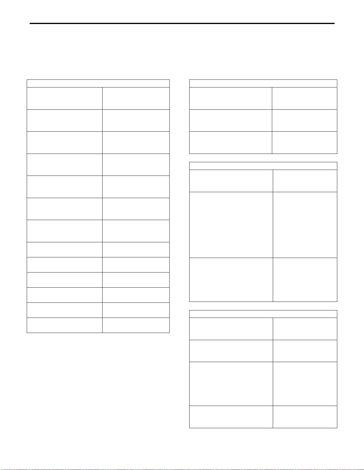
Model Numbers
This manual covers the following models:
Reach-In Refrigerators and Freezers
1 Section
Reach-In Refrigerators
2 Section
Reach-In Refrigerators
3 Section
Reach-In Refrigerators
1 Section
Reach-In Freezers
2 Section
Reach-In Freezers
3 Section
Reach-In Freezers
-10° Freezers 1-1024UF, 1-1045UF
7000 Series
Reach-In Refrigerators
7000 Series
Reach-In Freezers
Narrow Body
Reach-In Refrigerators
Narrow Body
Reach-In Freezers
Wide Body
Reach-In Refrigerators
Wide Body
Reach-In Freezers
1-1020, 1-102001E
2-2020, 2-202001E
4-4020, 4-402001E
1-1045, 1-104501E
2-2045, 2-204501E
4-4045, 4-404501E
1-1070, 1-107001E
2-2070, 2-207001E
4-4070, 4-407001E
1-1020F, 1-1020F01E
2-2020F, 2-2020F01E
4-4020F, 4-4020F01E
1-1045F, 1-1045F01
2-2045F, 2-2045F01
4-4045F, 4-4045F01
1-1070F, 1-1070F01
2-2070F, 2-2070F01
4-4070F, 4-4070F01
2-2024UF, 2-2045UF
4-4024UF, 4-4045UF
7-7020, 7-7045,
7-7070
7-7020FT, 7-7045FT,
7-7070F
1-1020N, 2-2020N,
4-2020N
1-1020F, 2-2020F,
4-4020F
1-1024, 2-2024,
4-4024
1-1024F, 2-2024F,
4-4024F
Pass-Thru Refrigerators
1 Section
Pass-Thru Refrigerators
2 Section
Pass-Thru Refrigerators
3 Section
Pass-Thru Refrigerators
1-1020P
2-2020P
4-4020P
1-1045P
2-2045P
4-4045P
1-1070P
2-2070P
4-4070P
Glass Door Reach-In Refrigerators
1 Section
Glass Door Reach-Ins
2 Section
Glass Door Reach-Ins
3 Section
Glass Door Reach-Ins
1-1020GD,
2-2020GD,
4-4020GD
1-1045GD, 1-1045X,
1-1045PGD,
1-1045XPGD,
2-2045GD, 2-2045X
2-2045PGD,
2-2045XPGD
4-4045GD, 4-4045X
4-4045PGD,
4-4045XPGD
1-1070GD,
1-1070PGD,
2-2070GD,
2-2070PGD,
4-4070GD,
4-4070PGD
Dual Temps
1 Section
Dual Temps
2 Section
Dual Temps
3 Section
Dual Temps
Wide Body Dual Temps DT1-102401E
DT1-102001E
DT2-202001E
DT4-402001E
DT1-1045
DT2-2045
DT4-4045
DT1-1070
DT1-1070F
DT2-2070
DT2-2070F
DT4-4070
DT4-4070F
DT2-202401E
DT4-402401E
1-1
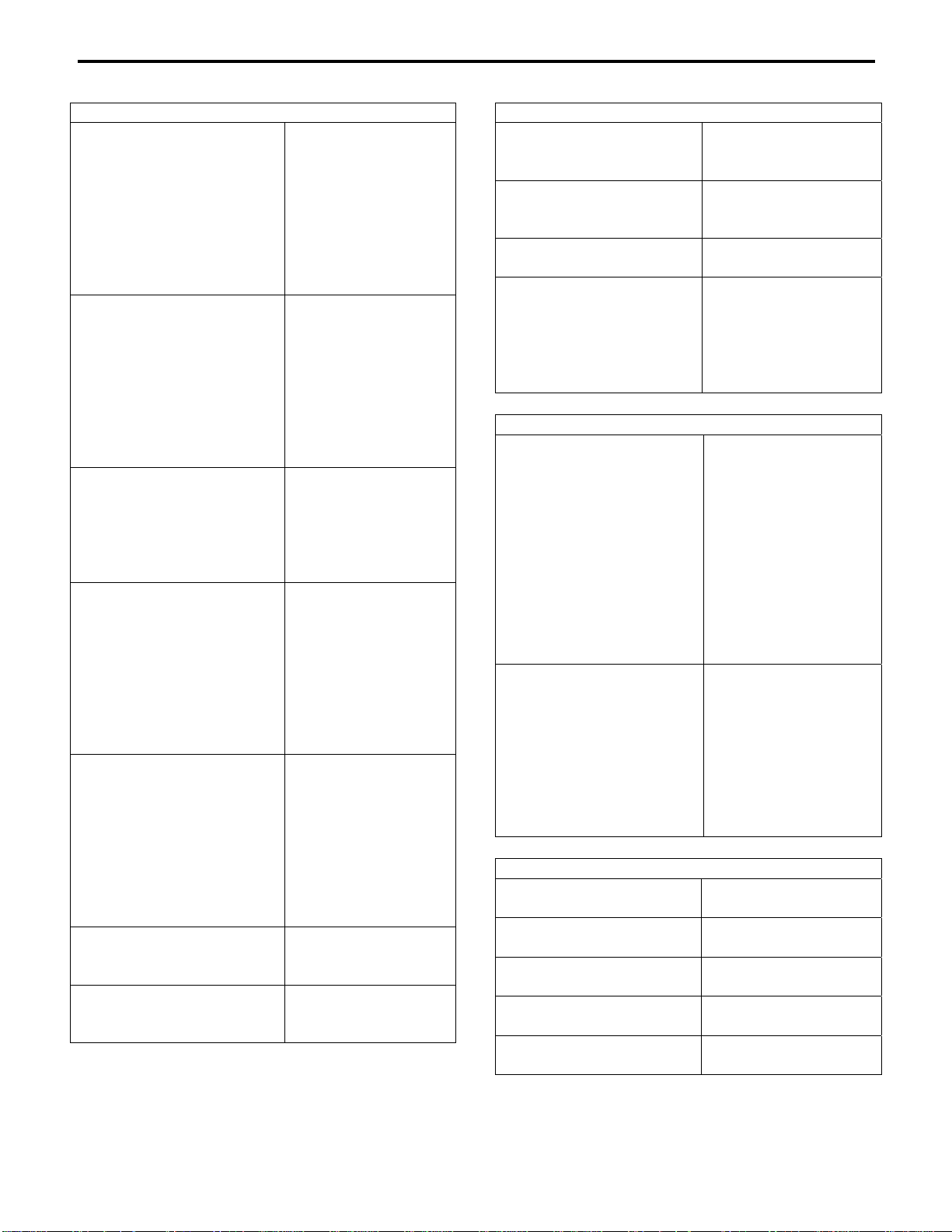
Roll-In Refrigerators and Freezers
Roll-In Refrigerators
(65" cart 1 Section)
Roll-In Refrigerators
(65" cart 2 Section)
Roll-In Refrigerators
(65" cart 3 Section)
Roll-In Refrigerators
(72" cart 1 Section)
Roll-In Refrigerators
(72" cart 2 Section)
Roll-In Freezers
(65" 1 Section)
Roll-In Freezers
(65" 2 Section)
L1-1001
L2-2001
L4-4001
L1-1001RT
L2-2001RT
L4-4001RT
L1-1001GD
L2-2001GD
L4-4001GD
L1-1002
L2-2002
L4-4002
L1-1002RT
L2-2002RT
L4-4002RT
L1-1002GD
L2-2002GD
L4-4002GD
L1-1003
L2-2004
L4-4003
L1-1003GD
L2-2003GD
L4-4003GD
H1-1001
H2-2001
H4-4001
H1-1001RT
H2-2001RT
H4-4001RT
H1-1001GD
H2-2001GD
H4-4001GD
H1-1002
H2-2002
H4-4002
H1-1002RT
H2-2002RT
H4-4002RT
H1-1002GD
H2-2002GD
H4-4002GD
L1-1001FE
L2-2001FE
L2-4001FE
L1-1002FE
L2-2002FE
L4-4002FE
Heated Holding Cabinets
Heated Holding
Cabinets
(1 Section)
Heated Holding
Cabinets
(2 Section)
Narrow Body Heated
Holding Cabinets
Pass Thru Heated Holding
Cabinets
Roll-In Heated Holding Cabinets
Roll-In Heated Holding
Cabinets
(1 Section)
Roll-In Heated Holding
Cabinets
(2 Section)
Bakery Cabinets
Bakery Retarders
(1 Section)
Bakery Retarders
(2 Section)
Bakery Proofers
(1 Section)
Bakery Proofers
(2 and 3 Section)
Pizza Proofer
(2 Section)
Section 1General Information
1020-H
2020-H
4020-H
1-1045-H
2045-H
4045-H
1020N-H
1020-HP
2020-HP
4020-HP
1045-HP
2045-HP
4045-HP
L1-1001H
L2-2001H
L4-4001H
L1-1001HRT
L2-2001HRT
L4-4001HRT
H1-1001H
H2-2001H
H4-4001H
H1-1001HRT
H2-2001HRT
H4-4001HRT
L1-1002H
L2-2002H
L4-4002H
L1-1002HRT
L2-2002HRT
L4-4002HRT
H1-1002H
H2-2002H
H4-4002H
H5-5001
H5-5001RT
H5-5002
H5-5002RT
P5-5001
P-5002
P-5003
H4-4002HD
1-2

Section 1 General Information
Base Mount Refrigerators and Freezers
Base Mount Refrigerators
(24" Wide)
Base Mount Refrigerators
(27.5 " Wide)
Base Mount Freezers
(24" Wide)
Base Mount Freezers
(27.5 " Wide)
1-1014
2-2014
4-4014
1-1018
2-2018
4-4018
1-1014F
2-2014F
4-4014F
1-1018F
2-2018F
4-4018F
1-3
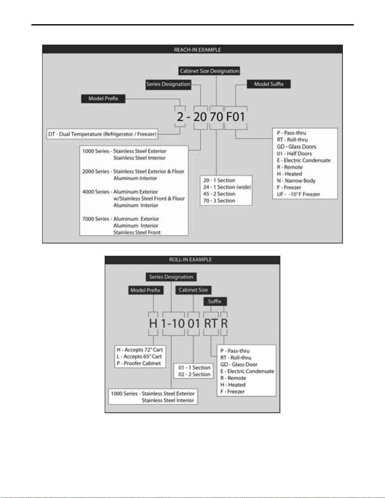
How to Read a Model Number
Section 1General Information
1-4

Section 1 General Information
Model/Serial Number Location
EXCLUSIONS FROM WARRANTY
1. Normal start-up, maintenance, adjustments,
The McCall data plate which includes the model
and cleaning.
number and serial number, as well as important
electrical and technical information, is located on
the left interior wall of the cabinet at
approximately eye level.
For convenience and quick reference, record the
model and serial numbers, voltage, and
installation date in the spaces below:
2. Damage caused by improper installation of
the McCall cabinet as outlined in this
manual.
3. Labor charges resulting from the
inaccessibility of the McCall cabinet.
4. Damage to parts due to misuse, abuse,
neglect, or accidents.
Model Number
Serial Number
Voltage
Installation Date
5. Premium labor rates due to holidays,
overtime, travel time, mileage, etc., not
specifically authorized by McCall prior to
service.
6. Miscellaneous tools or materials charges.
Warranty
Warranty coverage on a McCall reach-in begins
on the date it is installed. Please read the
warranty certificate included with the cabinet for
details.
PARTS COVERAGE
1. McCall warrants the cabinet, refrigeration,
and mechanical components against defects
in materials and workmanship for a period of
one (1) year from the date of original
installation.
2. Refrigerator and freezer compressors are
covered for five (5) years, depending upon
the warranty purchased.
LABOR COVERAGE
Labor is covered for (1) year.
7. Repairs due to modifications to the McCall
cabinet or refrigeration system not authorized
by McCall in writing.
8. Claims for indirect or consequential
damages, including food spoilage or product
loss.
9. Damage due to faulty or incorrect power
supply, floods, storms, or other acts or God.
Warranty Service
To ensure warranty coverage, a qualified service
company, authorized by McCall, must perform
the warranty repair.
If the dealer the McCall reach-in was purchased
from does not perform warranty service, please
contact the McCall Service Department for
assistance.
1-5
Warranty Certificate
McCall warrants to the original Purchaser-User its product as per the following schedule:
All Parts: One year from original installation.
Labor: One year from original installation.
Compressor: One year from original installation.
The obligation of McCall under this warranty is limited to McCall repairing or
replacing, free of cost to Purchaser-User, any part or parts, that to the judgement of
McCall show evidence of defect, and provided that upon McCall authorization, said
part or parts to be returned to McCall, transportation prepaid, for inspection and
judgement. This warranty covers only McCall manufactured self-contained cabinets.
This warranty is issued only to the original Purchaser-User, is not transferable, applies
only to unit installed within the United States of America, its territories and Canada
and is in lieu of all other warranties expressed or implied. McCall neither assumes nor
authorizes any other person to assume for McCall any liability nor herein stated.
McCall shall not be liable for any damage or delays occurring in transit, for any
default or delays in performance caused by any contingency beyond its contract
including wars, government restrictions or restraints, strikes, short or reduced supply
of raw materials, fire, flood or other acts of God, not for damage or loss of any
products, property, loss of income or profit due to malfunctioning of sold unit.
Section 1General Information
Parts & Labor
Warranty
Manufacturing Plant 81 West Holly Street Parsons, TN 38363
Warranty Service: 1-888-REACH-IN Sales Phone: 731-847-5570
Sales FAX: 731-847-9012 Parts FAX: 731-847-5552
www.mccall.com
1-6
Section 2 Installation Instructions
Section 2
Installation
General
CAUTION
These instructions are of the utmost importance in
assuring that the McCall cabinet operates as
designed, and must be followed closely.
Please call your local McCall dealer or the McCall
Service Department if you have any questions
regarding proper installation.
Installing the Cabinet
CAUTION
When selecting a permanent location for the
cabinet, observe the following guidelines. Failure to
do so may cause reduced performance and
efficiency, cause damage, and void your warranty.
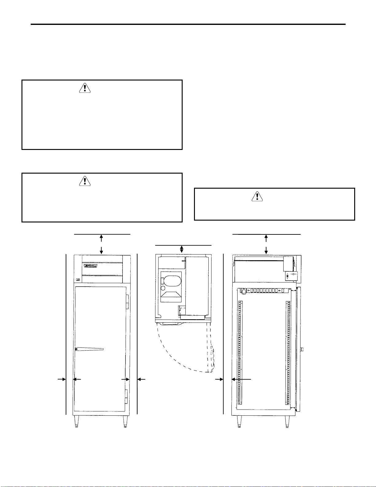
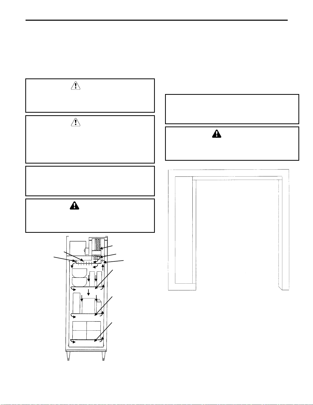
CABINET LOCATION GUIDELINES
• Install the cabinet in an indoor environment only.
• The air temperature entering the refrigerator or
freezer condenser should be between 55°F (13°C)
and 100°F (38°C).
• Allow space for air circulation in the refrigeration
condensing unit compartment on refrigerators and
freezers. The minimum space requirements are:
• 10" (25 cm) on top
• 4" (10 cm) at the back
• 4" (10 cm) on each side
• The floor must be strong enough to support the
weight of the cabinet and product load.
CAUTION
A fully loaded reach-in or roll-in cabinet can weigh
more than 3,000 pounds.
10” 10”
4” 4” 4”
4”
TOP VIEW
SIDE VIEW FRONT VIEW
Cabinet Clearances (Typical Single Door Cabinet Shown)
2-1
E-3042-B
Installation Instructions Section 2
Uncrating
WARNING
Never attempt to tilt the cabinet alone. Always
use two or more people when tilting the cabinet
to remove the shipping skid or to move it
through doorways.
1. Remove the bottom shipping skid using one
of the methods below:
• Lay the cabinet on its back, elevated and
supported by wooden blocks. Remove the
skid mounting bolts and separate the skid
from the cabinet.
• Tilt the cabinet from side to side and
remove the mounting bolts. Support the
weight of the cabinet apart from the skid.
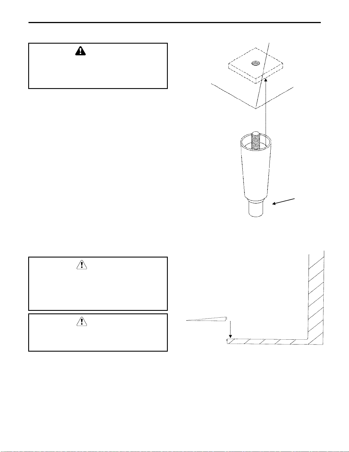
2. Install the legs or casters and torque them to
360 inch-pounds. Refer to the drawing at
right.
NOTE: Roll-in style cabinets do not have legs or
casters. Refer to the drawing at right for ramp
installation.
3. Return the cabinet to the upright position.
Installing Cabinet Legs
THREAD LEVELING
LEG INTO BASE OF
CABINET
THREAD FOOT IN
AS FAR AS
POSSIBLE
SV1342
4. Remove any remaining crating materials.
CAUTION
If the cabinet was placed on its back while
moving it or while removing the bottom
shipping skid, wait at least two hours after
returning the cabinet to the upright position
before starting the refrigeration system.
CAUTION
Never use sharp instruments to cut the plastic or
cardboard crating materials. Damage to the
cabinet exterior may result.
LIP OF RAMP GOES
INTO SLOT AT
FRONT OF CABINET
THRESHOLD
RAMP
CABINET
THRESHOLD
E-3043-B
Ramp Installation
2-2
Section 2 Installation Instructions
Leveling the Cabinet
Shelf/Tray Slide Installation
The cabinet must be leveled after it is positioned
in its permanent location. This ensures proper
door alignment on all cabinets, and adequate
condensate water drainage and proper
refrigeration system operation on refrigerators
and freezers.
Follow the appropriate procedure below.
LEVELING A REACH-IN CABINET
CAUTION
If casters are installed instead of legs, the floor
must be leveled before final positioning of the
cabinet.
1. Place a level on top of the cabinet.
2. Turn the leveling foot of the lowest corner
leg to center the bubble in the level.
3. Adjust each of the other corners until the
bubble is centered and the cabinet is stable.
4. Re-check the cabinet from side to side and
from front to rear with the level.
LEVELING A ROLL-IN CABINET
Roll-in cabinets are designed to sit directly on
the floor without legs or casters.
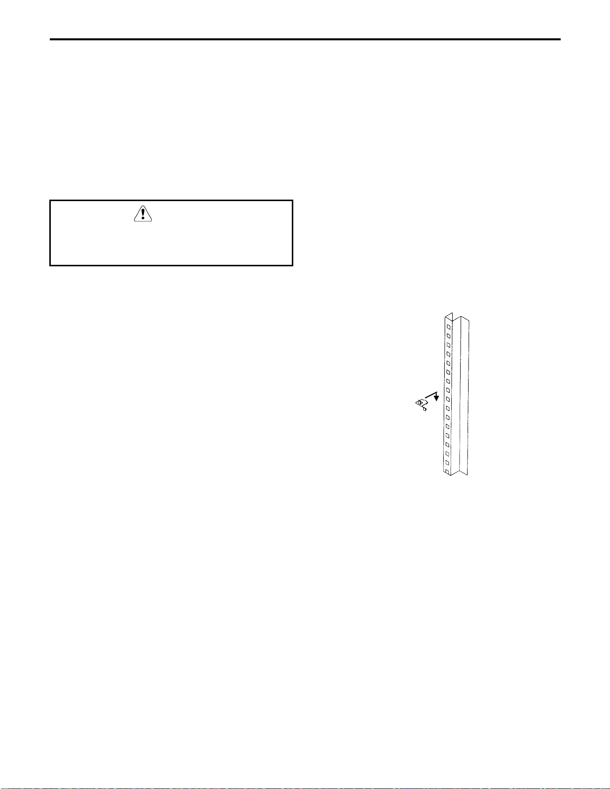
SHELVES
1. Determine the desired shelf location.
NOTE: The shelves may be located at any
position in 1" increments. Optimum spacing is
one shelf near the bottom of the cabinet, one
shelf near center height, and one shelf at eye
level (refer to drawing).
2. Install four clips per shelf, one at each
corner. The shelf clips slip into the 3/8" holes
and slide down.
3. Make sure that the clips are level from side to
side and from front to rear at each corner.
4. Install the shelves with the smaller wires
running from front to back.
SHELF
SUPPORT
SHELF
CLIP
STANDARD
1. Use shims to level the cabinet if necessary.
2. Seal the bottom perimeter of the cabinet to
the floor with NSF-approved silicone.
3. Install the ramp(s). Refer to the drawing on
the previous page.
SER.3
Shelf Installation
2-3
Installation Instructions Section 2
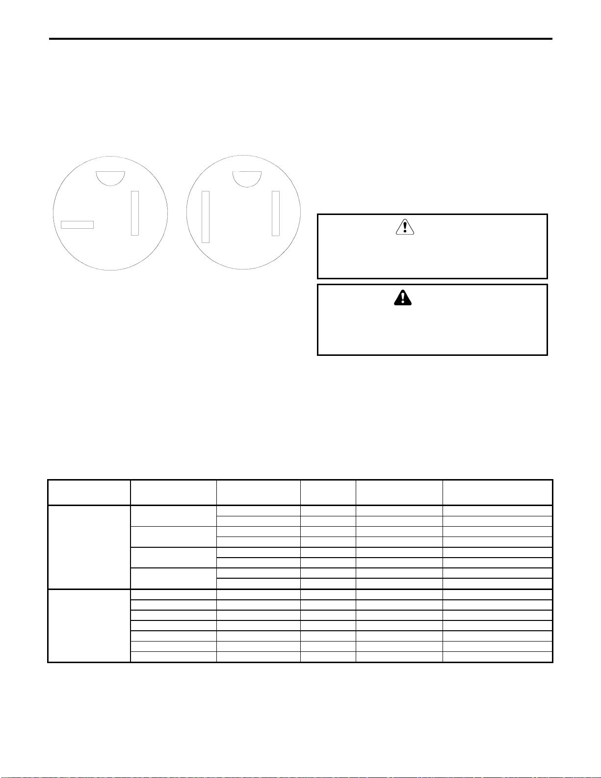
Electrical Requirements
All cord-connected units should be plugged into
a grounded and properly sized electrical outlet
with appropriate overcurrent protection. Refer to
the drawing below for electrical plug
configurations.
5-20P 5-15P
SER.4
5-20P and 5-15P Electrical Plug
Configurations
All permanently connected (hard wired) units are
fitted with a power junction box and 6" pigtail
wires for power connection.
Connect one end of the power line to the pigtail
from the cabinet junction box. Connect the other
end to a properly sized electrical source.
As a rule, the power lines must be enclosed
inside a conduit secured to the power junction
boxes on both ends.
CAUTION
Power installation must be in compliance with
the National Electrical Code and all
applicable local and state codes.
WARNING
Never use an extension cord.
Never alter the power cord or plug supplied
with the cabinet.
After the power source has been connected, turn
on the main power switch. The switch is located
on the cabinet top, behind the front louvered
panel.
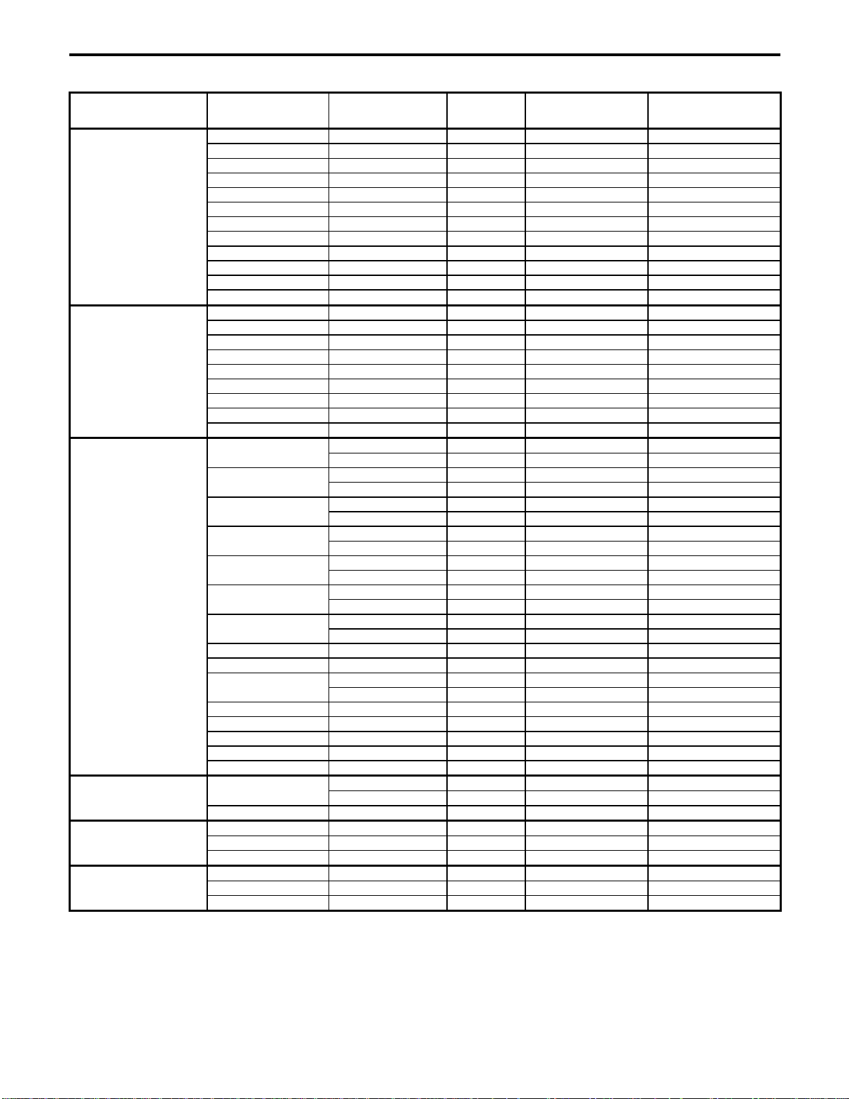
Electrical Specifications
HEATED CABINETS
Product
Type
Reach-In
Heated Cabinets
Roll-In
Heated Cabinets
Self-Contained
Base Models
20H
20HP
45H
45HP
H01H 240/60/1 6.5 15 amp Hard-Wired
H01HRT 240/60/1 6.5 15 amp Hard-Wired
L01H 240/60/1 6.5 15 amp Hard-Wired
L01HRT 240/60/1 6.5 15 amp Hard-Wired
H02H 240/60/1 7.0 15 amp Hard-Wired
L02H 240/60/1 7.0 15 amp Hard-Wired
L02HRT 240/60/1 7.0 15 amp Hard-Wired
Voltage/
Phase/Cycles
115/60/1 14.6 20 amp 5-20P
230/60/1 7.5 15 amp Hard-Wired
115/60/1 14.6 20 amp 5-20P
230/60/1 7.5 15 amp Hard-Wired
115/60/1 14.6 20 amp 5-20P
230/60/1 7.5 15 amp Hard-Wired
115/60/1 14.6 20 amp 5-20P
230/60/1 7.5 15 amp Hard-Wired
Total
Amps
Maximum
Fuse Size
ANSI Electrical
Plug Configuration
2-4
Section 2 Installation Instructions
REFRIGERATORS AND FREEZERS
Product
Type
Reach-In
Refrigerators
Reach-In
Freezers
Roll-In
Refrigerators
Roll-In
Freezers
Base-Mount
Refrigerators
Base-Mount
Freezers
Self-Contained
Base Models
20,20P 115/60/1 8.0 15 amp 5-15P
20GD 115/60/1 11.5 15 amp 5-15P
20PGD 115/60/1 16.0 20 amp 5-20P
45 115/60/1 10.0 15 amp 5-15P
45P 115/60/1 12.0 15 amp 5-15P
45GD 115/60/1 16.0 20 amp 5-20P
45PGD 208/230/60/1 15.0 20 amp Hard-Wired
45XPGD 208/230/60/1 17.0 20 amp Hard-Wired
70 115/60/1 13.3 20 amp 5-20P
70P 208/230/60/1 11.6 15 amp Hard-Wired
70GD 208/230/60/1 15.3 20 amp Hard-Wired
70PGD 208/230/60/1 14.4 20 amp Hard-Wired
20F 115/60/1 12.4 15 amp 5-15P
20FP 115/60/1 15.0 20 amp 5-20-P
20FGDE 115/60/1 16.0 20 amp 5-20-P
45F 115/60/1 16.0 20 amp 5-20-P
45FP 208/230/60/1 ---- 15 amp Hard-Wired
45FGD 208/230/60/1 ---- 20 amp Hard-Wired
70F 208/230/60/1 ---- 25 amp Hard-Wired
70FP 208/230/60/1 ---- 25 amp Hard-Wired
70FGD 208/230/60/1 ---- 25 amp Hard-Wired
H01
HO1RT
H01GD
L01
L01RT
L01GD
H02
H02RT 208/230/60/1 ---- 20 amp Hard-Wired
H02GD 208/230/60/1 ---- 20 amp Hard-Wired
L02
L02RT 208/230/60/1 ---- 15 amp Hard-Wired
L02GD 208/230/60/1 ---- 20 amp Hard-Wired
H03 208/230/60/1 ---- 20 amp Hard-Wired
L03 208/230/60/1 ---- 20 amp Hard-Wired
L03GD 208/230/60/1 ---- 25 amp Hard-Wired
L01FE
L02FE 208/230/60/1 ---- 25 amp Hard-Wired
14 115/60/1 10.0 15 amp 5-15P
18 115/60/1 10.0 15 amp 5-15P
36 115/60/1 12.0 15 amp 5-15P
14F 115/60/1 12.0 15 amp 5-15P
18F 115/60/1 12.0 15 amp 5-15P
36F 115/60/1 15.0 20 amp 5-20P
Voltage/
Phase/Cycles
115/60/1 12.0 15 amp 5-15P
208/230/60/1 7.5 15 amp Hard-Wired
115/60/1 12.0 15 amp 5-15P
208/230/60/1 7.8 15 amp Hard-Wired
115/60/1 13.1 15 amp 5-15P
208/230/60/1 9.0 15 amp Hard-Wired
115/60/1 12.0 15 amp 5-15P
208/230/60/1 7.5 15 amp Hard-Wired
115/60/1 12.0 15 amp 5-15P
208/230/60/1 7.8 15 amp Hard-Wired
115/60/1 13.1 15 amp 5-15P
208/230/60/1 9.0 15 amp Hard-Wired
115/60/1 12.0 15 amp 5-15P
208/230/60/1 9.1 15 amp Hard-Wired
115/60/1 12.0 15 amp 5-15P
208/230/60/1 9.1 15 amp Hard-Wired
115/60/1 16.0 20 amp 5-20P
208/230/60/1 10.6 20 amp Hard-Wired
Total
Amps
Maximum
Fuse Size
ANSI Electrical
Plug Configuration
2-5

Installation Instructions Section 2
THIS PAGE INTENTIONALLY LEFT BLANK
2-6

Section 3 Operation
Section 3
Operation
Sequence of Operation
REFRIGERATORS - SELF-CONTAINED
COOLING CYCLE
With the main ON/OFF switch in the ON
position, the current flows, energizing the
evaporator fan motors.
Current also flows through the closed contacts of
the temperature control, energizing the
condenser fan motor and the compressor.
OFF CYCLE
When the temperature control senses the proper
temperature, it opens, shutting off the
refrigeration system.
The refrigeration system remains off until the
temperature control senses approximately 38°F
(3.3°C). (This also keeps the evaporator
defrosted.) At that time, the temperature control
closes and starts the refrigeration system.
REFRIGERATORS - REMOTE
COOLING CYCLE
With the main ON/OFF switch in the ON
position, the current flows, energizing the
evaporator fan motors.
Current also flows through the closed contacts of
the temperature control, energizing the liquid
line solenoid valve. The increase in suction
pressure causes the contacts on the low pressure
switch to close, energizing the refrigeration
system.
OFF CYCLE
When the temperature control senses the proper
temperature, it opens, shutting off the liquid line
solenoid valve. The drop in suction pressure
causes the low pressure switch to open, deenergizing the refrigeration system.
The refrigeration system remains off until the
temperature control senses approximately 38°F
(3.3°C). (This also keeps the evaporator
defrosted.) At that time, the temperature control
closes and starts the refrigeration system.
3-1

Operation Section 3
FREEZERS - SELF-CONTAINED
FREEZERS - REMOTE
COOLING CYCLE
With the main ON/OFF switch in the ON
position, the current flows, energizing the
automatic defrost time clock.
Current also flows through the closed contacts of
the temperature control, energizing the
condenser fan motor(s) and the compressor.
With contact N closed on the automatic defrost
time clock, current will flow through the
normally open (N.O.) light/fan switch contacts
(with the door closed).
When the evaporator coil temperature reaches 30
to 35°F (-1.1 to 1.7°C), the defrost end and fan
delay thermostat closes, energizing the
evaporator fans.
DEFROST CYCLE
At preset times on the automatic defrost time
clock, the contacts switch to defrost the
evaporator. Contact N opens, de-energizing the
evaporator fan motor(s). Contact #4 opens, deenergizing the refrigeration system. Contact #1
closes, energizing the evaporator defrost heater.
As the evaporator temperature rises, the defrost
end and fan delay thermostat opens to terminate
the defrost cycle. Contact #1 opens, deenergizing the defrost heater. Contacts N and #4
close, energizing the refrigeration system.
OFF CYCLE
When the temperature control senses the proper
temperature, it opens, shutting off the
refrigeration system.
COOLING CYCLE
With the main ON/OFF switch in the ON
position, the current flows, energizing the
automatic defrost time clock.
Current also flows through the closed contacts of
the temperature control, energizing the liquid
line solenoid valve. The increase in suction
pressure closes the contacts on the low pressure
switch, energizing the refrigeration system.
With contact N closed on the automatic defrost
time clock, current flows through the normally
open (N.O.) light/fan switch contacts (with the
door closed).
When the evaporator coil temperature reaches 30
to 35°F (-1.1 to 1.7°C), the defrost end and fan
delay thermostat closes, energizing the
evaporator fans.
DEFROST CYCLE
At preset times on the automatic defrost time
clock, the contacts switch to defrost the
evaporator. Contact N opens, de-energizing the
evaporator fan motor(s). Contact #4 opens, deenergizing the refrigeration system. Contact #1
closes, energizing the evaporator defrost heater.
As the evaporator temperature rises, the defrost
end and fan delay thermostat opens to terminate
the defrost cycle. Contact #1 opens, deenergizing the defrost heater. Contacts N and #4
close, energizing the refrigeration system.
OFF CYCLE
When the temperature control senses the proper
temperature, it opens, shutting off the liquid line
solenoid valve. The drop in suction pressure
causes the low pressure switch to open, deenergizing the refrigeration system.
3-2
Section 3 Operation
Condensate Water Removal
(Refrigerators and Freezers)
McCall cabinets are equipped with condensate
vaporizer systems.
Remote units use an electrically operated system.
Most self-contained units use energy-saving hot
gas supplied by the refrigeration system lines.
No drain connection is required.
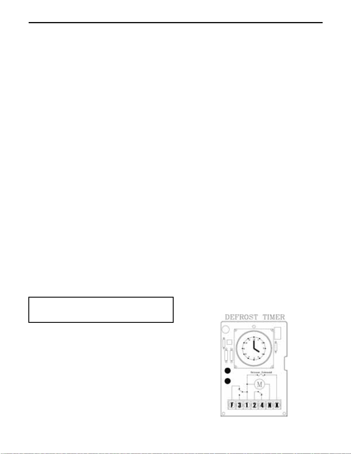
Defrost Systems
NOTE: If the defrost termination thermostat fails
to close, the fail safe setting on the timer will
terminate the defrost.
The timer starts the defrost cycle automatically at
predetermined times. A setting of two to four
defrost cycles per day is typical. For heavier frost
loads, additional cycles may be required.
When the defrost cycle begins:
1. Switch 2 to 4 opens in the time clock,
breaking the circuit to the room thermostat,
liquid line solenoid, and evaporator fan
GENERAL
Refrigerator coils are kept below the freezing
point (32°F). During compressor “off” time, the
evaporator fan continues to circulate 38°F
refrigerator compartment air through the
evaporator coil. This air circulation raises the
coil temperature above the freezing point,
melting any frost that may have accumulated.
motors. This allows the compressor to pump
down and shut off. Simultaneously, switch 1
to 3 closes in the timer, energizing the
defrost heaters.
2. The heaters increase the coil temperatures
above 32°F, melting the frost off the coil.
3. When the coil warms to approximately 55°F,
the defrost termination thermostat closes and
The run-off water is drained into the vaporizer
pan and is evaporated by the hot gas refrigeration
line during compressor “on” time.
Freezer coils are defrosted electrically at userdetermined times.
NOTE: A freezer’s evaporator fans do not run
immediately upon start-up or during and
immediately following the defrost cycles. The
fans start when the coil reaches a cold
temperature. This prevents the fans from blowing
heated air on the stored products.
energizes the switching solenoid in the timer.
At this time, switch 1 to 3 in the timer opens,
terminating the defrost heaters.
Simultaneously, switch 2 to 4 closes in the
time clock, energizing the temperature
control circuit.
4. Suction pressure rises, the low pressure
control closes, and the compressor starts.
5. The fan relay closes when the coil
temperature reaches approximately 30°F.
This energizes the fan motors.
DEFROST SETTINGS
Important
Set the defrost timer to defrost the reach-in during
the lowest usage periods.
Each defrost tripper represents 15 minutes of
defrost time. At the factory, the timer is set for
four automatic defrost cycles daily at 4:00AM,
10:00AM, 4:00PM, and 10:00PM respectively.
Each defrost cycle is programmed for 45 minutes
duration. Upon startup, set the clock for the
correct time of day by rotating the clock face
until the correct time is at the arrow on the face
of the timer.
3-3
6. The system operates in the refrigeration cycle
until another defrost cycle is initiated by the
timer.
Operation Section 3
Temperature Controls
REFRIGERATORS AND FREEZERS
The temperature controls are factory-set to
maintain an average temperature of 38°F in
refrigerators, and an average temperature of 0°F
in freezers.
The temperature variance is 6-8 degrees. A
freezer should run between -2 to -3°F and +3 to
+4°F. A refrigerator should run between +35 to
+36°F and +41 to +42°F.
For a different cabinet temperature setting, turn
the temperature control knob, located behind the
front cabinet louver.
CAUTION
Setting the temperature control to the coldest
setting may cause the coil and/or air ducts to
freeze and ice up. This will eventually result in a
warmer cabinet temperature.
If ice accumulation occurs and the temperature is
lower than the guidelines, turn the control knob to
a warmer setting.
CAUTION
Allow the reach-in to reach proper operating
temperature before filling it with product. Do not
place hot or steaming foods in the cabinet.
REACH-IN
HEATED CABINETS
Single-section reach-in heated cabinets are
designed to maintain a temperature of up to
170°F. Two-section and three-section cabinets
can maintain a temperature of up to 140°F.
The temperature control knob is located on the
top front louver. Turn the knob clockwise to
raise the temperature, and counterclockwise to
lower the temperature.
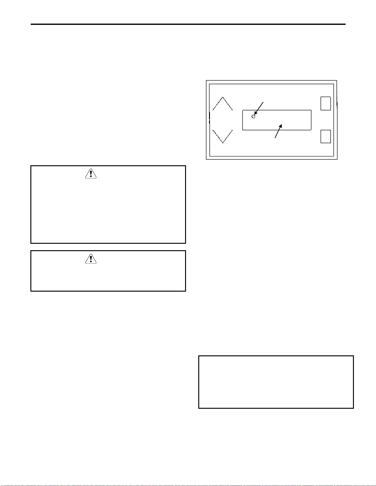
ROLL-IN HEATED CABINETS
The temperature control panel on a roll-in heated
cabinet is located on the front louver panel.
LED (ILLUMINATED
WHEN HEAT IS ON)
DISPLAY
°F
SET
Roll-In Heated Cabinet Control Panel
To adjust the interior cabinet temperature:
1. Make sure that the main power switch
(located behind the front louver) and the
on/off switch (on the front louver panel) are
both ON.
2. Press the SET pad once. “SP1” is displayed.
3. Press the SET pad again to display the
numerical set point.
4. To change the temperature, press the up or
down arrow.
5. Press the SET pad repeatedly until the
display goes blank. After 5 seconds, the
screen will display the interior temperature of
the cabinet.
NOTE: While the heating element is energized, a
small LED light is illuminated between the first
2 digits of the temperature display.
Important
If the programming sequence is interrupted for
more than 15 seconds, or not completed through
Step 5 (blank screen), the unit will automatically
revert to the temperature display mode without
accepting the new setting.
3-4
Section 3 Operation
Loading Shelves (Reach-In
Loading Carts (Roll-In Cabinets)
Cabinets)
For maximum operating efficiency, load the
shelves with space between the stored items.
This allows air to circulate properly. Refer to the
drawing below.
CAUTION
Do not store more than 250 pounds of product on
any shelf, and no more than 800 pounds of
product per cabinet.
Store products with high acid content (such as
lettuce, other fresh vegetables or fruits, salad
dressings, etc.) in closed containers. This will
prevent corrosion on the evaporator coil and other
metal parts in the air distribution system.
Uncovered food will dehydrate much more
rapidly than covered food. For best food quality,
always store in covered container.
In a heated cabinet, the shelves, interior cabinet
surfaces and food containers are hot. Use care
when storing or removing product.
CAUTION
Important
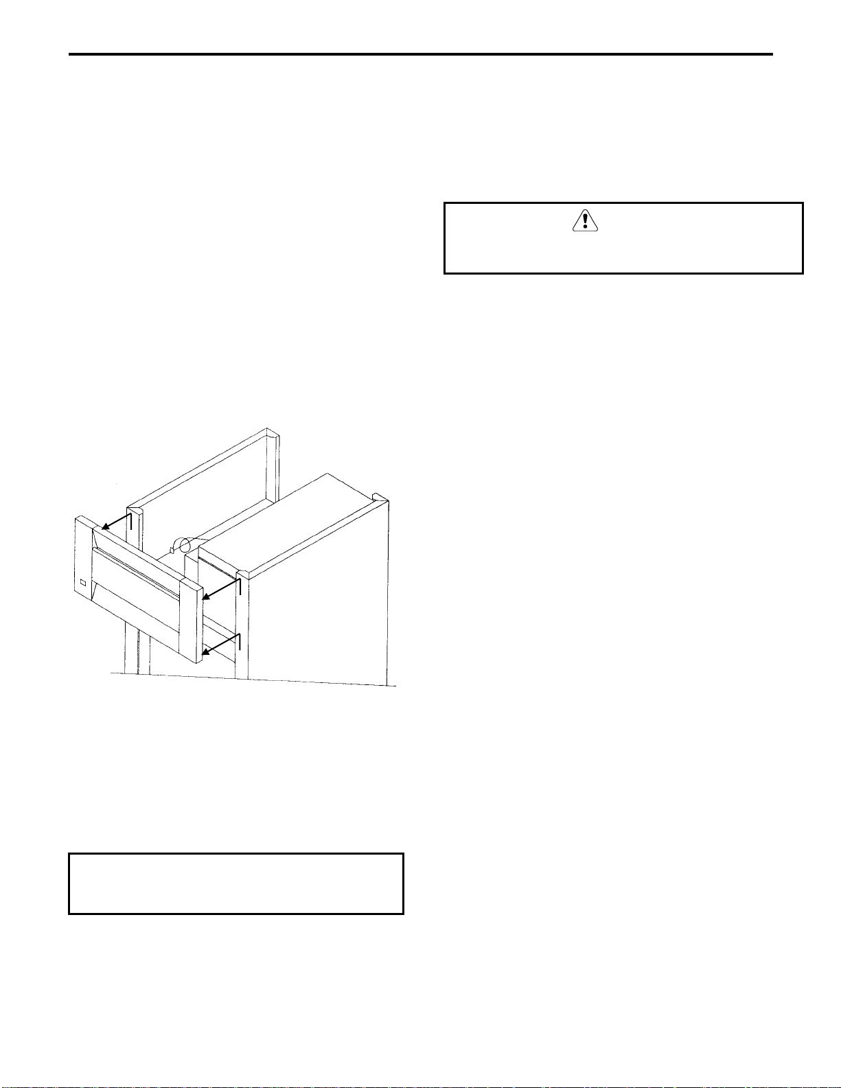
WARNING
Roll-in cabinets are designed to accept carts of
pre-heated food (heated units) or pre-chilled or
frozen food (refrigerators or freezers).
Cart guides have been installed in each cabinet
bay to keep the cart away from the interior walls.
Center the cart(s) in the bay(s) for best air
circulation. Refer to the drawing below.
Important
Uncovered food will dehydrate much more rapidly
than covered food. For best food quality, always
store in covered containers.
WARNING
In a heated cabinet, the cart(s), interior cabinet
surfaces and food containers are hot. Use care when
storing or removing product.
DAMPER
SUPPLY
AIR
Loading the Shelves
EVAPORATOR
COIL
EVAPORATOR
FAN
SHELF
SHELF
SHELF
RETURN
AIR
SER.5
Positioning a Cart in the Cabinet
3-5
Operation Section 3
A
Adjustments and Calibrations
ADJUSTMENTS
Cabinet doors may require some adjustment after
a period of usage, depending upon the frequency
of door openings. This is normal. Follow the
appropriate procedure below:
Solid Door Adjustment
1. Remove the metal hinge covers that conceal
the three hinge mounting screws. Gently pry
it off with a flat-bladed screwdriver.
HINGE
MOUNTING
SCREWS
DOOR
HINGE
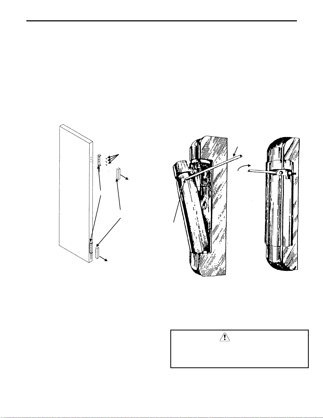
Glass Door Adjustment
To adjust the spring tension:
1. Locate the adjustment bushing on the hinges.
This bushing is on top of the hinge for righthand doors and on the bottom for left-hand
doors.
2. Insert a small nail (1/8") into a hole in the
adjustment bushing. Wind the bushing
clockwise until the pin can be removed from
the bushing.
INSERT A
SMALL NAIL
TURN
CLOCKWISE
HINGE
COVER
E-3044-B
Hinge/Hinge Cover
2. Loosen the three hinge mounting screws
approximately two rotations, using a Phillips
screwdriver.
3. While a second person firmly pushes the
door closed to the front face of the cabinet,
re-tighten the screws.
4. Re-install the hinge covers.
DJUSTMENT
BUSHING
Hinge Adjustment
3. Continue winding the bushing clockwise
until the desired tension is achieved.
4. Re-insert the bushing pin.
CAUTION
Do not over-tighten the hinge spring.
McCall recommends adjusting the hinge
adjustment bushings one hole at a time.
3-6
Section 3 Operation
CALIBRATIONS
Occasionally, the rigors of shipping and
installation can shift the thermometer out of
proper adjustment.
If the accuracy of the thermometer is in question,
place another thermometer inside the cabinet at
approximately mid-height and compare the
readings.
If the thermometer requires adjustment, follow
the appropriate procedure below.
4. Locate the blue calibration screw in the upper
right corner of the thermometer. Turn the
screw clockwise to increase the temperature
reading or counterclockwise to decrease the
reading.
CAUTION
Do not apply extreme pressure to the adjustment
screw. Damage to the digital display may result.
Digital Thermometer Calibration
1. Lift up on the front cabinet louver (about
5/8" to 1") to disengage the keyhole slots
from the four screws in the cabinet front.
Remove the louver.
5. Reset the two dip switches to their original
position.
6. Re-install the front louver to the cabinet.
Position the keyhole slots in the louver rear
on the four screws in the cabinet front. Push
it straight down until the louver locks into
place.
LIFT UP
AND OFF
SER.1
Removing the Front Cabinet Louver
2. Cut the plastic tie holding the thermometer
probe wire, taking care not to cut the wire.
This releases the full length of the probe
wire, allowing the louver to be lowered to the
floor.
7. Re-tie or tape the excess length of probe lead
wire.
Dial Thermometer Calibration
1. Gently pry off the clear thermometer cover
lens with a small flat-bladed screwdriver.
2. While carefully holding the dial indicator
needle with one hand, turn the slotted center
pivot with a flat-bladed screwdriver. Turn
clockwise to decrease the reading and
counterclockwise to increase the reading.
3. Replace the clear thermometer cover lens by
pressing it into place around the perimeter.
Important
Do not disconnect the probe wire from the rear
of the thermometer display.
3. Locate the two dip switches on the
thermometer rear. Set both switches to ON.
3-7

Operation Section 3
THIS PAGE INTENTIONALLY LEFT BLANK
3-8
Section 4 Maintenance
Section 4
Maintenance
Cleaning Recommendations
EXTERIOR
Clean cabinet exterior surfaces with a solution of
mild soap and water. To minimize streaking,
follow with a fresh water rinse.
If stainless steel becomes discolored, scrub only
in the direction of the finished grain.
For high shine, see your kitchen equipment
dealer for a high-quality stainless steel polish.
CAUTION
Do not use steel wool, caustic soap, or abrasive
cleaners, as these may damage the metal finish.
Alcohol-based cleaners may damage the nylon
door cams.
INTERIOR
Clean cabinet interior surfaces with warm water
and baking soda, applied with a cloth or sponge.
The air duct and shelf support standards can be
removed without special tools to facilitate
cleaning.
Wash door gaskets weekly with a mild soap and
water solution, followed by a fresh water rinse.
While cleaning, check the door gaskets for
proper sealing. Adjust if needed.
CAUTION
Never use cleaners that are not approved for use
where food may come into contact with cabinet
interior surfaces.
CAUTION
Do not use steel wool, caustic soap, or abrasive
cleaners, as these may damage the metal finish.
4-1
Maintenance Section 4
CLEANING THE CONDENSER COIL
(REFRIGERATORS AND FREEZERS)
WARNING
Disconnect electric power before cleaning.
For efficient operation, it is very important to
Method 1
Remove light build-up with a soft brush or a
vacuum with a brush attachment. Brush the
condenser fins from top to bottom, not from side
to side. Shine a light through the fins to check
for dirt inside the condenser.
clean the condenser coil surface and keep it free
of dust, dirt, and lint. McCall recommends
checking the condition of the condenser coil
once a month.
The condensing unit fan draws dust, lint and
Method 2
Clean moderately dirty fins with compressed air,
blowing from the inside out. Follow by brushing,
if necessary.
small particles to the condenser coil, where it
forms a “blanket” on the coil surface. This is
normal and should be periodically removed.
CAUTION
Failure to clean and maintain the condenser coil
properly will result in reduced air circulation
through the condenser fins. This will cause
Method 3
Clean with a commercial condenser coil cleaner,
available from a kitchen equipment dealer.
Follow the directions and precautions supplied
with the cleaner.
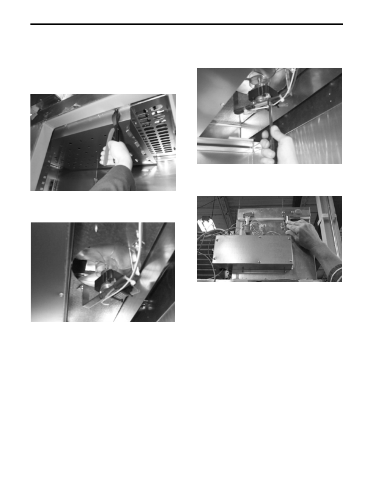
After cleaning, straighten any bent condenser
fins with a fin comb.
reduced efficiency, high operating pressures, and
possible shortened compressor life.
CONDENSER CLEANING PROCEDURES
One or more of the following methods may be
used to clean the condenser coil surface,
depending upon the extent of the build-up on the
fins.
COMB
DOWN
ONLY
CONDENSER
FIN COMB
WARNING
Condenser fins are sharp. Use care when working
around them.
4-2
Using a Fin Comb
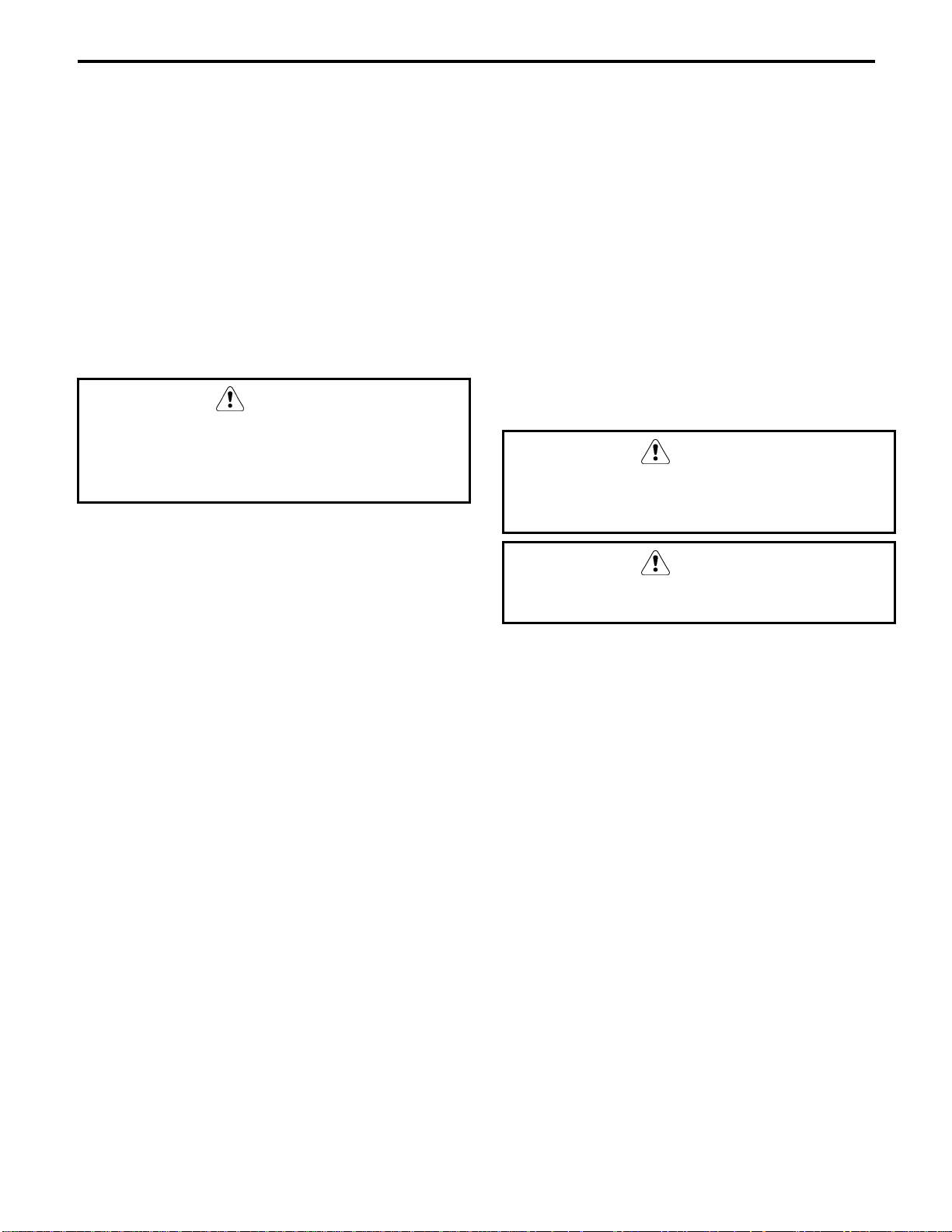
CLEANING THE FAN BLADES AND
MOTOR
If necessary, clean the fan blades and motor with
a soft cloth. If it is necessary to wash the fan
blades, cover the fan motor to prevent moisture
damage.
Section 4 Maintenance
Component Replacement Procedures
WARNING
Disconnect electric power before performing
any service.
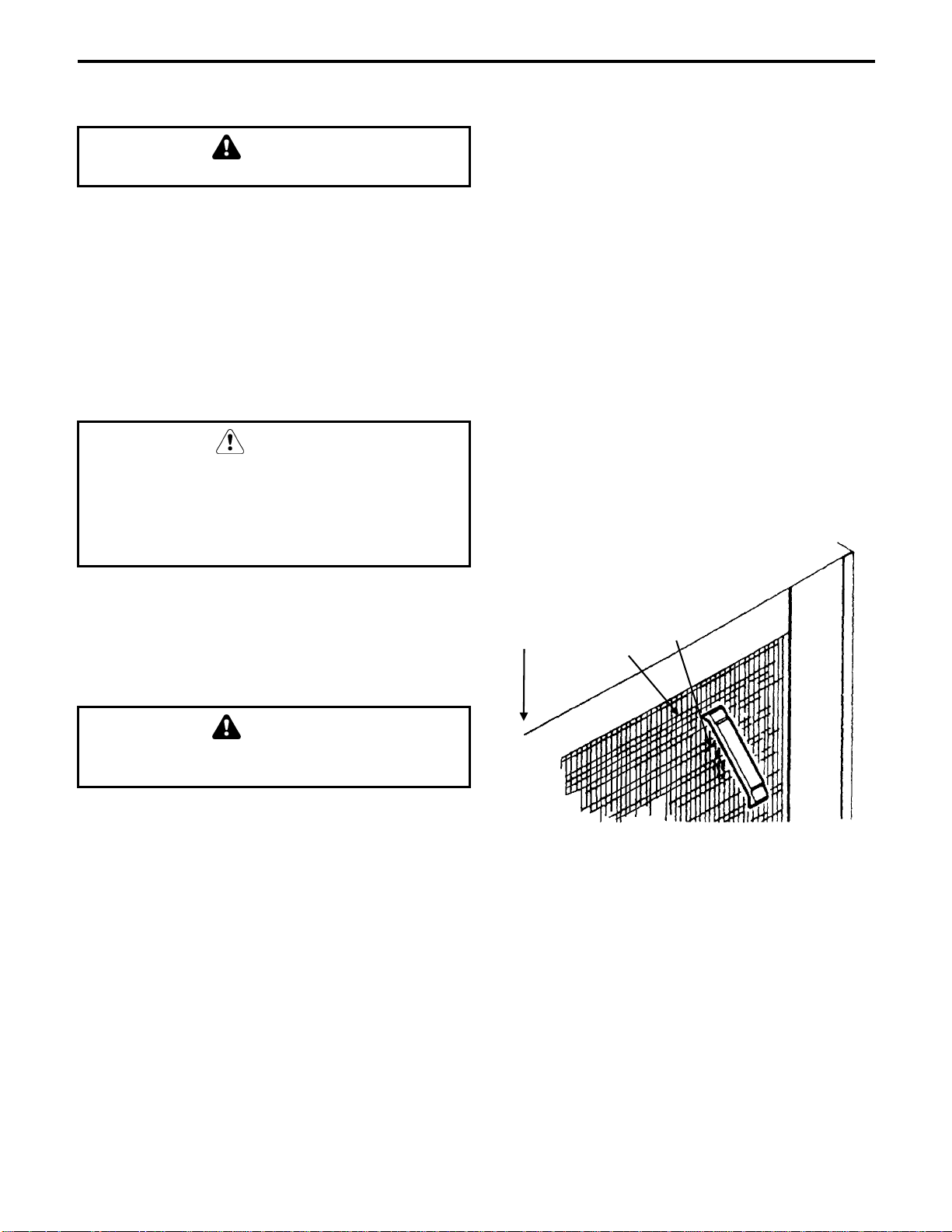
EVAPORATOR FAN MOTOR
1 Section Refrigerators and Freezers
If Mounting Bracket Is Not Broken
1. Remove Windrunner air distribution duct
from the cabinet interior ceiling
(Figure 4-1).
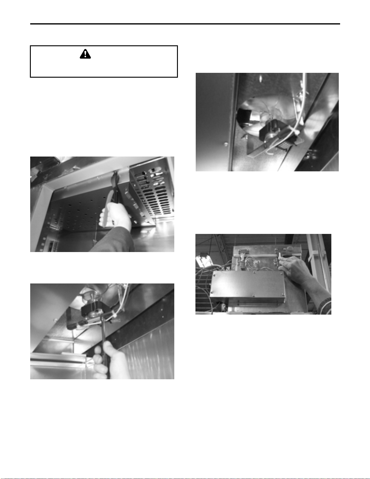
3. Using a 1/4" nut driver, remove the (2) motor
mounting screws and separate the motor
from the bracket (Figure 4-3).
Figure 4-3
4. Reverse steps 1-3 to replace motor.
Figure 4-1
2. Disconnect the (2) terminal connectors from
the motor (Figure 4-2).
5. Reconnect power and return to normal use.
NOTE: The evaporator-housing lid may be
removed to provide added lighting and visibility
(Figure 4-4).
Figure 4-4
Figure 4-2
4-3
Maintenance Section 4
EVAPORATOR FAN MOTOR
3. Using a 1/4" nut driver, remove the (2) motor
1 Section Refrigerators and Freezers
If Mounting Bracket Is Broken
mounting screws and separate the motor
from the bracket (Figure 4-7).
1. Remove the Windrunner air distribution duct
from the interior ceiling (
Figure 4-5).
Figure 4-7
4. Remove the evaporator-housing lid, located
Figure 4-5
on the cabinet top (Figure 4-8).
2. Disconnect the (2) terminal connectors from
the motor (Figure 4-6).
Figure 4-6
Figure 4-8
5. Remove the coil mounting screws and
carefully lift the coil, only enough to gain
access to the motor mounting screws
(Figure 4-9).
Continued next page…
4-4
Section 4 Maintenance
Figure 4-9
6. When the coil has been moved, remove the
Figure 4-11
evaporator drain pan by removing (4)mounting screws.
7. Remove the bracket mounting screws and
replace bracket-motor assembly.
8. Reverse Steps 1-5 to complete motor
installation.
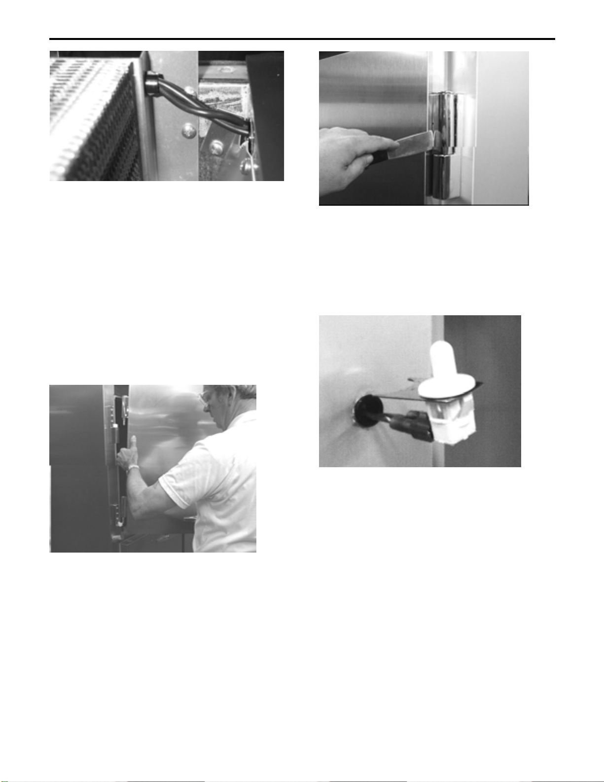
3. Remove the (3) hinge mounting screws and
carefully pull the hinge flange from the
cabinet front.
4. Slide the light switch and switch retainer
from the hinge. Unplug the switch
Figure 4-12).
(
9. Reconnect power and return to normal use.
LIGHT SWITCH
1. Remove the door by lifting straight up
(Figure 4-10). Carefully set the door aside.
Figure 4-10
2. Pry off the TOP hinge cover on the cabinet
hinge flange with a flat blade screwdriver or
flat scraper (Figure 4-11).
Figure 4-12
5. Install the new switch into the hinge and
replace the door hinge onto the cabinet front.
Install the (3) mounting screws. Snug the
screws but DO NOT tighten fully.
6. Re-hang the door onto the hinges.
7. Make sure that the door is hanging plumb
and that the door operates properly.
8. Tighten the screws and replace the hinge
cover.
4-5
 Loading...