

MCC 50-2104, T50-2112 Service Manual
T-367 Manual
OPERATION/SERVICE MANUAL
© 2015 Mobile Climate Control
for
MCC Eco Xcel SERIES
T-367
REV. 05/2015

TABLE OF CONTENTS
SAFETY SUMMARY Safety--1.......................................................................
DESCRIPTION 1--1...............................................................................
1.1 INTRODUCTION 1--1.....................................................................
1.2 GENERAL DESCRIPTION 1--2.............................................................
1.2.1 Rooftop Unit 1--2......................................................................
1.2.2 Condensing Section 1--2...............................................................
1.2.3 Evaporator Sections 1--3...............................................................
1.2.4 MCC Microprocessor 1--3..............................................................
1.3 REFRIGERATION SYST EM COMPONENT SPECIFICATIONS 1-- 3.............................
1.4 ELECTRICAL SPECIFICATIONS -- MOTORS 1-- 3............................................
1.5 SAFETY DEVICES 1--4...................................................................
1.6 AIR CONDITIONING REFRIGERATION CYCLE 1--5..........................................
1.7 HEATING CYCLE 1--5....................................................................
OPERATION of MCC XCEL DRIVER DISPLAY 2--1...................................................
2.1 General Description 2--1...................................................................
2.2 STARTING, STOPPING AND OPERATING INSTRUCTIONS 2--1..............................
2.2.1 Starting 2--1..........................................................................
2.3 SEQUENCE OF OPERATION 2-- 2..........................................................
2.3.1 Function of Keys when “Engine On” and controller active: 2--2...............................
2.4 BASIC OPERATING INSTRUCTIONS 2--3..................................................
2.4.1 Display 2--3..........................................................................
2.4.2 Interior Set Point Temperature Control 2--3...............................................
2.4.3 Blower Speed Setting 2--3..............................................................
2.4.4 Mode Selection Descriptions 2--3........................................................
2.4.5 Capacity Control “Ladder” Diagrams 2--3.................................................
2.4.6 Display Settings 2--5...................................................................
2.4.7 HVAC Information Screens 2--6.........................................................
2.4.8 HVAC Diagnostics Screens 2--7.........................................................
2.4.9 HVAC Alarm Description 2--8...........................................................
2.5 MCC Eco NG Coolview 2-- 9...............................................................
2.5.1 Starting the MCC Coolview Application 2--10...............................................
2.5.2 Coolview Screen Layout 2--11...........................................................
2.5.3 Eco NG Display Pin out Description 2--16..................................................
2.5.4 Eco NG Controller Pin out Description 2--17...............................................
TROUBLESHOOTING 3--1.........................................................................
3.1 System Will Not Cool 3--1..............................................................
3.2 System Runs But Has Insufficient Cooling 3--1............................................
3.3 Abnormal Pressures 3--1...............................................................
3.4 Abnormal Noise Or Vibrations 3--1.......................................................
3.5 No Evaporator Air Flow Or Restricted Air Flow 3--2........................................
3.6 Expansion Valve Malfunction 3--2........................................................
3.7 Heating Malfunction 3--2...............................................................
SERVICE 4-1....................................................................................
4.1 MAINTENANCE SCHEDULE 4-1...........................................................
© 2015 Mobile Climate Control
1
T-367Rev . 05/2015

4.2 OPENING TOP COVER (EVAPORATORS) 4-2..............................................
4.3 REMOVING TOP COVERS (CONDENSER) 4-2.............................................
4.4 SUCTION AND DISCHARGE SERVICE VALVES 4-3.........................................
4.4.1 Installing R--134a Manifold Guage Set 4-4...............................................
4.4.2 SYSTEM PUMP DOWN FOR LOW SIDE REPAIR 4-6....................................
4.4.3. Removing Entire System Charge 4-7....................................................
4.5 REFRIGERANT LEAK CHECK 4-7.........................................................
4.6 EVACUATION AND DEHYDRATION 4-7....................................................
4.6.1 General 4-7..........................................................................
4.6.2 Preparation 4-7.......................................................................
4.6.3 Procedure for Evacuation and Dehydrating System (One Time Evacuation) 4-8...............
4.6.4 Procedure for Evacuation and Dehydrating System (Triple Evacuation) 4-8...................
4.7 CHECKING AND ADDING REFRIGERANT TO SYSTEM 4-8..................................
4.7.1 Checking Refrigerant Charge By Pressures 4-8...........................................
4.7.2 Checking Refrigerant Charge By Receiver Sight Glasses 4-9...............................
4.7.3 Adding Full Charge 4-9................................................................
4.7.4 Adding Partial Charge 4-11.............................................................
4.8 CHECKING SYSTEM FOR NON--CONDENSIBLES 4-11.......................................
4.9 CHECKING AND REPLACING HIGH OR LOW PRESSURE SWITCH 4-11.......................
4.10 FILTER--DRIER 4-12......................................................................
4.10.1 To Check Filter--Drier 4-12...............................................................
4.10.2 T o Replace Filter--Drier 4-12.............................................................
4.11 SERVICING THE LIQUID LINE SERVICE VALVE 4-12.........................................
4.11.1 Coil Replacement 4-13.................................................................
4.11.2 Internal Part Replacement 4-13..........................................................
4.11.3 Replace Entire LLS Valve 4-13...........................................................
4.12 THERMOSTATIC EXPANSION VALVE 4-14..................................................
4.12.1 Valve Replacement 4-14................................................................
4.12.2 Superheat Measurement 4-14...........................................................
4.13 REPLACING EVAPORATOR RETURN AIR FILTERS 4-15.....................................
4.14 COMPRESSOR MAINTENANCE 4-16.......................................................
4.14.1 Shaft Seal Reservoir 4-16...............................................................
4.14.2 Refrigerant Removal From An Inoperative Compressor. 4-16................................
4.14.3 Pump Down An Operable Compressor For Repair 4-16.....................................
4.14.4 Removing the Compressor 4-17.........................................................
4.14.5 Transferring Compressor Clutch 4-18.....................................................
4.14.6 Compressor Oil Level 4-19..............................................................
4.14.7 Checking Unloader Operation 4-19.......................................................
4.15 TEMPERATURE SENSOR CHECKOUT 4-21.................................................
4.16 PRESSURE TRANSDUCER CHECKOUT 4-21...............................................
4.17 REPLACING SENSORS AND TRANSDUCERS 4-21..........................................
ELECTRICAL 5--1................................................................................
5.1 INTRODUCTION 5--1.....................................................................
© 2015 Mobile Climate Control
2
T-367Rev . 05/2015

LIST OF TABLES
Table 1-- 1 Models 1--1.............................................................................
Table 1-- 2 Additional Support Manuals 1--1............................................................
Table 3-- 1 General System Troubleshooting Procedures 3--1............................................
Table 4-1 Temperature Sensor Resistance 4-21........................................................
Table 4-2 Pressure Transducer Voltage 4-22...........................................................
Table 4-3 R--134a Temperature -- Pressure Chart 4-23..................................................
LIST OF FIGURES
Figure1--1RooftopUnit(EcoXcel) 1--2.............................................................
Figure 1--2 Refrigerant Flow Diagram 1--6...........................................................
Figure 1--3 Heat Flow Diagram 1--7.................................................................
Figure 2-1 Driver Display Module-- Control Layout 2--1................................................
Figure 2-2 Driver Display Module-- Display Layout 2--2................................................
Figure 2-3 Capacity Control Ladder Diagrams 2--4....................................................
Figure 2-4 HVAC DISPLAY SETTINGS 2--5..........................................................
Figure 2-5 HVAC INFORMATION SCREENS 2--6....................................................
Figure 2-6 HVAC DIAGNOSTIC SCREENS 2--7......................................................
Figure 2-7 MCC Eco NG Display Alarms 2--8........................................................
Figure 2-8 MCC Eco NG Coolview (Example Screenshot) 2--9.........................................
Figure 2-9 MCC Eco NG Coolview (VIEW Tab) 2--10...................................................
Figure 2-10 MCC Eco NG Coolview Inputs and Mode (VIEW Tab) 2--11..................................
Figure 2-11 MCC Eco NG Coolview Outputs (VIEW Tab) 2--12..........................................
Figure 2-12 MCC Eco NG Coolview Error List (ERROR Tab) 2--12.......................................
Figure 2-13 MCC Eco NG Coolview Statistics (HOURS Tab) 2-- 13.......................................
Figure 2-14 MCC Eco NG Coolview Simulation Mode 2--14.............................................
Figure 2-15 MCC Eco NG Coolview Data Logger 2--15.................................................
Figure 2-16 MCC Eco NG Display Pinout 2--16........................................................
Figure 2-17 MCC Eco NG ControllerPinout 2--17......................................................
Figure 4-1 Opening Top Cover (Evaporator) 4-2......................................................
Figure 4-2 Removing Top Covers (Condenser) 4-2...................................................
Figure 4-3 Suction or Discharge Service Valve 4-3...................................................
Figure 4-4 Manifold Gauge Set (R--134a) 4-4........................................................
Figure 4-5 Service Connections 4-5................................................................
Figure 4-6 Rule of Thumb 4-8.....................................................................
Figure 4-7 Service Connections 4-10................................................................
Figure 4-8 Checking High Pressure Switch 4-11.......................................................
Figure 4-9 Filter--Drier Removal 4-12................................................................
Figure 4-10 Liquid Line Solenoid Valve 4-13..........................................................
Figure 4-11 Thermostatic Expansion Valve Bulb and Thermocouple 4-14.................................
Figure 4-12. Compressor Service Connections 4-16...................................................
Figure 4-13. Compressor Service Connections 4-16...................................................
Figure 4-14. Compressors 4-17.....................................................................
© 2015 Mobile Climate Control
3
T-367Rev . 05/2015

LIST OF FIGURES (Continued)
Figure 4-15. Removing Bypass Piston Plug 4-17......................................................
Figure 4-16. Compressor Clutch 4-18................................................................
Figure 4-17 Transducer Terminal Location 4-21.......................................................
Figure 5--1 Schematic 50--2104S 5--2...............................................................
Figure 5--2 Schematic T50--21 12S 5--3..............................................................
© 2015 Mobile Climate Control
4
T-367Rev . 05/2015

SAFETY SUMMARY
GENERAL SAFETY NOTICES
The following generalsafety notices supplement the specific warnings and cautions appearing elsewhere in
this manual. They are recommended precautions that must be understood and applied during operation
and maintenanceof the equipment covered herein. A listingof the specificwarningsand cautions appearing
elsewhere in the manual follows the general safety notices.
FIRST AID
An injury, no matter how slight, should never go unattended. Always obtain first aid or medical attention
immediately.
OPERATING PRECAUTIONS
Always wear safety glasses.
Keep hands, clothing and tools clear of the evaporator and condenser fans.
No work should be performed on the unit until all start-stop switches are placed in the OFF position, and
power supply is disconnected.
Always work in pairs. Never work on the equipment alone.
In case of severe vibration or unusual noise, stop the unit and investigate.
MAINTENANCE PRECAUTIONS
Beware of unannounced starting of the evaporator and condenser fans. Do not open the unit cover before
turning power off.
Be sure power is turned off before working on motors, controllers, solenoid valves and electrical controls.
Tag circuit breaker and power supply to prevent accidental energizing of circuit.
Do not bypass any electrical safety devices, e.g. bridging an overload, or using any sort of jumper wires.
Problems with the system should be diagnosed, and any necessary repairs performed by qualified service
personnel.
When performing any arc welding on the unit, disconnect all wire harness connectors from the modules in
the control box. Do not remove wire harness from the modules unless you are grounded to the unit frame
with a static-safe wrist strap.
In case of electrical fire, open circuit switch and extinguish with CO2(never use water).
© 2015 Mobile Climate Control
Safety--1
T-367 Rev. 05/2015
SPECIFIC WARNINGS AND CAUTIONS
WARNING
Use of an electro-magnetic valve as a means of positive shutoff for service is not recom
mended for safety, or good service practice.
WARNING
Be sure to observe warnings listed in the safety summary in the front of this manual be
fore performing maintenance on the hvac system
WARNING
Read the entire procedure before beginning work. Park the vehicle on a level surface,
with parking brake applied. Turn main electrical disconnect switch to the off position.
WARNING
Do Not Use A Nitrogen Cylinder Without A Pressure Regulator
WARNING
Do Not Use Oxygen In Or Near A Refrigeration System As An Explosion May Occur.
WARNING
The Filter-drier May Contain Liquid Refrigerant. Slowly Loosen The Connecting Nuts And Avoid Con
tact With Exposed Skin Or Eyes.
CAUTION
The 50-2104 Rooftop Systems have R134a service port couplings installed on the compressor and on the unit
piping.
CAUTION
To prevent trapping liquid refrigerant in the manifold gauge set be sure set is brought to suction pres
sure before disconnecting.
© 2015 Mobile Climate Control
Safety--2
T-367 Rev. 05/2015
SECTION 1
DESCRIPTION
1.1 INTRODUCTION
This manual contains Operating Instructions,
Service Instructions and Electrical Data for the
EcoXcel Model Air Conditioning and Heating
equipment furnished by Mobile Climate Control as
showninTable1-1.
The system is identified with a Model/Serial number
tag located inside the evaporator section, on the rear
bulkhead wall of the assembly. Example is shown in
Figure 1-1.
Models consists of a Rooftop unit containing the
condensing section, the evaporator sections and
Table 1-1 Models
Model
50-2104 24 VDC
T50-2112 24 VDC
Voltage Controller With Heat Single Loop W/Covers
MCC EcoTemp NG
Microprocessor
MCC EcoTemp NG
Microprocessor
engine compartment mounted compressor. To
complete the system, the air conditioning and
heating equipment interfaces, electrical cabling,
refrigerant piping, engine coolant piping (for
heating), duct work and other components
furnishedby Mobile Climate Control and/or the bus
manufacturer.
Additional support manuals are shown in Table 1-2.
Operation of the unit is controlled automatically by a
Mobile Climate Control Microprocessor based
controller. The controls maintain the vehicle's
interior temperature at the desired set point.
Yes X X
Yes X X
Table 1-2 Additional Support Manuals
MANUAL NUMBER
T-367PL Eco Xcel Models Service Replacement Parts List
EQUIPMENT COVERED TYPE OF MANUAL
© 2015 Mobile Climate Control
1--1
T-367Rev. 05/2015
1.2 GENERAL DESCRIPTION
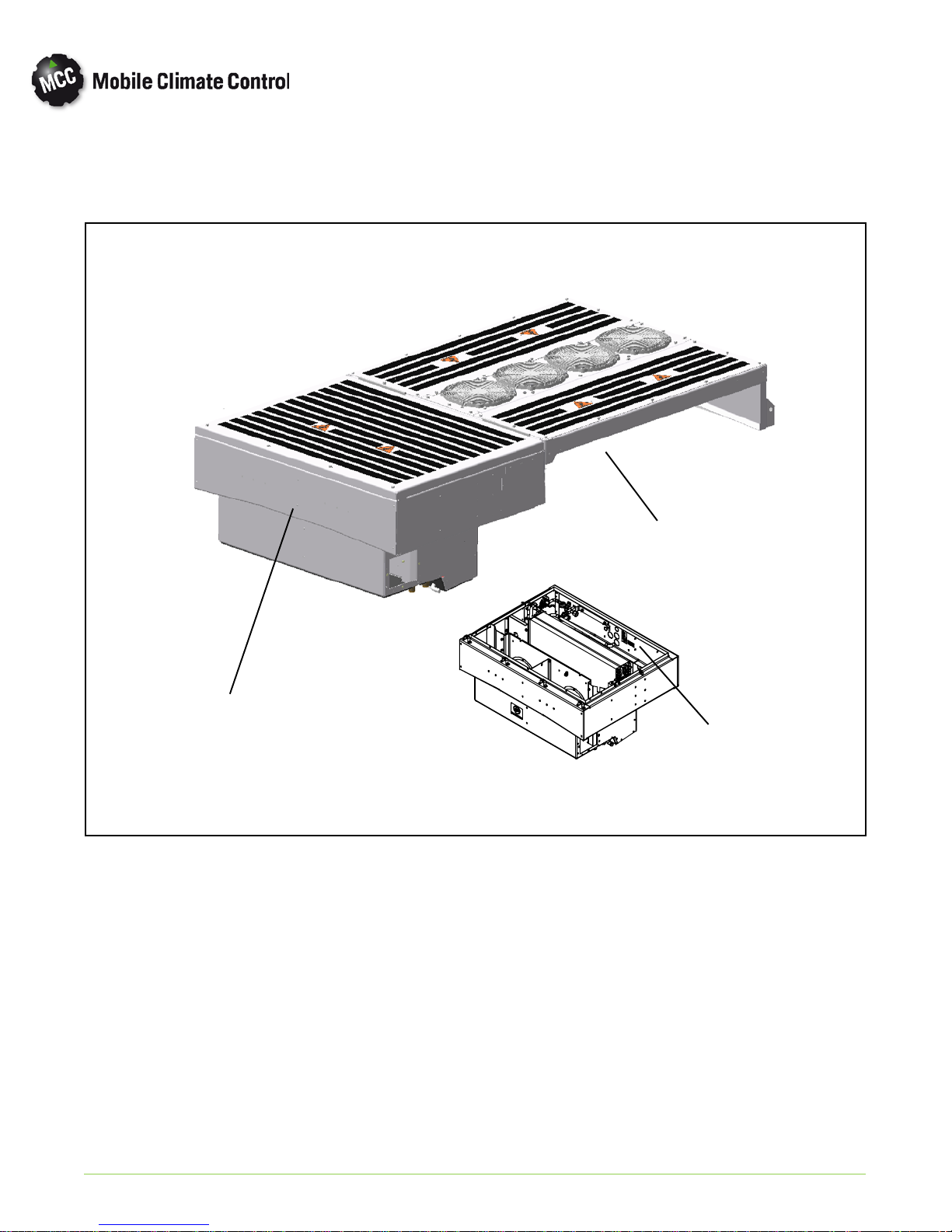
1.2.1 Rooftop Unit
The rooftop unit includes the condenser section and the evaporator sections (See Figure 1-1).
Condenser Section
Evaporator Section
Figure 1-1 Rooftop Unit (Eco Xcel)
1.2.2 Condensing Section
The condensing section includes 2 micro-channel
condenser coils, four (4) fan and motor assemblies
and receiver tank assembly with sight glasses,
moisture indicator and fusible plug
The condenser coils provideheat transfer surface for
condensing refrigerant gas at a high temperature and
pressure into a liquid at high temperature and
pressure. The condenser fans circulate ambient air
across the outside of the condenser tubes at a
temperature lower than refrigerant circulating inside
the tubes; this results in condensation of the
refrigerant into a liquid. The receiver tank is also
EVAPORATOR SECTION
Interior Location
Model/Serial Number Plate
equipped with a pressure relief valve (fusible plug)
which protects the system from unsafe high pressure
conditions. The filter-drier,located in the evaporator
section,removes moisture and debris from the liquid
refrigerant before it enters the thermostatic
expansion valve in the evaporator assembly.
a. Condenser fan operation
Low Speed ON: 150 psig (10.31 bar)
Low Speed OFF: 120 psig (8.27 bar)
High Speed ON: 225 psig (15.51 bar)
High Speed OFF: 165 psig (11.38 bar)
© 2015 Mobile Climate Control T-367Rev. 05/2015
1--2
1.2.3 Evaporator Sections
The evaporator section includes the evaporator coil,
two (2) blower motor assemblies, thermostatic
expansion valve, heater coil assembly, heater valve,
filter/drier, service valves and condensate drain
connections.
The evaporator coil provides heat transfer surface
for transferring heat from air circulating over the
outside of the coil to refrigerant circulating inside the
tubes; thus providing cooling. The heating coils
provide a heat transfer surface for transferring heat
from engine coolant water circulating inside the
tubes to air circulatingover the outside surface of the
tubes, thus providing heating. The fans circulate the
air over the coils. The air filters (OEM supplied)
remove dirt particles from the air before it passes
over the coils. The thermostatic expansion valve
meters the flow o f refrigerant entering the
evaporator coils. The heat valve controls the flow of
engine coolant t o the heating coils upon receipt of a
signal from the controller. The condensate drain
connections provide a means for connecting tubing
for disposing of con densate collected on the
evaporator coils during cooling operation.
1.2.4 MCC Microprocessor
The MCC controller maintains desired temperature
set point by controlling compressor capacity, fan
speeds and heat valve operation. Refer to Section 2,
for operational sequences.
1.3 REFRIGERATION SYSTEM COMPONENT SPECIFICATIONS
a.System Capacity: Cooling - 120,000 Btu/Hr (35 kW)
Heating - 126,000 Btu/Hr (37 kW)
b. Refrigerant Charge R-134a (Approximate)
NOTE
Refrigerant charge will depend on hose
lengths and diameters; or if there is an InDash unit (front evaporator). The following
should only be used as a guideline.
c. Compressor
Compressor
No. Of Cylinders 6
Weight, (Dry) With Clutch 145 Lbs. (66 kg)
Oil Charge
d. Thermostatic Expansion Valve:
7 Ton Capacity- Adjustable
e. High Pressure Switch (HPS)
Opens at: 360 ±10 psig (24.82 ±0.68bar)
Closes at: 285 ±15 psig (19.65 ±0.68bar)
f. Low Pressure Switch (LPS)
Opens at: 6 ±3psig (0.41 ±0.20 bar)
Closes at: 25 ±3psig(1.7±0.20 bar)
g. Water Temperature Switch (WTS) (If Equipped)
[Bus Manufacturer Supplied - Suggested close on tempera
ture rise at 105°F(41°C)]
Normally Closed
Normally Open
05G
5.5 pints
(2.6 liters)
1.4 ELECTRICAL SPECIFICATIONS - MOTORS
a. Evaporator Blower/Motor
Evaporator Motor
Full Load Amps (FLA) ~25
Bearing L ubrication
b. Condenser Fan Motor
Condenser Motor
Full Load Amps (FLA) ~7
Bearing L ubrication
c. Temperature Sensors (All)
Input Range: -40 to 167° F(-40to75°C)
Output: NTC 10K ohms at 77° F(25°C)
d. Ambient Sensor (Controls Compressor Outputs)
Brushless
24 VDC
Factory Lubricated
(additional grease not required)
Brushless
24 VDC
Factory Lubricated
(additional grease not required)
50-2104 with 05G Compressor
13 ± 0.5 Pounds (5.9 ± 0.23 kg)
© 2015 Mobile Climate Control
1--3
Opens at: 43° F(6.1°C)
Closes at: 47° F(8.3°C)
T-367Rev. 05/2015

1.5 SAFETY DEVICES
System components are protected from damage
caused by unsafe operating conditions with safety
devices. Safety devices with Mo b ile Climate Contro l
supplied equipment include high pressure switch
(HPS), low pressure switch (LPS), fusible plug,
circuit breakers and fuses.
a. Pressure Switches
High Pressure Switch (HPS)
During the air conditioning cycle, compressor clutch
operation will automatically stop if the HPS switch
contacts open due to an unsafe operating condition.
Opening HPS contacts de-energizes the compressor
clutch shutting down the compressor. The high
pressure switch (HPS) is installed at the compressor
assembly. See paragraph 1.3 for specifications.
Low Pressure Switch (LPS)
The low pressure switch is installed on the
compressor assembly and opens on a pressure drop
to shut down the system when a low p ressure
condition occurs. See paragraph 1.3 for
specifications.
Defrost Mode
Opens Compressor Output at: 28° F(-2.2°C)
Closes Compressor Output at: 32° F(0°C)
The ambient tem p erature sensor measures the
condenser inlet air temperature. These settings
protect the compressor from damage caused by
operation at low pressures.
d. Unloader Operation
The compressor is equipped with two unloaders to
allow compressor operation at 33%, 66% or 100%
capacity.
Low Pressure Control
Energizes Unloader Output 1 (Unloads) at: 25 psig (1.7
bars)
De-energizes Unloader Output1 (Loads) at: 32 psig (2.2
bars)
Energizes Unloader Output 2 (Unloads) at: 21 psig (1.4
bars)
De-energizes Unloader Output1 (Loads) at: 28 psig (1.9
bars)
b. Fuses and Circuit Breakers
The Relay Bo ard is protected against high current by
an OEM supplied circuit breaker or fuse located in
the bus battery compartment (100 Amp for 24 VDC
systems is recommended). Independent fuses and
circuit breakers protect electrical circuits from high
current conditions. During a high current condition,
the circuit protection may open.
c. Ambient Lockout
Auto Mode
Opens Compressor Output at: 43° F(6.1°C)
Closes Compressor Output at: 47° F(8.3°C)
High Pressure Control (below 87 F (30.8C)
Energizes Unloader Output (Unloads) at: 300 psig (20.7
bars)
High Pressure Control (above 92 F (33.6C)
Energizes Unloader Output (Unloads) at: 320 psig (23.4
bars)
In response to the high pressure conditions
above, the unloader remains energized for 2
minutes. Once the pressures return below the
parameters listed, the unloader circuit will de-en
ergize.
© 2015 Mobile Climate Control T-367Rev. 05/2015
1--4

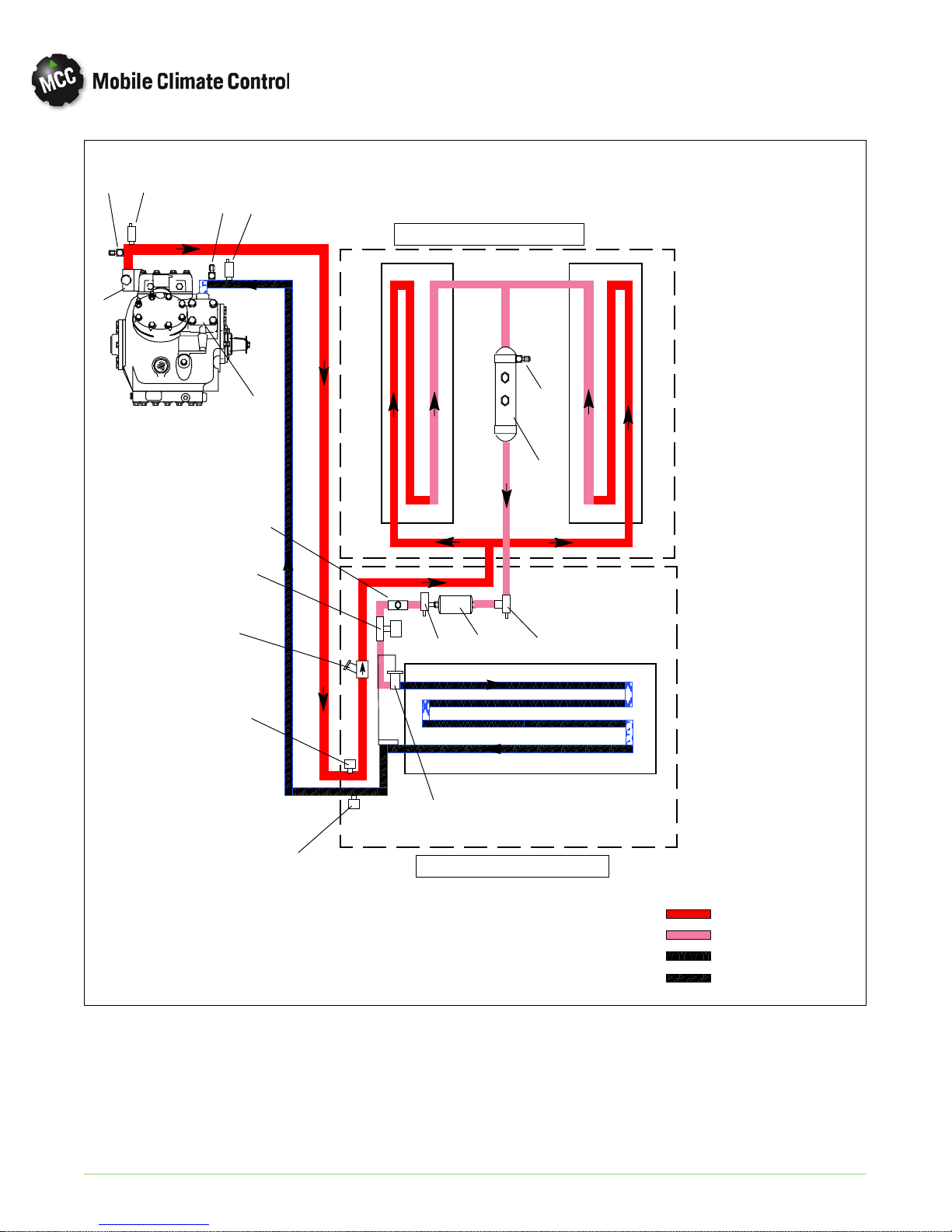
1.6 AIR CONDITIONING REFRIGERATION CYCLE
When air conditioning (cooling) is selected by the
controller, the unit operates as a vapor compression
system using R-134a as a refrigerant (See Figure 1-2
refrigerant flow diagram). The main components of
the system are the A/C compressor, air-cooled
condenser coils, filter-drier, thermostatic expansion
valve, liquid line solenoid valve and evaporator coils.
The compressor raises the pressure and the
temperature of the refrigerant and forces it into the
condenser tubes. The condenser fan circulates
surrounding air (which is at a temperature lower than
the refrigerant) over the outside of the condenser
tubes. Heat transfer is established from the
refrigerant (inside the tubes) to the condenser air
(flowing over the tubes). The condenser tubes have
fins designed to improve the transfer of heat from
the refrigerant gas to the air; this removal of heat
causes the refrigerant to liquefy, thus liquid
refrigerant leaves the condenser and flows to the
filter-drier.
The refrigerant passes through a filter-drier where a
desiccant keeps the refrigerant clean and dry.
From the filter-drier,the liquid refrigerantthen flows
through the liquid line to the sight-glass and then to
the thermostatic expansion valve. The thermal
expansion valvereduces pressure and temperature of
the liquid and meters the flow of liquid refrigerant to
the evaporator to obtain maximum use of the
evaporator heat transfer surface.
The low pressure, low temperature liquid that flows
into the evaporator tubes is colder than the air that is
circulated over the evaporator tubes by the
evaporatorfans. Heat transferis established from the
evaporator air (flowing over the tubes) to the
refrigerant (flowing inside the tubes). The
evaporator tubes have aluminum fins to increase
heat transfer from the air to the refrigerant;therefore
the cooler air is circulated to the interior of the bus.
The transfer of heat from the air to the low
temperature liquid refrigerant in the evaporator
causes the liquid to vaporize. This low temperature,
low pressure vapor passes through the suction line
and returns to the compressor where the cycle
repeats.
1.7 HEATING CYCLE
Heating circuit (See Figure 1-3) components
furnished by Mobile Climate Control include the
heater cores and solenoid operated heat valve.
Components furnished by the bus manufacturer
may include a water temperature switch (WTS),
boost water pump and floor blower convectors.
The controller automatically controls the heat valves
during the heating mode to maintain required
temperatures inside the bus. Engine coolant (glycol
solution) is circulated through the heating circuit by
the engine and an auxiliary boost water pump. When
the heat valve solenoids are energized, the valves will
open to allow engine coolant to flow through the
heater coils. The valves are normally closed.
NOTE: In order to ensure water is entering the
heater coils sufficiently heated, it is suggested that the
OEM supplied Water Temperature Switch (WTS),
(If equipped) close on temperature rise at 105°F
(40.5°C).
© 2015 Mobile Climate Control
1--5
T-367Rev. 05/2015
1
6
2
7
CONDENSER SECTION
3
4
10
14
5
11
13
12
9
16
15
12
8
1. High Pressure Switch
2. Low Pressure Switch
3. Discharge Service Valve
4. Suction Service Valve
5. Discharge Check Valve
6. Service Port, (High Side)
7. Service Port, (Low Side)
8. Pressure Transducer (SPT)
© 2015 Mobile Climate Control T-367Rev. 05/2015
EVAPORATOR SECTION
9. Thermal Expansion Valve (TXV)
10. Liquid Line Sight Glass
11. Pressure Transducer (DPT)
12. Filter Drier Service Valve
13. Filter Drier
14. Liquid Li ne Solenoid Valve
15. Receiver Tank
16. Fusible Plug
Figure 1-2 Refrigerant Flow Diagram
1--6
HT HP SHV
HT HP SCL
LT LP SM
LT LP SHV
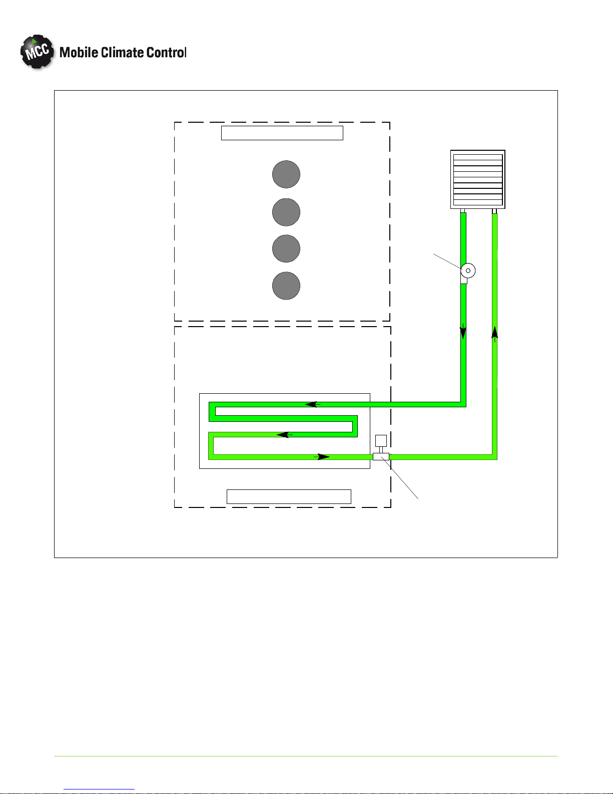
CONDENSER SECTION
MAIN ENGINE
RADIATOR
Boost
Pump
INLET
EVAPORATOR SECTION
Figure 1-3 Heat Flow Diagram
OUTLET
Heat Valve
(N.C.)
© 2015 Mobile Climate Control
1--7
T-367Rev. 05/2015

SECTION 2
OPERATION of MCC EcoXcel DRIVER DISPLAY
2.1 General Description
Operation of the MCC Eco Xcel unit is controlled
through the MCC Driver's display.
When the MCC Displayis used to control operation,
the Mode selection is selected using the “Mode”
button ( item 3) on display, shown in Figure 2-1.
Ability to view system pressures, sensor
temperatures, component status, etc. is available
Through the MCC Display Module.
2.2 STARTING, STOPPING AND OPERATING INSTRUCTIONS
The MCC Drivers Display Module is marked with
international symbols (See Figure 2-1).
Before starting, electrical power must be available
from the bus power supply.
A circuit b reaker/fuse in the battery com partment
passes power for the clutch, evaporator and
condenser assemblies.
2.2.1 Starting
a. If the engine is not running, start the engine.
b. When the 24VDC power is applied, the driver dis
play will be ready to except req u est for system op
eration. Press the On/Off key (Item 1, Figure 2-1)
on the displayto triggerthe start up sequence, con
trolled by the MCC D rivers display module.
2.2.2 Stopping
Toggling the On/Off key (Item 1, Figure 2-1) on the
display again will stop the system operation
controlled by the MCC D rivers display module.
2
1
5
Figure 2-1 Driver Display Module- Control Layout
© 2015 Mobile Climate Control
1. On/Off
2. Temperature Set Point Control
3. Cursor and Mode Selection
4. Information/Display Settings
5. Alarm Indicator
2--1
3
4
T-367Re v. 05/2015
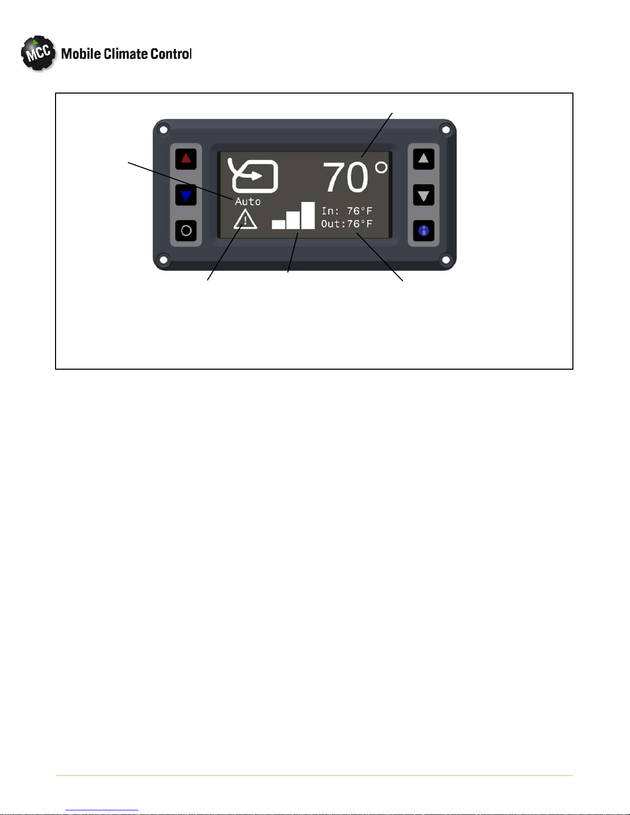
2
1
5
3
1. Operation Mode
2. Temperature Set Point
3. Fan Speed Indicator
4. Interior/Exterior Temperatures
5.. Alarm Indicator Symbol
Figure 2-2 Driver Display Module- Display Layout
2.3 SEQUENCE OF OPERATION
2.3.1 Function of Keys when “Engine On” and controller
active:
a. On/Off Key - Turns HVAC unit On or Off, un
less OEM supplied switches are installed. It also is
used to exit diagnostic men u .
b. Temperature Set Point Control Keys -These
buttons increase or decrease the tem perature set
point for the passenger area HVAC unit.
c. Cursor/Mode Selection Key- Used to toggle
through parameter settings in diagnostic mode or
set the operating mode to Auto, Heat, Vent, Cool,
and Defrost in normal display mode.
4
d. Information/Display Settings Key - Allows ac
cess to display settings and system diagnostics.
2.3.2 Illuminating Indications (Display)
With “Engine-On” and Controller active by the
On/Off button.
NOTE:
Depending on Customer specification, the
modes of operation may be controlled
strictly through manual switches provided in
the driver's area.
© 2015 Mobile Climate Control
2--2
T-367Rev05/2015

2.4 BASIC OPERATING INSTRUCTIONS
When the engine is running, press the On/Off
buttonondisplay.
2.4.1 Display
When the unit is ON, the display shows the interior
set point temperature, current blower speed setting,
mode selection and Interior/Exterior temperatures.
2.4.2 Interior Set Point Temperature Control
Press the UP (Red) or Do wn (Blue) keys to set the
desired interior temperature.
The t em perature can be adjusted between 62° F(16°
C) and 82° F(28° C).
2.4.3 Blower Speed Setting
Blower speed operation will be set for high or low
speed operation automatically through software, or
can be set through manual switches provided at the
driver area.
2.4.4 Mode Selection Descriptions
a. Auto - In the auto mode, the ECC node willadjust
the individual components to maintain the desired
set point temperature.
In the auto mode, the evaporator fans will operate
in an “Ultra” high speed to achieve desired set
point faster, when the interior temperature is
greater than 5.4°F (3°C), from desired set point.
In the auto mode, the A/C system will continue to
operate when set point is reached, and will ener
gize the boost pump and de-energize the heat
solenoid valve to maintain temperature. This is re
ferred to as Reheat mode, to provide additionalde
humidification of interior space.
The reheat mode will be disabledif the outsideam
bient air temperature is below 43° F(6.1° C).
b. Cooling - In the cooling mode, the Compressor,
condenser fans and evaporator fans will be ener
gized. The heater solenoid valve will be energized
(closed), to provide full cooling.
The compressor and condenser fans will be de-en
ergized 2 degrees F below set point. The evaporat
or fans willcontinue to operateto circulateinterior
air.
c. Heating - In the heating mode, the compressor
and condenser fans will remain de-energized.
Evaporator fans will be energized. The boost
pump willbe energized,andthe heat solenoidvalve
will be de-energized (opened), to allow engine
coolant to flow through the heater coils. If the in
terior temperature is more than 5° F(3° C) below
set point, the floor blowers (if equipped) will also
be energized.
d. Defrost - In the defrost mode, the boost pump
will be energized to pro vide engine coolant flow to
the drivers unit to allow defogging of the wind
shield.
Defrost Override - In the event the main HVAC
system is “OFF”, the ability of the OEM to
provide a signal to the controller to energize the
Boost Pump to provide engine coolant flow for
the Drivers Defroster is provided.
e. Vent- In the vent mode, the evaporator blowers
are operated to circulate air in the bus.
2.4.5 Capacity Control “Ladder” Diagrams
Ladder diagrams showing system operational
control logic for Auto/ Cool (Reheat system), and
Heat, can be seen in Figure 2-3.
© 2015 Mobile Climate Control
2--3
T-367Re v. 05/2015
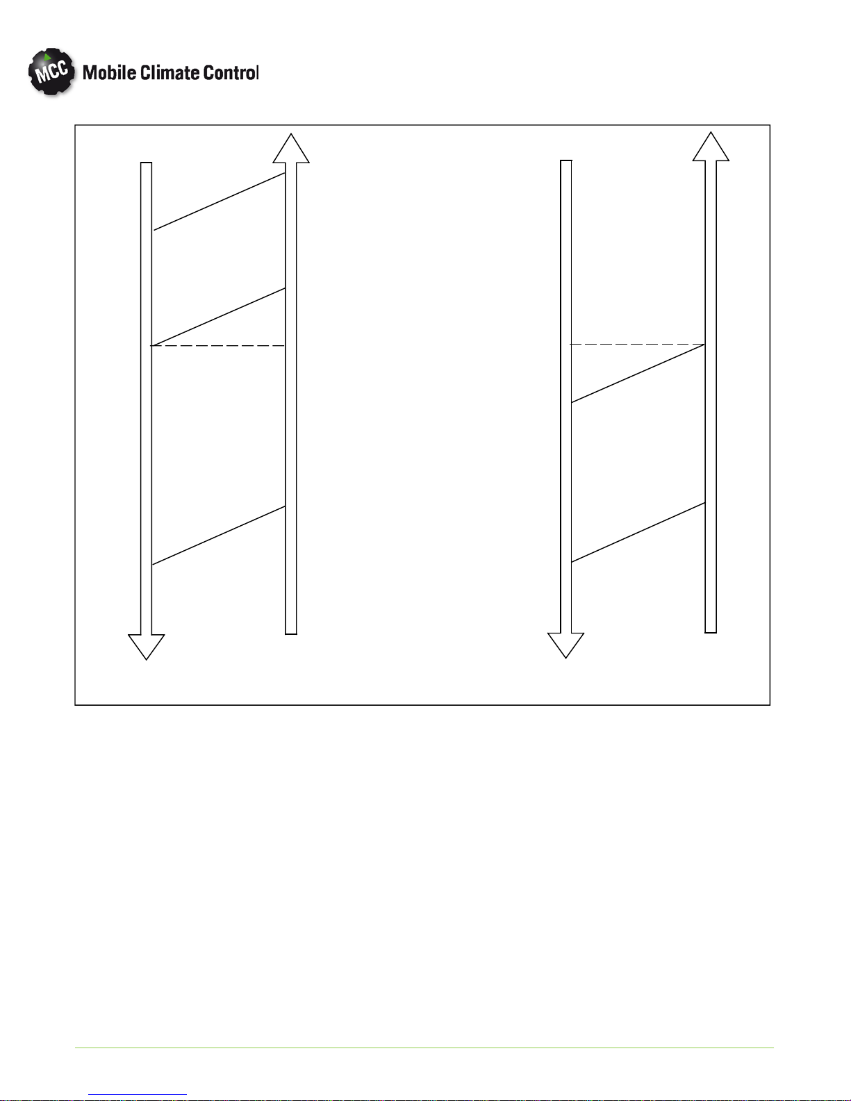
3°F
COOL
4 CYLINDER
3°F
2°F
1°F
SETPOINT
-- 1 °F
-- 2 °F
-- 3 °F
-- 4 °F
-- 5 °F
COOL
2CYLINDERS
REHEAT DUTY CYCLE
0-- 100%
2 CYLINDERS
HEAT
2°F
1°F
SETPOINT
-- 1 °F
-- 2 °F
-- 3 °F
-- 4 °F
-- 5 °F
VENT
HEAT
FLOOR BLOWERS
OFF
HEAT
WITH
FLOOR BLOWERS
AUTO/COOL
(Reheat)
© 2015 Mobile Climate Control
Figure 2-3 Capacity Control Ladder Diagrams
2--4
HEAT
T-367Rev05/2015
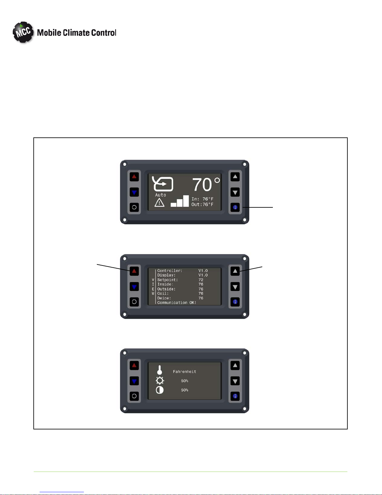
2.4.6 Display Settings
To adjust display settings, from the main menu:
c. To adjust settings, press the up or down cursor
keys to scroll to desired parameter (Item 3 in
Figure 2-1).
a. Press the “Information” button to enter the
“View” screen (Item 4 in Figure 2-1).
b. Press and releaseboth “Temperature Control UP”
and “Cursor UP” buttons (Items 3 in Figure 2-4)
to access the display set- up screen.
Main Menu Screen
Temperature
Control UP
d. To adjust settings, press the up or down temperat
ure control keys to scroll to adjust parameter
e. After adjustment, press “Information” button
(Item 4 in Figure 2-1) to exit set-up screen.
Info Button
Cursor UP
© 2015 Mobile Climate Control
View Screen
Display Set-Up Screen
Figure 2-4 HVAC DISPLAY SETTINGS
2--5
T-367Re v. 05/2015
 Loading...