

MCC MIIC-101, SMB-SW User Manual
User’s Guide
I2C Bus / SMBus Monitor
and
2
C/SMBus Software Analyzer
I
Version 1.6
Micro Computer Control Corporation
www.mcc-us.com

This user’s guide is for use with MCC’s I2C/SMB us Monitor
(#MIIC-101), and I
Table of Content s:
2
C/SMBus Analyzer Software (#SMB - SW)
System Requirements (Remote Mode Only)
System Components
Optional Add-On Parts
Introduction
2
I
C Bus / SMBus Monitor.................................. 1
.................................................. 1
............................................I
.........................................I
Product Features ......................................... 2
Input / Output Ports
2
I
C Bus / SMBus Port..................................... 3
........................................... 3
RS-232 Serial Port ....................................... 4
External Trigger Port ..................................... 4
Set-Up
...................................................... 5
.........................I
Connecting a Power Source ................................ 5
Internal Battery Power .................................... 5
External Power .......................................... 5
Connecting to an I
Connecting the External Trigger............................. 6
Connecting the Serial Cable (optional)........................ 6
Operating Modes
............................................. 9
Stand-Alone Operation .................................... 9
Quick Start ............................................. 9
Address Select Mode .................................... 10
View Status Mode....................................... 10
2
C Bus / SMBus........................... 6

Trace Mode............................................ 11
View Data Mode........................................ 11
Remote Mode .......................................... 13
Bus Simulation Mode.................................... 13
Remote Operation....................................... 14
2
I
C Bus / SMBus Analyzer Software
Quick Start ............................................ 15
Software Installation ..................................... 16
Equipment Setup ....................................... 16
Starting The Program .................................... 16
Program Controls:....................................... 17
Button Controls: ........................................ 17
Check Box Controls:..................................... 18
Grid Control:........................................... 19
Menu Controls:......................................... 19
............................. 15
Application Program Interface
Command Syntax ....................................... 22
Baud Rate Select........................................ 23
ASCII Remote Select .................................... 24
Binary Remote Select .................................... 25
CTS/RTS Handshaking Command.......................... 27
Dump Trace Buffer...................................... 27
Enable Bus Simulation ................................... 28
Remote Trace .......................................... 29
Select Address.......................................... 29
Remote ............................................... 29
Test System............................................ 30
Help ................................................. 31
Appendix A - Solving Proble ms
................................. 22
................................. 32
Appendix B - Oper ating Specifications
Appendix C - Seri al Port Co mmands
........................... 34
............................ 34

LIMITED WARRANTY
Micro Computer Control (MCC) Corporation warrants this products against
defects i n materials and workmanship for a peri od of ni nety (90) days from
the original date of purchase.
This limited warranty is not appl i cable to:
1) Normal wear and tear;
2) Abuse, unreas onabl e use, mistreatment or neglect;
3) Damage caused by the equipment or system with whic h t he product is
used; or
4) Damage caused by modifi cation or repair not aut hori zed by MCC.
THIS WARRANTY IS EXTENDED TO THE ORIGINAL PURCHASER
ONLY AND IS IN LIEU OF ALL OTHER WARRANTIES, INCLUDING
IMPLIED WARRANTIES OF MERCHANTABILITY AND FIT NE SS FOR
A PARTICULAR PURPOSE.
In no event will MCC be liable for any incidental or consequential damages.
During the warranty period, MCC will repair, replace or refund the purchase
price of any product found defecti ve at its opti on. Returned item s require
an RMA (Return Material Aut hori zation) issued by MCC, must be c aref u l l y
packaged, insured for the full repl acement value, with shipping charges
prepaid, before the return will be accept ed.

I
System Requirements
(Remote Mode Only)
The I2C/SMBus Monitor can be used in stand-al one mode or host
2
comput er controlled remote mode. To use the I
2
remote mode with the I
C/SMBus A nal yzer Software, your PC m ust meet
the following requirements:
IBM PC or 100% compatible System.
4MB of RAM.
1 MB Free Hard Disk Space.
Microsoft Windows 3. 1, 3.11, 95, 98, NT or above.
Mouse.
VGA or Better Monitor.
1 Free RS-232 Serial Port (COM1, 2, 3,4).
C/SMBus Monitor in
System Components
The I2C/SMBus Monitor package includes the following com ponents:
2
1. I
2. I
3. I
4. RS-232 Serial Cable, 7Ft. with DB-25 adapter (#MEE-P S).
5. W al l Transformer (depending on power conf i gurat i on selected, see next
6. User’s Guide.
7. I
C/SMBus Monitor (#MI IC-101)
2
C Bus Clip Lead Cable, 2Ft. (#CABCL).
2
C Interface Cable, 4Ft. (#CAB 4).
pg).
2
C/SMBus A nal yzer S oftware (#SMB-SW) for rem ote usage, (incl uded
with MIIC-101K only)

Power Configurations
Standard (#MIIC-101) 120 VAC 60Hz 6W to 5VDC
300mA Regulat ed, USA Plug.
European (#MIIC-101E) 220V~50Hz 5W to 5V 300m A
Regulated, European P l ug.
International (#MIIC-101I) 120 VAC 60Hz 6W to 5VDC
300mA Regulat ed, USA Plug,
220/240VAC, 50-60Hz, up to 50
W atts Converter, and I nternational
Adapter Set.
Optional Add-On Parts
1. I2C/SMBus Analyzer Software (#SMB-SW).
2
2. I
3. I
4. I
C Interface Cable, 8Ft. (#CAB 8).
2
C Interface Cabl e, 16Ft. (#CAB16).
2
C Bus Clip Lead Cable, 2Ft. (#CABCL).
I2C Bus / SMBus
Monitor
Model No. MIIC-101

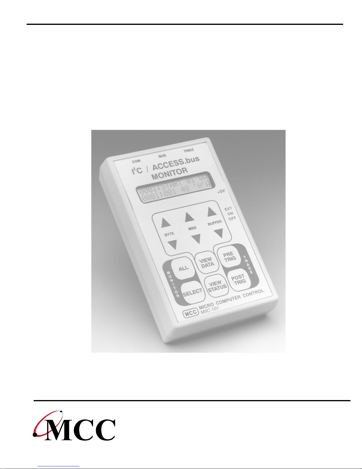
Introduction
I2C Bus / SMBus Monitor
1
The
Integrated Circuit (
System Management Bus
connected to an I
2
I
C Bus / SMBus Monitor
2
) Bus developed by Philips Semiconductors and the
I
C
(SMBus
2
C Bus or SMBus network, the I2C Bus / SMBus Monitor
is a Troubleshoot i ng Tool f or the Inter-
) developed by Intel Corporat i on. W hen
can capture and display bus m essage activi ty.
2
The I
remote. In
capture and displ ay of bus mes sages. In
C Bus / SMBus Monitor can operate in t wo m odes, stand-alone and
stand-alone mode
, the built -i n di splay and keypad supports the
remote mode
, the moni tor is
controlled by a hos t comput er vi a an RS-232 serial communic ations port.
For remote mode operation, MCC offers an optional Windows-based
Bus / SMBus Analyzer
software (#SMB-SW) to provi de remote cont rol of
2
C
I
the monit or from a PC. This software allows bus message data t o be
captured, logged, filtered, displayed, and analyzed using one of several
built-in protocol parsers, i ncluding the dis pl ay of Smart Battery Syst em
(
SBS
) mess ages in engineering units .
In addition to MCC’s standard soft ware, a c ustomer may also develop
custom software to meet special processing requirements. Custom
software can cont rol , collect , and upl oad bus mess age data to a host
system. This provides a powerful tool for integrati ng the monitor into an
automatic manufacturing-test environment. Remote cont rol i s
accom pl i shed via a series of ASCII t ext commands . A description of the
monitor comm and set is provided in the Applicati on Program Interface
section of this m anual .
2
The complete I
C Bus / SMBus Monitor package c onsists of a hand-held
unit, connecting clip-l ead and i nterface cables, power supply, and optional
W i ndows-bas ed analyzer software.

2
Product Features
I2C Bus and SMBus Compatible.
Captures bus t raf fic to 100kHz with minim al clock-s t retching
requirements.
Compatibl e with 3.3 to 5 volt bus logic.
Trace Buffer stores up to 2700 messages. Unl i mited when operated in
remote mode.
Stand-Alone and Remote Operating Modes.
RS-232 Port supports Host Computer communication.
Optional sof t ware integrates monitor and PC resources.

Input / Output Ports
3
The
TRIG
2
I
CBus/SMBus Monitor
) for connect i ng t he uni t to the network under tes t and an optional
includes t hree I/O ports (
Bus, COM
, and
host computer syst em.
This section provides a general description of these I/O ports . For specific
port use, s ee t h “Installation” section of this guide.
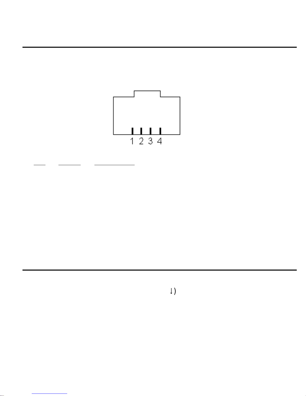
I2C Bus / SMBus Port
The monitor provi des a Molex Semicon connector (
2
the I
C Bus or SMBus.
BUS
) for connect i ng to
Pin
Signal Description
1 GND Ground Line
2 SDA Data Line
3 V Bus +5V (Optional )
4 SCL Clock Line
A clip lead cable (#CABCL), included with the unit, provi des connection to
the system under test . The Bus +5v line is used to optionally s uppl y or
source power from the target system. See the Power Supply Secti on f or
informat i on on the use of this line.
RS-232 Serial Port
4
An RS-232 serial port connector (
COM
) and cable provides c onnection to
an optional Host system. Thi s port provides remote unit control and data
uploading capabilities.
Pin
Signal Description
1 CTS Clear To Send (Host > Monitor) (Optional)
2 TX Data (Monitor > Host)
3 GND Ground Line
4 RX Data (Host > Monitor)
A serial port cable with DB-25 and DB-9 adapter, i n cluded with the unit,
provides connection to the RS-232 s e ri al comm uni cations port on an
optional Host system.
External Trigger Port
An External Trigger port connector (
TRIG
synchronization with external signals. The tri gger i s activated on a hi gh t o
low signal transit i on.
) and clip lead provides Trace

5
Set-Up
Connecting a Power Source
The I2C Bus/SMBus Monitor can be powered from either internal or
external power sources.
Internal Battery Power
An internal 9V battery provides unit power when the power switch is i n the
position. Thi s power source allows the unit t o operate stand-alone, or
ON
when another power source is unavailable.
External Power
W hen the power switch is in the
EXT
ernal position, the unit can be
powered from:
1. The BUS +5V (V) Input line.
2. A regulated +5V wall power supply (Digi -Key #T309-ND or CUI/Stack #
DPR050030-P6) through the external power jack (
~ ~ ~ ~
CA UTION
~ ~ ~ ~
+5V
).
Powering the monit or from its +5V external power jack applies power to
the BUS +5V (V ) l i ne. The BUS V line shoul d onl y be connected to the
system under test if : a) You are powering the monit or from the target
system; or, b) You are powering the target system from the monitor.
NOT CONNECT BOTH THE WALL POWER AND TARGET POWER
SUPPLIES TOGETHER.
DO

6
Connecting to an I2C Bus / SMBus
The unit provides a t est clip lead c abl e for connection to an I2C Bus or
SMBus under test. On the moni tor, the test clip cable connects t o t he
Molex Semicon modular connector marked
BUS
.
Test cli ps are provided for:
Clip ID
Signal Description
G GND Ground Line
2
DSDA I
C/SMBus Data Line
V V +5V (Optional)
2
CSCL I
C/SMBus Clock Line
For informat i on on using the +5v option, see the “Power Supply Sec tion”
of this gui de.
Connecting the External Trigger
The monitor provi des External Triggering for Trace s ynchronization with
external events. Trace synchronization allows bus traffic t o be collected
immediately before or af t er an el ectronic event.
A High-to-Low transit i on on t he External Trigger port can be used t o start
a PRE-TRIG trac e, or stop a POST-TRI G t race. See the Trace Mode
section of this guide fo r t race synchronizati on det ai l s.
Connecting the Serial Cable (optional)
The Serial Cable provides the connection bet ween the monitor and an
optional Host system. On monitor, the Serial Cable connec ts to the
modular RJ-45 connector m arker
connects to a standard RS-232 serial communicati ons port. Both DB -25
COM
. On the Host system, the cable
and DB-9 connect ors are supported.
 Loading...