

MCC 68AC430-100, 68AC430-100-4, 68AC430-100-2, 68AC430-100-5, 68AC430-100-6 Service Manual
...
T-353 Manual
OPERATION/SERVICE
© 2012 Mobile Climate Control
for
68AC430-100
T-353
REV. 01/2013

TABLE OF CONTENTS
SAFETY SUMMARY Safety-1...............................................................
DESCRIPTION 1-1....................................................................
1.1 INTRODUCTION 1-1.......................................................
1.2 GENERAL DESCRIPTION 1-2...............................................
1.2.1 Rooftop Unit 1-2......................................................................
1.2.2 Condensing Section 1-2.................................................................
1.2.3 Evaporator Section 1-2..................................................................
1.2.4 BT-324 Microprocessor 1-3..............................................................
1.3 REFRIGERATION SYSTEM COMPONENT SPECIFICATIONS 1-3.................
1.4 ELECTRICAL SPECIFICATIONS - MOTORS 1-3................................
1.5 SAFETY DEVICES 1-3......................................................
1.6 AIR CONDITIONING REFRIGERATION CYCLE 1-4............................
1.7 HEATING CYCLE 1-4.......................................................
OPERATION BT324 Controller 2-1.........................................................
2.1 STARTING, STOPPING AND OPERATING INSTRUCTIONS 2-1..................
2.1.1 Starting 2-1...........................................................................
2.1.2 Stopping 2-1..........................................................................
2.2 PRE-TRIP INSPECTION 2-1..................................................
2.3 SEQUENCE OF OPERATION BT324 2-2.......................................
2.3.1 Function of Keys when “Engine On” and controller active: 2-2...................................
2.3.2 Illuminating Indications (Display) 2-2.......................................................
2.4 OPERATING INSTRUCTIONS BT324 2-2......................................
2.4.1 Display 2-2...........................................................................
2.4.2 Interior Temperature Control 2-2..........................................................
2.4.3 Ventilation 2-2........................................................................
2.4.4 Reheat (optional) 2-2....................................................................
2.4.5 Temperature Indication 2-2..............................................................
2.5 CHANGING BETWEEN °F (FAHRENHEIT) AND °C(CELCIUS) 2-2..............
TROUBLESHOOTING 3-1................................................................
3.1 System Will Not Cool 3-1................................................................
3.2 System Runs But Has Insufficient Cooling 3-1................................................
3.3 Abnormal Pressures 3-1.................................................................
3.4 Abnormal Noise Or Vibrations 3-1.........................................................
3.5 No Evaporator Air Flow Or Restricted Air Flow 3-2...........................................
3.6 Expansion Valve Malfunction 3-2..........................................................
3.7 Heating Malfunction 3-2.................................................................
© 2012 Mobile Climate Control T-353 Rev. 01/2013
i

TABLE OF CONTENTS (Continued)
SERVICE 4-1........................................................................
4.1 MAINTENANCE SCHEDULE 4-1.............................................
4.2 REMOVING COVER 4-1.....................................................
4.3 MANIFOLD GAUGE SET 4-1................................................
4.3.1 Installing R-134a Manifold Gauge/Hose Set 4-2..............................................
4.4 REMOVING THE REFRIGERANT CHARGE 4-3...............................
4.4.1 Removing Entire System Charge 4-3.......................................................
4.5 REFRIGERANT LEAK CHECK 4-3............................................
4.6 EVACUATION AND DEHYDRATION 4-3.....................................
4.6.1 General 4-3...........................................................................
4.6.2 Preparation 4-3........................................................................
4.6.3 Procedure for Evacuation and Dehydrating System 4-4.........................................
4.7 ADDING REFRIGERANT TO SYSTEM 4-4.....................................
4.7.1 Checking Refrigerant Charge 4-4..........................................................
4.7.2 Adding Full Charge 4-4.................................................................
4.8 CHECKING FOR NONCONDENSIBLES 4-4...................................
4.9 CHECKING AND REPLACING HIGH OR LOWPRESSURE CUTOUT SWITCH 4-4...
4.9.1 Replacing High Or Low Pressure Switches 4-4................................................
4.9.2 Checking High Pressure Switches 4-5......................................................
4.9.3 Checking Low Pressure Switches 4-5.......................................................
4.10 FILTER-DRIER 4-5.........................................................
4.10.1 To Check Filter-Drier 4-5................................................................
4.10.2 To Replace Filter-Drier Assembly 4-5......................................................
4.11 SERVICING THE HEAT VALVE 4-6..........................................
4.11.1 Coil Replacement 4-6...................................................................
4.11.2 Internal Part Replacement 4-6............................................................
4.11.3 Replace Entire Valve 4-6................................................................
4.12 SERVICE VALVES 4-7.......................................................
4.13 REPLACINGRETURNAIRFILTERS 4-7.......................................
4.14 THERMOSTATIC EXPANSION VALVE 4-8....................................
4.14.1 Valve Replacement 4-9..................................................................
4.14.2 Superheat Measurement 4-9..............................................................
ELECTRICAL 5-1......................................................................
5.1 INTRODUCTION 5-1.......................................................
Table 1-1 68AC430 Models 1-1.........................................................
Table 1-2 Additional Support Manuals 1-1................................................
Table 3-1 General System Troubleshooting Procedures 3-1...................................
Table 4-1 R-134a Temperature - Pressure Chart 4-11.........................................
© 2012 Mobile Climate Control T-353 Rev. 01/2013
LIST OF TABLES
ii

LIST OF FIGURES
Figure 1-1 AC430 Rooftop Unit 1-2....................................................
Figure 1-2 Refrigerant/Heat Flow Diagram, AC430 1-5.....................................
Figure 1-3 AC430 With BT324 Control Board 1-6.........................................
Figure 3-1 BT324 Controller 2-1......................................................
Figure 4-1 Manifold Gauge Set (R-134a) 4-2..............................................
Figure 4-2 In-Line Service Connections 4-3..............................................
Figure 4-3 Checking High Pressure Switch 4-5............................................
Figure 4-4 Filter-Drier Removal 4-5....................................................
Figure 4-5 Heat Valve 4-7............................................................
Figure 4-6 Service Valve R134a (High Side) 4-7...........................................
Figure 4-7 Return Air Grill Assembly With Air Filter Showing 4-8.............................
Figure 4-8 Diffuser and Filter Element 4-8...............................................
Figure 4-9 Filter, Diffuser and Composite Frame 4-8.......................................
Figure 4-10 Return Air Grill Assembly With Diffuser And Composite Frame Showing 4-8..........
Figure 4-11 Thermostatic Expansion Valve 4-9...........................................
Figure 4-12 Thermostatic Expansion Valve Bulb and Thermocouple 4-9........................
Figure 5-2 Evaporator Motors 5-2.....................................................
Figure 5-3 Condenser Motors 5-3.....................................................
Figure 5-4 BT324 Controls With (1) Compressor 5-4.......................................
Figure 5-5 BT324 Control Circuit 5-5...................................................
Figure 5-6 AC430 With BT324 Control 5-6..............................................
Figure 5-7 AC430 With BT324 Control (Electrical Panel 91-62105-00) 5-7.......................
Figure 5-8 AC430 With BT324 Control (Electrical Panel 91-62105-00) 5-8.......................
© 2012 Mobile Climate Control T-353 Rev. 01/2013
iii

SAFETY SUMMARY
GENERAL SAFETY NOTICES
The following general safety notices supplement the specific warnings and cautions appearing elsewhere in this
manual. They are recommended precautions that must be understood and applied during operation and
maintenance of the equipment covered herein. A listing of the specific warnings and cautions appearing
elsewhere in the manual follows the general safety notices.
FIRST AID
An injury, no matter how slight, should never go unattended. Always obtain first aid or medical attention
immediately.
OPERATING PRECAUTIONS
Always wear safety glasses.
Keep hands, clothing and tools clear of the evaporator and condenser fans.
No workshouldbe performedon the unituntilall start-stop switchesare placed in the OFF position, and power
supply is disconnected.
Always work in pairs. Never work on the equipment alone.
In case of severe vibration or unusual noise, stop the unit and investigate.
MAINTENANCE PRECAUTIONS
Beware of unannounced starting of the evaporator and condenser fans. Do not open the unit cover before
turning power off.
Be sure power is turned off before working on motors, controllers, solenoid valves and electrical controls. Tag
circuit breaker and power supply to prevent accidental energizing of circuit.
Do not bypass any electrical safety devices, e.g. bridging an overload, or using any sort of jumper wires.
Problems with the system should be diagnosed, and any necessary repairs performed by qualified service
personnel.
When performing any arc welding on the unit, disconnect all wire harness connectors from the modules in the
control box. Do not remove wire harness from the modules unless you are grounded to the unit frame with a
static-safe wrist strap.
In case of electrical fire, open circuit switch and extinguish with CO2(never use water).
© 2012 Mobile Climate Control T-353 Rev. 01/2013
Safety--1
SPECIFIC WARNINGS AND CAUTIONS
WARNING
Be sure to observe warnings listed in the safety summary in the front of this manual before
performing maintenance on the hvac system
WARNING
Read the entire procedure before beginning work. Park the vehicle on a level surface, with
parking brake applied. Turn main electrical disconnect switch to the off position.
WARNING
Do Not Use A Nitrogen Cylinder Without A Pressure Regulator
WARNING
Do Not Use Oxygen In Or Near A Refrigeration System As An Explosion May Occur.
WARNING
The Filter-drier May Contain Liquid Refrigerant. S lowly Loosen The Connecting Nuts And
AvoidContactWithExposedSkinOrEyes.
CAUTION
The AC430 Rooftop Systems has R134a serviceport couplings installed on the compressor and
on the unit piping.
CAUTION
To prevent trapping liquid refrigerant in the manifold gauge set be sure set is brought to
suction pressure before disconnecting.
© 2012 Mobile Climate Control T-353 Rev. 01/2013
Safety--2
SECTION 1
DESCRIPTION
1.1 INTRODUCTION
This manual contains Operating Instructions,
Service Instructions and Electrical Data for the
Model 68AC430 Air Conditioning and Heating
equipment furnished by Mobile Climate Control as
showninTable1-1.
Model 68AC430 systems consists of a Rooftop unit
containing the condensing section, the evaporator
section and engine compartment mounted
compressor(s). To complete the system, the air
conditioning and heating equipment interfaces with
an optional drivers evaporator (dash-air), electrical
cabling, refrigerant piping, engine coolant piping (for
heating), duct work and other components
furnishedby Mobile Climate Control and/or the bus
manufacturer.
Additional support manuals are shown in Table 1-2.
Operation of the unit is controlled automatically by
an electronic thermostat. The controls maintain the
vehicle'sinterior temperature at the desired set point.
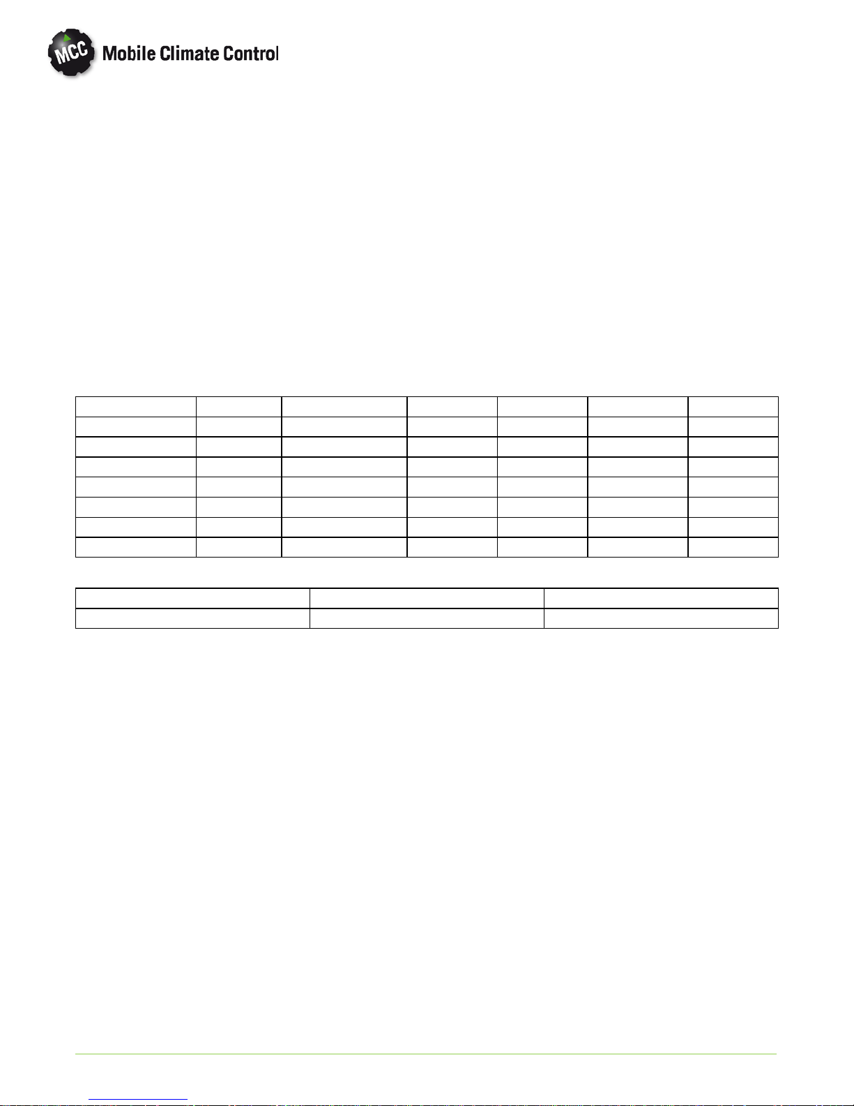
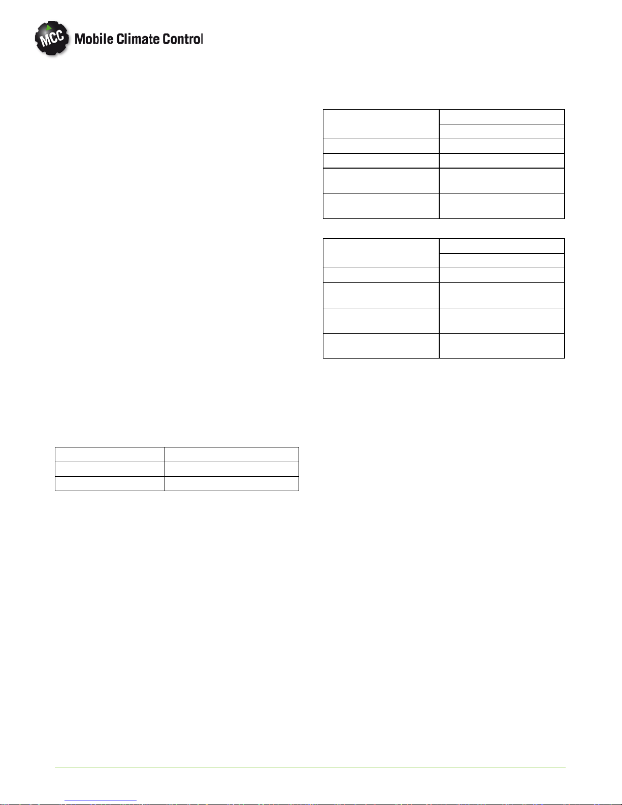
Table 1-1 68AC430 Models
Model Voltage Controller With Heat Dual Loop Single Loop Roof Radius
68AC430-100 12 VDC BT324 Yes X 4.6M
68AC430-100-2 12 VDC BT324 No X 4.6M
68AC430-100-4 12 VDC BT324 Yes X 4.6M
68AC430-100-5 12 VDC BT324 No X 4.6M
68AC430-100-6 12 VDC BT324 Yes X 7.8M
68AC430-100-7 12 VDC BT324 No X 7.8M
68AC430-100-8 * 12 VDC BT324 No X 7.8M
Table 1-2 Additional Support Manuals
MANUAL NUMBER EQUIPMENT COVERED TYPE OF MANUAL
T-353PL 68AC-430-100 Service Parts List
* Denotes Special Packaging
© 2012 Mobile Climate Control T-353 Rev. 01/2013
1--1
1.2 GENERAL DESCRIPTION
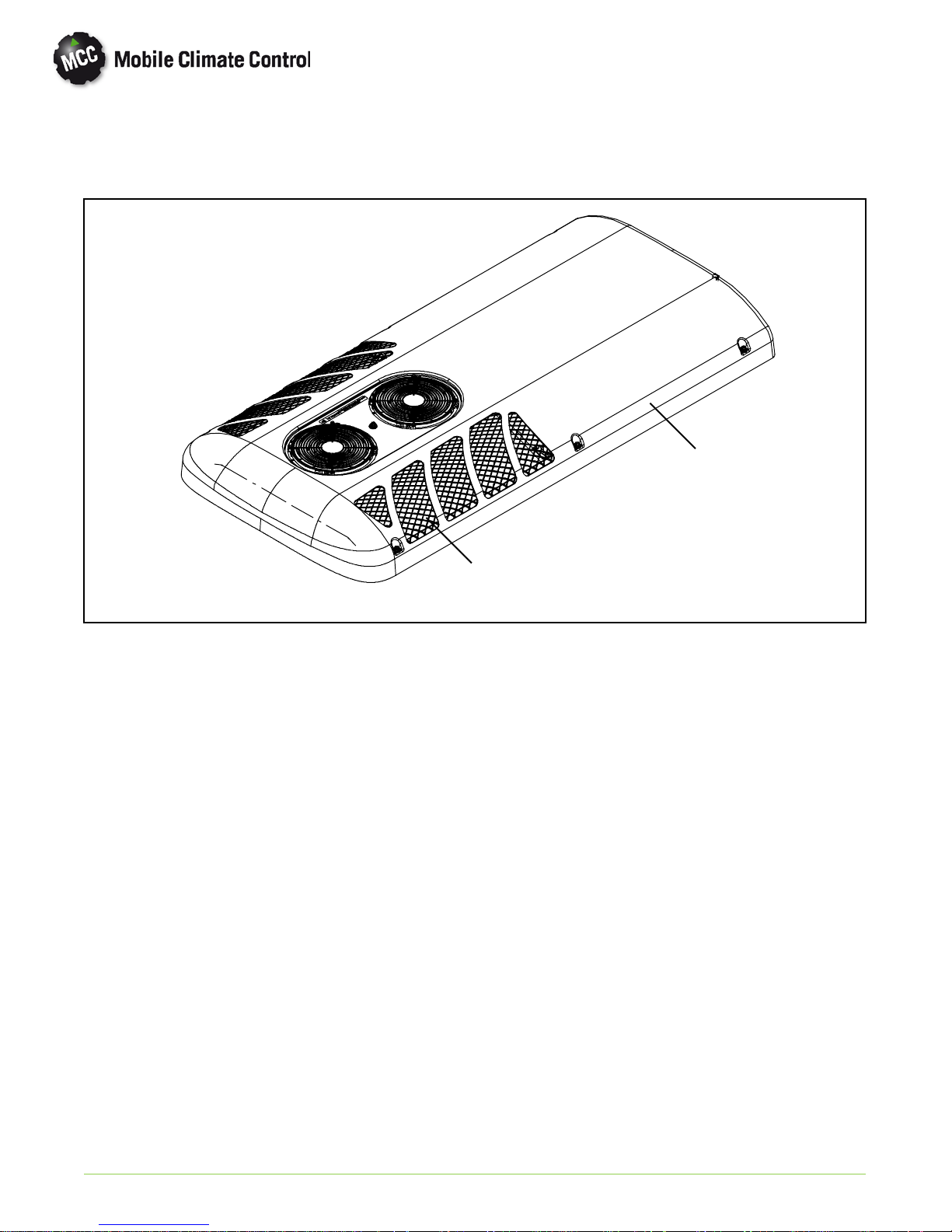
1.2.1 Rooftop Unit
The rooftop unit includes the condenser section and the evaporator section (See Figure 1-1).
Evaporator Section
Figure 1-1 AC430 Rooftop Unit
1.2.2 Condensing Section
The condensing section includes the condenser
coils, two (2)fan and mot or assemblies, receiver,
filter-drier and filter-drier service valves.
The condenser coils provide heat transfer surface for
condensing refrigerant gas at a high temperature and
pressure into a liquid at high temperature and
pressure. The condenser fans circulate ambient air
across the outside of the condenser tubes at a
temperature lower than refrigerant circulating inside
the tubes; this results in condensation of the
refrigerant into a liquid. The receiver collects and
stores liquid refrigerant. The receiver is also fitted
with a pressure relief valve which protects the system
from unsafe high pressure conditions. The
filter-drier removes moisture and debris from the
liquid refrigerant before it enters the thermostatic
expansion valve in the evaporator assembly. The
service valves enable isolation of the filter-drier for
service.
Condenser Section
1.2.3 Evaporator Section
The evaporatorsection includesthe evaporatorcoils,
two (2) single-shaftedblower/motor assemblies,two
(optional) heater coil assemblies, a thermostatic
expansion valve and condensate drain connections.
The evaporator coils provide heat transfer surface
for transferring heat from air circulating over the
outside of the coil to refrigerant circulating inside the
tubes; thus providing cooling. The heating coils (if
equipped) provide a heat transfer surface for
transferring heat from engine coolant water
circulating inside the tubes to air circulating over the
outside surface of the tubes, thus providing heating.
The fans circulate the air over the coils. The air filters
remove dirt particles from the air before it passes
over the coils. The thermostatic expansion valve
meters the flow of refrigerant entering the
evaporator coils. The heat valve controls the flow of
engine coolant to the heating co ils upon receipt of a
signal from the controller. The condensate drain
connections provide a means for connecting tubing
for disposing of condensate collected on the
evaporator coils during cooling operation.
© 2012 Mobile Climate Control T-353 Rev. 01/2013
1--2
1.2.4 BT-324 Microprocessor
1.4 ELECTRICAL SPECIFICATIONS - MOTORS
This BT-324 controller has three (3) modes, Auto,
Vent (Cycle clutch type) and Heat.
In the auto mode the compressor is energized while
the evaporator and condenser fans are operated to
providerefrigerationas required. The compressor(s)
capacity is matched to the bus requirements. Once
interior temperature reaches the desired set po int,
the compressor(s) is de-energized.
In the heat mode the heat valves are opened to allow
a flow of engine coolant through the heat coils
located in the evaporator section. The evaporator
fans operate to circulate air over the heat coils in the
same manner as the cooling mode.
1.3 REFRIGERATION SYSTEM COMPONENT SPECIFICATIONS
a. Refrigerant Charge R-134a (Approximate)
NOTE
Refrigerant charge will depend on hose
lengths and diameters; or if there is an InDash unit (front evaporator). The following
should only be used as a guideline.
AC430 Single Loop TM-21 Compressor
11 Pounds (5 kg)
b. Compressors
Compressor
Weight, (Dry) 7.5 Lbs. (3.4 kg)
Oil Charge 6.1 Oz. (180 cc) PAG
c. Thermostatic Expansion Valves:
TDEN 5.8 TR
Superheat Setting Factory Set at 12°F(±1.8°F)
6.7°C (±1°C)
TGEN 4.5
Superheat Setting Factory Set at 7.2°F(4°C)
MOP70psig(4.8bar)
TM-21
a. Evaporator Blower/Motor
Evaporator Motor
Horsepower (kW) .375 (.28)
Full Load Amps (FLA) 20.7
Operating Speed
High(RPM)
Bearing Lubrication
b. Condenser Fan Motor
Condenser Motor
Horsepower (kW) 1/4 (.18)
Full Load Amps (FLA) @
13.5 VDC
Operating Speed
High(RPM)
Bearing Lubrication
c. Return Air Sensor
Input Range: -40 to 176° F(-40to80°C)
Output: 20K ohms at 77° F(25°C)
d. Ambient Sensor (location chosen by Installer)
Input Range: -40 to 302° F (-40 to 150°C)
Output: 20K ohms at 77° F(25°C)
Opens at: 25° F(10°C)
Closes at: 35° F(1.7°C)
Brushless
12 VDC
3250
Factory Lubricated
(additional grease not required)
Permanent Magnet
12 VDC
14.4
3222
Factory Lubricated
(additional grease not required)
1.5 SAFETY DEVICES
System components are protected from damage
caused by unsafe operating conditions with safety
devices. Safety devices with Mobile Climate Control
supplied equipment include high pressure switch
(HPS), low pressure switch (LPS), circuit breakers
and fuses.
d. High Pressure Switch (HPS)
Opens at: 360 ±10 psig (20.41 ±0.68bar)
Closes at: 280 ±10 psig (13.61 ±0.68bar)
e. Low Pressure Switch (LPS)
Opens at: 6 ±3psig (0.41 ±0.20 bar)
Closes at: 25 ±3psig(1.7±0.20 bar)
© 2012 Mobile Climate Control T-353 Rev. 01/2013
Normally Closed
Normally Open
a. Pressure Switches
High Pressure Switch (HPS)
During the air co nditioning cycle, compressor clutch
operation will automatically stop if the HPS switch
contacts open due to an unsafe operating condition.
Opening HPS contacts de-energizes the compressor
clutch shutting down the compressor. The high
pressure switch (HPS) is installed in the condenser
section.
1--3

Low Pressure Switch (LPS)
The low pressure switch is installedin the evaporator
section and opens on a pressure drop to shut down
the system when a low pressure condition occurs.
b. Fuses and Circuit Breakers
The Relay Board is p ro tected against high current by
an OEM supplied circuit breaker or fuse located in
the bus battery compartment (150 Amp for 12 VDC
systems). Independen t 20 Amp, 12 VDC fuses
protect each condenser motor. Independent 25
Amp, 12 VDC fuses protect each evaporator motor.
Output circuits are pro tected by additional 2,3,5 and
10 Amp fuses according to circuit loads. During a
high current condition, the fuse may open.
1.6 AIR CONDITIONING REFRIGERATION CYCLE
When air conditioning (cooling) is selected by the
controller, the unit operates as a vapor compression
system using R-134a as a refrigerant (See Figure 1-2
refrigerant flow diagram). The main components of
the system are the A/C compressor, air-cooled
condenser coils, receiver, filter-drier, th ermo static
expansion valve, liquid line solenoid valve (if
equipped), and evaporator coils.
The compressor raises the pressure and the
temperature of the refrigerant and forces it into the
condenser tub es. The condenser fan circulates
surrounding air (which is at atemperature lower than
the refrigerant) over the outside of the condenser
tubes. Heat transfer is established from the
refrigerant (inside the tubes) to the condenser air
(flowing over the tubes). The condenser tubes have
fins designed to improve the transfer of heat from
the refrigerant gas to the air; this removal of heat
causes the refrigerant to liquefy, thus liquid
refrigerant leaves the condenser and flows to the
receiver.
The refrigerant leaves the receiver and passes
through the receiver outlet/service valve, th rou gh a
filter-drier where a desiccant keeps t h e refrigerant
clean and dry.
From the filter-drier, the liquidrefrigerant then flows
through the liquid line to the sight-glass and then to
the thermostatic expansion valve. The thermal
expansion valvereduces pressure and t em p erature of
the liquid and meters the flow of liquid refrigerant to
the evaporator to obtain maximum use of the
evaporator heat transfer surface.
The low pressure, low temperature liquid that flows
into the evaporator tubes is colder than the air that is
circulated over the evaporator tubes by the
evaporator fans (fans). Heat transfer is established
from the evaporator air (flowing over the tubes) to
the refrigerant (flowing inside the tubes). The
evaporator tubes have aluminum fins to increase
heat transfer from the air to the refrigerant;therefore
the cooler air is circulated to the interior of the bus.
The transfer of heat from the air to the low
temperature liquid refrigerant in the evaporator
causes the liquid to vaporize. This low temperature,
low pressure vapor passes through the suction line
and returns to the compressor where the cycle
repeats.
1.7 HEATING CYCLE
Heating circuit (See Figure 1-2) components
furnished by Mobile Climate Control include the
heater cores and solenoid operated heat valves.
Components furnished by the bus manufacturer
may include a water temperature switch (WTS) and
boost water pump.
The controller automatically controls the heat valves
during the heating mode to maintain required
temperatures inside the bus. Engine coolant (glycol
solution) is circulated through the heating circuit by
the engine and an auxiliary boost water pump. When
the heat valve solenoids are energized, the valves will
open to allow engine coolant to flow through the
heater coils. The valves are normally closed so that if
a failure occurs, the system will be able to cool.
© 2012 Mobile Climate Control T-353 Rev. 01/2013
1--4
Discharge
Liquid
Suction
Coolant
14
11
11
13
3
10
12
CONDENSER
10
EVAPORATOR
8
77
8
2
6
9
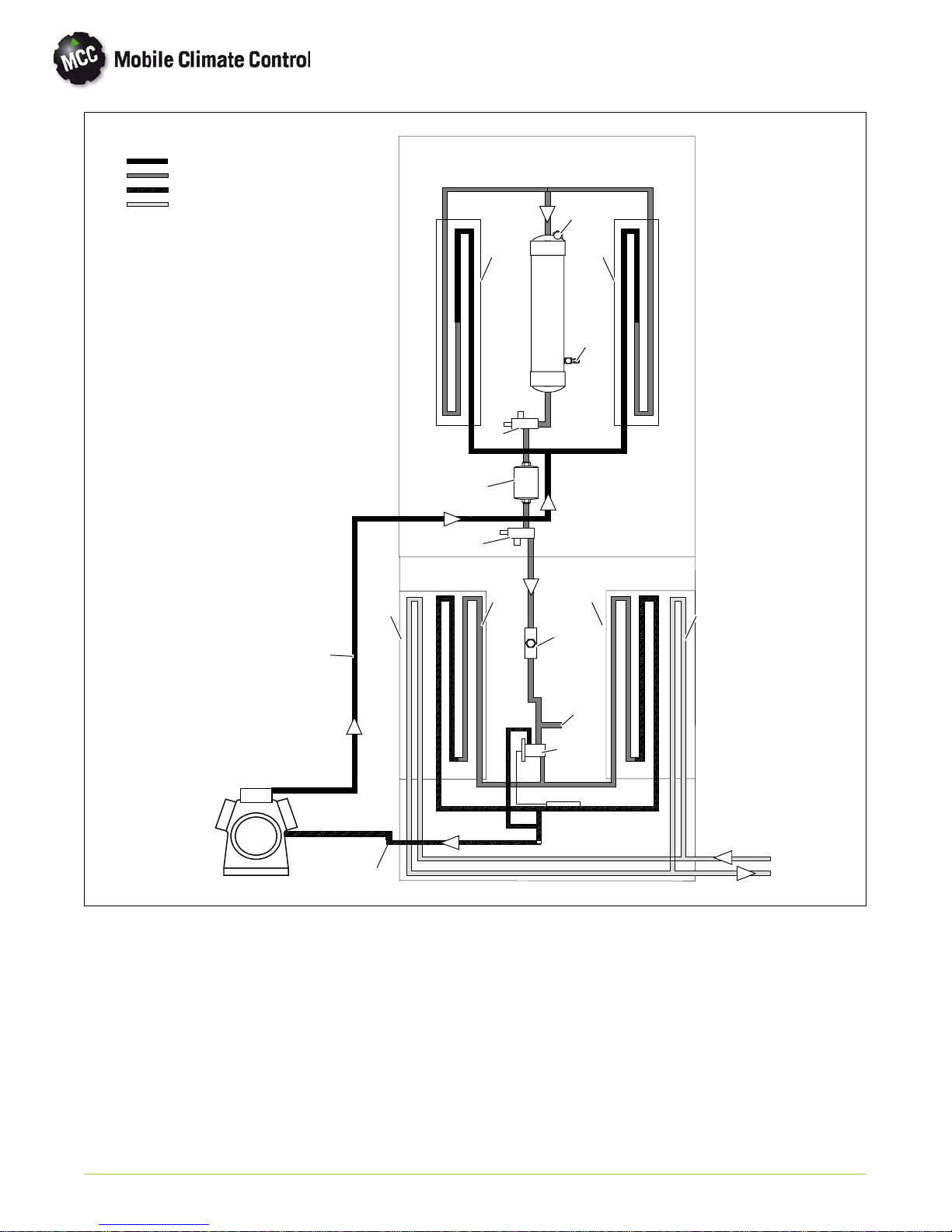
Figure 1-2 Refrigerant/Heat Flow Diagram, AC430
1. Thermal Expansion Valve
2. Liquid Line Sight Glass
3. Fusible Plug
4. Dash Air Liquid Line
5. Suction Line
6. Discharge Line
7. Heater Coil
4
1
5
8. Evaporator Coil
9. Compressor
10. Service Valve
11. Condenser Coil
12. Filter-Drier
13. Receiver
14. Receiver Liquid Level Sight Glass
© 2012 Mobile Climate Control T-353 Rev. 01/2013
1--5
13
4
121110987
6
1
3
17
5
14
15
16
2
22
20
18
19
21
23
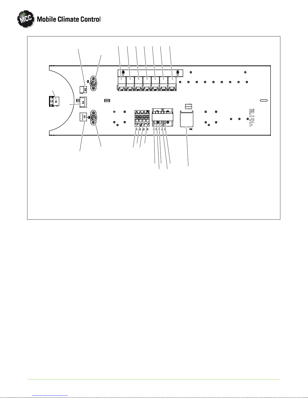
Figure 1-3 AC430 With BT324 Control Board
1. X3, Connector, Controller/Driver Display
2. X11, Connector, Evaporator Blower Motors
3. X12, Connector, Condenser Fan Motors/
High Pressure Switch
4. X13, Connector, Low Pressure Switch, Fresh
Air Flap
5. POS, 12VDCPower Connection
6. NEG, Ground Connection
7. CF1, Condenser Fan Relay 1
8. CF2, Condenser Fan Relay 2
9. LLSV, Liquid Line Solenoid Valve Relay
10. AC1, Condenser Fan On Relay
11. AC2, Condenser Fan On Relay
12. HTR1, Relay, Evaporator High Speed
13. HTR2, Relay, Evaporator Low Speed
14. F1, Fuse, Evaporator Motor
15. F2, Fuse, Evaporator Motor
16. F3, Fuse, Condenser Motor
17. F4, Fuse, Condenser Motor
18. F5, Fuse, LLSV
19. F6, Fuse, Condenser Fan Relay
20. F7, Fuse, Pressure Switch Relay
21. F8, Fuse, Heat Valve/ Pump Relay
22. F9, Fuse, Heat Valve/Floor Relay
23. RAS, Return Air Sensor
© 2012 Mobile Climate Control T-353 Rev. 01/2013
1--6
 Loading...