

MBW VS77M User Manual
OPERATOR’S SAFETY
AND SERVICE MANUAL
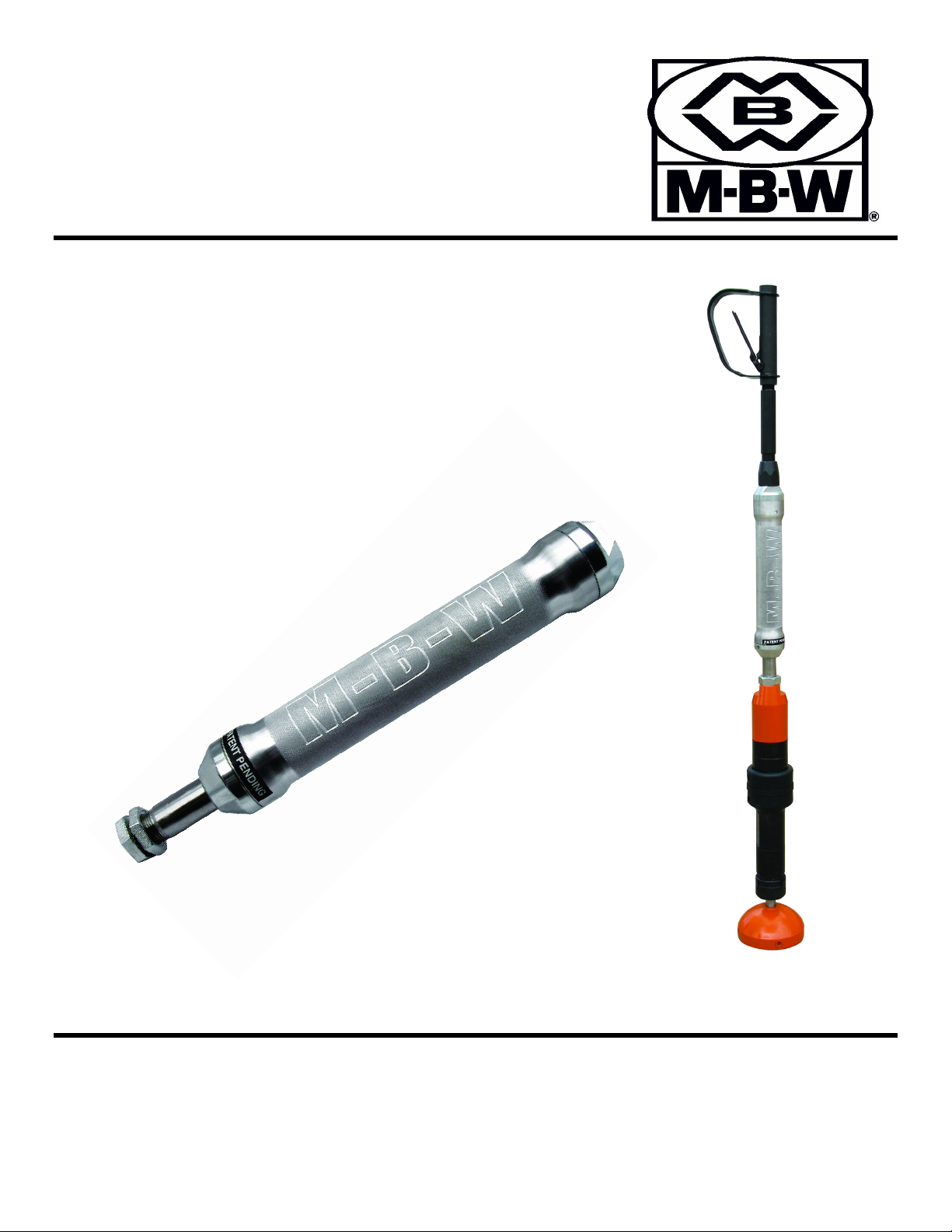
VIBRATION
SUPPRESSOR
& ERGOTAMP
This manual covers the following serial numbers
and higher for each model listed:
VS77...........1110640
VS77M........1110640
ErgoTamp....2110258
PROBLEM SOLVING TECHNOLOGIES
MBW, Inc.
250 Hartford Rd • PO Box 440
Slinger, WI 53086-0440
Phone: (262) 644-5234
Fax: (262) 644-5169
Email: mbw@mbw.com
Website: www.mbw.com
MBW (UK) Ltd.
Units 2&3 CochraneStreet
Bolton BL3 6BN
England, UK
Phone: 44 (0) 01204 387784
Fax: 44 (0) 01204 387797
E-mail: mbwuk@btinternet.com
MBW FRANCE S.A.R.L.
Z.A. d’Outreville
5 Rue Jean Baptiste Néron,
60540 BORNEL
France
Phone:+33 (0) 3 44 07 15 96
Fax: +33 (0) 3 44 07 41 28
Email: mbwfrance@free.fr
L18678 / 2.14L
©MBW, Inc. 2014
Printed in the USA

TABLE OF CONTENTS
Safety Information . . . . . . . . . . . . . . . . . . . . . . 1
Introduction . . . . . . . . . . . . . . . . . . . . . . . . . . . . . . . . . 1
Safety Precautions . . . . . . . . . . . . . . . . . . . . . . . . . . . 1
Safety Decals . . . . . . . . . . . . . . . . . . . . . . . . . . . . . . . 1
Specifications. . . . . . . . . . . . . . . . . . . . . . . . . . 2
Operation . . . . . . . . . . . . . . . . . . . . . . . . . . . . . 3
Introduction . . . . . . . . . . . . . . . . . . . . . . . . . . . . . . . . . 3
Installation. . . . . . . . . . . . . . . . . . . . . . . . . . . . . . . . . . 3
Before Starting & Operating . . . . . . . . . . . . . . . . . . . . 3
Operating Ergo and Pole tamps . . . . . . . . . . . . . . . . . 4
Storage . . . . . . . . . . . . . . . . . . . . . . . . . . . . . . . . . . . . 4
Maintenance . . . . . . . . . . . . . . . . . . . . . . . . . . . 5
Maintenance Schedule . . . . . . . . . . . . . . . . . . . . . . . . 5
Fluid Levels. . . . . . . . . . . . . . . . . . . . . . . . . . . . . . . . . 5
Tamper Oil . . . . . . . . . . . . . . . . . . . . . . . . . . . . . . . . . 5
Vibration Suppressor Oil . . . . . . . . . . . . . . . . . . . . . . 5
Service. . . . . . . . . . . . . . . . . . . . . . . . . . . . . . . . 6
General. . . . . . . . . . . . . . . . . . . . . . . . . . . . . . . . . . . . 6
Vibration Suppressor Disassembly . . . . . . . . . . . . . . 6
Vibration Suppressor Assembly . . . . . . . . . . . . . . . . . 6
Tamper Disassembly. . . . . . . . . . . . . . . . . . . . . . . . . 6
Tamper Assembly . . . . . . . . . . . . . . . . . . . . . . . . . . . 7
Suppressor Replacement Cycles and Tolerances . . . 7
Tamper Replacement Cycles and Tolerances . . . . . . 7
Replacement Parts . . . . . . . . . . . . . . . . . . . . . . 9
Vibration Suppressor Assembly . . . . . . . . . . . . . . . . 10
Threaded Adapters. . . . . . . . . . . . . . . . . . . . . . . . . . 12
Tamper Assembly . . . . . . . . . . . . . . . . . . . . . . . . . . 14
Warranty . . . . . . . . . . . . . . . . . . . . . . . . . . . . . 16

This page intentionally left blank
SAFETY INFORMATION
WARNING
CAUTION
Introduction
This Safety Alert Symbol is used to call attention
to items or operations which may be dangerous
to those operating or working with this
equipment. The symbol can be found
throughout this manual and on the unit. Please read these
warnings and cautions, along with all decals, carefully
before attempting to operate the unit. Make sure every
individual who operates or works with this equipment is
familiar with all safety precautions.
GENERAL WARNING. Indicates information
important to the proper operation of the
equipment. Failure to observe may result in
damage to the equipment and/or severe bodily
injury or death.
GENERAL CAUTION. Indicates information
important to the proper operation of the
equipment. Failure to observe may result in
damage to the equipment.
Safety Precautions
LETHAL EXHAUST GAS: An internal
combustion engine discharges carbon
monoxide, a poisonous, odorless, invisible
gas. Death or serious illness may result if
inhaled. Operate only in an area with proper
ventilation. NEVER OPERATE IN A
CONFINED AREA!
SAFETY GUARDS: It is the owner's
responsibility to ensure that all guards and
shields are in place and in working order.
NOISE PROTECTION: Wear OSHA specified
hearing protection devices.
EYE PROTECTION: Wear OSHA specified
eye shields, safety glasses, and sweat bands.
FOOT PROTECTION: Wear OSHA specified
steel-tipped safety shoes.
HEAD PROTECTION: Wear OSHA specified
safety helmets.
DUST PROTECTION: Wear OSHA specified
dust mask or respirator.
OPERATOR: Keep children and bystanders
off and away from the equipment.
REFERENCES: For details on safety rules and regulations
in the United States, contact your local Occupational Safety
and Health Administration (OSHA) office. Equipment
operated in other countries must be operated and serviced
in accordance and compliance with any and all safety
requirements of that country. The publication of these
safety precautions is done for your information. MBW does
not by the publication of these precautions, imply or in any
way represent that these are the sum of all dangers present
near MBW equipment. If you are operating MBW
equipment, it is your responsibility to insure that such
operation is in full accordance with all applicable safety
requirements and codes. All requirements of the United
States Federal Occupational Safety and Health
Administration Act must be met when operated in areas that
are under the jurisdiction of that United States Department.
SAFE DRESS: Do not wear loose clothing,
rings, wristwatches, etc. near machinery.
Safety Decals
The MBW Vibration Suppressor has a warning scribed into
the body tube of the device. If this warning becomes
damaged or unreadable, replace outer tube. This
component is available from authorized MBW distributors.
- 1 -
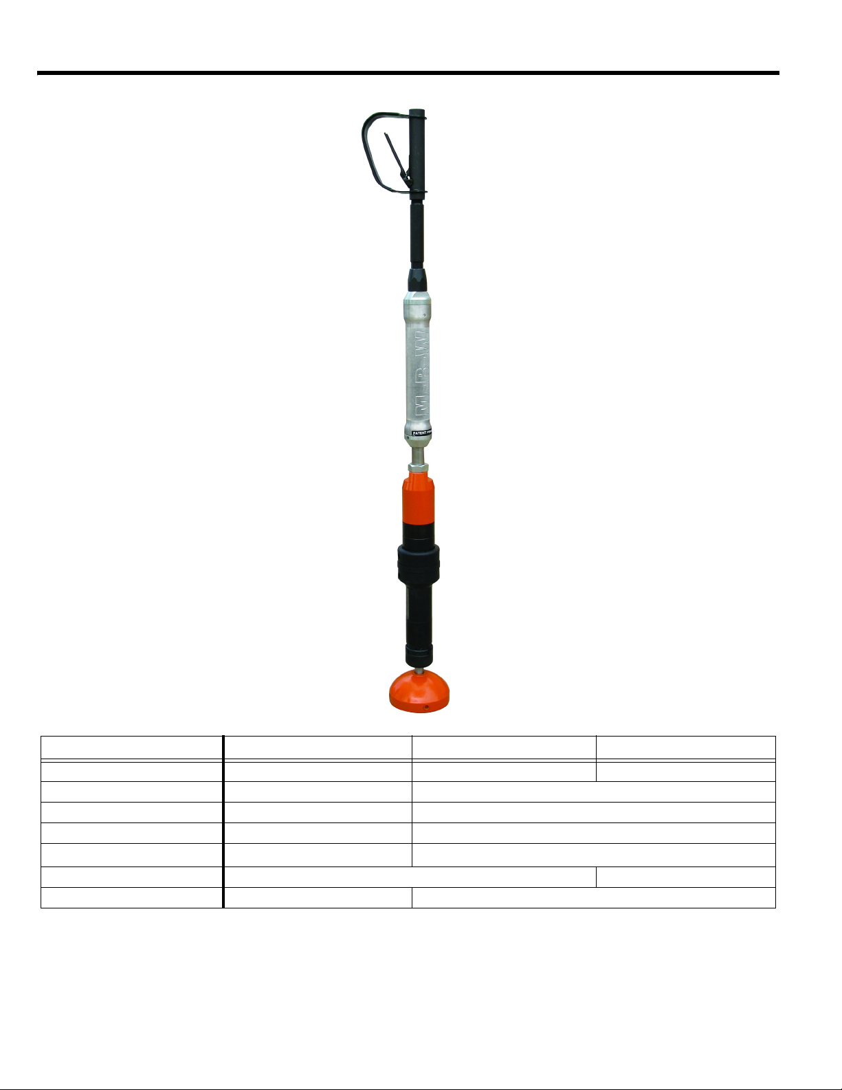
SPECIFICATIONS
VS77 Ergo-Tamp Pole-Tamp
Operating Weight 6.8 lb (3.1 kg) 48 lb (22 kg) 38 lb (17 kg)
Length 17 in (43 cm) 56 in (142 cm)
Foot Diameter -- 6.0 in (15 cm)
Maximum Pressure 140 psi (965 KPa) 90 psi (620 KPa)
Air Consumption --
Vibration Isolation up to 77%* None
Blows per Minute -- 800 @ 90 PSI
Specifications subject to change without notice
* Under ideal conditions, actual vibration isolation may vary with compactor type and compaction conditions
- 2 -
38.5 cfm (1.1 m
3
/m)
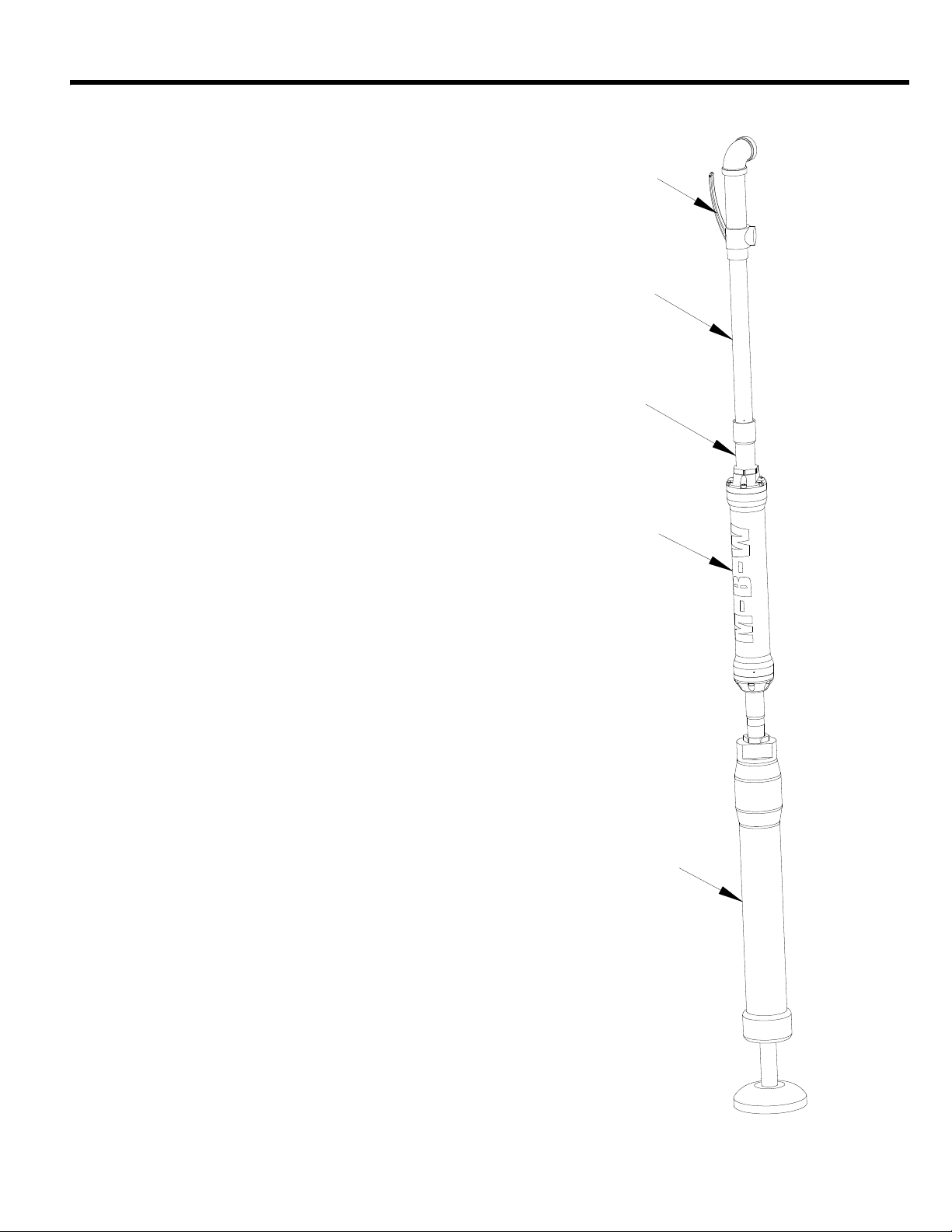
OPERATION
75,**(5
$66(0%/<
(;7(16,21
3,3(
$'$37(5
9,%5$7,21
68335(6625
3(5&866,21
81,7
Introduction
MBW equipment is intended for use in very severe
applications. The Vibration Suppressor is available in a
variety of configurations.
This parts manual contains only standard parts. Variations
of these parts as well as other special parts are not included.
Contact your local MBW distributor for assistance in
identifying parts not included in this manual.
Installation
• The MBW Vibration suppressor is intended to be
installed on a variety of pneumatic pole tampers.
• Connection adapters are included with some models to
add flexibility to installation
1. Disconnect air supply to tool and make sure all air
pressure is released
2. Unscrew connector pipe between trigger assembly
and main percussion unit
3. Attach “ROD” end of the Vibration Suppressor to the
main percussion unit. Tighten connection using a
supplied lock-nut
4. Attach trigger assembly to other end of the Vibration
Suppressor. Tighten connection using a supplied
lock-nut
• Depending on Pole Tamper style, adapters may be
needed to make connections
• To ensure connections stay tight, MBW recommends
using a medium strength thread locker on all
connections
• To lengthen the pole tamper assembly, it is
recommended that the added pipe section be placed
above the Vibration Suppressor
Before Starting & Operating
• REMEMBER! It is the owner’s responsibility to
communicate information on the safe use and proper
operation of this unit to the operators.
• Review ALL of the Safety Precautions listed on page 1 of
this manual.
• Familiarize yourself with the operation of the machine
and confirm that all controls function properly.
• Know how to STOP the machine in case of an
emergency.
- 3 -
• Make sure hands, feet, and clothing are at a safe
WARNING
WARNING
CAUTION
distance from any moving parts.
• The MBW Vibration Suppressor should only be run with
clean and dry compressed air. The use of an oil mist
lubrication system will improve the life of both the
Vibration Suppressor and the pole tamper
• Verify that all joints are tight
Operating Ergo and Pole tamps
Follow all recommended operating procedures of
pole tamper manufacturer. Failure to do so could
result in serious bodily injury or death.
1. Connect air supply hose to trigger assembly
2. Grasp pole tamper assembly on the main body of the
Vibration Suppressor or anywhere above
3. Depress trigger to begin tamping.
4. Release trigger to stop device.
PINCH HAZARD: Avoid placing hands below main
body of the MBW Vibration Suppressor
• The MBW Vibration Suppressor is a spring loaded
device. Efficiency of isolation will depend on many
factors including air pressure, pole tamper type and
operator input. When operating, try to find the correct
down pressure that results in the least amount of
transmitted vibration.
Storage
• The MBW Vibration Suppressor is made of high quality
corrosive resistant components. To lengthen the life of
the entire tamper assembly, drop a small amount of light
oil into trigger assembly and run device for a minute
before long term storage.
Do not place any part of body above pole tamper
assembly. Device will “Jump” when air is
activated.
- 4 -
 Loading...