

Page 1
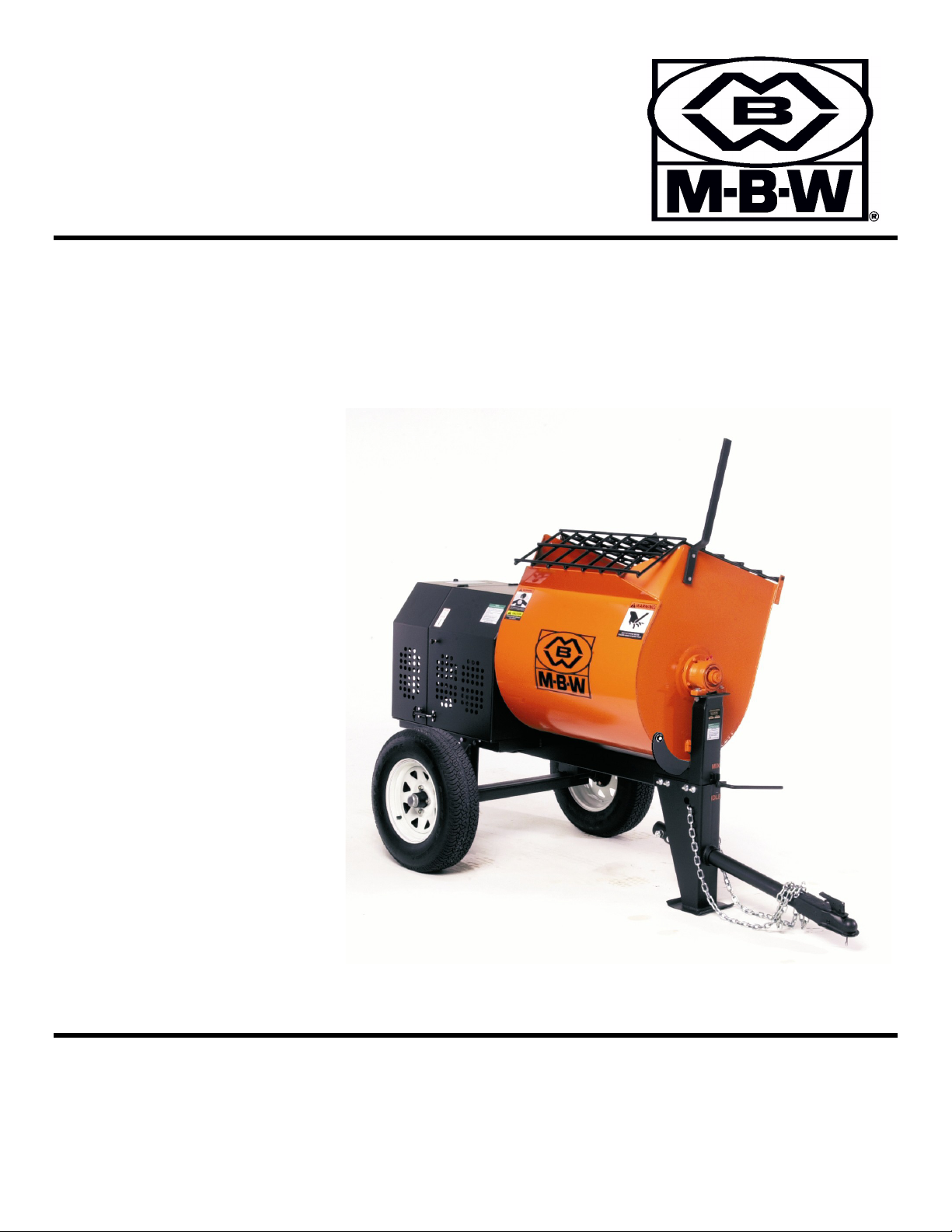
OPERATOR’S SAFETY
AND SERVICE MANUAL
MM60
MM80
MM90
This manual covers the following serial numbers
and higher for each model listed:
MM60 . . . . . . . . . . . . . . . . . . . . 7011600
MM80 . . . . . . . . . . . . . . . . . . . . 7032000
MM90 . . . . . . . . . . . . . . . . . . . . 7051100
MORTAR & PLASTER MIXERS
MBW, Inc.
250 Hartford Rd • PO Box 440
Slinger, WI 53086-0440
Phone: (262) 644-5234
Fax: (262) 644-5169
Email: [email protected]
Website: www.mbw.com
MBW (UK) Ltd.
Units 2 & 3 Cochrane Street
Bolton BL3 6BN, England
Phone: 01204 387784
Fax: 01204 387797
MBW FRANCE S.A.R.L.
Z.A. d’Outreville
11 rue Jean Baptiste Néron,
60540 BORNEL
FRANCE
Phone: +33 (0) 3 44 07 15 96
Fax: +33 (0) 3 44 07 41 28
Email: [email protected]
L16746. 04.14.T
©MBW, Inc. 2005
Printed in the USA
Page 2

TABLE OF CONTENTS
Safety Information . . . . . . . . . . . . . . . . . . . . . . 1
Introduction . . . . . . . . . . . . . . . . . . . . . . . . . . . . . . . . . 1
Safety Precautions . . . . . . . . . . . . . . . . . . . . . . . . . . . 1
Safety Decals . . . . . . . . . . . . . . . . . . . . . . . . . . . . . . . 1
Specifications. . . . . . . . . . . . . . . . . . . . . . . . . . 5
Operation . . . . . . . . . . . . . . . . . . . . . . . . . . . . . 6
Introduction . . . . . . . . . . . . . . . . . . . . . . . . . . . . . . . . . 6
Before Starting & Operating . . . . . . . . . . . . . . . . . . . . 6
Wiring Electric Motor. . . . . . . . . . . . . . . . . . . . . . . . . . 6
Starting Gas Engine . . . . . . . . . . . . . . . . . . . . . . . . . . 6
Starting Electric Motor . . . . . . . . . . . . . . . . . . . . . . . . 6
Operating . . . . . . . . . . . . . . . . . . . . . . . . . . . . . . . . . . 6
Stopping Gas Engine . . . . . . . . . . . . . . . . . . . . . . . . . 6
Stopping Electric Motor. . . . . . . . . . . . . . . . . . . . . . . . 7
Towing . . . . . . . . . . . . . . . . . . . . . . . . . . . . . . . . . . . . 7
Maintenance . . . . . . . . . . . . . . . . . . . . . . . . . . . 8
Maintenance Schedule . . . . . . . . . . . . . . . . . . . . . . . . 8
Engine Maintenance . . . . . . . . . . . . . . . . . . . . . . . . . . 8
Engine Speed . . . . . . . . . . . . . . . . . . . . . . . . . . . . . . . 8
Cleaning . . . . . . . . . . . . . . . . . . . . . . . . . . . . . . . . . . . 8
Lubrication . . . . . . . . . . . . . . . . . . . . . . . . . . . . . . . . . 8
Belt Guides. . . . . . . . . . . . . . . . . . . . . . . . . . . . . . . . . 9
Greasing Wheel Bearings . . . . . . . . . . . . . . . . . . . . . 9
Service. . . . . . . . . . . . . . . . . . . . . . . . . . . . . . . 10
Engine Shroud Removal . . . . . . . . . . . . . . . . . . . . . 10
Engine Shroud Installation . . . . . . . . . . . . . . . . . . . . 10
Drum Removal . . . . . . . . . . . . . . . . . . . . . . . . . . . . . 10
Drum Installation . . . . . . . . . . . . . . . . . . . . . . . . . . . 10
Drum Bearing & Seals Replacement . . . . . . . . . . . . 11
Engine Removal . . . . . . . . . . . . . . . . . . . . . . . . . . . . 11
Engine Installation . . . . . . . . . . . . . . . . . . . . . . . . . . 11
Parts Replacement Cycles and Tolerances . . . . . . . 12
Replacement Parts . . . . . . . . . . . . . . . . . . . . . 13
Drum Assembly . . . . . . . . . . . . . . . . . . . . . . . . . . . . 14
Drivetrain Assembly . . . . . . . . . . . . . . . . . . . . . . . . . 16
Electric Motor Drivetrain Assembly . . . . . . . . . . . . . 18
Idler Assembly . . . . . . . . . . . . . . . . . . . . . . . . . . . . . 20
Air Mixer Assembly. . . . . . . . . . . . . . . . . . . . . . . . . . 22
Frame & Axle Assembly . . . . . . . . . . . . . . . . . . . . . . 24
Paddle Assembly . . . . . . . . . . . . . . . . . . . . . . . . . . . 26
Warranty . . . . . . . . . . . . . . . . . . . . . . . . . . . . . 28
Page 3
CALIFORNIA PROPOSITION 65 WARNING
WARNING
Engine exhaust and some of its constituents are
known in the state of California to cause cancer, birth
defects, and other reproductive harm.
Page 4
SAFETY INFORMATION
WARNING
CAUTION
Introduction
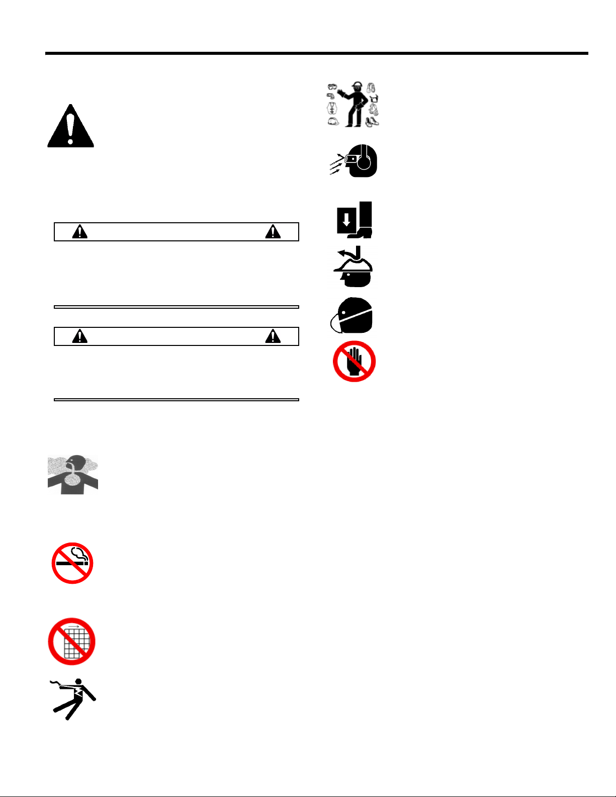
This Safety Alert Symbol is used to call attention
to items or operations which may be dangerous
to those operating or working with this
equipment. The symbol can be found
throughout this manual and on the unit. Please read these
warnings and cautions, along with all decals, carefully
before attempting to operate the unit. Make sure every
individual who operates or works with this equipment is
familiar with all safety precautions.
GENERAL WARNING. Indicates information
important to the proper operation of the
equipment. Failure to observe may result in
damage to the equipment and/or severe bodily
injury or death.
GENERAL CAUTION. Indicates information
important to the proper operation of the
equipment. Failure to observe may result in
damage to the equipment.
Safety Precautions
LETHAL EXHAUST GAS: An internal
combustion engine discharges carbon
monoxide, a poisonous, odorless, invisible
gas. Death or serious illness may result if
inhaled. Operate only in an area with proper
ventilation. NEVER OPERATE IN A
CONFINED AREA!
DANGEROUS FUELS: Use extreme caution
when storing, handling and using fuels, as
they are highly volatile and explosive in vapor
state. Do not add fuel while engine is running.
Stop and cool the engine before adding fuel.
DO NOT SMOKE!
SAFETY GUARDS: It is the owner's
responsibility to ensure that all guards and
shields are in place and in working order.
IGNITION SYSTEMS: Breakerless, magneto,
and battery ignition systems can cause severe
electrical shocks. Avoid contacting these
units or their wiring.
SAFE DRESS: Do not wear loose clothing,
rings, wristwatches, etc. near machinery.
NOISE PROTECTION: Wear OSHA specified
hearing protection devices.
EYE PROTECTION: Wear OSHA specified
eye shields, safety glasses, and sweat bands.
FOOT PROTECTION: Wear OSHA specified
steel-tipped safety shoes.
HEAD PROTECTION: Wear OSHA specified
safety helmets.
DUST PROTECTION: Wear OSHA specified
dust mask or respirator.
OPERATOR: Keep children and bystanders
off and away from the equipment.
REFERENCES: For details on safety rules and regulations
in the United States, contact your local Occupational Safety
and Health Administration (OSHA) office. Equipment
operated in other countries must be operated and serviced
in accordance and compliance with any and all safety
requirements of that country. The publication of these
safety precautions is done for your information. MBW does
not by the publication of these precautions, imply or in any
way represent that these are the sum of all dangers present
near MBW equipment. If you are operating MBW
equipment, it is your responsibility to insure that such
operation is in full accordance with all applicable safety
requirements and codes. All requirements of the United
States Federal Occupational Safety and Health
Administration Act must be met when operated in areas that
are under the jurisdiction of that United States Department.
Safety Decals
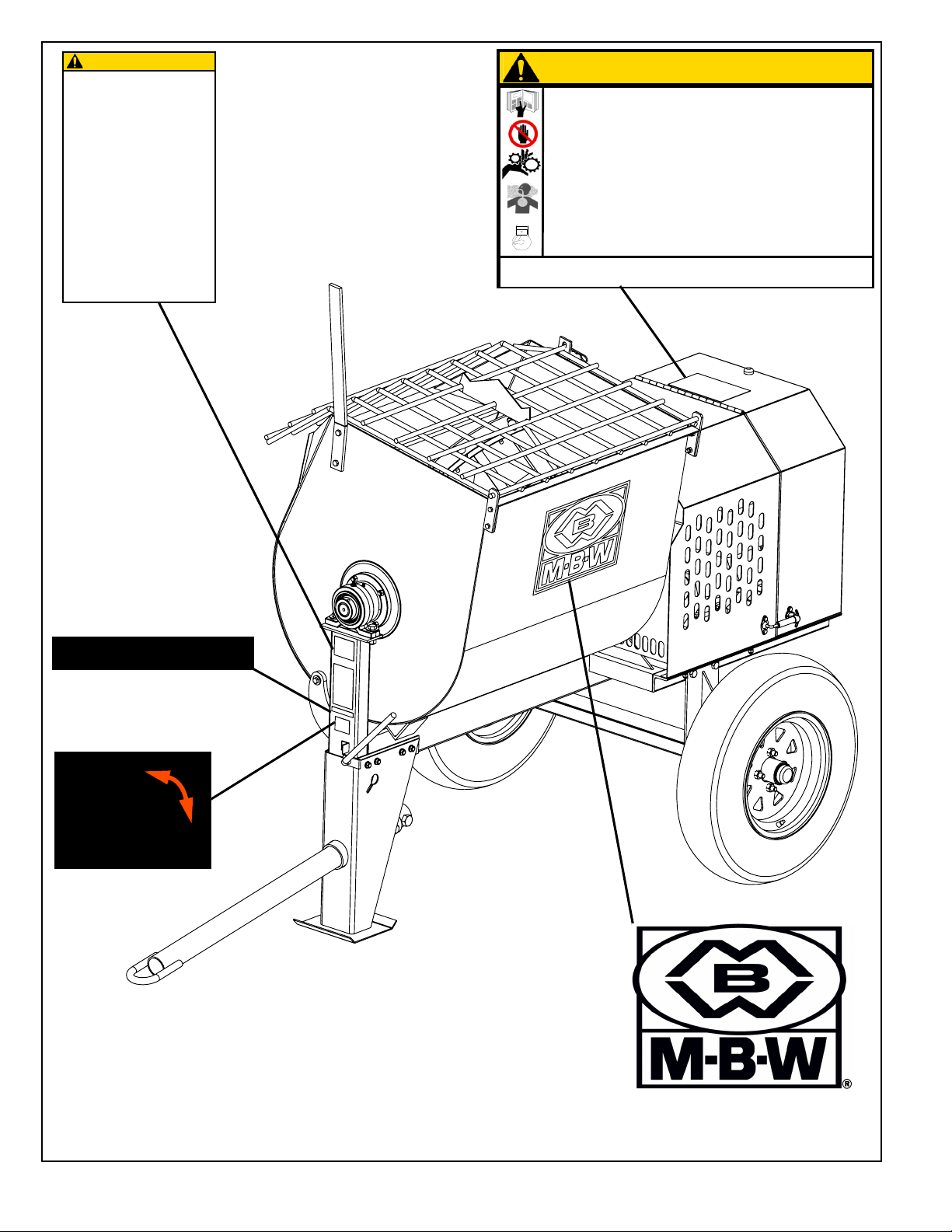
Carefully read and follow all safety decals. Keep them in
good condition. If decals become damaged, replace as
required. If repainting the unit, replace all decals. Decals
are available from authorized MBW distributors. Order the
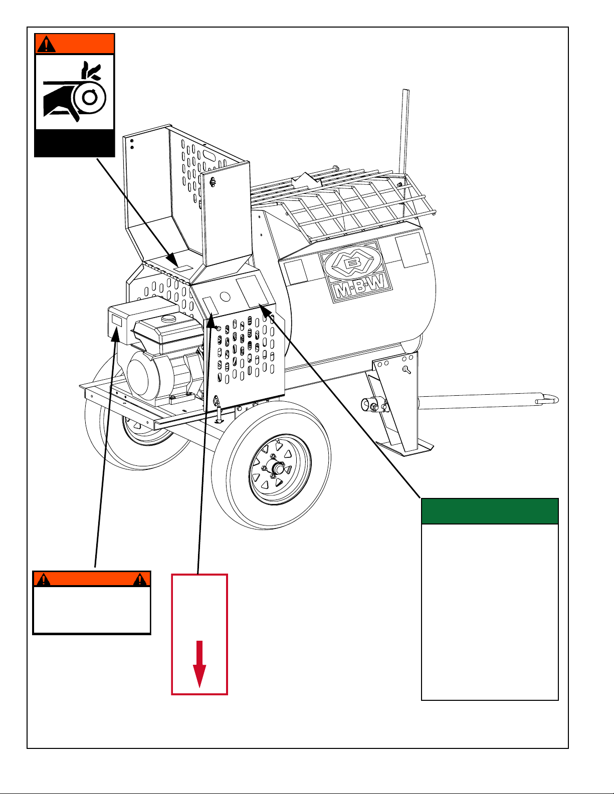
decal set listed on the following page(s).
- 1 -
Page 5
U.S. PATENT 6,695,467
17949
Before Towing:
1. Check running gear and tow bar.
2. Lock drum in tow position.
3. Check tow pin for proper instal-lation
and good condition.
4. USE SAFETY CHAINS when towing.
MAXIMUM TOW SPEED: 50 mph
Improper towing can lead to
damage or injury.
CAUTION(PRECAUCIÓN)
15072
Un remolque incorrecto
puede provocar daños
materiales o lesiones.
Antes del remolque:
1. Revise el funcionamiento de los
engranajes y de la barra de remolque.
2. Bloquee el tambor en la posición de
remolque.
3. Verifique que el pasador de remolque
esté bien instalado y en buen estado.
4. USE CADENAS DE SEGURIDAD al
remolcar la máquina.
MÁX. VELOCIDAD DE REMOLQUE:
80 KPH
STOP
CAUTION(PRECAUCIÓN)
15070
Failure to comply could result in serious bodily injury
El no cumplir con estas instrucciones puede producir como resultado lesiones corporales graves.
Read the operating instructions before operating this piece of equipment.
Lea las Instrucciones Operativas antes de hacer funcionar esta parte del equipo.
Keep unauthorized, inexperienced, untrained people away from this equipment.
Mantenga a las personas no autorizadas y sin entrenamiento alejadas de este equipo.
ROTATING AND MOVING PARTS! Make sure all guards and safety devices are in
place.
¡HAY PIEZAS ROTATIVAS Y MÓVILES! Asegúrese de que todas las guardas y
dispositivos de seguridad estén colocados en sus lugares.
DO NOT RUN this machine in an exnclosed area. The engine produces carbon
monoxide, a POISONOUS gas.
NO HAGA FUNCIONAR esta máquina en una zona encerrada. El motor produce
monóxido de carbono, un GAS VENENOSO.
SHUT OFF the engine before servicing, cleaning or adding fuel to engine or machine.
APAQUE el motor antes de hacerle el servicio, limiarlo o agregarle combustible.
MI
X
IDLE
17129
RALENTÍ
MEZCLA
15072
17949 - Not included
with decal set
15070
17129
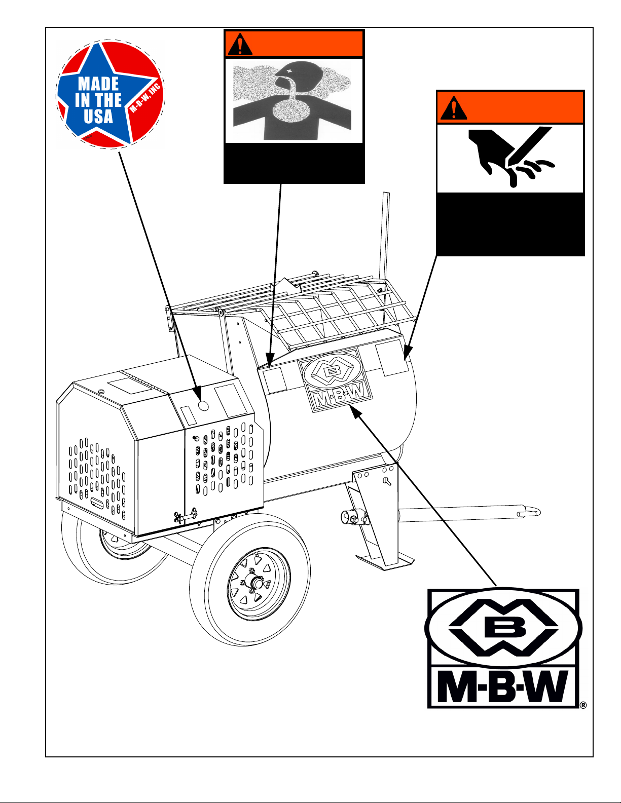
Safety Decals (Decal Set #15074)
01554 - Not included
with decal set
- 2 -
Page 6
WARNING
ENGINE EXHAUST IS HAZARDOUS IF INHALED
USE ONLY IN A WELL VENTILATED AREA
15076
EL GAS DEL ESCAPE DEL MOTOR ES
PELIGROSO SI SE INHALA
USE LA MÁQUINA SÓLO EN UNA ZONA BIEN
VENTILADA
ADVERTENCIA
WARNING
LAS PIEZAS MÓVILES PUEDEN IMPACTAR Y CORTAR
¡MANTENGA ALEJADAS SUS MANOS!
APAGUE EL MOTOR ANTES DEL SERVICIO.
15069
MOVING PARTS CAN CRUSH AND CUT
KEEP HANDS CLEAR!
SHUT OFF ENGINE OR MOTOR
BEFORE SERVICING.
ADVERTENCIA
12500
15076
15069
Safety Decals (Decal Set #15074)
01554 - Not included with decal set
- 3 -
Page 7
MIXER(MEZCLADORA)
OPERATING INSTRUCTIONS
1. Check oil in engine crankcase.
2. MAKE SURE grid is CLOSED before starting and during operation.
3. Place engage lever in IDLE position before starting engine.
4. Open fuel valve.
5. Close choke on engine. A warm engine may not need to be choked.
6. Open throttle to FAST position.
7. Pull starter rope.
8. After starting, turn choke off, let engine warm up at idle.
9. Open throttle to FAST position, CLOSE SHROUD! Place
engagement lever in MIX position, charge mixer.
10. TO STOP: Place engagement lever in IDLE position, return throttle
to idle, close fuel valve, press stop button.
11. Before towing, check that drum is locked in towing position, and tow
pin is properly installed and in good condition.
MAXIMUM TOW SPEED: 50 MPH
MÁX. VELOCIDAD DE REMOLQUE: 80 KPH
15071
INSTRUCCIONES DE OPERACIÓN
1. Revise el aceite en el cárter del motor.
2. CERCIÓRESE de que la rejilla esté CERRADA antes del arranque y durante la
operación.
3. Coloque la palanca de engranaje en la posición de RALENTÍ antes de arrancar
el motor.
4. Abra la válvula de combustible.
5. Cierre el estrangulador del motor. Si el motor está tibio, puede que no requiera
estrangulamiento.
6. Abra el acelerador a la posición RÁPIDA.
7. Tire de la cuerda de arranque.
8. Tras el arranque, apague el estrangulador y deje que el motor se caliente en
ralentí.
9. Abra el acelerador y póngalo en la posición RÁPIDA, ¡CIERRE LA CUBIERTA!
Coloque la palanca de engranaje en la posición de MEZCLA, cargue la
mezcladora.
10. PARA DETENERLA: Coloque la palanca de engranaje en la posición RALENTÍ,
vuelva el acelerador a ralentí, cierre la válvula de combustible y pulse el botón de
parada.
11. Antes del remolque, verifique que el tambor esté bloqueado en la posición de
remolque, y que el perno esté correctamente instalado y en buen estado.
PUSH
TO
STOP
16546
PULSE PARA
DETENER
12573
19791
WARNING
OPERATION OF THIS EQUIPMENT MAY
CREATE SPARKS THAT CAN START FIRES
AROUND DRY VEGETATION. A SPARK
ARRESTER MAY BE REQUIRED. THE
OPERATOR SHOULD CONTACT LOCAL FIRE
AGENCIES FOR LAWS OR REGULATIONS
RELATING TO FIRE PREVENTION
19791
Safety Decals (Decal Set #15074)
16546
15071
- 4 -
Page 8
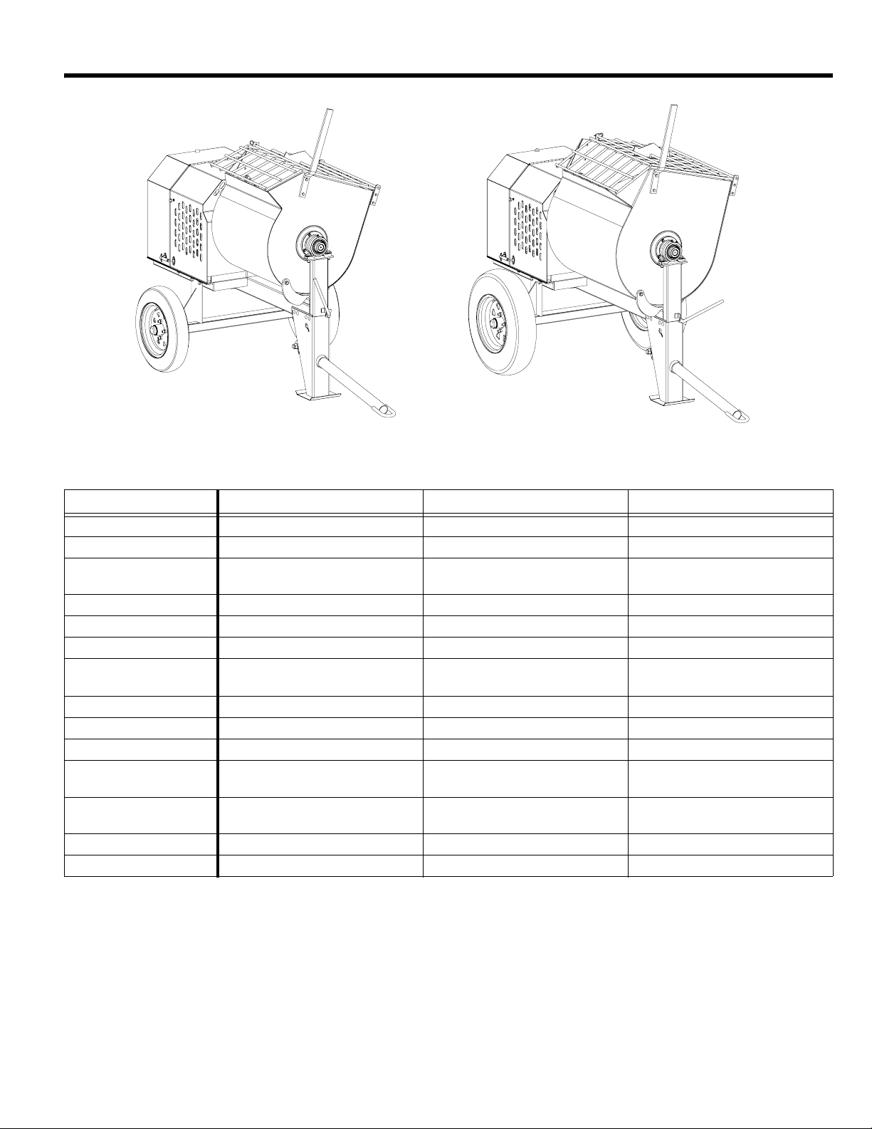
SPECIFICATIONS
MM90
MM60
MM60 MM80 MM90
Batch Capacity 6 cu. ft (.17 cu. m) 8 cu. ft (0.23 cu. m) 9 cu. ft (0.26 cu. m)
Batch Size 2 bags 2.5 - 3 bags 3 - 3.5 bags
Gas Engines
Engine Speed 3500 rpm 3300 rpm 3300 rpm
Drivetrain V-belts to Gears V-belts to Gears V-belts to Gears
Electric Motors Baldor 1.5 hp (1-phase) Baldor 2 hp (1-phase) Baldor 3 hp (1-phase)
Motor Draw
Motor Speed 1725 rpm 1725 rpm 1725 rpm
Drivetrain Chain to V-belts to Gears Chain to V-belts to Gears Chain to V-belts to Gears
Axle 46” Solid Axle 46” Solid Axle 46” Solid Axle
Wheels
Size - W x L x H
Weight 650 lbs (295 kg) 715 lbs (324 kg) 730 lbs (331 kg)
Charging Height 47 in (119 cm) 49 in (124 cm) 49 in (124 cm)
Specifications subject to change without notice
Honda GX160
Honda GX240
115V - 18A
230V - 9A
4.80 x 12
High-Speed
46 x 64 x 56 in
(117 x 163 x 142 cm)
Honda GX240 Honda GX240
230V - 14A 230V - 15.5A
ST175/80D13
High-Speed
46 x 67 x 57 in
(117 x 170 x 145 cm)
ST175/80D13
High-Speed
46 x 71 x 57 in
(117 x 180 x 145 cm)
- 5 -
Page 9
OPERATION
WARNING
WARNING
CAUTION
Introduction
MBW equipment is intended for use in very severe
applications. They are powered by four cycle engines and
are available in different sizes and a selection of engines.
This parts manual contains only standard parts. Variations
of these parts as well as other special parts are not included.
Contact your local MBW distributor for assistance in
identifying parts not included in this manual.
Before Starting & Operating
• REMEMBER! It is the owner’s responsibility to
communicate information on the safe use and proper
operation of this unit to the operators.
• Review ALL of the Safety Precautions listed on page 1 of
this manual.
• Familiarize yourself with the operation of the machine
and confirm that all controls function properly.
• Know how to STOP the machine in case of an
emergency.
• Make sure hands, feet, and clothing are at a safe
distance from any moving parts.
• OIL LEVEL - Check the oil level in the engine. For more
information see “Lubrication” under the respective
engine’s “Owners Manual” or the Maintenance section of
this manual.
• AIR CLEANER - Check to ensure element is in good
condition and properly installed.
• FUEL SUPPLY - The engines on MBW equipment
require an automotive grade of clean, fresh, unleaded
gasoline.
• FUEL FILTER - If clogged or damaged, replace.
Wiring Electric Motor
3. Pull out the stop switch on the engine shroud.
4. Move the engine throttle lever to the “FAST” position.
5. Choke the engine if necessary. (You may not need to
choke a warm engine).
6. Pull the starter rope repeatedly until engine starts.
7. Move choke lever to open position and throttle lever
to the “IDLE” position
8. Allow engine to warm up for one or two minutes.
Starting Electric Motor
1. Move mixer engagement lever to “IDLE” position.
2. Plug the motor into a suitable power source.
3. Move the switch on the motor to the “ON” position.
Operating
1. Close the engine shroud.
Do not operate the mixer with the shroud open.
2. Move engagement lever to the “MIX” position.
3. Add half of the required amount of sand and water for
the batch to be mixed.
4. Add the total required amount of mortar mix.
5. Add the remaining amounts of sand and water and allow time to mix properly.
6. Unlock the drum by rotating the locking bar out of engagement with the frame.
7. Tip the drum forward to discharge the batch.
8. Return drum to mixing position and check that it is
locked in place.
9. If another batch is to be mixed, add water for the next
batch.
All electric motors come with a 12” pigtail which must be
wired with a plug for your application.
Wiring must be done by certified electrician.
Starting Gas Engine
1. Move mixer engagement lever to “IDLE” position.
2. Open the fuel valve.
Always clean the drum after each day’s operation.
See Cleaning, page 8.
Stopping Gas Engine
1. Move mixer engagement lever to the “IDLE” position.
2. Whenever possible it is recommended to let the engine idle before stopping.
3. Push in the engine stop switch on the engine shroud.
- 6 -
Page 10
4. Close the fuel valve.
WARNING
WARNING
Stopping Electric Motor
1. Move mixer engagement lever to the “IDLE” position.
2. Move the switch on the motor to the “OFF” position.
Always STOP the engine before adding fuel.
Always STOP the engine or motor before leaving
the equipment unattended for any amount of time.
Always STOP the engine or motor and disconnect
spark plug wire or power cord before making any
repairs or adjustments to the machine.
Towing
1. Stop the engine or electric motor.
2. Close and latch the engine shroud.
3. Rotate the drum into the locked position, and check
that it is locked in place.
4. Secure the mixer hitch and safety chains to the vehicle.
Always check that axle, front leg, and tow bar
hardware is tight before towing.
Make sure safety bolt is in place.
Check the condition of the pin on the tow bar and
make sure it is secure.
Remove any loose debris from the mixer before
towing on roads.
Check that safety chains cross each other when
attached.
MAXIMUM TOW SPEED: 50 mph
- 7 -
Page 11
MAINTENANCE
WARNING
CAUTION
CAUTION
WARNING
Always exercise the stopping procedure before
servicing or lubricating the unit.
After servicing the unit, replace and fasten all
guards, shields, and covers to their original
positions before resuming operation.
Always verify fluid levels and check for leaks after
changing fluids.
Do not drain oil onto ground, into open streams,
or down sewage drains.
Maintenance Schedule
SYSTEM MAINTENANCE EACH USE
Axle Check tire pressure X
Grease wheel bearings X
Drivetrain Inspect drive belts for excessive wear X
Oil electric motor drive chain X
Grease bull gear teeth X
Drum Grease trunnions & pillow blocks X
Engine Refer to engine operator/owner manual X
Hardware
Check and tighten all hardware
1,2
EVERY 40
HOURS
EVERY 100
HOURS
YEARLY
X
1. Check all hardware after the first 5 hours of use, then follow the maintenance schedule.
2. Retorque lug nuts, front leg, and axle hardware after the first 25 miles traveled, then follow the maintenance schedule.
Engine Maintenance
Refer to the engine owner’s manual for maintenance
intervals and procedures.
Always stop engine or motor and disconnect
spark plug wire or power cord before placing
hands or objects inside drum.
Engine Speed
Always reconnect safety grid opener to grid after
Engine speed is factory set according to the speeds listed in
the Specifications section of this manual. Refer to the engine owner’s manual for procedure on setting operating
speed if necessary.
Cleaning
Always clean the mixer thoroughly after each day’s
operation. Dried mortar inside the drum can damage the
paddles and shorten the life of the mixer. Additionally, future
batches of mortar can be contaminated if the drum is not
clean.
cleaning drum.
Lubrication
1. Grease both trunnions and pillow blocks daily. There
are two grease fittings on each end of the drum.
2. Apply a light coat of grease to the gear teeth once a
month.
3. Oil all pivot points on the idler assembly once a week.
4. Electric mixers: Oil the drive chain once a week.
Do not beat on the drum to clean dried mortar;
this will cause damage to the drum.
- 8 -
Page 12
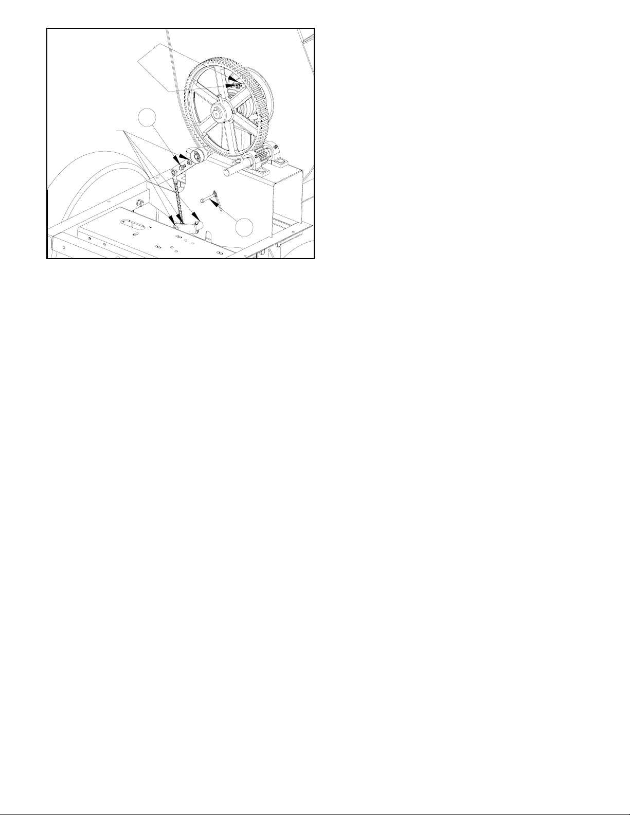
Belt Guides
GREASE DAILY
OIL WEEKLY
2
1
FIGURE 1
Greasing Wheel Bearings
1. Jack the rear end of the mixer and support by side
rails so that mixer is stable.
2. Remove the wheel.
3. Remove the dust cover.
4. Remove the cotter pin from the spindle nut.
5. Unscrew the spindle nut.
6. Remove the hub from the spindle, being careful not
to allow the outer bearing cone to fall out. The inner
bearing cone will be retained by the seal.
7. Remove the grease seal.
8. Wash all grease and oil from the bearing cones and
inspect each roller. If any pitting, spalling, or
corrosion is present, then the bearing cup and cone
must be replaced.
9. Pack the entire bearing with grease, apply a light coat
of grease to the bearing cup, and install.
Belt driven models are equipped with guides to ensure proper operation. If the paddles do not stop when in the “IDLE”
position, follow these steps to adjust them.
1. With engine stopped, move the engagement lever to
the “MIX” position.
2. Loosen the nuts on the 3-1/4” long bolt (Figure 1, #1)
below the drive belts. Move the bolt to within 1/16” of
the belts and retighten the nuts.
3. Loosen nut on the 3/4” long bolt (Figure 1, #2) located
in the slot on the idler arm.
4. Move engagement handle to “IDLE” position and
start engine.
5. Move engagement handle towards “MIX” position until belts stop moving.
6. Slide 3/4” bolt and nut until they contact the edge of
the frame and tighten.
10. Tap a new grease seal into place with a clean block.
11. Slide the hub onto the spindle.
12. While rotating the hub slowly, tighten the spindle nut
to approximately 50 lb-ft.
13. Loosen the spindle nut, but DO NOT rotate the hub.
14. Finger tighten the spindle nut until snug.
15. Back the spindle nut out slightly until the first
castellation lines up with the cotter pin hole and insert
the cotter pin.
16. Bend over the cotter pin legs to secure the nut.
17. Tap the dust cover into the hub.
18. Install wheel and torque lug nuts to 90 lb-ft.
- 9 -
Page 13
SERVICE
Assembly and disassembly should be performed by a
service technician who has been factory trained on MBW
equipment. The unit should be clean and free of debris.
Pressure washing before disassembly is recommended.
• Prior to assembly, wash all parts in a suitable cleaner or
solvent.
• Check moving parts for wear and failure. Refer to the
Replacement section in this manual for tolerance and
replacement cycles.
• All shafts and housings should be oiled prior to pressing
bearings. Also, ensure that the bearings are pressed
square and are seated properly.
• All gaskets and seals should be replaced after any
disassembly.
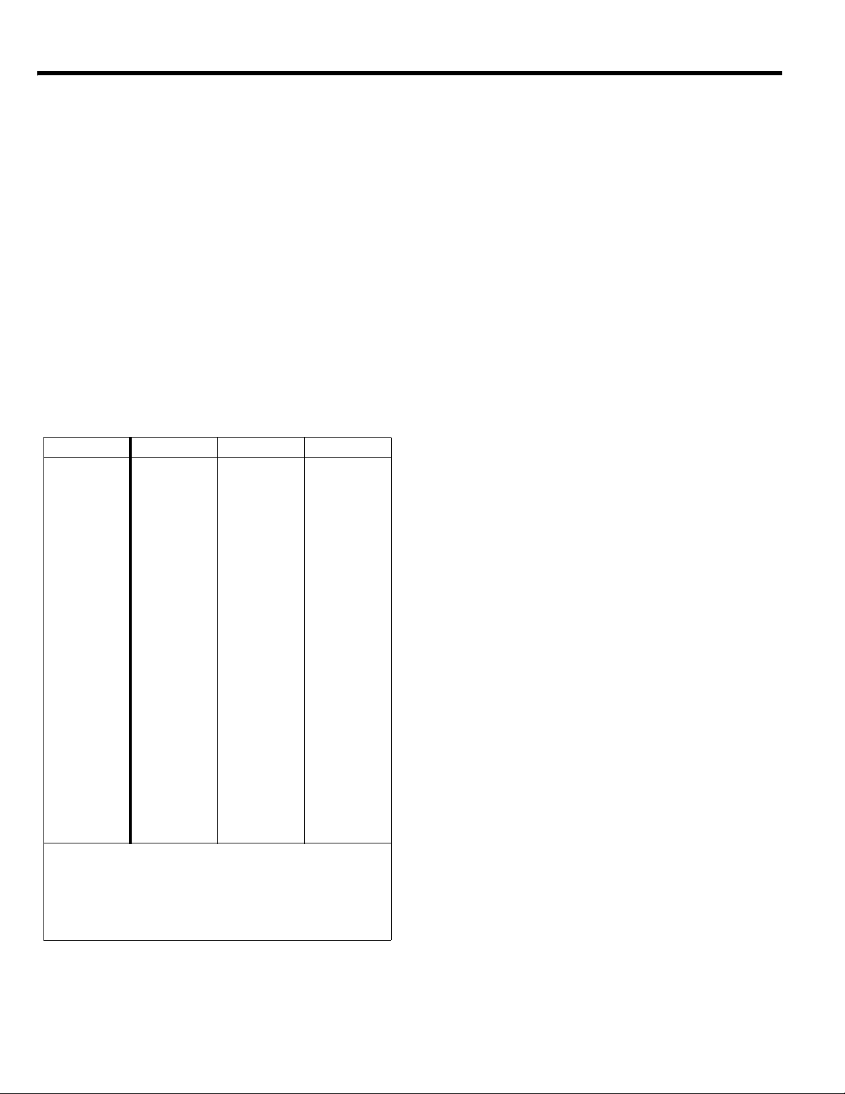
Torque Chart
SIZE GRADE 2 GRADE 5 GRADE 8
1/4-20 49 in
1/4-28 56 in
5/16-18 8 ft
5/16-24 9 ft
3/8-16 15 ft
3/8-24 17 ft
7/16-14 24 ft
7/16-20 27 ft
1/2-13 37 ft
1/2-20 41 ft
9/16-12 53 ft
5/8-11 73 ft
5/8-18 83 ft
3/4-16 144 ft
1-8 188 ft
1-14 210 ft
1-1/2-6 652 ft
M 6 3 ft
M 8 6 ft
M 10 10 ft
•lbs 76 in•lbs 9 ft•lbs
•lbs 87 in•lbs 10 ft•lbs
•lbs 13 ft•lbs 18 ft•lbs
•lbs 14 ft•lbs 20 ft•lbs
•lbs 23 ft•lbs 33 ft•lbs
•lbs 26 ft•lbs 37 ft•lbs
•lbs 37 ft•lbs 52 ft•lbs
•lbs 41 ft•lbs 58 ft•lbs
•lbs 57 ft•lbs 80 ft•lbs
•lbs 64 ft•lbs 90 ft•lbs
•lbs 82 ft•lbs 115 ft•lbs
•lbs 112 ft•lbs 159 ft•lbs
•lbs 112 ft•lbs 180 ft•lbs
•lbs 200 ft•lbs 315 ft•lbs
•lbs 483 ft•lbs 682 ft•lbs
•lbs 541 ft•lbs 764 ft•lbs
•lbs 1462 ft•lbs 2371 ft•lbs
•lbs 4 ft•lbs 7 ft•lbs
•lbs 10 ft•lbs 18 ft•lbs
•lbs 20 ft•lbs 30 ft•lbs
CONVERSIONS
•lbs x 0.083 = ft•lbs
in
•lbs x 12 = in•lbs
ft
•lbs x 0.1383 = kg•m
ft
•lbs x 1.3558 = N•m
ft
Engine Shroud Removal
Refer to Drivetrain Assembly, page 16.
1. Disconnect wiring harness (#18) from engine by unscrewing ring terminal from engine and unplugging
bullet connector.
2. Remove automatic safety grid lifter from safety grid.
3. Remove four bolts (#25), washers (#27), and locknuts (#26) securing shroud to frame.
4. Carefully lift shroud straight up to avoiding damaging
engine or drive components. Approximate weight is
85 pounds.
Engine Shroud Installation
Refer to Drivetrain Assembly, page 16.
1. Lift shroud over engine and drive components and
lower it straight down onto frame. Hold grid opener
out of the way while lowering.
2. Align shroud with edges of frame and tighten bolts
(#25), washers (#27), and locknuts (#26) in place.
3. Lift grid opener into position and pin to safety grid.
4. Connect wiring harness (#18) to engine by grounding
the ring terminal to the engine and inserting the bullet
connector into the splice terminal.
Drum Removal
Refer to Drum Assembly, page 14.
1. Remove engine shroud before attemping to remove
mixing drum.
2. Mark the front and rear pillow block (#5) locations on
the frame to aid in the alignment during installation.
3. Remove all four bolts (#25), washers (#28 & #10),
lockwashers (#27), and locknuts (#26) holding drum
pillow blocks to frame.
4. If lifting drum by hoist, wrap chain around main shaft
and pass chain through paddles to stabilize. If lifting
drum by forklift, place blocks on forks to prevent drum
from rolling. Approximate weight is 250 to 300
pounds, depending on model.
Drum Installation
Refer to Drum Assembly, page 14.
1. Lower drum onto frame supports. Pillow blocks (#5)
should be snug to trunnions (#8) to eliminate
excessive endplay.
- 10 -
Page 14

2. Check alignment between bull gear and pinion.
Gears must be parallel and in-line. Adjust drum location if necessary.
3. Bolt pillow blocks to frame using four bolts (#25),
washers (#28 & #10), lockwashers (#27), and locknuts (#26).
4. Dump drum to check for binding. If binding is noticed,
loosen bolts and realign pillow blocks.
5. Loosen intermediate shaft bolts and fine tune gear
alignment if necessary. Set backlash in gears to
0.010” before tightening. NOTE: It may be necessary
to re-adjust alignment of drum or engine so that both
sheaves line up properly.
6. Reinstall the engine shroud.
Drum Bearing & Seals Replacement
Refer to Drum Assembly, page 14.
1. Remove mixing drum from mixer. See Drum
Removal, page 10.
2. Loosen set screws and remove bull gear from main
shaft. Use a puller if necessary.
3. Slide pillow blocks (#5) off of trunnions (#8).
4. Loosen set screw and remove locking collars from
trunnion bearings (#4) by rotating the collars against
the mixing direction of the paddles.
5. Remove four bolts (#19) and nuts (#22) holding each
trunnion to the drum.
6. While supporting the main shaft, slide the trunnion off
of each end.
7. Pull the triple seal kit (#9) out of the back side of each
trunnion and discard.
8. Remove the retaining ring (#7) from each trunnion.
9. Remove the ball bearing and grease shield (steel
washer) from the front side of each trunnion.
10. Inspect the bearings, and replace both if needed.
11. Thoroughly clean all grease from the trunnions.
12. Apply a medium strength thread locking compound to
each outer bearing surface and reinstall the bearings
and grease shields into the trunnions.
13. Reinstall the retaining rings.
14. Install new seal kits into the back side of each
trunnion in the following order: Steel Washer, Soft
Black Seal, Steel Washer, Soft Black Seal, Steel
Washer, Hard Red Seal.
15. Slide trunnions onto each shaft end and bolt in place.
16. Slide bearing locking collar onto front shaft end and
align shaft flush with collar.
17. Lock collar in place by driving in the mixing direction.
18. Tighten set screw using a medium strength thread
locking compound and torque to 20 ft. lbs.
19. Repeat process for rear bearing.
20. Begin pumping grease into trunnion cavity while
rotating main shaft back and forth. NOTE: If grease
comes out through ball bearing seals, check that
grease shield (steel washer) is installed and that
bearing is fully seated in trunnion and cannot move.
21. Continue pumping grease until drum seals “pop out”
into drum. Clean any excess grease from inside
drum.
22. Slide pillow blocks onto trunnions and grease until a
film of grease is seen all around the trunnion.
23. Reinstall the bull gear. Tighten set screws using a
medium strength thread locking compound.
24. Reinstall mixing drum onto frame. See Drum
Installation, page 10.
Engine Removal
Refer to Drivetrain Assembly, page 16.
1. Disengage mixer by moving engagement handle to
“IDLE” position.
2. Disconnect wiring harness (#18) from engine by unscrewing ring terminal from engine and unplugging
bullet connector.
3. Remove four bolts, washers, lockwashers, and nuts
holding engine to frame.
4. Tilt engine and remove drive belts.
5. Lift engine off of frame.
Engine Installation
Refer to Drivetrain Assembly, page 16.
1. Set engine onto frame and line up with holes.
2. Disengage idler by moving engagement handle to
“IDLE” position and install both drive belts.
3. Install four bolts, washers, lockwashers, and nuts to
secure engine. Check for proper alignment between
both sheaves (#4 & #5) with a straightedge before
tightening hardware.
4. Connect wiring harness (#18) to engine by grounding
the ring terminal to the engine and inserting the bullet
connector into the splice terminal.
- 11 -
Page 15

Parts Replacement Cycles and Tolerances
Bearings
Clutch Replace clutch if it does not disengage below 1800 rpm.
Engine Components Refer to your engine manufacturer’s Owner’s Manual.
Hardware
Safety Decals Replace if they become damaged or illegible.
Seals & Gaskets Replace if a leak is detected and at every overhaul or teardown.
V-Belts Replace if cracked, torn, or stretched to the point the belt won’t tension properly.
Replace anytime a bearing is rough, binding, discolored or removed from housing or
shaft.
Replace any worn or damaged hardware as needed. Replacement hardware should
be grade 5 and zinc plated unless otherwise specified.
- 12 -
Page 16
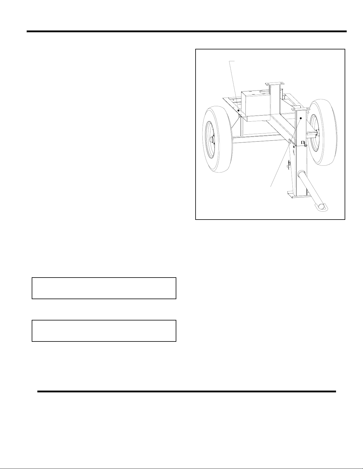
REPLACEMENT PARTS
Write Model Number here
Write Serial Number here
The warranty is stated in this book on page 28. Failure to
return the Warranty Registration Card renders the warranty
null and void.
MBW, Inc. has established a network of reputable distributors with trained mechanics and full facilities for maintenance and rebuilding, and to carry an adequate parts stock
in all areas of the country. Their sales engineers are available for professional consultation. If you cannot locate an
M-B-W distributor in your area, contact MBW, Inc. or one of
our Sales Branches listed below.
When ordering replacement parts, be sure to have the following information available:
• Model and Serial Number of machine when ordering
M-B-W parts
• Model and Serial Number of engine when ordering
engine parts
STAMPED
LOCATION
• Part Number, Description, and Quantity
• Company Name, Address, Zip Code, and Purchase
Order Number
• Preferred method of shipping
REMEMBER - You own the best! If repairs are needed,
use only M-B-W parts purchased from authorized
M-B-W distributors.
DECAL
LOCATION
The unit’s serial number can be found in the following locations:
• The model/serial number decal is located on the front
drum support, below the pillow block.
• The serial number is stamped on the mixer frame
between the shroud mounting holes.
MBW, Inc.
250 Hartford Rd • PO Box 440
Slinger, WI 53086-0440
Phone: (262) 644-5234
Fax: (262) 644-5169
Email: [email protected]
Website: www.mbw.com
Contact Information
MBW (UK) Ltd.
Units 2 & 3 Cochrane St.
Bolton, England
BL3 6BN
Phone: 01204 387784
Fax: 01204 387797
- 13 -
MBW FRANCE S.A.R.L.
Z.A. d’Outreville
11 rue Jean Baptiste Néron,
60540 BORNEL
FRANCE
Phone: +33 (0) 3 44 07 15 96
Fax: +33 (0) 3 44 07 41 28
Email: [email protected]
Page 17
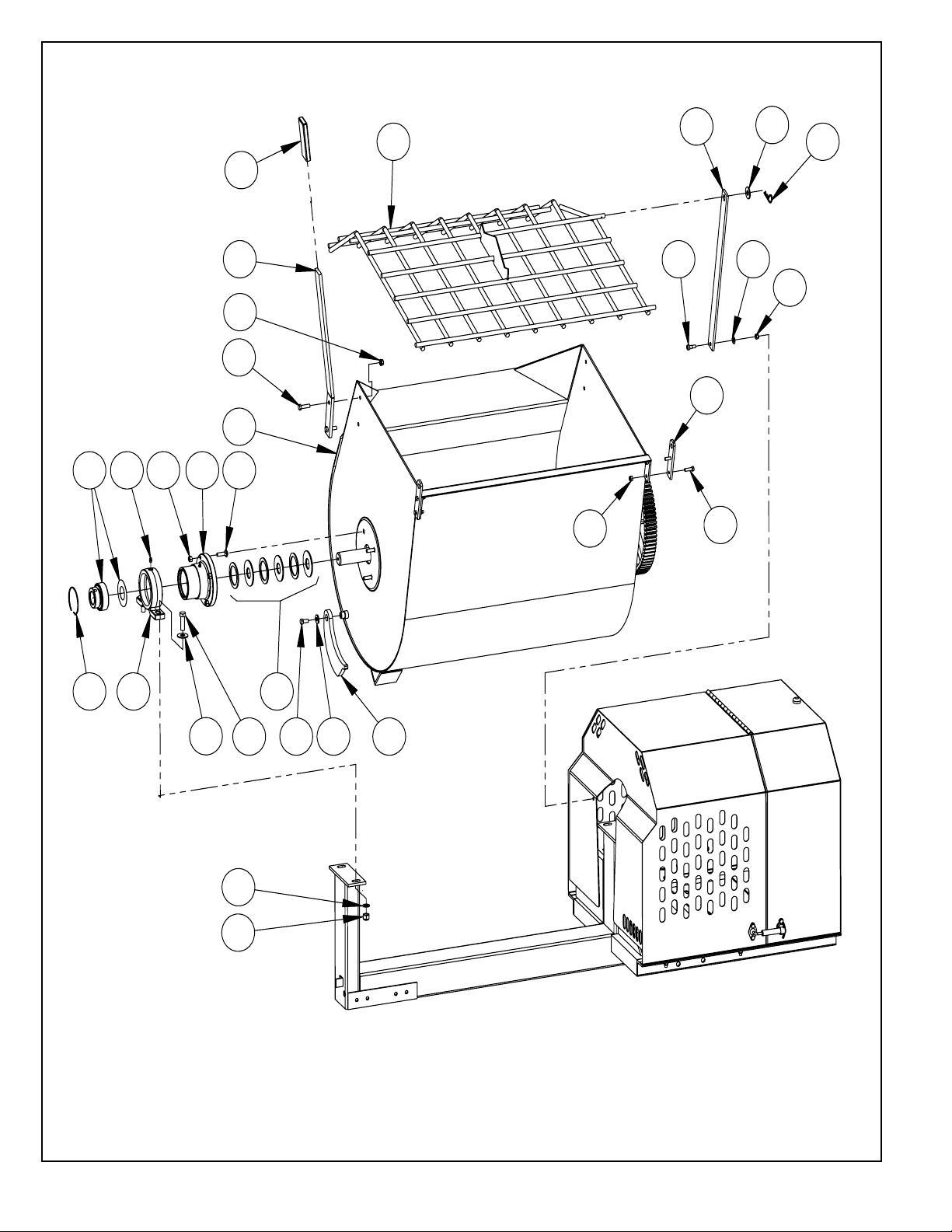
Drum Assembly
- 14 -
Page 18

ITEM PART NO. DESCRIPTION
MM60
MM80
1. 01056 HAIRPIN, 1/8” x 2-3/8” LONG 1 1 1
2. 01177 GREASE FITTING, 45 4 4 4
3. 01280 SOCKET HEAD SHOULDER SCREW, 3/8” x 3/8” 1 1 1
4. 01550 BALL BEARING (Includes seal & locking collar) 2 2 2
5. 05002 PILLOW BLOCK 2 2 2
6. 05082 BRACKET, GRID SUPPORT 2 2 2
7. 05475 RING, RETAINING 2 2 2
8. 05665 TRUNNION 2 2 2
9. 05918 SEAL KIT 2 2 2
10. 06327 WASHER 4 4 4
11. 16737 HANDLE, DUMP 1 1 1
12. 16806 GRID, MM60 1
16807 GRID, MM80 1
16781 GRID, MM90 1
13. 16832 OPENER, GRID, MM60 1
16782 OPENER, GRID 1 1
14. 17076 DRUM, MM60 1
17077 DRUM, MM80 1
17078 DRUM, MM90 1
15. 17079 LOCKING BAR 1 1 1
16. 18903 GRIP, DUMP HANDLE 1 1 1
17. F051808HCS HEX HEAD CAP SCREW, 5/16-18 x 1” 4 4 4
18. F0518ELN ELASTIC LOCKNUT, 5/16-18 5 5 5
19. F061606HCS HEX HEAD CAP SCREW, 3/8-16 x 3/4” 1 1 1
20. F061610CB CARRIAGE BOLT, 3/8-16 x 1-1/4” 8 8 8
21. F061610HCS HEX HEAD CAP SCREW, 3/8-16 x 1-1/4” 2 2 2
22. F0616ELN ELASTIC LOCKNUT, 3/8-16 2 2 2
23. F0616HN HEX NUT, 3/8-16 8 8 8
24. F06PW WASHER, 3/8” SAE 1 1 1
25. F06SW WASHER, 3/8” 1 1 1
26. F081314HCS HEX HEAD CAP SCREW, 1/2-13 x 1-3/4” 4 4 4
27. F0813ELN LOCKNUT, 1/2-13 NYLOC ZP 4 4 4
28. F08SW WASHER, 1/2” 5 5 5
MM90
REPLACEMENT KITS
01427 GREASE FITTING CAPS (Set of 12) 1 1 1
06090 TRUNNION ASSEMBLY (Includes 2,4,7-9) 2 2 2
17230* DRUM ASSEMBLY, MM60 1
17231* DRUM ASSEMBLY, MM80 1
17232* DRUM ASSEMBLY, MM90 1
* Includes trunnions, pillow blocks, shaft, paddles, & grid
- 15 -
Page 19
5.5 HP HONDA
36
35
39
38
37
34
31
33
32
1
25
5
2
2
3
20
13
14
21
24
22
9
15
12
11
19
18
30
29
28
23
4
6
26
17
6
8
10
16
729
30
28
27
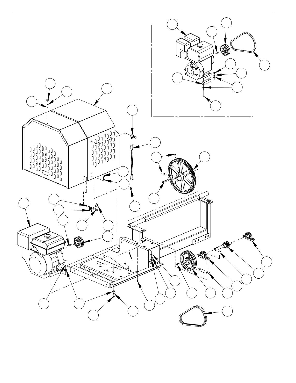
Drivetrain Assembly
- 16 -
Page 20

ITEM PART NO. DESCRIPTION
MM60
MM80
1. 01159 KEY, 3/8” SQUARE x 3” LONG 1 1 1
2. 01160 KEY, 1/4” SQUARE x 2” LONG 2 2 2
3. 01561 SHEAVE, 2A - 4” (8 hp Honda) 1 1 1
4. 01562 SHEAVE, 2A - 8” 1 1 1
5. 01563 SPUR GEAR, 84 TOOTH 1 1 1
6. 05586 BEARING, PILLOW BLOCK 2 2 2
7. 05692 SHIM, MIXER (AS REQUIRED) 111
8. 05741 V-BELT, AX-38 2 2 2
9. 07592 TERMINAL, SPLICE 1 1 1
10. 07755 ENGINE, HONDA 8 HP 1 1 1
11. 16750 BUMPER, RUBBER 1 1 1
12. 16783 SWITCH 1 1 1
13. 16813 LATCH, METAL 2 2 2
14. 16816 CATCH PLATE, METAL LATCH 2 2 2
15. 16820 HARNESS, WIRING 1 1 1
16. 17135 SHROUD ASSEMBLY (Includes 11,13,14 & 18-21) 1 1 1
17. 17404 PINION GEAR SHAFT, 12 TOOTH 1 1 1
18. F0324HN HEX NUT, #10-24 1 1 1
19. F03LW LOCKWASHER, #10 1 1 1
20. F042004HCS HEX HEAD CAP SCREW, 1/4-20 x 1/2” 8 8 8
21. F0420FN FLANGE NUT, 1/4-20 8 8 8
22. F051808HCS HEX HEAD CAP SCREW, 5/16-18 x 1” 4 4 4
23. F0518ELN ELASTIC LOCKNUT, 5/16-18 4 4 4
24. F05SW WASHER, 5/16” 4 4 4
25. F061610SHS SQUARE HEAD SET SCREW, 3/8-16 x 1-1/4” 2 2 2
26. F061612CB CARRIAGE BOLT, 3/8-16 x 1-1/2” 4 4 4
27. F061616HCS HEX HEAD CAP SCREW, 3/8-16 x 2” 4 4 4
28. F0616HN HEX NUT, 3/8-16 8 8 8
29. F06LW LOCKWASHER, 3/8” 8 8 8
30. F06SW WASHER, 3/8” 12 12 12
5.5 HP HONDA ENGINE OPTION
31. 00032 KEY, 3/16” SQUARE x 1-5/8” LONG 1
32. 05606 V-BELT, COGGED (AX-37) - S/N 7010432 and above 2
05741 V-BELT, COGGED (AX-38) - S/N 7010431 and below 2
33. 15223 SHEAVE, 2A - 4” 1
34. 15224 ENGINE, HONDA 5.5 HP 1
35. 17703 SPACER, 5.5 HP ENGINE - S/N 7010432 and above 2
36. F051822HCS HEX HEAD CAP SCREW, 5/16-18 x 2-3/4” 4
37. F0518HN HEX NUT, 5/16-18 4
38. F05LW LOCKWASHER, 5/16” 4
39. F05SW WASHER, 5/16” 8
MM90
SERVICE PARTS
06028 SHAFT ASSEMBLY, INTERMEDIATE (Includes 6 & 17)
- 17 -
Page 21
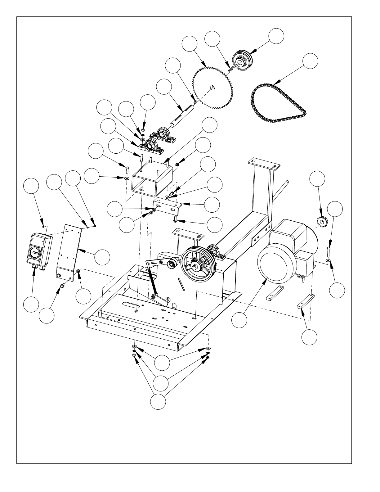
Electric Motor Drivetrain Assembly
- 18 -
Page 22

ITEM PART NO. DESCRIPTION
1. 01160 KEY, 1/4” SQUARE x 2” LONG 2 2
2. 01283 KEY, 1/4” SQUARE x 1-1/4” LONG 1 1 1
3. 01561 SHEAVE, 2A - 4” 1 1 1
4. 19876 SHAFT, INTERMEDIATE 1 1 1
5. 05586 BEARING, PILLOW BLOCK 2 2 2
6. 16585 SPROCKET, 60 TOOTH 1 1 1
7. 06067 MOTOR, ELECTRIC 1.5 HP, 1-PHASE, 230 VOLT 1
19918 MOTOR, ELECTRIC 1.5 HP, 1-PHASE, 115 VOLT
06025 MOTOR, ELECTRIC 2 HP, 1-PHASE, 230 VOLT 1
16729 MOTOR, ELECTRIC 3 HP, 1-PHASE, 230 VOLT 1
8. 16936 STAND, PILLOW BLOCK 1 1 1
9. 16939 CHAIN, #40 ROLLER, 35” 1 1 1
10. 16940 BRACKET, MOUNTING 1
11. 16941 ANGLE 1 1 1
12. 16942 SPROCKET, 14 TOOTH 1 1 1
13. 16943 BAR 2 2 2
14. F023206PMS PAN HEAD MACHINE SCREW, #8-32 x 3/4” 2 2 2
15. F0232HN HEX NUT, #8-32 4
16. F02LW LOCK WASHER, #10 4
17. F061608FWS FLANGE LOCKING SCREW, 3/8-16 x 1” 2 2 4
18. F061608HCS HEX HEAD CAP SCREW, 3/8-16 x 1” 2 2 2
19. F061610HCS HEX HEAD CAP SCREW, 3/8-16 x 1-1/4” 1 1 1
20. F061612HCS HEX HEAD CAP SCREW, 3/8-16 x 1-1/2” 4 4 4
21. F061616HCS HEX HEAD CAP SCREW, 3/8-16 x 2” 4 4 4
22. F0616FN FLANGE LOCK NUT, 3/8-16 2 2 4
23. F0616HN HEX NUT, 3/8-16 11 11 11
24. F06LW LOCK WASHER, 3/8” 11 11 11
25. F06SW WASHER, 3/8” 16 16 16
2HP
1.5HP
3 HP
2
REPLACEMENT KITS
06068 ADAPTER, 145T TO 182-184T FRAME (Included with 1.5hp motor)
19916 MOTOR CONTROLLER, 115V 20 AMP (ENCLOSURE & STARTER)
19917
19919 SWITCH ENCLOSURE
19920 MOTOR STARTER, 115V 20 AMP
19921 MOTOR STARTER, 230V 16 AMP
MOTOR CONTROLLER, 230V 16 AMP (ENCLOSURE & STARTER)
- 19 -
Page 23
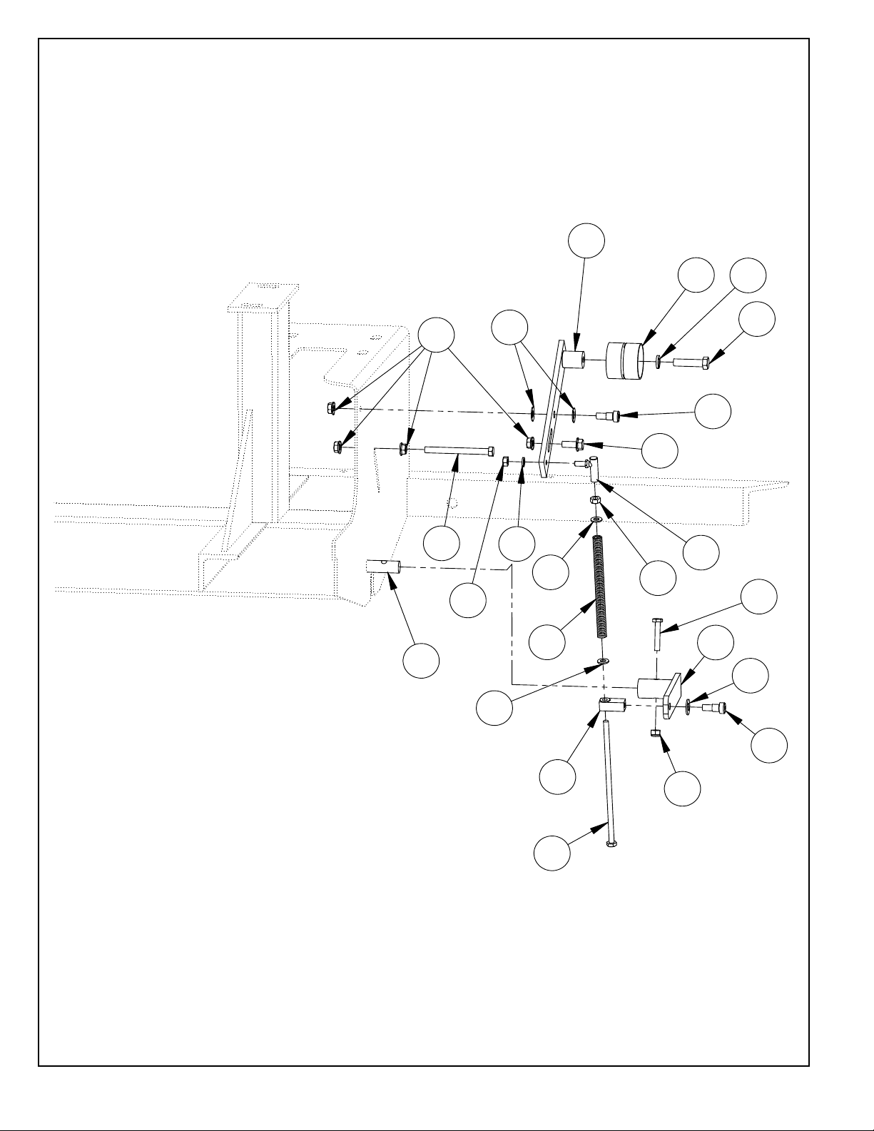
13
1
21
9
15
4
10
6
20
19
17
1
12
16
2
14
7
5
11
13
15
3
18
8
Idler Assembly
- 20 -
Page 24

ITEM PART NO. DESCRIPTION
MM60
MM80
1. 01280 SOCKET HEAD SHOULDER SCREW, 3/8” x 3/8” 2 2 2
2. 12422 SPRING WASHER, 3/8” x 3/4” 2 2 2
3. 16733 ACTUATOR 1 1 1
4. 16736 ARM, IDLER 1 1 1
5. 16887 SWIVEL ASSEMBLY 1 1 1
6. 16784 PULLEY, FLAT IDLER 1 1 1
7. 16786 JOINT, BALL 1 1 1
8. 16828 ENGAGEMENT HANDLE, MM60 1
16829 ENGAGEMENT HANDLE, MM80 1
16752 ENGAGEMENT HANDLE, MM90 1
9. 16933 SPRING, COMPRESSION 1 1 1
10. F042012HCS HEX HEAD CAP SCREW, 1/4-20 x 1-1/2” 1 1 1
11. F0420ELN ELASTIC LOCKNUT, 1/4-20 1 1 1
12. F042856HCS HEX HEAD CAP SCREW, 1/4-28 x 7” 1 1 1
13. F0428HN HEX NUT, 1/4-28 2 2 2
14. F04LW LOCKWASHER, 1/4” 1 1 1
15. F04SW WASHER, 1/4” 2 2 2
16. F051806FWS FLANGE BOLT, 5/16-18 x 3/4” 1 1 1
17. F051826HCS HEX HEAD CAP SCREW, 5/16-18 x 3-1/4” 1 1 1
18. F0518FN FLANGE NUT, 5/16-18 4 4 4
19. F061612HCS HEX HEAD CAP SCREW, 3/8-16 x 1-1/2” 1 1 1
20. F06LW LOCKWASHER, 3/8” 1 1 1
21. F06PW WASHER, 3/8” SAE 1 1 1
MM90
REPLACEMENT KITS
17609 ROD ASSEMBLY (INCLUDES 1, 5, 7, 9, 10, 13, 14, 16, 22)
- 21 -
Page 25
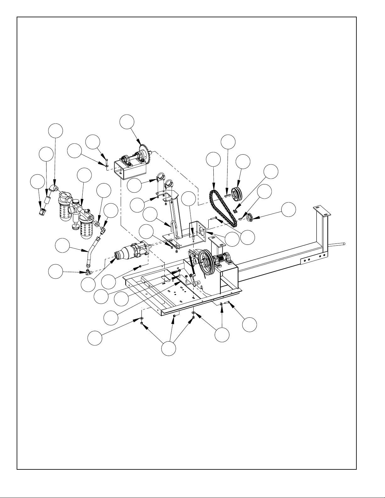
18
23
26
12
21
6
1
5
16
2
4
20
17
23
14
24
8
3
7
9
10
11
19
11
13
21
25
22
15
26
24
26
23
Air Mixer Assembly
- 22 -
Page 26

ITEM PART NO. DESCRIPTION QTY
1. 01160 KEY, 1/4 SQ X 2 1
2. 01204 CHAIN, CONNECTING LINK #50 1
3. 01239 NIPPLE 1
4. 01283 KEY, 1/4 SQ X 1-1/4 RD ENDS 1
5. 01561 SHEAVE, TWO GROOVE 2AK44 X 1 1
6. 06065 CHAIN, ROLLER #50 X 35-1/2 1
7. 06116 FITTING, PIPE REDUCER 1 X 3/4 1
8. 08280 FITTING, PIPE 90 DEG STREET X 1 1
9. 08910 REGULATOR UNIT, COMBINATION 1
10. 11379 REDUCER 1
11. 12199 FITTING, ELBOW PARKER 10-CTX-S 2
12. 14731 CLAMP, MUFFLER (1-5/8) 2
13. 15081 AIR MOTOR 1
14. 15085 2-1/2 MUFFLER CLAMP 1
15. 16941 ANGLE 1
16. 18029 SPROCKET, H5012, 1” BORE 1
17. 18039 SUPPORT, AIR MOTOR, MIXER 1
18. 18045 JACKSHAFT, AIR MIXER 1
19. 18046 HOSE, HYDRAULIC, 5/8 X 12 LP 1
20. F051814FWS FWLS, 5/16-18 X 1-3/4 GR5 ZP 4
21. F0518ELN LOCKNUT, 5/16-18 NYLOC ZP 8
22. F061608FWS FWLS, 3/8-16 X 1 ZP 2
23. F061610HCS HHCS, 3/8-16 X 1-1/4 GR5 ZP 7
24. F0616ELN LOCKNUT, 3/8-16 NYLOC ZP 9
25. F0616FN FLANGE WHIZ-LOCK NUT, 3/8-16 2
26. F06SW WASHER, 25/64 X 1 X 1/8 ZP 8
- 23 -
Page 27
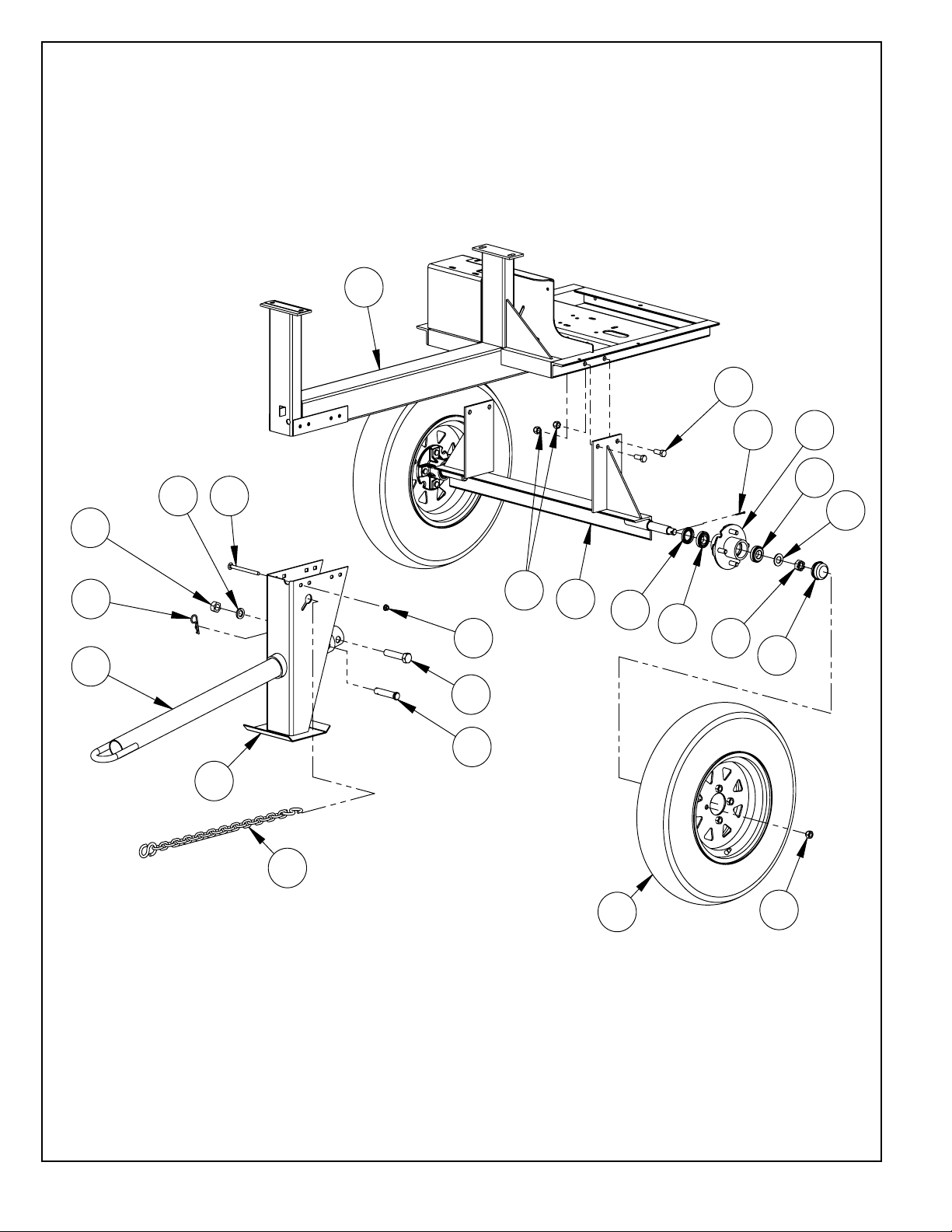
Frame & Axle Assembly
- 24 -
Page 28
ITEM PART NO. DESCRIPTION
MM60
MM80
1. 01158 PIN, HITCH 1 1 1
2. 01170 SEAL, GREASE 2 2 2
3. 01171 BEARING, 1” (Cup & cone) 4 4 4
4. 01174 CASTLE NUT, 3/4-16 2 2 2
5. 01175 COVER, DUST 2 2 2
6. 01235 WASHER 2 2 2
7. 01557 WHEEL, 4.80” x 12” 2
06442 WHEEL, ST175/80D13 2 2
8. 01558 HUB ASSEMBLY 4-BOLT, 1” (Includes 2-6, 9,16) 2 2 2
9. 05844 WHEEL NUT, 1/2-20 8 8 8
10. 16564 TOW POLE, BALL HITCH (Includes 22-24) 1 1 1
16773 TOW POLE, PINTLE HITCH (Includes 22-24) 1 1 1
11. 16743 LEG, FRONT 1 1 1
12. 16771 CHAIN, SAFETY (10 ft.) 1 1 1
13. 16817 AXLE, 12” WHEELS (Includes hubs) 1
16818 AXLE, 13” WHEELS (Includes hubs) 1 1
14. 17073 FRAME, MM60 1
17074 FRAME, MM80 1
17075 FRAME, MM90 1
15. 17158 HAIRPIN, 5/32” x 2-11/16” LONG 1 1 1
16. F0210CP COTTER PIN, 1/8” x 1-1/4” 2 2 2
17. F061640CB CARRIAGE BOLT, 3/8-16 x 5” 4 4 4
18. F0616FN FLANGE NUT, 3/8-16 4 4 4
19. F081310HCS HEX HEAD CAP SCREW, 1/2-13 x 1-1/4” 4 4 4
20. F0813ELN HEX NYLOC NUT, 1/2-13 4 4 4
21. F121628HCS HEX HEAD CAP SCREW, 3/4-16 x 3-1/2” 1 1 1
22. F12LW LOCKWASHER, 3/4” 1 1 1
23. F1216HN HEX NUT, 3/4-16 1 1 1
MM90
REPLACEMENT KITS
07334 WHEEL STUD (Round serrated shank - Cast iron hub) 8 8 8
ACCESSORIES
17957 3” MIXER LIFT KIT
19866 KIT, TORSION AXLE
- 25 -
Page 29
1
10
13
5
16
8
15
17
16
11
15
13
15
7
6
12
2
317
14
9
13
15
4
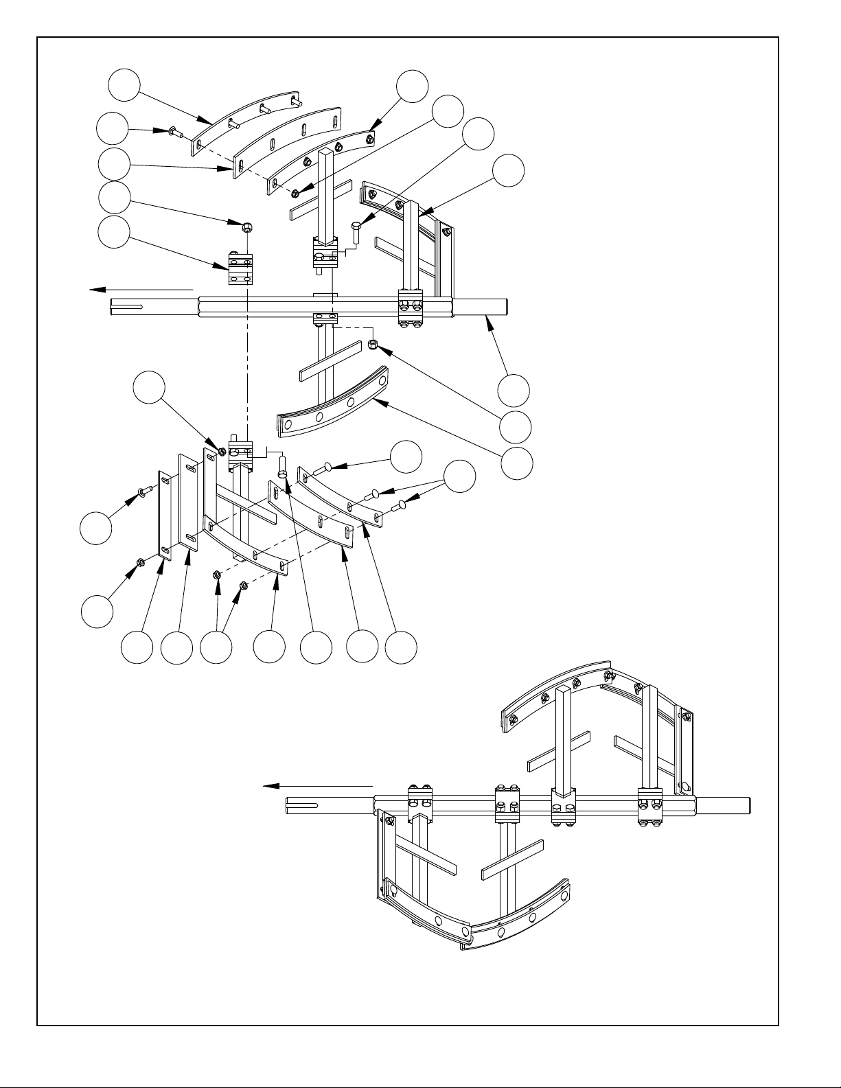
MM90 PADDLE ORIENTATION
TO ENGINE
TO ENGINE
Paddle Assembly
- 26 -
Page 30
ITEM PART NO. DESCRIPTION
MM60
MM80
1. 05821 MAIN SHAFT, MM60 1
05006 MAIN SHAFT, MM80 1
05648 MAIN SHAFT, MM90 1
2. 17574 RUBBER BLADE, END* 2 2 2
3. 18540 STEEL BLADE, END 2 2 2
4. 17576 RUBBER BLADE, CENTER* 2 2 2
5. 18543 STEEL BLADE, CENTER 2 2 2
6. 17578 RUBBER BLADE, WIPER* 2 2 2
7. 18544 STEEL BLADE, WIPER 2 2 2
8. 17585 PADDLE CLAMP 2 2 4
9. 17620 PADDLE ASM, END RIGHT (Includes 2,3,6,7, 13-17) 1
17570 PADDLE ASM, END RIGHT (Includes 2,3,6,7, 13-17) 1 1
10.
11. 17622 PADDLE ASM, CENTER LEFT (Includes 4-5, 13-17) 1
12. 17623 PADDLE ASM, END LEFT (Includes 2-3,6,7, 13-17) 1
13. F061610CB CARRIAGE BOLT, 3/8-16 x 1-1/4” 14 14 14
14. F061614CB CARRIAGE BOLT, 3/8-16 x 1-3/4” 2 2 2
15. F0616FN FLANGE LOCK NUT, 3/8-16 16 16 16
16. F0813ELN ELASTIC LOCKNUT, 1/2-13 12 12 16
17. F081313HCS HEX HEAD CAP SCREW, 1/2-13 x 1-5/8” 12 12 16
17621 PADDLE ASM, CENTER RIGHT (Includes 4,5, 13-17) 1
17571 PADDLE ASM, CENTER RIGHT (Includes 4-5, 13-17) 1 1
17572 PADDLE ASM, CENTER LEFT (Includes 4,5, 13-17) 1 1
17573 PADDLE ASM, END LEFT (Includes 2,3,6,7, 13-17) 1 1
MM90
REPLACEMENT KITS
*17597 RUBBER BLADE KIT (Includes 2, 4, 6) 1 1 1
*19613 KIT, MIXER SCRAPER HARDWARE (Includes 13, 14, 15)
- 27 -
Page 31

WARRANTY
WHAT DOES THIS WARRANTY COVER? MBW, Incorporated (MBW)
warrants each New Machine against defects in material and workmanship
for a period of twelve (12) months. "New Machine" means a machine
shipped directly from MBW or authorized MBW dealer to the end user. This
warranty commences on the first day the machine is sold, assigned to a
rental fleet, or otherwise put to first use.
MBW warrants each Demonstration Machine against defects in material
and workmanship for a period of six (6) months. "Demonstration Machine"
means a machine used by MBW or its agents for promotional purposes.
This warranty commences on the first day the machine is sold, assigned to
a rental fleet, or otherwise put to first use.
This warranty covers the labor cost for replacement or repair of parts,
components, or equipment on New Machines or Demonstration Machines,
and MBW shall pay labor costs at MBW's prevailing rate to affect the
warranted repair or replacement. MBW reserves the right to adjust labor
claims on a claim-by-claim basis.
This warranty covers the shipping cost of replacement parts, components,
or equipment via common ground carriers from MBW to an authorized
MBW dealer. Air freight is considered only in cases where ground
transportation is not practical.
MAY THIS WARRANTY BE TRANSFERRED? This warranty is nontransferable and only applies to the original end user of a new machine or
demonstration machine.
WHAT DOES THIS WARRANTY NOT COVER?
1.This warranty does not cover any Used Equipment. "Used Equipment"
means any MBW machine or equipment that is not a New Machine or a
Demonstration Machine. All Used Equipment is sold AS IS/WHERE IS
WITH ALL FAULTS.
2.This warranty does not cover any New Machine, Demonstration
Machine, or their equipment, parts, or components altered or modified in
any way without MBW's prior written consent. This warranty does not
cover the use of parts not specifically approved by MBW for use on MBW
products. This warranty does not cover misuse, neglect, shipping damage,
accidents, acts of God, the operation of any New Machine or
Demonstration Machine in any way other than recommended by MBW in
accordance with its specifications, or any other circumstances beyond
MBW's control. This warranty does not cover any New Machine or
Demonstration Machine repaired by anyone other than MBW factory
branches or authorized MBW distributors.
3.This warranty does not cover, and MBW affirmatively disclaims, liability
for any damage or injury resulting directly or indirectly from design,
materials, or operation of a New Machine or Demonstration Machine or any
other MBW product. MBW's liability with respect to any breach of warranty
shall be limited to the provisions of this document and in no event shall
exceed an amount equal to the purchase price of the New Machine or
Demonstration Machine purchased from MBW.
6.This warranty does not cover any updates to any New Machine,
Demonstration Machine, or any other MBW product. MBW reserves the
right to improve or make product changes without incurring any obligation
to update, refit, or install the same on New Machines or Demonstration
Machines previously sold.
WHAT MUST YOU DO TO OBTAIN WARRANTY COVERAGE? Each
New Machine or Demonstration Machine is accompanied by a Warranty
Registration Card. You must sign, date, and return the Warranty
Registration Card to the place of origin of the New Machine or
Demonstration Machine, either to MBW, Inc. at P.O. Box 440, Slinger,
Wisconsin 53086, MBW (UK), Ltd. at Units 2 & 3 Cochrane Street, Bolton
BL3 6BN, United Kingdom or MBW FRANCE SARL at
ZA D'Outreville, 5 Rue Jean Baptiste Neron, Bornel 60540 France, within
ten (10) days after purchase, assignment to a rental fleet, or first use. This
signed warranty card is the buyer's affirmation that he has read,
understood, and accepted the warranty at the time of purchase. Failure to
return the warranty card as specified herein renders the warranty null and
void. In order to receive warranty coverage consideration, warranty claims
must be submitted within thirty (30) days after the New Machine or
Demonstration Machine fails. Warranty claims must be submitted to MBW,
Inc., MBW (UK), Ltd. or MBW FRANCE SARL, and written authorization for
the return of merchandise or parts under the warranty must be obtained
before shipment to MBW.
WHAT WILL MBW DO? MBW's obligation under this warranty is limited to
the replacement or repair of parts for a New Machine or Demonstration
Machine at MBW factory branches or at authorized MBW distributors, and
such replacement or repair is the exclusive remedy provided hereunder.
Labor must be performed at an authorized MBW distributor. MBW
reserves the right to inspect and render a final decision on each warranty
case, and MBW's repair or replacement is solely within the discretion of
MBW.
S
EXPRESSLY AGREED THAT THIS SHALL BE THE SOLE AND
IT I
EXCLUSIVE REMEDY UNDER THIS WARRANTY. UNDER NO
CIRCUMSTANCES SHALL MBW BE LIABLE FOR ANY COSTS, LOSS,
EXPENSE, DAMAGES, SPECIAL DAMAGES, INCIDENTAL DAMAGES,
OR PUNITIVE DAMAGES ARISING DIRECTLY OR INDIRECTLY FROM
THE USE OF THE NEW MACHINE OR DEMONSTRATION MACHINE
WHETHER BASED UPON WARRANTY, CONTRACT, NEGLIGENCE,
STRICT LIABILITY, OR ANY OTHER LEGAL THEORY.
THE FOREGOING WARRANTY IS EXPRESSLY IN LIEU OF ALL
OTHER WARRANTIES, EXPRESS OR IMPLIED, INCLUDING THE
WARRANTIES OF MERCHANTABILITY, FITNESS FOR USE, AND
FITNESS FOR A PARTICULAR PURPOSE, AND ALL OTHER
OBLIGATIONS OR LIABILITY ON MBW'S PART. MBW NEITHER
ASSUMES NOR AUTHORIZES ANY OTHER PERSON TO ASSUME ON
BEHALF OF MBW ANY OTHER LIABILITY OR WARRANTY IN
CONNECTION WITH THE SALE OR SERVICE OF ANY NEW MACHINE,
DEMONSTRATION MACHINE , OR ANY OTHER MBW PRODUCT.
4.This warranty does not cover engines, motors, and other assemblies or
components produced by other manufacturers and used on a New
Machine or Demonstration Machine, as said engines, motors, and other
assemblies or components may have warranties provided by the
manufacturer thereof. This warranty does not apply to consumable items,
such as v-belts, filters, trowel and screed blades, seals, shock mounts,
batteries, and the like, all of which are sold AS IS/WHERE IS WITH ALL
FAULTS .
5.This warranty does not cover the cost of transportation and other
expenses which may be connected with warranty service but not
specifically mentioned herein.
EXTENDED RAMMER WARRANTY - MODELS R422, R442,
R482 & R483.
This extended warranty commences on the last day of MBW’s standard,
one year, “limited warranty” and runs for an additional four years
(48 months). This extended warranty is limited to part replacement and
shipping costs of rammer bellows and non-metallic slide bearings only.
This extended warranty does not cover labor, down time, or any other cost
beyond that of component replacement and freight. This extended
warranty is subject to all limitations set fourth in MBW’s “limited warranty”,
above.
- 28 -
Page 32

NOTES:
29
Page 33

NOTES:
30
 Loading...