

MBW vibratoy plates, gpr135, gpr99 User Manual
OPERATOR’S SAFETY
AND SERVICE MANUAL
GPR99 &
GPR135
This manual covers the following serial numbers
and higher for each model listed:
GPR99.......................................3090201
GPR135DE................................2900253
GPR135H...................................2910050
VIBRATOY PLATES
MBW, Inc.
250 Hartford Rd • PO Box 440
Slinger, WI 53086-0440
Phone: (262) 644-5234
Fax: (262) 644-5169
Email: mbw@mbw.com
Website: www.mbw.com
MBW (UK) Ltd.
Units 2 & 3 Cochrane Street
Bolton BL3 6BN, England
Phone: 01204 387784
Fax: 01204 387797
MBW FRANCE S.A.R.L.
Z.A. d’Outreville
11 rue Jean Baptiste Néron,
60540 BORNEL
FRANCE
Phone: +33 (0) 3 44 07 15 96
Fax: +33 (0) 3 44 07 41 28
Email: mbwfrance@free.fr
L17433 / 02.08.M
©MBW, Inc. 2004
Printed in the USA

TABLE OF CONTENTS
Safety Information . . . . . . . . . . . . . . . . . . . . . . 1
Introduction . . . . . . . . . . . . . . . . . . . . . . . . . . . . . . . . . 1
Safety Precautions . . . . . . . . . . . . . . . . . . . . . . . . . . . 1
Safety Decals . . . . . . . . . . . . . . . . . . . . . . . . . . . . . . . 1
Safety Decals: GPR135 (Decal Set #16031) . . . . . . . 2
Safety Decals: GPR99/135 (Decal Set #16031) . . . . 3
Specifications. . . . . . . . . . . . . . . . . . . . . . . . . . 4
Operation . . . . . . . . . . . . . . . . . . . . . . . . . . . . . 5
Introduction . . . . . . . . . . . . . . . . . . . . . . . . . . . . . . . . . 5
Before Operation . . . . . . . . . . . . . . . . . . . . . . . . . . . . 5
Engine. . . . . . . . . . . . . . . . . . . . . . . . . . . . . . . . . . . . . 5
Starting Gasoline Engine . . . . . . . . . . . . . . . . . . . . . . 5
Starting Diesel Engine . . . . . . . . . . . . . . . . . . . . . . . . 5
Running Engine . . . . . . . . . . . . . . . . . . . . . . . . . . . . . 5
Stopping Engine . . . . . . . . . . . . . . . . . . . . . . . . . . . . . 6
Lifting/Transporting . . . . . . . . . . . . . . . . . . . . . . . . . . . 6
Service. . . . . . . . . . . . . . . . . . . . . . . . . . . . . . . . 9
Torque Chart . . . . . . . . . . . . . . . . . . . . . . . . . . . . . . . 9
Service Tools . . . . . . . . . . . . . . . . . . . . . . . . . . . . . . . 9
Main Disassembly Procedure (Diesel Engine) . . . . . . 9
Main Disassembly Procedure (Gasoline Engine). . . 10
Exciter Oil Change Procedure . . . . . . . . . . . . . . . . . 10
Lower Hydraulic Seal Replacement . . . . . . . . . . . . . 11
Bleeding And Adjustment of Hydraulic Controls. . . . 11
Baseplate Disassembly Procedure . . . . . . . . . . . . . 12
Handle Disassembly Procedure . . . . . . . . . . . . . . . . 13
Control Head Disassembly Procedure . . . . . . . . . . . 13
Baseplate Assembly Procedure . . . . . . . . . . . . . . . . 14
Control Head Assembly Procedure . . . . . . . . . . . . . 17
Handle Assembly Procedure . . . . . . . . . . . . . . . . . . 17
Final Assembly . . . . . . . . . . . . . . . . . . . . . . . . . . . . . 17
Troubleshooting . . . . . . . . . . . . . . . . . . . . . . . . . . . . 18
Parts Replacement Cycles and Tolerances . . . . . . . 19
Maintenance . . . . . . . . . . . . . . . . . . . . . . . . . . . 7
Maintenance Schedule . . . . . . . . . . . . . . . . . . . . . . . . 7
Fluid Levels. . . . . . . . . . . . . . . . . . . . . . . . . . . . . . . . . 7
Engine Maintenance . . . . . . . . . . . . . . . . . . . . . . . . . . 7
Cleaning Plate . . . . . . . . . . . . . . . . . . . . . . . . . . . . . . 7
Engine Speed . . . . . . . . . . . . . . . . . . . . . . . . . . . . . . . 8
Battery Maintenance. . . . . . . . . . . . . . . . . . . . . . . . . . 8
Battery Charging. . . . . . . . . . . . . . . . . . . . . . . . . . . . . 8
Belt Adjustment. . . . . . . . . . . . . . . . . . . . . . . . . . . . . . 8
Replacement Parts . . . . . . . . . . . . . . . . . . . . . 20
MAIN ASSEMBLY . . . . . . . . . . . . . . . . . . . . . . . . . . 22
BASEPLATE ASSEMBLY . . . . . . . . . . . . . . . . . . . . 24
LOWER SHAFT ASSEMBLY . . . . . . . . . . . . . . . . . . 26
HANDLE ASSEMBLY . . . . . . . . . . . . . . . . . . . . . . . 28
GASOLINE ENGINE ASSEMBLY . . . . . . . . . . . . . . 30
DIESEL ENGINE ASSEMBLY . . . . . . . . . . . . . . . . . 32
Warranty . . . . . . . . . . . . . . . . . . . . . . . . . . . . . 34
WARNING
CALIFORNIA PROPOSITION 65 WARNING
Engine exhaust and some of its constituents are
known in the state of California to cause cancer,
birth defects, and other reproductive harm.
SAFETY INFORMATION
Introduction
This Safety Alert Symbol is used to call attention
to items or operations which may be dangerous
to those operating or working with this
equipment. The symbol can be found
throughout this manual and on the unit. Please read these
warnings and cautions, along with all decals, carefully
before attempting to operate the unit. Make sure every
individual who operates or works with this equipment is
familiar with all safety precautions.
WARNING
GENERAL WARNING. Indicates information
important to the proper operation of the
equipment. Failure to observe may result in
damage to the equipment and/or severe bodily
injury or death.
CAUTION
GENERAL CAUTION. Indicates information
important to the proper operation of the
equipment. Failure to observe may result in
damage to the equipment.
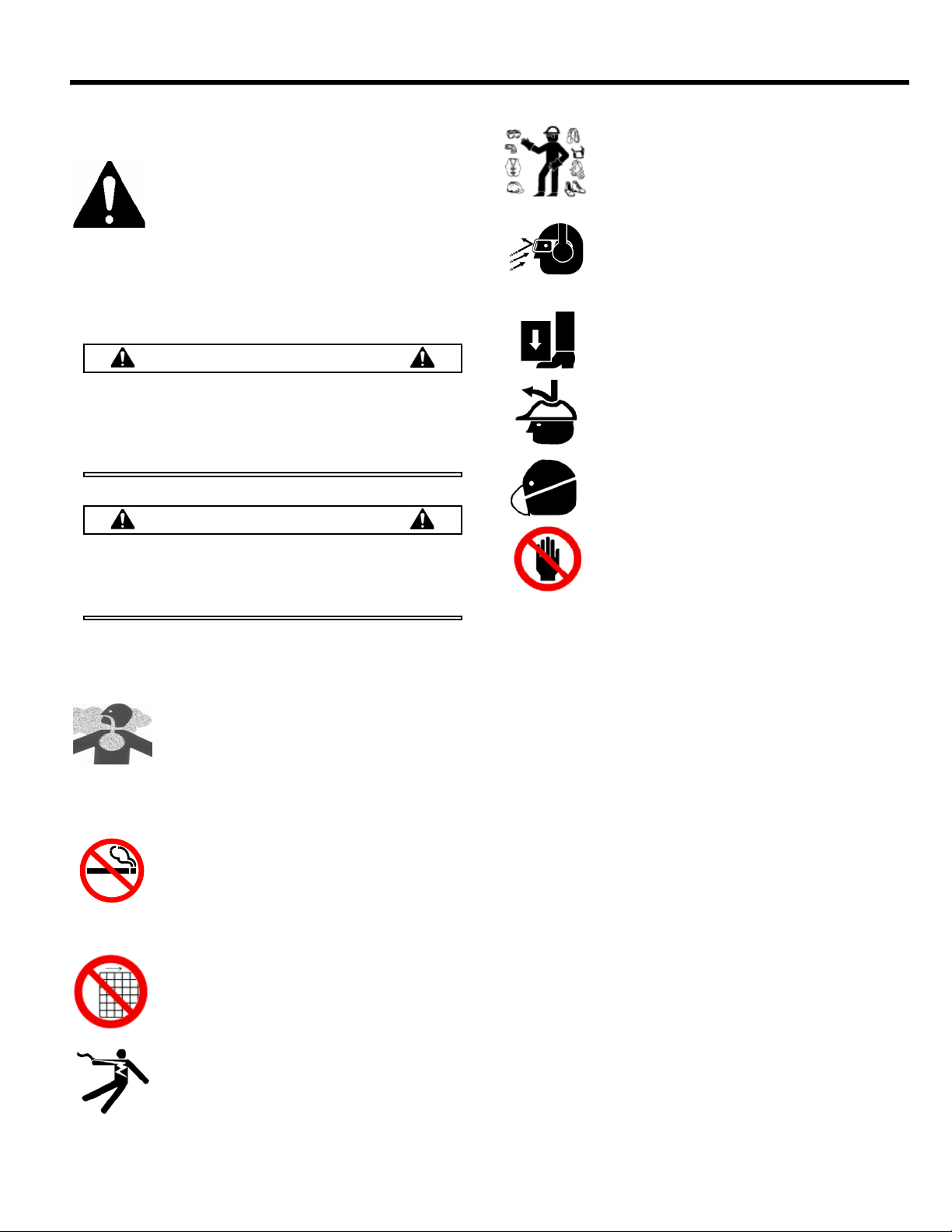
Safety Precautions
LETHAL EXHAUST GAS: An internal
combustion engine discharges carbon
monoxide, a poisonous, odorless, invisible
gas. Death or serious illness may result if
inhaled. Operate only in an area with proper
ventilation. NEVER OPERATE IN A
CONFINED AREA!
DANGEROUS FUELS: Use extreme caution
when storing, handling and using fuels, as
they are highly volatile and explosive in vapor
state. Do not add fuel while engine is running.
Stop and cool the engine before adding fuel.
DO NOT SMOKE!
SAFETY GUARDS: It is the owner's
responsibility to ensure that all guards and
shields are in place and in working order.
IGNITION SYSTEMS: Breakerless, magneto,
and battery ignition systems can cause severe
electrical shocks. Avoid contacting these
units or their wiring.
SAFE DRESS: Do not wear loose clothing,
rings, wristwatches, etc. near machinery.
NOISE PROTECTION: Wear OSHA specified
hearing protection devices.
EYE PROTECTION: Wear OSHA specified
eye shields, safety glasses, and sweat bands.
FOOT PROTECTION: Wear OSHA specified
steel-tipped safety shoes.
HEAD PROTECTION: Wear OSHA specified
safety helmets.
DUST PROTECTION: Wear OSHA specified
dust mask or respirator.
OPERATOR: Keep children and bystanders
off and away from the equipment.
REFERENCES: For details on safety rules and regulations
in the United States, contact your local Occupational Safety
and Health Administration (OSHA) office. Equipment
operated in other countries must be operated and serviced
in accordance and compliance with any and all safety
requirements of that country. The publication of these
safety precautions is done for your information. MBW does
not by the publication of these precautions, imply or in any
way represent that these are the sum of all dangers present
near MBW equipment. If you are operating MBW
equipment, it is your responsibility to insure that such
operation is in full accordance with all applicable safety
requirements and codes. All requirements of the United
States Federal Occupational Safety and Health
Administration Act must be met when operated in areas that
are under the jurisdiction of that United States Department.
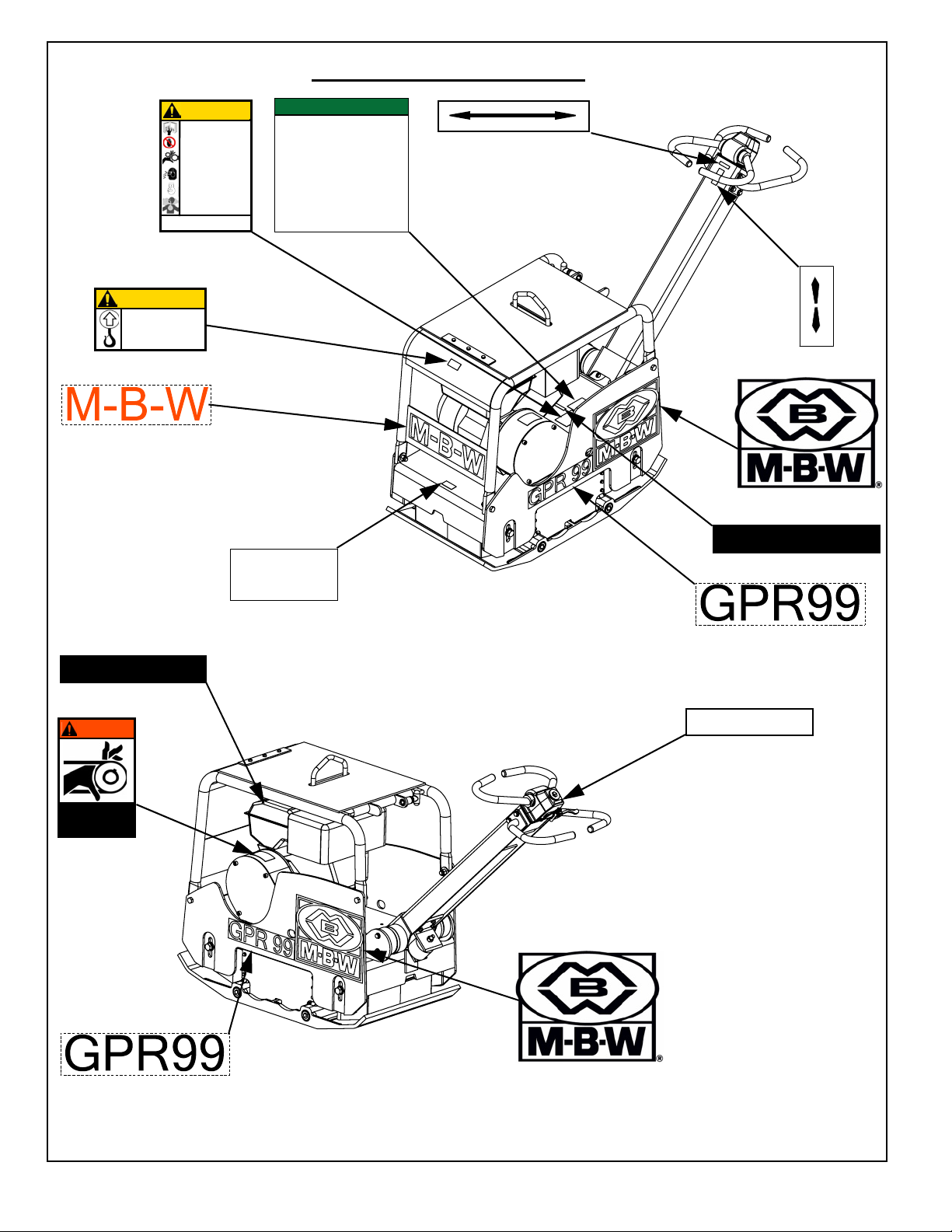
Safety Decals
Carefully read and follow all safety decals. Keep them in
good condition. If decals become damaged, replace as
required. If repainting the unit, replace all decals. Decals
are available from authorized MBW distributors. Order the
decal set listed on the following page(s).
- 1 -
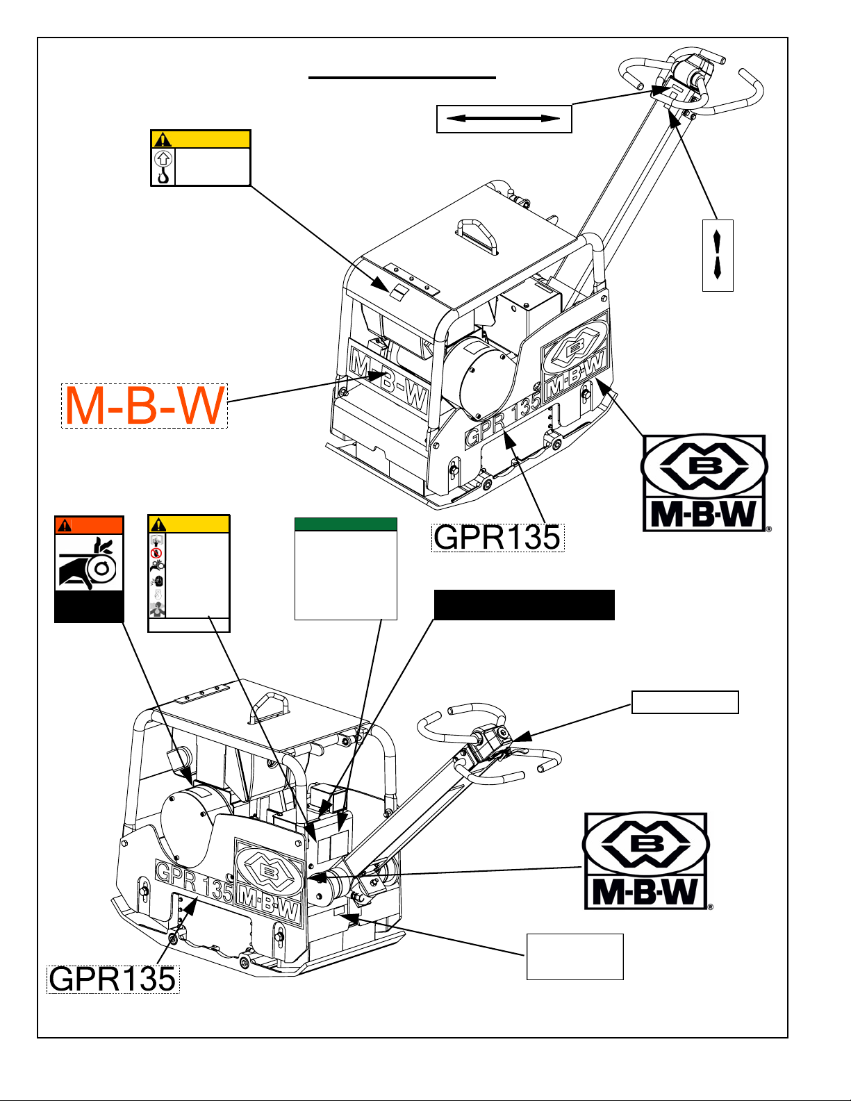
CAUTION
Machine may fall and cause
injury or damage if lifted
improperly.
15853
Lift only by lift hook
Weight~ #924 (420kg)
15855
#15847
#15853
DIESEL MODEL
IDLE STOP RUN
THROTTLE
19493
#19493
FORWARD
REVERSE
14665
#14665
WARNING
ROTATING PARTS
can crush and cut.
Keep hands away!
12573
#12573
CAUTION
Read the Operating Instructions
before operating this piece of
equipment.
Keep unauthorized and untrained
people away from this
equipment.
ROTATING & MOVING PARTS!
Make sure all guards and safety
devices are in place.
Wear approved hearing protection,
foot protection, eye protection and
head protection.
SHUT OFF the motor before servicing or cleaning.
STOP
DO NOT RUN in an enclosed area.
The engine produces carbon
monoxide, a POISONOUS GAS.
Failure to comply could result in serious
bodily injury.
#13483
DIESEL PLATE
OPERATING INSTRUCTIONS
1. Check engine oil level.
2. Check fuel level.
3. Set engine speed control in the middle position.
4. Move decompression lever (if equipped) to the up
position. (Located on top of the engine)
5. Use key (if equipped) or starting handle to start
engine (Refer to engine instruction book for proper
“Manual Starting” procedure.)
6. After starting return engine speed control to the idle
position and allow engine to reach operation
temperature.
7. During operation run engine at full throttle, when
excessive kickback is noticed maximum compaction
has been reached.
8. To stop, return throttle to the idle position and allow
engine to idle for one minute then move control to
stop position.
13483
#15832
15832
U.S. PATENT 7,165,469
19326 HYDRAULIC PLATE
#15855
#19326
HYDRAULIC OIL
#01554
15844
#15844
#01554
15855
#15855
Safety Decals: GPR135 (Decal Set #16031)
- 2 -
ENGINE
OIL DRAIN
#15845
15845
CAUTION
Machine may fall and cause
injury or damage if lifted
improperly.
16026
Lift only by lift hook
Weight~ #781(355kg)
HYDRAULIC OIL
15844
#15847
#16026
CAUTION
Read the Operating Instructions
before operating this piece of
equipment.
Keep unauthorized and untrained
people away from this
equipment.
ROTATING & MOVING PARTS!
Make sure all guards and safety
devices are in place.
Wear approved hearing protection,
foot protection, eye protection and
head protection.
SHUT OFF the motor before servicing or cleaning.
STOP
DO NOT RUN in an enclosed area.
The engine produces carbon
monoxide, a POISONOUS GAS.
Failure to comply could result in serious
bodily injury.
#13483
GASOLINE MODELS
DIESEL PLATE
OPERATING INSTRUCTIONS
1. Check engine oil level.
2. Check fuel level.
3. Set engine speed control in the middle position.
4. Move decompression lever (if equipped) to the up
position. (Located on top of the engine)
5. Use key (if equipped) or starting handle to start
engine (Refer to engine instruction book for proper
“Manual Starting” procedure.)
6. After starting return engine speed control to the idle
position and allow engine to reach operation
temperature.
7. During operation run engine at full throttle, when
excessive kickback is noticed maximum compaction
has been reached.
8. To stop, return throttle to the idle position and allow
engine to idle for one minute then move control to
stop position.
13483
#15866
IDLE RUN
THROTTLE
19492
#19492
15832
FORWARD
REVERSE
14665
#14665
#01554
UNLEADED GASOLINE
13481
#13481
WARNING
ROTATING PARTS
can crush and cut.
Keep hands away!
12573
#12573
ENGINE
OIL DRAIN
#15845
15845
U.S. PATENT 7,165,469
19326 HYDRAULIC PLATE
#19326
15856
GPR99 = #15856
GPR135 = #15855
#15844
GPR99 = #15856
GPR135 = #15855
Safety Decals: GPR99/135 (Decal Set #16031)
15856
#01554
- 3 -
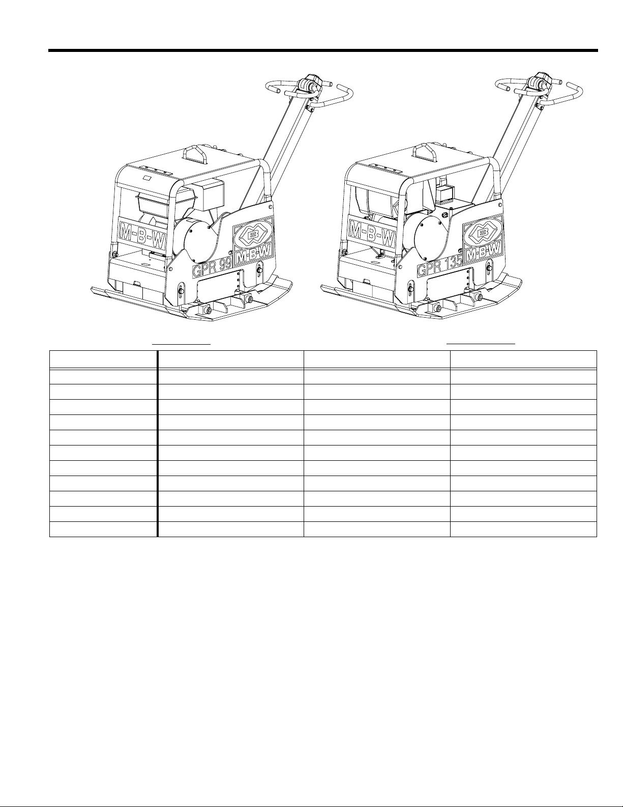
SPECIFICATIONS
*53
*53
GPR99H GPR135H GPR135DE
CENTRIFUGAL FORCE 9900lbf (44 kN) 13500 lbf (60kN) 13500 lbf (60kN)
EXCITER (VPM) 3840 vpm 3840 vpm 3840 vpm
TRAVEL SPEED 80 ft./min. (24 m/min.) 78 ft./min. (24 m/min.) 76 ft./min. (23 m/min.)
COMPACTION DEPTH 28 in (71 cm) 28 in (71 cm) 28 in (71 cm)
WIDTH x LENGTH 19.7 x 37.3 in. (50 x 95 cm) 19.7 x 37.3 in. (50 x 95 cm) 19.7 x 37.3 in. (50 x 95 cm)
OPERATING WEIGHT 775 lb. (352 kg) 825 lb. (374 kg) 882 lb. (400 kg)
ENGINE Honda GX390 20.6 in.³ (389 cm³) Honda GX390 20.6 in.³ (389 cm³) Hatz 1B40 28.2 in.³ (462 cm³)
FUEL Gas Gas Diesel
ENGINE SPEED 3600 rpm 3600 rpm 3600 rpm
STARTER SYSTEM Recoil Recoil Electric start with recoil
PLATE EXTENSIONS 3 in (7.6 cm) & 6 in. (15.2 cm) 3 in (7.6 cm) & 6 in. (15.2 cm) 3 in (7.6 cm) & 6 in. (15.2 cm)
Specifications subject to change without notice
- 4 -

OPERATION
Introduction
MBW Inc. equipment is intended for use in very severe
applications. They are powered by four cycle engines and
are available in different sizes and a selection of engines.
The MBW Reversible Plate Compactor is intended to
compact various soil types. Recommended soil types
include granular soils, gravel/sand mixtures, and semigranular cohesive soils.
The MBW Reversible Plate Compactor is not
recommended for use in cohesive soils nor for very hard
surfaces such as concrete or asphalt.
This parts manual contains only standard parts.
Variations of these parts as well as other special parts are
not included. Contact your local MBW Inc. Distributor for
assistance in identifying parts not included in this manual.
Before Operation
After receiving your new MBW Inc. Reversible Plate
Compactor, inspect it for any visible damage done during
shipment. Make sure the engine throttle works properly.
Contact your nearest MBW Inc. Distributor if there are any
problems.
Your new MBW Inc. Reversible Plate Compactor is
shipped complete and ready for use.
• REMEMBER It is the owner’s responsibility to
communicate information on the safe use and proper
operation of this unit to all operators.
• Review All of the Safety Precautions listed on page 1 of
this manual.
• Familiarize yourself with the operation of the equipment
and confirm that all controls function properly.
diesel fuel or unleaded gasoline dependent on engine
type. (See Engine “Owner’s Manual”)
• FUEL FILTER - If clogged or damaged, replace.
Engine
Refer to the engine manual for location of all controls and
features.
Starting Gasoline Engine
1. Open fuel valve.
2. Turn engine switch to on position.
3. Set throttle to idle position.
4. Choke engine if necessary, (you may not need to
choke a warm engine).
5. Pull starter rope repeatedly until engine starts.
6. Move choke to the off or open position.
7. Allow engine to warm up for one or two minutes.
Starting Diesel Engine
For detailed instructions refer to the engine Manual.
1. When starting the engine, the throttle lever on the
handle must be in the idle position.
2. The engine has an automatic decompression
system, however it is recommended to slowly pull the
starter rope until you feel a slight resistance. Let the
starter rope recoil completely and pull the starter rope
quickly, do not jerk the starter handle, until the engine
starts.
3. Let the engine warm up in the idle position for one or
two minutes.
• Know how to STOP the equipment in case of an
emergency.
• Make sure hands, feet, and clothing are at a safe
distance from any moving parts.
• OIL LEVEL - Check the oil level in the engine. For more
information see “Lubrication” under the respective
engine’s “Owner’s Manual” or the MAINTENANCE
section of this manual.
• AIR CLEANER - Check to ensure element is in good
condition and properly installed.
• FUEL SUPPLY - The engines on MBW Inc. Compaction
equipment require an automotive grade of clean, fresh,
Running Engine
1. After the engine warms up, fully open throttle.
2. The compactor will begin vibrating and moving in a
forward direction. Never leave compactor idling
unattended.
3. The MBW Reversible Plate Compactor is designed to
slowly move forward without application of the control
lever. The number of passes needed to reach the
compaction level desired will depend on soil type and
moisture. Maximum compaction of the soil has been
reached when excessive kickback is noticed in the
compactor.
- 5 -
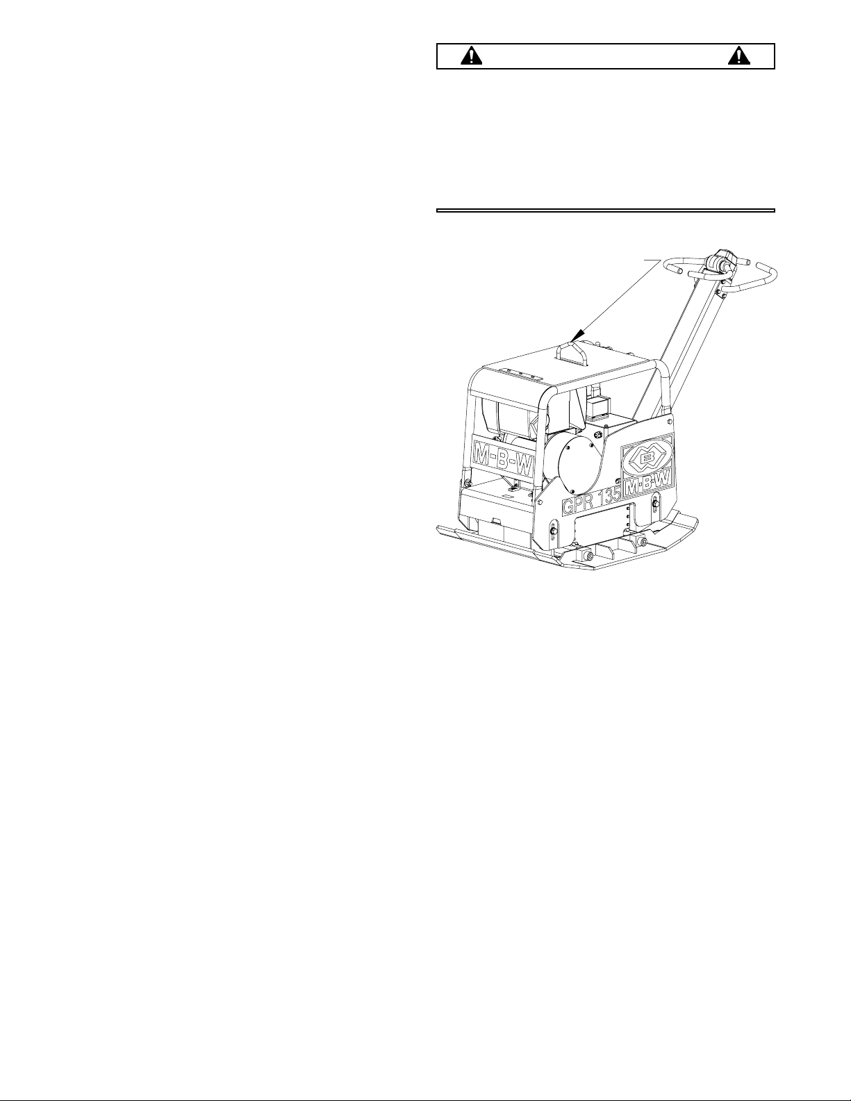
/,)76(&85(+(5(
Stopping Engine
WARNING
Always stop the engine before:
1. To stop the compactor from traveling forward, return
the engine throttle to idle position.
2. Whenever possible, it is recommended to let the
engine idle for one or two minutes before stopping.
3. Gas engines: Turn the switch on the engine to
“STOP” position.
Diesel engines: Move the throttle control to the
“STOP” position.
4. Turn off the fuel valve where applicable.
Lifting/Transporting
1. Lift unit by center lifting eye on rollcage.
2. The unit must be transported in the upright position.
DO NOT lay machine on its side.
3. Secure or tiedown unit using lift eye or roll cage when
transporting.
Adding fuel.
Leaving the equipment unattended, even if only
for a minute.
Before making any repairs or adjustments to the
machine.
- 6 -

MAINTENANCE
CAUTION
WARNING
Always exercise the stopping procedure before
servicing or lubricating the unit.
Always verify fluid levels and check for leaks after
changing fluids.
After servicing the unit, replace and fasten all
guards, shields, and covers to their original
positions before resuming operation.
Do not drain oil onto ground, into open streams,
or down sewage drains.
Maintenance Schedule
SYSTEM MAINTENANCE
Engine Refer to engine operator/owner manual X
Clean cooling fins XX
Belts Check for wear and retighten X
Exciter Check oil level X
Check for oil leaks X
Change oil XX
Tighten Bolts
Hydraulics Check level and refill X
Hardware
Shockmounts
Check and tighten as needed
Check for cracks or tears XX
1
1
EACH
USE
EVERY 50
HOURS
XX
XX
EVERY 100
HOURS
EVERY 250
HOURS
YEARLY
1. Check all hardware after the first 5 hours of use, then follow the maintenance schedule.
Fluid Levels
SYSTEM FLUID VOLUME RECOMMENDED OIL
Exciter
GPR99 32 oz. (0.95 Liter)
GPR135 32 oz. (0.95 Liter)
Hydraulic Oil
GPR99 8 oz. (.24 Liter) Chevron AW ISO32 or Rykon 32
GRP135 8 oz. (.24 Liter) Chevron AW ISO32 or Rykon 32
Engine Refer to engine operator/owner manual
1. MBW #01058 ---- 6-Pack (8 oz bottles)
MBW #17320---- 1 quart (32 oz)
Engine Maintenance
Refer to the engine owner’s manual for maintenance
intervals and procedures.
Cleaning Plate
Remove any excess debris which may get into the housing
of the unit.
MBW Ground Pounder
MBW Ground Pounder
®
Exciter Oil
®
Exciter Oil
1
1
- 7 -

Engine Speed
Battery Charging
1. Engine speed is factory set according to the speeds
listed in the Specifications section of this manual. Do
not tamper with the governor setting. The governor
establishes safe operating limits which must not be
exceeded.
2. Refer to the engine Owner’s Manual for procedure on
setting operating and idle speeds.
3. The engine operating speed should be set to 3600
RPM.
4. The engine idle speed must not exceed 1800 RPM. If
the idle speed is greater than 1800 RPM the clutch
may not disengage.
Battery Maintenance
1. The Odyssey battery is very different from standard
liquid-acid batteries that are openly vented.
2. The battery is, and operates as, a sealed battery,
recycling all gases internally. there is no corrosion to
the surrounding area.
3. The battery is shipped fully charged from the factory,
but prior to installation, check the battery’s voltage to
see if it is 12.65 volts or greater. If not, recharge it
using the procedure below. Caution: Never attempt
to remove the top decal cover, as it will cause the
battery to fail.
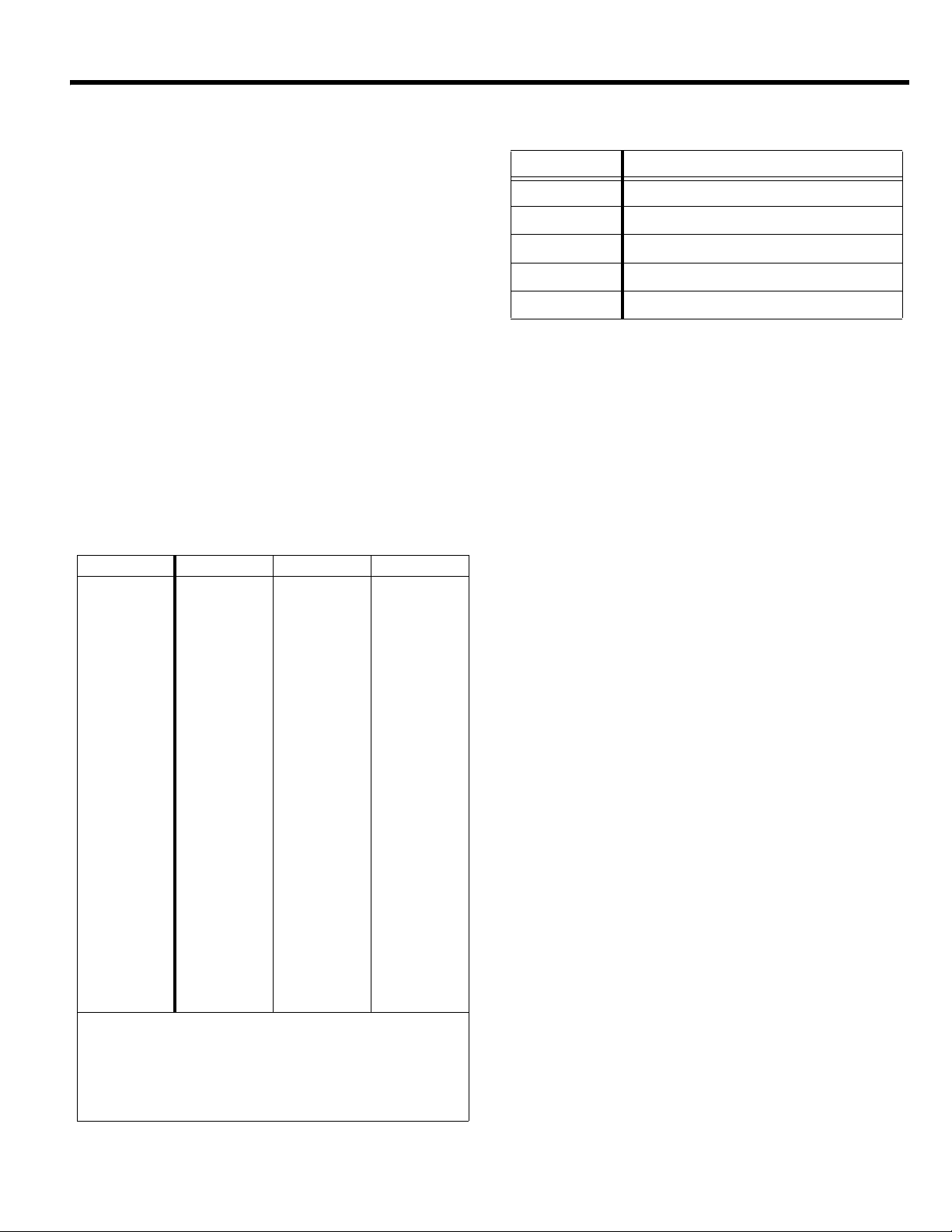
1. The state of charge in an Odyssey battery can be
determined from the following chart:
Voltmeter Reading State of Charge
12.84 Volts 100%
12.50 Volts 75%
12.18 Volts 50%
11.88 Volts 25%
2. To get a long life from the Odyssey battery, it is
important that the battery is kept near full charge,
approximately 12.8 volts.
3. If there are electrical loads during storage, then the
negative battery cable should be disconnected or a
Battery Tender trickle charge used. Low power 1.25
amp Battery Tenders will keep a fully charged battery
fully charged but cannot recharge if the battery
becomes discharged.
4. If a standard automotive charger is used to boost
charge a discharged battery it is important to make
sure the charging voltage does not exceed 15 volts
during charge. A hand held voltmeter can be used to
monitor this periodically. The following chart provides
recharge times under this type of boost charging to
an 80-95% recharge.
ODYSSEY Charge time for 100% discharged battery (11.5 volts)
Model 10-amp charger 20-amp charger
PC 925 2 1/2 hours 1 1/4 hours
Belt Adjustment
If any belt stretch develops follow these steps:
Refer to MAIN ASSEMBLY, page 22.
1. Remove the belt guard, refer to engine assembly
pages.
2. Loosen (do not remove) the four hex head
capscrews securing the engine deck to the
baseplate.
3. Tighten the belt by lifting the engine deck to provide
3/8 - 3/4 inch of “play” on one side of the belt. Be
sure to keep the engine deck level with the
baseplate when adjusting the belt.
4. Retighten the four hex head capscrews.
5. Reinstall the beltguard.
- 8 -
SERVICE
Assembly and disassembly should be preformed by a
service technician who has been factory trained on MBW
equipment. the unit should be clean and free of debris.
Pressure washing before disassembly is recommended.
• Prior to assembly, wash all parts in a suitable cleaner or
solvent.
• Check moving parts for wear and failure. Refer to the
Replacement Section of this manual for tolerances and
replacement cycles.
• All shafts and housings should be oiled prior to pressing
bearings. Also ensure that bearings are pressed square
and are seated properly.
• All bearings should be replaced when rebuilding any
exciter or gearbox.
• All gaskets and seals should be replaced after any
disassembly.
Torque Chart
SIZE GRADE 2 GRADE 5 GRADE 8
1/4-20 49 in
1/4-28 56 in
5/16-18 8 ft
5/16-24 9 ft
3/8-16 15 ft
3/8-24 17 ft
7/16-14 24 ft
7/16-20 27 ft
1/2-13 37 ft
1/2-20 41 ft
9/16-12 53 ft
5/8-11 73 ft
5/8-18 83 ft
3/4-16 144 ft
1-8 188 ft
1-14 210 ft
1-1/2-6 652 ft
M 6 3 ft
M 8 6 ft
M 10 10 ft
•lbs 76 in•lbs 9 ft•lbs
•lbs 87 in•lbs 10 ft•lbs
•lbs 13 ft•lbs 18 ft•lbs
•lbs 14 ft•lbs 20 ft•lbs
•lbs 23 ft•lbs 33 ft•lbs
•lbs 26 ft•lbs 37 ft•lbs
•lbs 37 ft•lbs 52 ft•lbs
•lbs 41 ft•lbs 58 ft•lbs
•lbs 57 ft•lbs 80 ft•lbs
•lbs 64 ft•lbs 90 ft•lbs
•lbs 82 ft•lbs 115 ft•lbs
•lbs 112 ft•lbs 159 ft•lbs
•lbs 112 ft•lbs 180 ft•lbs
•lbs 200 ft•lbs 315 ft•lbs
•lbs 483 ft•lbs 682 ft•lbs
•lbs 541 ft•lbs 764 ft•lbs
•lbs 1462 ft•lbs 2371 ft•lbs
•lbs 4 ft•lbs 7 ft•lbs
•lbs 10 ft•lbs 18 ft•lbs
•lbs 20 ft•lbs 30 ft•lbs
CONVERSIONS
in
•lbs x 0.083 = ft•lbs
ft
•lbs x 12 = in•lbs
ft
•lbs x 0.1383 = kg•m
ft
•lbs x 1.3558 = N•m
Service Tools
Part No. Description
17320 Ground Pounder® Exciter Oil
016129 Rubber Test Mat
16031 Decal Set
17368 Kit, Rebuild, Lower Hydraulic
17369 Kit, Rebuild, Upper Hydraulic
Main Disassembly Procedure (Diesel Engine)
Refer to MAIN ASSEMBLY, page 22. for disassembly.
1. Clean all visible debris from the machine before
servicing.
2. Remove the four hex head capscrews (#32) securing
the engine deck (#4) to the baseplate (#7). Use
caution as the engine deck will drop down.
Refer to DIESEL ENGINE ASSEMBLY, page 32. Sections
of this manual for belt guard & belt removal.
3. Remove the four socket head capscrews (#31)
securing the belt guard (11) to the mount plate (#15)
on the engine (#14) and remove the beltguard.
4. Slide the belt (#3) off the clutch (#6).
5. Remove the two flange screws (#23) securing the
bellows retainer (#20), and remove the retainer.
6. Push the lip of the bellows (#5) through the hole in the
engine deck.
7. Disconnect the hydraulic line (#2) from the control
head in the handle assembly. Keep the end of the
hydraulic line and control head fitting free of dirt and
debris by using tape. Be careful to use a drain pan
to catch the hydraulic oil.
8. Use the main lift hook on the rollcage (#8) to separate
the engine deck from the baseplate. Be careful to
guide the hydraulic line through the handle
assembly and engine deck as the subassemblies
are separated to prevent damage to components.
If further disassembly of the engine deck is required
proceed to step 9. If baseplate service is required
refer to If baseplate service is required refer to the
Baseplate Disassembly Procedure section of this
manual.
9. Disconnect the throttle cable (#19) from the engine.
10. Remove the handle assembly by removing the four
flange screws (#27) securing the handle mount (#6)
to the engine deck.
- 9 -
 Loading...