

MBW R442H SERVICE MANUAL
OPERATOR’S SAFETY
AND SERVICE MANUAL
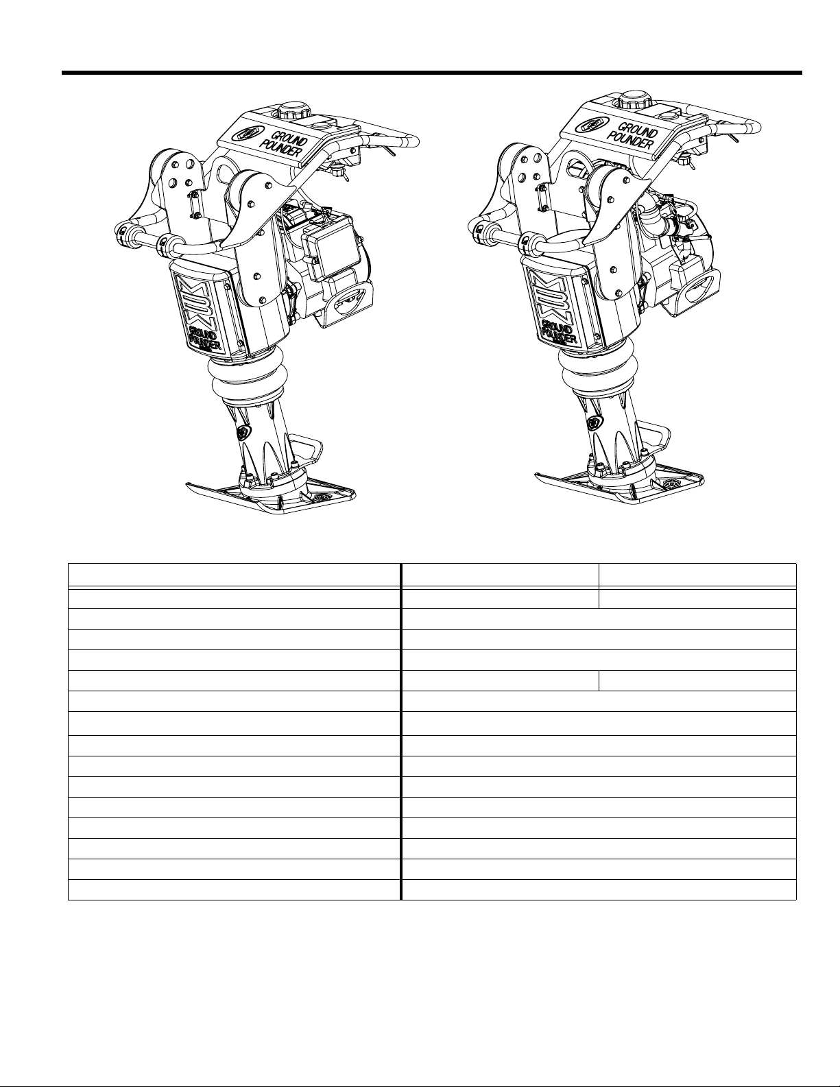
R442
This manual covers the following serial numbers
and higher for each model listed:
R442H...........................4420600
SMART RAMMERS
MBW, Inc.
250 Hartford Rd • PO Box 440
Slinger, WI 53086-0440
Phone: (262) 644-5234
Fax: (262) 644-5169
Email: mbw@mbw.com
Website: www.mbw.com
MBW (UK) Ltd.
Units 2&3 CochraneStreet
Bolton BL3 6BN
England, UK
Phone: 44 (0) 01204 387784
Fax: 44 (0) 01204 387797
E-mail: mbwuk@btinternet.com
MBW FRANCE S.A.R.L.
Teléfono:+33 (0) 3 44 07 15 96
Fax: +33 (0) 3 44 07 41 28
L19904 / 03.19.N
©MBW, Inc. 2015
Printed in the USA

TABLE OF CONTENTS
SAFETY INFORMATION . . . . . . . . . . . . . . . . . 1
Introduction . . . . . . . . . . . . . . . . . . . . . . . . . . . . . . . . . 1
Safety Precautions . . . . . . . . . . . . . . . . . . . . . . . . . . . 1
Safety Decals . . . . . . . . . . . . . . . . . . . . . . . . . . . . . . . 1
SPECIFICATIONS. . . . . . . . . . . . . . . . . . . . . . . 3
OPERATION . . . . . . . . . . . . . . . . . . . . . . . . . . . 4
Introduction . . . . . . . . . . . . . . . . . . . . . . . . . . . . . . . . . 4
Before Starting & Operating . . . . . . . . . . . . . . . . . . . . 4
Starting Engine . . . . . . . . . . . . . . . . . . . . . . . . . . . . . . 4
Operating . . . . . . . . . . . . . . . . . . . . . . . . . . . . . . . . . . 4
Stopping Engine . . . . . . . . . . . . . . . . . . . . . . . . . . . . . 4
Lifting and Transporting . . . . . . . . . . . . . . . . . . . . . . . 4
MAINTENANCE . . . . . . . . . . . . . . . . . . . . . . . . 5
Maintenance Schedule . . . . . . . . . . . . . . . . . . . . . . . . 5
Fluid Levels. . . . . . . . . . . . . . . . . . . . . . . . . . . . . . . . . 5
Engine Maintenance . . . . . . . . . . . . . . . . . . . . . . . . . . 5
Engine Speed . . . . . . . . . . . . . . . . . . . . . . . . . . . . . . . 5
Checking Percussion System Oil . . . . . . . . . . . . . . . . 5
Changing Percussion System Oil . . . . . . . . . . . . . . . . 6
SERVICE . . . . . . . . . . . . . . . . . . . . . . . . . . . . . .7
Torque Chart . . . . . . . . . . . . . . . . . . . . . . . . . . . . . . . 7
Service Tools . . . . . . . . . . . . . . . . . . . . . . . . . . . . . . . 7
General. . . . . . . . . . . . . . . . . . . . . . . . . . . . . . . . . . . . 7
Handle Removal. . . . . . . . . . . . . . . . . . . . . . . . . . . . . 7
Engine Removal . . . . . . . . . . . . . . . . . . . . . . . . . . . . . 7
Clutch Removal . . . . . . . . . . . . . . . . . . . . . . . . . . . . . 8
Gearbox Removal . . . . . . . . . . . . . . . . . . . . . . . . . . . 8
Gearbox Disassembly . . . . . . . . . . . . . . . . . . . . . . . . 8
Gearbox Assembly . . . . . . . . . . . . . . . . . . . . . . . . . . . 9
Lower Unit Disassembly. . . . . . . . . . . . . . . . . . . . . . 10
Lower Unit Assembly . . . . . . . . . . . . . . . . . . . . . . . . 10
Gearbox and Lower Unit Assembly . . . . . . . . . . . . . 11
Parts Replacement Cycles and Tolerances . . . . . . . 12
REPLACEMENT PARTS. . . . . . . . . . . . . . . . .13
Gearbox Assembly . . . . . . . . . . . . . . . . . . . . . . . . . . 14
Lower Unit Assembly . . . . . . . . . . . . . . . . . . . . . . . . 16
Gearbox and Lower Unit Assembly . . . . . . . . . . . . . 18
Handle Assembly . . . . . . . . . . . . . . . . . . . . . . . . . . . 20
Engine Assembly . . . . . . . . . . . . . . . . . . . . . . . . . . . 22
WARRANTY . . . . . . . . . . . . . . . . . . . . . . . . . . 24
CALIFORNIA PROPOSITION 65 WARNING
WARNING
Engine exhaust and some of its constituents
and dust produced during the use of this
product contain chemicals known in the state
of California to cause cancer, birth defects,
and other reproductive harm.
SAFETY INFORMATION
WARNING
CAUTION
Introduction
This Safety Alert Symbol is used to call attention
to items or operations which may be dangerous
to those operating or working with this equipment.
The symbol can be found throughout this manual
and on the unit. Please read these warnings and cautions,
along with all decals, carefully before attempting to operate
the unit. Make sure every individual who operates or works
with this equipment is familiar with all safety precautions.
GENERAL WARNING. Indicates information
important to the proper operation of the equipment.
Failure to observe may result in damage to the
equipment and/or severe bodily injury or death.
GENERAL CAUTION. Indicates information
important to the proper operation of the equipment.
Failure to observe may result in damage to the
equipment.
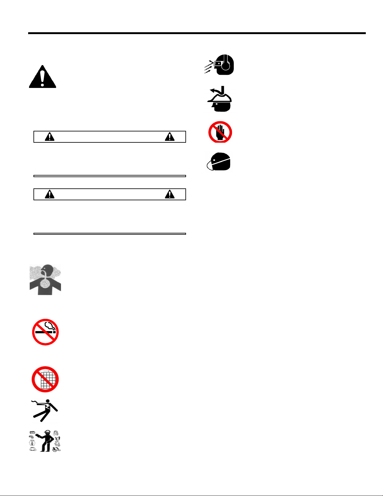
Safety Precautions
LETHAL EXHAUST GAS: An internal
combustion engine discharges carbon
monoxide, a poisonous, odorless, invisible
gas. Death or serious illness may result if
inhaled. Operate only in a properly ventilated
area. NEVER OPERATE IN A CONFINED
AREA!
DANGEROUS FUELS: Use extreme caution
when storing, handling and using fuels, as
they are highly volatile and explosive in vapor
state. Do not add fuel while engine is running.
Stop and cool the engine before adding fuel.
DO NOT SMOKE!
SAFETY GUARDS: It is the owner's
responsibility to ensure that all guards and
shields are in place and in working order.
IGNITION SYSTEMS: Breakerless, magneto,
and battery ignition systems can cause severe
electrical shocks. Avoid contacting these units
or their wiring.
SAFE DRESS: Do not wear loose clothing,
rings, wristwatches, etc. near machinery.
NOISE PROTECTION: Wear OSHA specified
hearing protection devices.
EYE PROTECTION: Wear OSHA specified
eye shields, safety glasses, and sweat bands.
FOOT PROTECTION: Wear OSHA specified
steel-tipped safety shoes.
HEAD PROTECTION: Wear OSHA specified
safety helmets.
OPERATOR: Keep children and bystanders
off and away from the equipment.
DUST PROTECTION
handling of stone, concrete, masonry, metal
and other materials may generate dust, mist
and fumes containing chemicals such as
silica, known to cause serious or fatal injury or illness, such
as respiratory disease, silicosis, cancer, birth defects, or
other reproductive harm.
• Control dust, mist and fumes at the source where possible.
Water should be used to control dust whenever feasible.
• Use good work practices and follow the recommendations
of the manufacture, OSHA/NIOSH and other occupational
trade associations.
• When hazards cannot be eliminated the operator and any
bystanders should always wear a OSHA specified respirator
for materials being handled.
REFERENCES: For details on safety rules and regulations
in the United States, contact your local Occupational Safety
and Health Administration (OSHA) office. Equipment
operated in other countries must be operated and serviced
in accordance and compliance with any and all safety
requirements of that country. The publication of these safety
precautions is done for your information. MBW does not by
the publication of these precautions, imply or in any way
represent that these are the sum of all dangers present near
MBW equipment. If you are operating MBW equipment, it is
your responsibility to insure that such operation is in full
accordance with all applicable safety requirements and
codes. All requirements of the United States Federal
Occupational Safety and Health Administration Act must be
met when operated in areas that are under the jurisdiction
of that United States Department.
: Machining, crushing or
Safety Decals
Carefully read and follow all safety decals. Keep them in
good condition. If decals become damaged, replace as
required. If repainting the unit, replace all decals. Decals are
available from authorized MBW distributors. Order the decal
set listed on the following page(s).
- 1 -
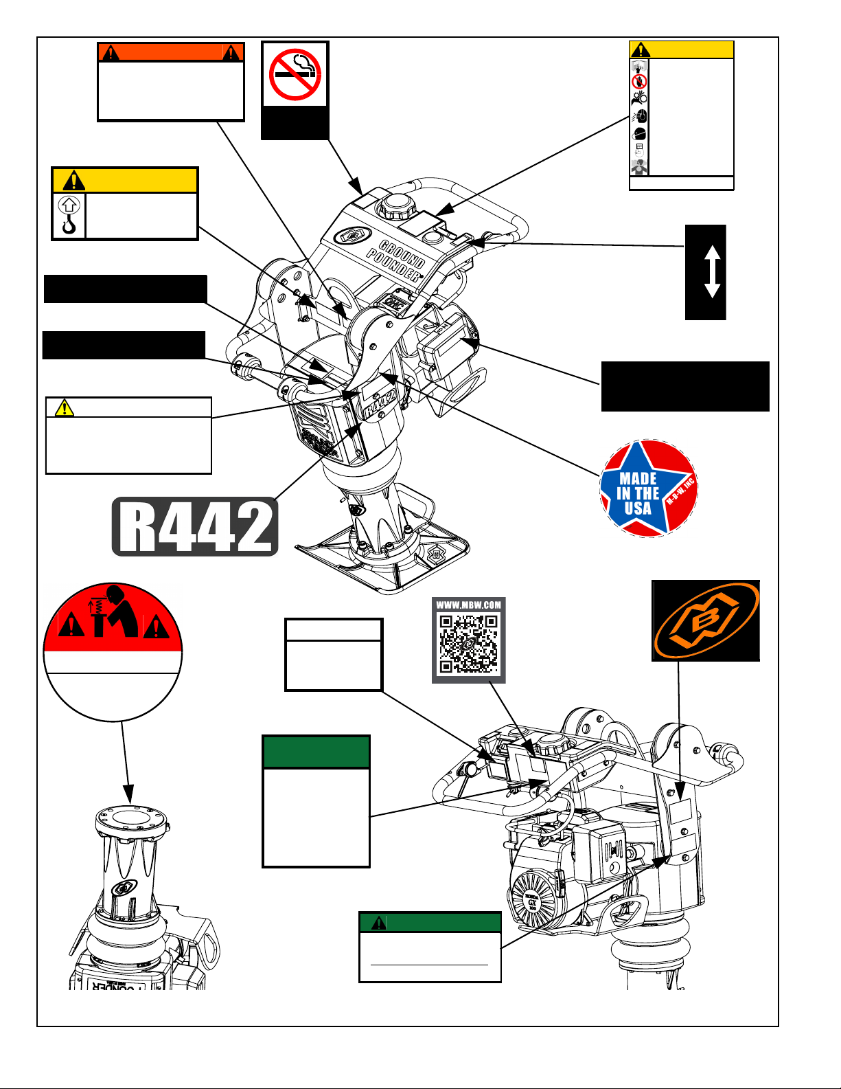
DANGER
Compressed spring could cause severe injury.
See manual for disassembly instructions.
La resorte comprimida podría causar la
herida severa. Consulte el libro para
ver el desmontaje correcto.
PELIGRO
01
32
6
U.S. PATENT 8,202,022
20425 RAMMER
CAUTION
Machine is top heavy and could
fall if not lifted from this bar.
R422 = 138 lb (63 kg)
R442 = 150 lb (68 kg)
R482/483 = 177 lb (80 kg)
20258
19791
WARNING
OPERATION OF THIS EQUIPMENT MAY
CREATE SPARKS THAT CAN START FIRES
AROUND DRY VEGETATION. A SPARK
ARRESTER MAY BE REQUIRED. THE
OPERATOR SHOULD CONTACT LOCAL FIRE
AGENCIES FOR LAWS OR REGULATIONS
RELATING TO FIRE PREVENTION
UNLEADED
GASOLINE
14781
Failure to comply could result in serious bodily
injury.
13483
CAUTION
STOP
Read Operating Instructions before
operating this piece of equipment.
Keep unauthorized and untrained
people away from this equipment.
ROTATING & MOVING PARTS!
Make sure all guards and safety
devices are in place.
Wear OSHA approved hearing
protection, foot protection, eye
protection and head protection.
Avoid breathing dust from operating
machine, wear OSHA specified dust
mask/respirator.
SHUT OFF the motor before servicing
or cleaning.
DO NOT RUN in an enclosed area.
The engine produces carbon
monoxide, a POISONOUS GAS.
581
,'/(
7
+
5
2
7
7
/
(
$,5&/($1(5,16758&7,216
&/($1(/(0(17'$,/<025(2)7(181'(5'867<&21',7,216
7$3(/(0(17/,*+7/<21$)/$7685)$&(,)'867'2(6127'523
2))($6,/<25,)(/(0(17,6%(1725&586+('
5(3/$&(,7
:$51,1*'212723(5$7((1*,1(:,7+287$,5&/($1(5
(/(0(17,17(51$/'$0$*(:,//5(68/7
01064
5(0,1'(5
&+(&.(1*,1(2,/'$,/<
(1*,1(0867%(/(9(/
OPTIMAL OPERATING
SPEED
420-421/422...3500 RPM
440/442..........3500 RPM
480-481..........3200 RPM
482-483..........3200 RPM
15287
OPERATING
INSTRUCTIONS
1. Check fuel level.
2. Open fuel valve.
3. Set throttle at idle postion.
4. Choke engine. A warm engine may not need
to be choked.
5. Pull starter rope.
6. After starting, open choke gradually and let
engine warm up at idle.
7. To start compacting: open throttle fully.
8. To stop: return throttle to idle and allow engine
to run for a few minutes before turning off.
9. Turn engine switch to off and close fuel valve.
14773
20258
U.S. PATENT 8,057,125
19895 RAMMER
21743
WARNING
Operating, servicing and maintaining this equipment
can expose you to chemicals, including engine
exhaust, phthalates and lead, which are known to the
state of California to cause cancer and birth defects or
other reproductive harm. Avoid breathing engine
exhaust. Do not operate equipment in confined areas.
For more information go to
www.P65Warnings.ca.gov
21820
19895
20425
21820
19791
14781
13483
14770
06079
01326
Safety Decals (Decal Set #17777)
12500
21445
01064
15287
21743
14773
15137
- 2 -
SPECIFICATIONS
++
+$
442H/442H12 442HA
Operating Weight - lbs(kg) 150 (68) 154 (70)
Height - in(cm) 41 (104)
Width - in(cm) 15 (38)
Length - in(cm) 29 (74)
Engine Honda GX100/GXR120 Honda GX100
Shoe (W x L) in (cm) 11 x 13 (28 x 33)
1
Operating Noise Level
Compaction Force lbf (kN) 3800 (16.9)
Travel Speed ft/min(m/min) 55 (16.8)
Compaction Area sqft/hr (sqm/hr) 3025 (281)
Percussion Rate blows/min up to 720
Engine Speed rpm 3500
Fuel Capacity - gal(L) 1.1 (4.2)
Gearbox Oil Capacity ounces (L) 18 (0.5)
Engine Oil Capacity ounces (L) 9.6 (0.28)
Specifications subject to change without notice
1. Noise levels are taken at the operating position and are based on operating conditions. Background noise will increase noise levels.
2. Noise level is operating on loose gravel surface. Hearing protection may be required.
3. Not all product variations shown.
dBa
93 dBA
- No universal method or formula has been accepted for determining “Compaction Force”. All manufactures employ their
own method or formula.
- 3 -

OPERATION
CAUTION
WARNING
WARNING
Introduction
MBW equipment is intended for use in very severe
applications. They are powered by four cycle engines and
are available in different sizes and a selection of engines.
This parts manual contains only standard parts. Variations
of these parts as well as other special parts are not included.
Contact your local MBW distributor for assistance in
identifying parts not included in this manual.
Before Starting & Operating
• REMEMBER! It is the owner’s responsibility to
communicate information on the safe use and proper
operation of this unit to the operators.
• Review ALL of the Safety Precautions listed on page 1 of
this manual.
• Familiarize yourself with the operation of the machine
and confirm that all controls function properly.
• Know how to STOP the machine in case of an
emergency.
• Make sure hands, feet, and clothing are at a safe
distance from any moving parts.
4. Choke engine if necessary (you may not need to
choke a warm engine).
5. Pull starter rope repeatedly until engine starts.
6. Move choke lever to open position.
7. Allow engine to warm up for one or two minutes.
Operating
1. Familiarize yourself with the balance of the rammer
before using it in job conditions. Due to the inherent
design, the machine is top heavy and could tip over.
2. After the engine warms up, open the throttle fully for
normal operation.
3. On uneven terrain, pushing down on the handle will
aid climbing ability.
Do not bear down (body weight of operator) on
the machine.
4. After 3 passes, the rammer may have more kick
back, this is an indication that ideal compaction is
being reached.
• OIL LEVEL - Check the oil level in the engine. For more
information see “Lubrication” under the respective
engine’s “Owners Manual” or the Maintenance section of
this manual.
• AIR CLEANER - Check to ensure element is in good
condition and properly installed.
• FUEL SUPPLY - The engines on MBW equipment
require an automotive grade of clean, fresh, unleaded
gasoline.
• FUEL FILTER - If clogged or damaged, replace.
Starting Engine
For detailed instructions refer to the engine “Owner’s
Manual”.
1. Open fuel valve.
2. Turn engine switch to “ON”.
3. Set throttle to idle.
The engine speed must NOT be high enough to
engage the clutch.
Stopping Engine
1. Move throttle to idle position.
2. Let engine idle for one or two minutes.
3. Turn switch on engine to “STOP” position.
4. Turn off fuel valve.
Always stop the engine before:
Adding fuel.
Leaving the equipment unattended for any
amount of time.
Before making any repairs or adjustments to the
machine.
Lifting and Transporting
1. The unit may be lifted by the handle and engine
guard.
2. The unit should be transported laying face down
3. Secure it in place by the handle and shoe. DO NOT
lay the unit on its sides or face up during transport.
- 4 -

MAINTENANCE
WARNING
CAUTION
Always exercise the stopping procedure before
servicing or lubricating the unit.
After servicing the unit, replace and fasten all
guards, shields, and covers to their original
positions before resuming operation.
Always verify fluid levels and check for leaks after
changing fluids.
Do not drain oil onto ground, into open streams,
or down sewage drains.
Maintenance Schedule
SYSTEM MAINTENANCE DAILY
Air Cleaner Check and clean X
Engine Refer to engine operator/owner manual X
Hardware
In Line Fuel Filter Replace XX
Percussion
System
Shockmounts Check for cracks or deterioration X
Spark Plug Replace XX
Check and tighten as needed
Check oil level X
Change oil
2
1
EVERY 25
HOURS
XX
EVERY 300
HOURS
XX
YEARLY
1. Check all hardware after the first 5 hours of use, then follow the maintenance schedule.
2. Change oil in lower unit after the first 50 hours of operation, then follow the maintenance schedule.
Fluid Levels
SYSTEM FLUID VOLUME RECOMMENDED OIL
Percussion System 18 oz SF SAE 10W-30 Motor Oil
Engine Refer to engine operator/owner manual
Engine Maintenance
Refer to the engine owner’s manual for maintenance
intervals and procedures.
• Check and clean the air cleaner element at least once
daily, The air cleaner has a foam pre-cleaner that can be
washed.
• Check the engine oil level by removing the dipstick (the
engine must be level). The oil level should be between
the marks on the dipstick. See the “Check Engine Oil”
section of the engine “Owner’s Manual” for information.
• See the “Change Engine Oil” section of the engine
“Owner’s Manual” for information on the oil change
intervals.
Engine Speed
Engine speed is factory set according to the speed listed in
the SPECIFICATIONS section of this manual. Refer to
the engine owners manual for procedure on setting
operating speed if necessary.
Checking Percussion System Oil
Refer to Lower Unit Assembly, page 16.
The rammer percussion system and gearbox are lubricated
by an oil mist which is formed and carried throughout the
rammer by a pumping action in the machine's lower system.
1. Before daily operation, place the rammer on a flat
surface and check the oil level in the glass sight (#8)
on the spring box guard (#13).
- 5 -

2. If the oil is not visible in the sight gauge, add oil as
required. See Fluid Levels for recommended type of
oil.
Changing Percussion System Oil
3. With the handle still on the ground, remove the four
hex head flange screws (#8) holding the cover (#2) to
the gearbox (#4).
4. Remove the cover, the cover gasket (#3), and the
dowel pins (#1) from the gearbox.
Refer to Lower Unit Assembly, page 16.
1. Remove the drain plug (#4) below the sight glass (#8)
on the back of the spring box guard (#13).
2. Place an oil drain pan behind the shoe and tip the
rammer back so the handle is on the ground.
Refer to Gearbox and Lower Unit Assembly, page 18.
5. Tip the unit forward and drain any oil into an oil pan.
6. After the oil has drained out, replace the dowel pins,
gasket, and cover and secure with the four hex head
flange screws.
7. Tip the rammer onto it’s face and fill according to the
Fluid Levels section in this manual.
8. Replace the drain plug (page 16, #4).
- 6 -
 Loading...