

MBW GPR77 User Manual
OPERATOR’S SAFETY
AND SERVICE MANUAL
GPR65,
GPR68 &
GPR77
This manual covers the following serial numbers
and higher for each model listed:
GPR65. . . . . . . . . . . . . . . . . . . . 6500001
GPR68. . . . . . . . . . . . . . . . . . . . 6800001
GPR77. . . . . . . . . . . . . . . . . . . . 7700010
REVERSIBLE PLATES
MBW, Inc.
250 Hartford Rd • PO Box 440
Slinger, WI 53086-0440
Phone: (262) 644-5234
Fax: (262) 644-5169
Email: mbw@mbw.com
Website: www.mbw.com
MBW (UK) Ltd.
Units 2 & 3 Cochrane Street
Bolton BL3 6BN, England
Phone: 01204 387784
Fax: 01204 387797
MBW FRANCE S.A.R.L.
Z.A. d’Outreville
11 rue Jean Baptiste Néron,
60540 BORNEL, France
E-mail: mbwfrance@free.fr
Website: www.mbw.com
Phone: +33 (0) 3 44 07 15 96
Fax: +33 (0) 3 44 07 41 28
L16456 / 09.14.N
©MBW, Inc. 2004
Printed in the USA

TABLE OF CONTENTS
Safety Information . . . . . . . . . . . . . . . . . . . . . . 1
Introduction . . . . . . . . . . . . . . . . . . . . . . . . . . . . . . . . . 1
Safety Precautions . . . . . . . . . . . . . . . . . . . . . . . . . . . 1
Safety Decals . . . . . . . . . . . . . . . . . . . . . . . . . . . . . . . 1
Safety Decal Set #16031 . . . . . . . . . . . . . . . . . . . . . . 3
Specifications. . . . . . . . . . . . . . . . . . . . . . . . . . 4
Operation . . . . . . . . . . . . . . . . . . . . . . . . . . . . . 5
Introduction . . . . . . . . . . . . . . . . . . . . . . . . . . . . . . . . . 5
Before Starting & Operating . . . . . . . . . . . . . . . . . . . . 5
Starting Engine . . . . . . . . . . . . . . . . . . . . . . . . . . . . . . 5
Operating . . . . . . . . . . . . . . . . . . . . . . . . . . . . . . . . . . 5
Stopping Engine . . . . . . . . . . . . . . . . . . . . . . . . . . . . . 5
Maintenance . . . . . . . . . . . . . . . . . . . . . . . . . . . 6
Maintenance Schedule . . . . . . . . . . . . . . . . . . . . . . . . 6
Fluid Levels. . . . . . . . . . . . . . . . . . . . . . . . . . . . . . . . . 6
Engine Maintenance . . . . . . . . . . . . . . . . . . . . . . . . . . 6
Engine Speed . . . . . . . . . . . . . . . . . . . . . . . . . . . . . . . 6
Belt Adjustment. . . . . . . . . . . . . . . . . . . . . . . . . . . . . . 6
Exciter Oil Change Procedure . . . . . . . . . . . . . . . . . . 6
Checking the Shifter Cable . . . . . . . . . . . . . . . . . . . . . 7
Service. . . . . . . . . . . . . . . . . . . . . . . . . . . . . . . . 9
Torque Chart . . . . . . . . . . . . . . . . . . . . . . . . . . . . . . . 9
Replacing Shifter Cable Assembly . . . . . . . . . . . . . . . 9
Gas Engine Removal . . . . . . . . . . . . . . . . . . . . . . . . . 9
Diesel Engine Removal . . . . . . . . . . . . . . . . . . . . . . 10
Exciter Removal . . . . . . . . . . . . . . . . . . . . . . . . . . . . 10
Exciter Disassembly . . . . . . . . . . . . . . . . . . . . . . . . . 10
Actuator Disassembly. . . . . . . . . . . . . . . . . . . . . . . . 11
Shifter Disassembly . . . . . . . . . . . . . . . . . . . . . . . . . 11
Shifter Assembly . . . . . . . . . . . . . . . . . . . . . . . . . . . 11
Actuator Assembly . . . . . . . . . . . . . . . . . . . . . . . . . . 11
Exciter Assembly . . . . . . . . . . . . . . . . . . . . . . . . . . . 12
Parts Replacement Cycles and Tolerances . . . . . . . 13
Replacement Parts . . . . . . . . . . . . . . . . . . . . . 15
Actuator Assembly . . . . . . . . . . . . . . . . . . . . . . . . . . 16
Shifter Assembly . . . . . . . . . . . . . . . . . . . . . . . . . . . 18
Exciter Assembly . . . . . . . . . . . . . . . . . . . . . . . . . . . 20
Honda Main Assembly . . . . . . . . . . . . . . . . . . . . . . . 22
Diesel Main Assembly . . . . . . . . . . . . . . . . . . . . . . . 24
Handle Assembly . . . . . . . . . . . . . . . . . . . . . . . . . . . 26
Warranty . . . . . . . . . . . . . . . . . . . . . . . . . . . . . 28
CALIFORNIA PROPOSITION 65 WARNING
WARNING
Engine exhaust and some of its constituents are
known in the state of California to cause cancer, birth
defects, and other reproductive harm.
SAFETY INFORMATION
WARNING
CAUTION
Introduction
This Safety Alert Symbol is used to call attention
to items or operations which may be dangerous
to those operating or working with this
equipment. The symbol can be found
throughout this manual and on the unit. Please read these
warnings and cautions, along with all decals, carefully
before attempting to operate the unit. Make sure every
individual who operates or works with this equipment is
familiar with all safety precautions.
GENERAL WARNING. Indicates information
important to the proper operation of the
equipment. Failure to observe may result in
damage to the equipment and/or severe bodily
injury or death.
GENERAL CAUTION. Indicates information
important to the proper operation of the
equipment. Failure to observe may result in
damage to the equipment.
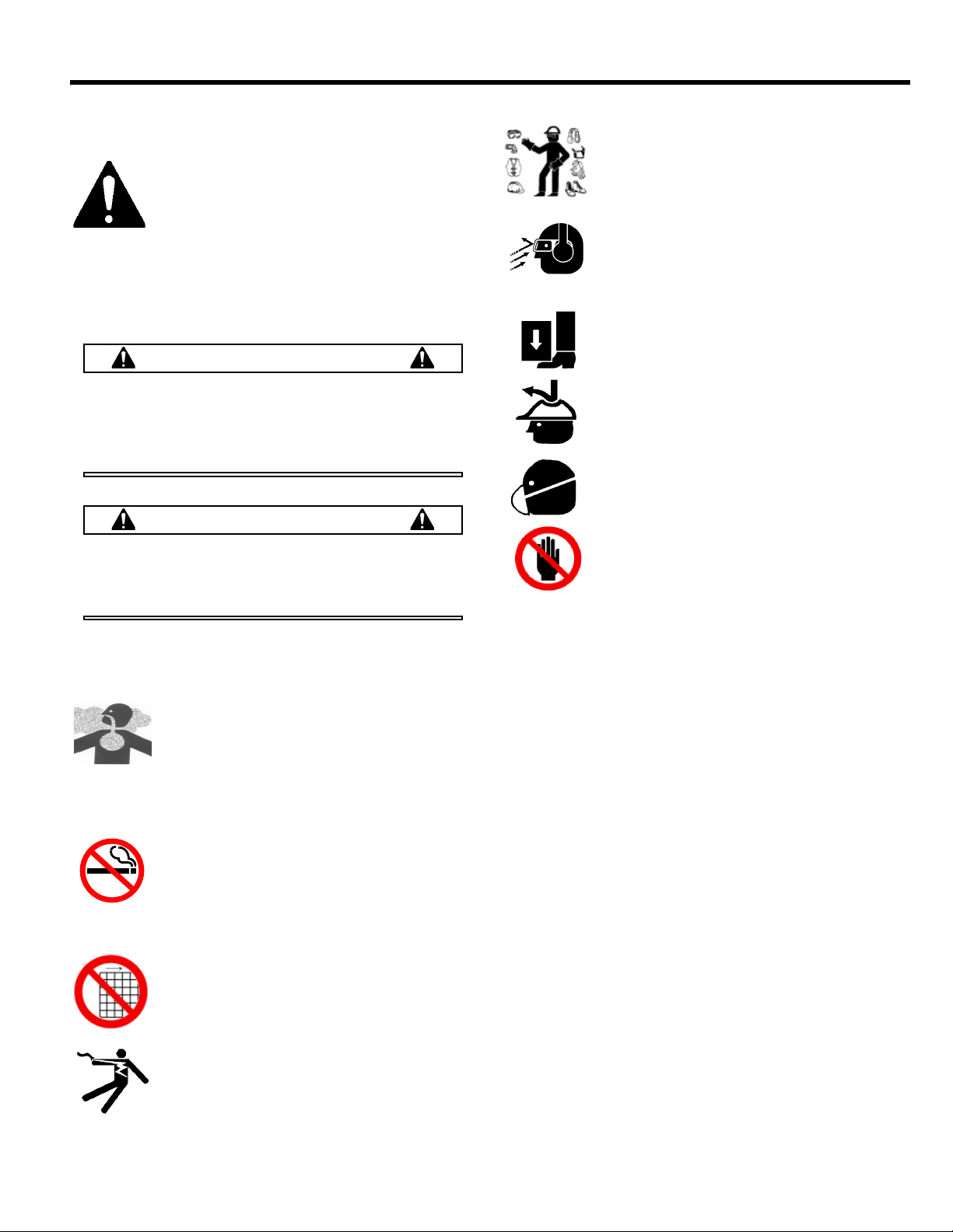
Safety Precautions
LETHAL EXHAUST GAS: An internal
combustion engine discharges carbon
monoxide, a poisonous, odorless, invisible
gas. Death or serious illness may result if
inhaled. Operate only in an area with proper
ventilation. NEVER OPERATE IN A
CONFINED AREA!
DANGEROUS FUELS: Use extreme caution
when storing, handling and using fuels, as
they are highly volatile and explosive in vapor
state. Do not add fuel while engine is running.
Stop and cool the engine before adding fuel.
DO NOT SMOKE!
SAFETY GUARDS: It is the owner's
responsibility to ensure that all guards and
shields are in place and in working order.
IGNITION SYSTEMS: Breakerless, magneto,
and battery ignition systems can cause severe
electrical shocks. Avoid contacting these
units or their wiring.
SAFE DRESS: Do not wear loose clothing,
rings, wristwatches, etc. near machinery.
NOISE PROTECTION: Wear OSHA specified
hearing protection devices.
EYE PROTECTION: Wear OSHA specified
eye shields, safety glasses, and sweat bands.
FOOT PROTECTION: Wear OSHA specified
steel-tipped safety shoes.
HEAD PROTECTION: Wear OSHA specified
safety helmets.
DUST PROTECTION: Wear OSHA specified
dust mask or respirator.
OPERATOR: Keep children and bystanders
off and away from the equipment.
REFERENCES: For details on safety rules and regulations
in the United States, contact your local Occupational Safety
and Health Administration (OSHA) office. Equipment
operated in other countries must be operated and serviced
in accordance and compliance with any and all safety
requirements of that country. The publication of these
safety precautions is done for your information. MBW does
not by the publication of these precautions, imply or in any
way represent that these are the sum of all dangers present
near MBW equipment. If you are operating MBW
equipment, it is your responsibility to insure that such
operation is in full accordance with all applicable safety
requirements and codes. All requirements of the United
States Federal Occupational Safety and Health
Administration Act must be met when operated in areas that
are under the jurisdiction of that United States Department.
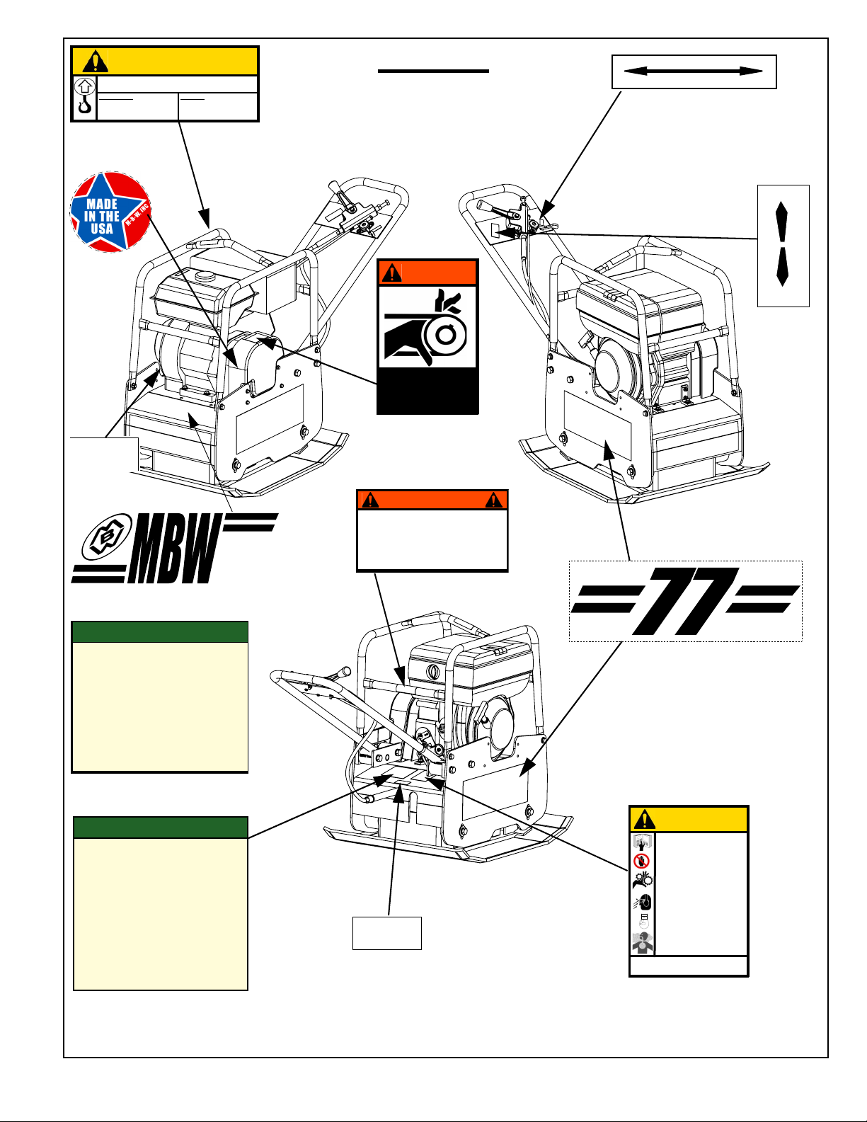
Safety Decals
Carefully read and follow all safety decals. Keep them in
good condition. If decals become damaged, replace as
required. If repainting the unit, replace all decals. Decals
are available from authorized MBW distributors. Order the
decal set listed on the following page(s).
- 1 -
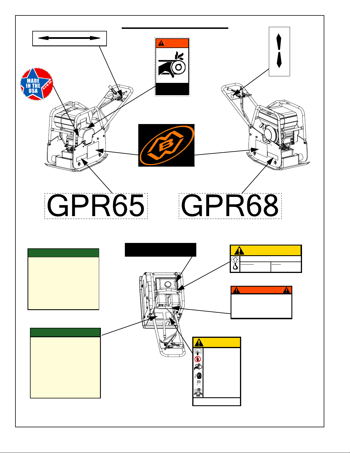
FORWARD
REVERSE
14665
RUN IDLE STOP
THROTTLE
15843
01064
16993
16994
UNLEADED GASOLINE
13481
CAUTION
17287
GPR65/68:
Gas = 330 lbs (149 kg)
Diesel = 360 lbs (163 kg)
Machine may fall and cause injury or damage if
lifted improperly. Lift by rollcage only.
GPR77:
Gas = 397 lbs (180 kg)
Diesel = 399 lbs (181 kg)
13483
CAUTION
Wear approved hearing protection,
foot protection, eye protection and
head protection.
STOP
Read the Operating Instructions
before operating this piece of
equipment.
Keep unauthorized and untrained
people away from this
equipment.
ROTATING & MOVING PARTS!
Make sure all guards and safety
devices are in place.
Failure to comply could result in serious
bodily injury.
SHUT OFF the motor before servic-
ing or cleaning.
DO NOT RUN in an enclosed area.
The engine produces carbon
monoxide, a POISONOUS GAS.
1. Check engine oil level.
2. Open fuel valve.
3. Choke engine. A warm engine may not need to be
choked.
4. Open throttle part way.
5. Pull starter rope.
6. After starting: open choke, return throttle to idle
position.
7. During operation, when excessive kickback is
noticed, maximum compaction has been reached.
8. To stop, return throttle to the idle position, use
engine stop switch, close fuel valve.
GASOLINE PLATE
OPERATING INSTRUCTIONS
15866
1. Check engine oil level.
2. Check fuel level.
3. Set engine speed control in the middle position.
4. Move decompression lever (if equipped) to the up
position. (Located on top of the engine)
5. Use key (if equipped) or starting handle to start
engine (Refer to engine instruction book for proper
“Manual Starting” procedure.)
6. After starting return engine speed control to the idle
position and allow engine to reach operation
temperature.
7. During operation run engine at full throttle, when
excessive kickback is noticed maximum compaction
has been reached.
8. To stop, return throttle to the idle position and allow
engine to idle for one minute then move control to
stop position.
DIESEL PLATE
OPERATING INSTRUCTIONS
15832
19791
WARNING
OPERATION OF THIS EQUIPMENT MAY
CREATE SPARKS THAT CAN START FIRES
AROUND DRY VEGETATION. A SPARK
ARRESTER MAY BE REQUIRED. THE
OPERATOR SHOULD CONTACT LOCAL FIRE
AGENCIES FOR LAWS OR REGULATIONS
RELATING TO FIRE PREVENTION
#15843 Diesel only
GPR65 & GPR68
#14465
#12500
#13484
#15874 (not included in kit)
OR
#16994 (not included in kit)#16993 (not included in kit)
#13481 Gas only
OR
Safety Decals #16031
#15866 Gas only
#15832 Diesel only
#17287
#19791
#13483
- 2 -
CAUTION
17287
GPR65/68:
Gas = 330 lbs (149 kg)
Diesel = 360 lbs (163 kg)
Machine may fall and cause injury or damage if
lifted improperly. Lift by rollcage only.
GPR77:
Gas = 397 lbs (180 kg)
Diesel = 399 lbs (181 kg)
GPR77
19131
19133
12573
WARNING
ROTATING PARTS
can crush and cut.
Keep hands away!
ENGINE
OIL DRAIN
15845
19791
WARNING
OPERATION OF THIS EQUIPMENT MAY
CREATE SPARKS THAT CAN START FIRES
AROUND DRY VEGETATION. A SPARK
ARRESTER MAY BE REQUIRED. THE
OPERATOR SHOULD CONTACT LOCAL FIRE
AGENCIES FOR LAWS OR REGULATIONS
RELATING TO FIRE PREVENTION
GPR77
1. Check engine oil level.
2. Open fuel valve.
3. Choke engine. A warm engine may not need to be
choked.
4. Open throttle part way.
5. Pull starter rope.
6. After starting: open choke, return throttle to idle
position.
7. During operation, when excessive kickback is
noticed, maximum compaction has been reached.
8. To stop, return throttle to the idle position, use
engine stop switch, close fuel valve.
GASOLINE PLATE
OPERATING INSTRUCTIONS
15866
1. Check engine oil level.
2. Check fuel level.
3. Set engine speed control in the middle position.
4. Move decompression lever (if equipped) to the up
position. (Located on top of the engine)
5. Use key (if equipped) or starting handle to start
engine (Refer to engine instruction book for proper
“Manual Starting” procedure.)
6. After starting return engine speed control to the idle
position and allow engine to reach operation
temperature.
7. During operation run engine at full throttle, when
excessive kickback is noticed maximum compaction
has been reached.
8. To stop, return throttle to the idle position and allow
engine to idle for one minute then move control to
stop position.
DIESEL PLATE
OPERATING INSTRUCTIONS
15832
13483
CAUTION
Wear approved hearing protection,
foot protection, eye protection and
head protection.
STOP
Read the Operating Instructions
before operating this piece of
equipment.
Keep unauthorized and untrained
people away from this
equipment.
ROTATING & MOVING PARTS!
Make sure all guards and safety
devices are in place.
Failure to comply could result in serious
bodily injury.
SHUT OFF the motor before servic-
ing or cleaning.
DO NOT RUN in an enclosed area.
The engine produces carbon
monoxide, a POISONOUS GAS.
ENGINE
OIL DRAIN
15845
RUN IDLE STOP
THROTTLE
15843
FORWARD
REVERSE
14665
#15843 Diesel
#17287
#12500
#15845
#17449 Gasoline
#14665
#12573
OR
Safety Decal Set #16031
#15866 Gas only
#15832 Diesel only
#19131
#19791
#19133
#15845
#13483
- 3 -
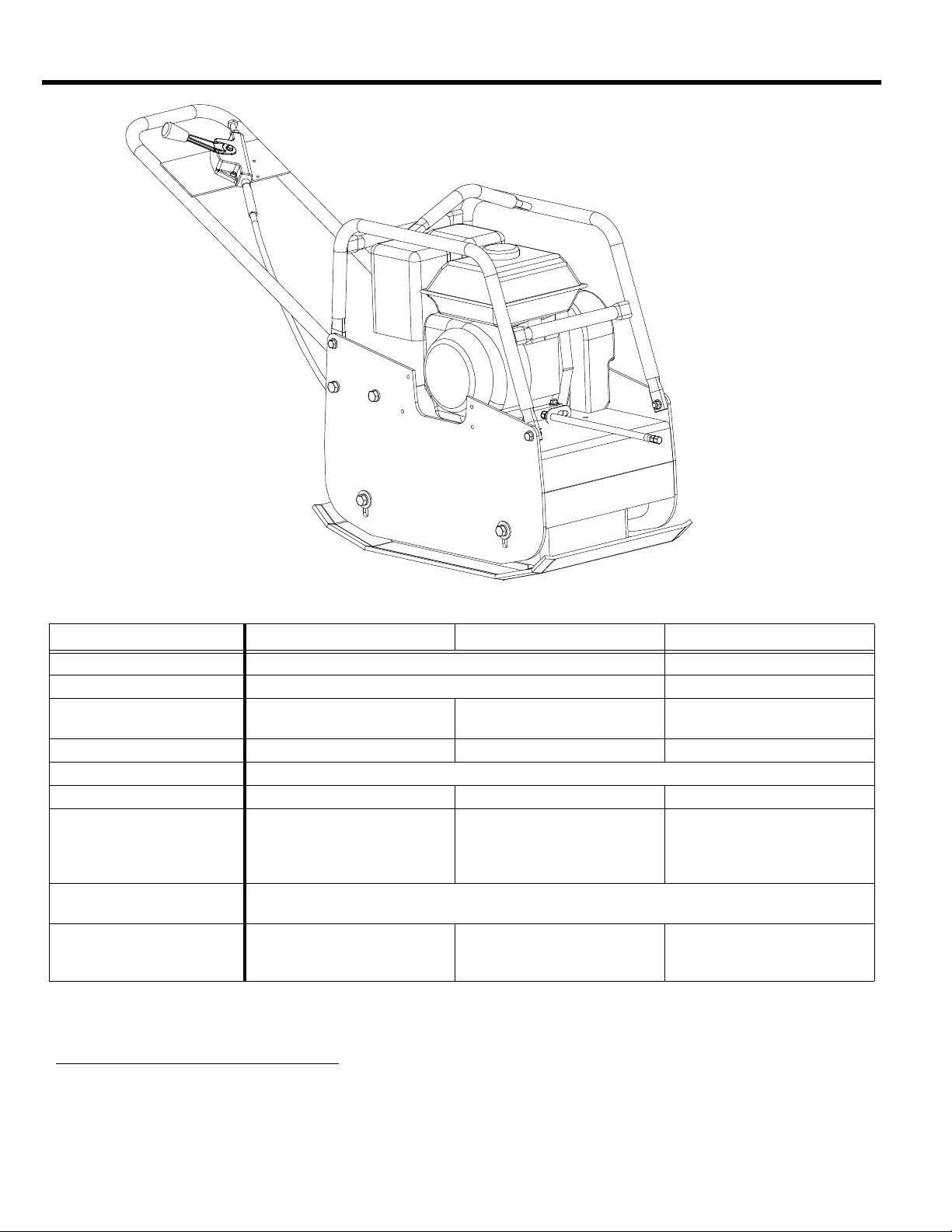
SPECIFICATIONS
GPR65 GPR68 GPR77
Centrifugal Force 6000 lbf (27 kN) 7775 lbf (34 kN)
Exciter vpm 4400 vpm 4700 vpm
Width & Length
Travel Speed 92 ft./min. (28 m/min.) 88 ft./min. (27 m/min.) 86 ft./min. (26 m/min.)
Compaction Depth Up to 22 in (56 cm) See Note Below
Compaction Area 6900 sq. ft./hr (640 sq. m/hr) 7920 sq. ft./hr (736 sq. m/hr) 9460 sq. ft./hr (879 sq. m/hr)
Operating Weight
Engine Speed
Engine
Specifications subject to change without notice
Compaction depth: Clean sand & optimum moisture.
MBW recommends that lifts not exceed 12” (31 cm)
15 in x 26.3 in
(381mm x 668mm)
Honda - 325 lbs (147 kg)
Hatz-365 lbs (165 kg)
Honda GX160
Hatz 1B20
18 in x 26.3 in
(457 mm x 668 mm)
Honda - 330 lbs (150 kg)
Robin - 330lbs (150 kg)
Hatz- 370 lbs (168 kg)
Honda 3400 RPM
Hatz 3600 RPM
Honda GX160
Hatz 1B20
ROBIN EX17
22 in x 26.3 in
(559 mm x 668 mm)
Honda - 397 lbs (180 kg)
Hatz- 399 lbs (181 kg)
Honda GX270
Hatz 1B20
- 4 -

OPERATION
WARNING
Introduction
MBW equipment is intended for use in very severe
applications. They are powered by four cycle engines and
are available in different sizes and a selection of engines.
This parts manual contains only standard parts. Variations
of these parts as well as other special parts are not included.
Contact your local MBW distributor for assistance in
identifying parts not included in this manual.
Before Starting & Operating
• REMEMBER! It is the owner’s responsibility to
communicate information on the safe use and proper
operation of this unit to the operators.
• Review ALL of the Safety Precautions listed on page 1 of
this manual.
• Familiarize yourself with the operation of the machine
and confirm that all controls function properly.
• Know how to STOP the machine in case of an
emergency.
• Make sure hands, feet, and clothing are at a safe
distance from any moving parts.
• OIL LEVEL - Check the oil level in the engine. For more
information see “Lubrication” under the respective
engine’s “Owners Manual” or the Maintenance section of
this manual.
• AIR CLEANER - Check to ensure element is in good
condition and properly installed.
7. Allow engine to warm up for one or two minutes.
Diesel Engine-
1. When starting the engine, the THROTTLE LEVER
ON THE HANDLE MUST BE IN AN IDLE POSITION.
2. The engine has an automatic decompression
system, however it is recommended to slowly pull the
starter rope until you feel a slight resistance. Let the
starter rope recoil completely and then pull the starter
rope quickly, do not jerk the starter handle, until the
engine starts.
3. Let the starter rope recoil completely and pull the
starter rope quickly to start the engine.
4. After the engine starts make sure the throttle lever is
in the idle position.
5. Let the engine warm up in the idle position for one or
two minutes.
Operating
1. After the engine warms up, fully open the throttle.
2. Never leave the compactor idling unattended. The
MBW Reversible plate compactor is designed to
move without operator application of the control
lever.
3. The number of passes needed to reach the
compaction level desired will depend on soil type and
moisture content. Maximum compaction of the soil
has been reached when excessive kickback is
noticed in the compactor.
Stopping Engine
• FUEL SUPPLY - The engines on MBW equipment
require an automotive grade of clean, fresh, unleaded
gasoline.
• FUEL FILTER - If clogged or damaged, replace.
Starting Engine
Gasoline Engine-
1. Open fuel valve.
2. Turn engine switch to “ON”.
3. Set throttle to idle.
4. Choke engine if necessary (you may not need to
choke a warm engine).
5. Pull starter rope repeatedly until engine starts.
6. Move choke lever to open position.
1. Move throttle to idle position.
2. Let engine idle for one or two minutes.
3. Turn switch on engine to “STOP” position (throttle
stop position on diesel engines). For detailed
instructions refer to the Engine Manual.
4. Turn off fuel valve.
Always stop the engine before:
Adding fuel.
Leaving the equipment unattended for any
amount of time.
Before making any repairs or adjustments to the
machine.
- 5 -

MAINTENANCE
WARNING
CAUTION
Always exercise the stopping procedure before
servicing or lubricating the unit.
After servicing the unit, replace and fasten all
guards, shields, and covers to their original
positions before resuming operation.
Always verify fluid levels and check for leaks after
changing fluids.
Collect and dispose of all hazardous materials
according to local legislation. Do not drain oil
onto ground, into open streams, or down sewage
drains.
Maintenance Schedule
SYSTEM MAINTENANCE EACH USE
Engine Refer to engine operator/owner manual X
Exciter Check oil level X
Check for oil leaks X
Change oil XX
Tighten Bolts
Hardware
Shockmounts Check for cracks or tears XX
1. Check all hardware after the first 5 hours of use, then follow the maintenance schedule.
Check and tighten as needed
1
1
EVERY 50
HOURS
XX
XX
EVERY 500
HOURS
YEARLY
Fluid Levels
SYSTEM FLUID VOLUME RECOMMENDED OIL
Exciter 15 oz
Engine Refer to engine operator/owner manual
1. MBW #01058---- 6-Pack (8 oz bottles)
MBW #17320---- 1 quart (32 oz)
Engine Maintenance
Refer to the engine owner’s manual for maintenance
intervals and procedures.
Engine Speed
1. The Honda engine should be set to an operating
speed of 3400 rpm. The Hatz engine should be set to
3600 rpm. Check the engine owner’s manual for the
procedure on setting the operating speed.
2. The idle speed must not exceed 1800 rpm. If the idle
speed is higher, the clutch may not disengage.
Check the engine owner’s manual for the procedure
on setting the idle speed.
MBW Ground Pounder
®
Exciter Oil
1
Belt Adjustment
1. Remove the Beltgaurd
2. Loosen (don’t remove) the (4) 1/2” hex head
capscrews securing the engine deck to the
baseplate.
3. Re-tension the belt by lifting the engine deck to
provide 3/8 - 1/2 inch of “play” on one side of the belt.
4. Retighten the (4) 1/2” hex head capscrews.
5. Reinstall the beltgaurd.
Exciter Oil Change Procedure
1. Let the machine cool.
2. Clean all visible debris from the machine before
servicing
- 6 -
3. Remove the (4) 1/2” hex head cap screws securing
WARNING
8
9
10
1
2
4
1
3
5
6
7
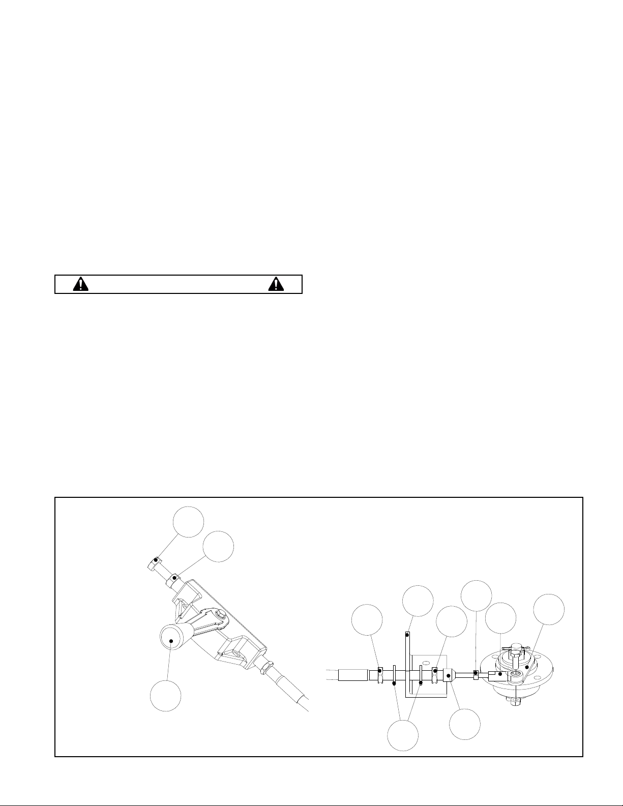
Figure 1 Shifter Cable
the engine deck to the baseplate.
4. Remove the (4) 1/4” hex head cap screws securing
the beltgaurd to the side plate on the engine deck and
remove the beltgaurd and belt.
5. Now is a good time to inspect and consider replacing
the v-belt.
6. Disconnect the shifter lever/cable from the handle
assembly by removing the (2) 1/4” bolts and nuts
securing the lever to the handle.
7. Lift the engine deck and handle assembly off of the
exciter assembly.
8. Now is a good time to inspect and consider replacing
the shock mounts.
9. Locate the drain plug to the left of the pulley and tilt
the exciter subassembly toward a drain pan to aid in
the removal of all used oil and particles.
13. Assemble the engine deck and handle assembly to
baseplate. (Do not tighten bolts)
14. Reconnect the shifter/shifter cable assembly to the
handle assembly.
15. Reinstall the belt and set tension per belt adjustment
procedure.
16. Start the engine and test the shifter for proper plate
motion. Stop engine.
17. Recheck the belt tension.
18. Reinstall the beltgaurd.
Checking the Shifter Cable
Refer to Figure 1 Shifter Cable, page 7.
1. Clean all visible debris from the machine before
servicing.
2. Remove the (4) 1/2” hex head capscrews securing
the engine deck to the baseplate.
Danger exciter oil can be scalding hot! Allow
exciter to cool down before draining. Collect all oil
drained and dispose of according to local
legislation.
10. Using a drain pan to catch the used exciter oil,
remove the socket head pipe plug and drain the oil.
(Examine the oil for metal chips as their presence
may indicate future problems.)
11. Tip the exciter subassembly away from the drain pan
and fill the exciter subassembly through the pipe plug
opening. Use only MBW® Exciter Oil. (Oil can be
purchased from your local MBW distributor).
12. Reinstall the socket head pipe plug using sealant.
3. Remove the (4) 1/4” hex head capscrews securing
the beltguard to the side plate on the engine deck and
remove the beltguard and the belt.
4. Disconnect the shifter handle from the handle by
removing the (2) 1/4” socket head capscrews.
5. Separate the engine deck and the baseplate.
6. Push the shifter lever (item #8) into the forward
position and hold.
7. Turn the exciter pulley counterclockwise and feel for
resistance.
8. Repeat steps 6 & 7 for the reverse position.
9. Repeat steps 6, 7 and 8.
- 7 -
 Loading...