

MBW CG200 User Manual
CONCRETE CURB
Units 2 & 3 Cochrane street
Bolton
BL3 6BN
AND GUTTER
SLIPFORM PAVER
OPERATING INSTRUCTIONS
C100
C101
CG200
It is the OWNER'S RESPONSIBILITY to communicate information on the
SAFE USE and OPERATION of this machine to the operators!
L11547/ 7.06 E
MBW inc copyright 2006
Printed in U.S.A.
MBW INC.
250 HARTFORD ROAD P.O. BOX 440
SLINGER, WI 53086-0440
PHONE: (262) 644-5234 FAX (262) 644-5169
MBW CORPORATE INTERNET ADDRESS
E-MAIL: mbw@mbw.com WEB SITE: www.mbw.com
IN ENGLAND:
MBW (UK) LIMITED
Phone: 01204 387784 FAX: 01204 387797

TABLE OF CONTENTS
FORWARD 1. . . . . . . . . . . . . . . . . . . . . . . . . . . . . . . . . . . . . . . . . . . . . . . .
MBW SLIPFORM PAVER PURCHASE AWARENESS 2. . . . . . . . . .
SAFETY PRECAUTIONS 3. . . . . . . . . . . . . . . . . . . . . . . . . . . . . . . . . . .
INTRODUCTION 4. . . . . . . . . . . . . . . . . . . . . . . . . . . . . . . . . . . . . . . . . . .
SAFETY NOTICE AND DECALS 5. . . . . . . . . . . . . . . . . . . . . . . . . . . . .
SAFETY DECAL LOCATIONS 6. . . . . . . . . . . . . . . . . . . . . . . . . . . . . . .
WARRANTY 8. . . . . . . . . . . . . . . . . . . . . . . . . . . . . . . . . . . . . . . . . . . . . . .
MBW WAREHOUSE LOCATIONS 9. . . . . . . . . . . . . . . . . . . . . . . . . . .
SPECIFICATIONS 10. . . . . . . . . . . . . . . . . . . . . . . . . . . . . . . . . . . . . . . . .
SERIAL # LOCATION 11. . . . . . . . . . . . . . . . . . . . . . . . . . . . . . . . . . . . . .
CONTROL PANEL DESCRIPTION 12. . . . . . . . . . . . . . . . . . . . . . . . . . .
CONTROL PANEL 13. . . . . . . . . . . . . . . . . . . . . . . . . . . . . . . . . . . . . . . . .
VIBRATOR CONTROLS 14. . . . . . . . . . . . . . . . . . . . . . . . . . . . . . . . . . . .
OPERATING INSTRUCTIONS 15. . . . . . . . . . . . . . . . . . . . . . . . . . . . . . .
STARTING THE ENGINE 16. . . . . . . . . . . . . . . . . . . . . . . . . . . . . . . . . . .
STOPPING THE ENGINE 17. . . . . . . . . . . . . . . . . . . . . . . . . . . . . . . . . . .
ASSEMBLY INSTRUCTIONS 18. . . . . . . . . . . . . . . . . . . . . . . . . . . . . . . .
ATTACHING HOPPER: 19. . . . . . . . . . . . . . . . . . . . . . . . . . . . . . . . . . .
ATTACHING MOLDS: 20. . . . . . . . . . . . . . . . . . . . . . . . . . . . . . . . . . . .
INSTALLING VIBRATORS: 21. . . . . . . . . . . . . . . . . . . . . . . . . . . . . . . .
CHANGING HOPPERS IN THE SIDE UNIT: 21. . . . . . . . . . . . . . . . .
INSTALLING SENSORS: 22. . . . . . . . . . . . . . . . . . . . . . . . . . . . . . . . .
SET-UP AND POURING INSTRUCTIONS 25. . . . . . . . . . . . . . . . . . .
JOB SITE SET-UP, SIDE DRIVE APPLICATIONS 25. . . . . . . . . . . .
JOB SITE SET-UP, 12" HOPPER, NO SIDE DRIVE 26. . . . . . . . . .
AUTOMATIC SENSOR SET-UP: 27. . . . . . . . . . . . . . . . . . . . . . . . . .
AUTOMATIC STEERING SENSOR ADJUSTMENTS: 28. . . . . . . . .
AUTOMATIC HEIGHT SENSOR ADJUSTMENTS: 30. . . . . . . . . . .
ADJUSTING THE HEIGHT LIMIT SWITCH: 31. . . . . . . . . . . . . . . . .
GRADING WITH THE PAVER BEFORE POURING: 32. . . . . . . . . . .
BEGIN POURING: 33. . . . . . . . . . . . . . . . . . . . . . . . . . . . . . . . . . . . . . .
SWITCHING STEERING SENSORS: 34. . . . . . . . . . . . . . . . . . . . . . .
ADJUSTMENTS WHILE POURING: 35. . . . . . . . . . . . . . . . . . . . . . . .
ADJUSTMENTS AFTER POURING: 35. . . . . . . . . . . . . . . . . . . . . . . .
OPERATING HINTS 36. . . . . . . . . . . . . . . . . . . . . . . . . . . . . . . . . . . . . . . .
PERIODIC MAINTENANCE 38. . . . . . . . . . . . . . . . . . . . . . . . . . . . . . . . .
CHECKING ENGINE OIL LEVEL: 38. . . . . . . . . . . . . . . . . . . . . . . . . .
CHANGING ENGINE OIL AND FILTER: 38. . . . . . . . . . . . . . . . . . . .
CLEANING ENGINE AIR FILTER: 39. . . . . . . . . . . . . . . . . . . . . . . . . .
CLEANING/REPLACING FUEL FILTER: 39. . . . . . . . . . . . . . . . . . . .
CHECKING ENGINE COOLANT LEVEL: 40. . . . . . . . . . . . . . . . . . .
CHECKING BATTERY: 40. . . . . . . . . . . . . . . . . . . . . . . . . . . . . . . . . . .
CHECKING ENGINE FAN BELT: 41. . . . . . . . . . . . . . . . . . . . . . . . . . .
CHECKING HYDRAULIC OIL LEVEL: 41. . . . . . . . . . . . . . . . . . . . . .
CHANGING HYDRAULIC OIL FILTERS: 42. . . . . . . . . . . . . . . . . . . .
CHANGING HYDRAULIC OIL: 42. . . . . . . . . . . . . . . . . . . . . . . . . . . .
MAINTENANCE & LUBRICATION CHART 43. . . . . . . . . . . . . . . . . . . .
TROUBLE SHOOTING - ENGINE 44. . . . . . . . . . . . . . . . . . . . . . . . . . .
TROUBLE SHOOTING - PAVER 46. . . . . . . . . . . . . . . . . . . . . . . . . . . .
HYDRAULIC SCHEMATIC DIAGRAM 47. . . . . . . . . . . . . . . . . . . . . . . .
CONTROL PANEL WIRING DIAGRAM 48. . . . . . . . . . . . . . . . . . . . . . .
MACHINE WIRING DIAGRAM 49. . . . . . . . . . . . . . . . . . . . . . . . . . . . . .
MOLD ORDERING 50. . . . . . . . . . . . . . . . . . . . . . . . . . . . . . . . . . . . . . . . .
POURING CONDITIONS 52. . . . . . . . . . . . . . . . . . . . . . . . . . . . . . . . .
MBW INC. MOLD ORDER FORM 54. . . . . . . . . . . . . . . . . . . . . . . . . . . .
i

FORWARD
It will become obvious, that the MBW Paver is capable of slipforming great variety of apĆ
plications. It will look easy. It will be easy
AND PERFORM ACCORDINGLY.
When you purchase your MBW Paver, you also bought into, COMMITTED TO, a comĆ
plete Slipforming Process.
Your MBW Paver will produce the desired results ONLY if you UNDERSTAND and
PROPERLY EXECUTE the prescribed procedures.
And we advise you now, that lack of knowledge and follow through on the Paver will result
in disappointment, poor quality curb, wasted money, and frustration.
The following pages will offer information that is absolutely critical to your mastery of this
process.
IF YOU KNOW WHAT YOU ARE DOING
It is your responsibility to control grade, stringline, mix, and slump. Your MBW Paver canĆ
not function satisfactorily without your adequate control over these variables.
...we advise you now, that lack of
knowledge and follow through on
the Paver will result in disappointĆ
ment, poor quality, wasted money
and frustration.
1

MBW SLIPFORM PAVER PURCHASE AWARENESS
WHEN PURCHASING AN MBW SLIPFORM PAVER
YOU MUST CONSIDER THE PURCHASE OF NOT JUST A
“PAVER”, BUT A SLIPFORMING PROCESS.
PAVER PERFORMANCE IS DEPENDANT UPON ADEQUATE
CONTROL OF THE FOLLOWING VARIABLES:
1.
GRADE MUST BE ACCURATE. GRADE CAN NOT BE HIGH. GRADE
CAN BE LOW, ALTHOUGH LOW GRADE WILL ADVERSELY AFFECT
YIELD. MBW RECOMMENDS DRY RUNNING BLADE OFF STRINGLINE
TO REFINE GRADE.
2.
MBW recommended mix is stated on page 36 of manual.
50%-50% (about #1500 (680kg) each) mixture of 3/4"(2 cm) of rock and sand
550# (250 Kg) of cement (6 bag mix)
6% AIR ENTRAPMENT ON SITE
3.
SLUMP MUST BE MAINTAINED AT APPROXIMATELY 1–1/2 TO 2–1/2” (2.5-6cm).
4.
STRINGLINE MUST BE PROPERLY SET.
5.
THERE MUST BE A PROFICIENT PAVER OPERATOR.
6.
FINISHERS MUST KNOW HOW TO FINISH A SLIPFORM PRODUCT.
2

SAFETY PRECAUTIONS
READ AND STUDY THE FOLLOWING SAFETY INFORMATION BEFORE
ATTEMPTING TO OPERATE THIS EQUIPMENT. IN ADDITION, ENSURE THAT
EVERY INDIVIDUAL WHO OPERATES OR WORKS WITH THIS EQUIPMENT IS
FAMILIAR WITH THESE SAFETY PRECAUTIONS.
WARNING - LETHAL EXHAUST GAS!
An internal combustion engine discharges carbon monoxide, a poisonous,
odorless invisible gas. Death or serious illness may result if inhaled. Operate only in
an area with good ventilation, NEVER IN A CONFINED AREA!
WARNING - DANGEROUS FUELS!
Use extreme caution when storing, handling and using fuels - they are highly
volatile and explosive in vapor state. Do not add fuel while engine is running. Stop
and cool the engine before adding fuel. DO NOT SMOKE!
SAFETY GUARDS
It is the owner's responsibility to ensure ALL GUARDS AND SHIELDS remain in
place.
IGNITION SYSTEMS
Breakerless, magneto and battery ignition systems CAN CAUSE SEVERE
ELECTRICAL SHOCKS. Avoid contacting these units or their wiring.
SAFE DRESS
DO NOT WEAR loose clothing, rings, wristwatches, etc., near machinery.
NOISE PROTECTION
Wear O.S.H.A. specified hearing protection devices.
FOOT PROTECTION
Wear O.S.H.A. specified steel tip safety shoes.
HEAD PROTECTION
Wear O.S.H.A. specified safety helmets.
EYE PROTECTION
Wear O.S.H.A. specified eye shields, safety glasses, and sweat bands.
OPERATOR
Keep children and bystanders off and away from the equipment.
REFERENCES
For details on safety rules and regulations in the United States, contact your local
Occupational Safety and Health Administration (O.S.H.A.) office. Equipment
operated in other countries must be operated and serviced in accordance and
compliance with any and all safety requirements of that country.The publication of
these safety precautions is done for your information. MBW Inc. does not by the
publication of these precautions, imply or in any way represent that these are the
sum of all dangers present near MBW equipment. If you are operating MBW Inc.
equipment, it is your responsibility to insure that such operation is in full accordance
with all applicable safety requirements and codes. All requirements of the United
States Federal Occupational Safety and Healthy Administration Act must be met
when operated in areas that are under the jurisdiction of that United States
Department.
3
INTRODUCTION
READ THIS MANUAL
The information in this manual has been written in an easy to read style. The
common construction features makes it convenient to operate and service your
MBW Curb and Gutter Slipform Paver through the use of this manual. Read this
manual carefully to learn how to assemble and operate your MBW Curb and Gutter
Slipform Paver correctly. Failure to do so could result in personal injury or
equipment damage. This manual should be considered a permanent part of the
machine and should remain with it when sold.
MEASUREMENTS
U.S. Units of measure and their metric equivalents are used in this manual.
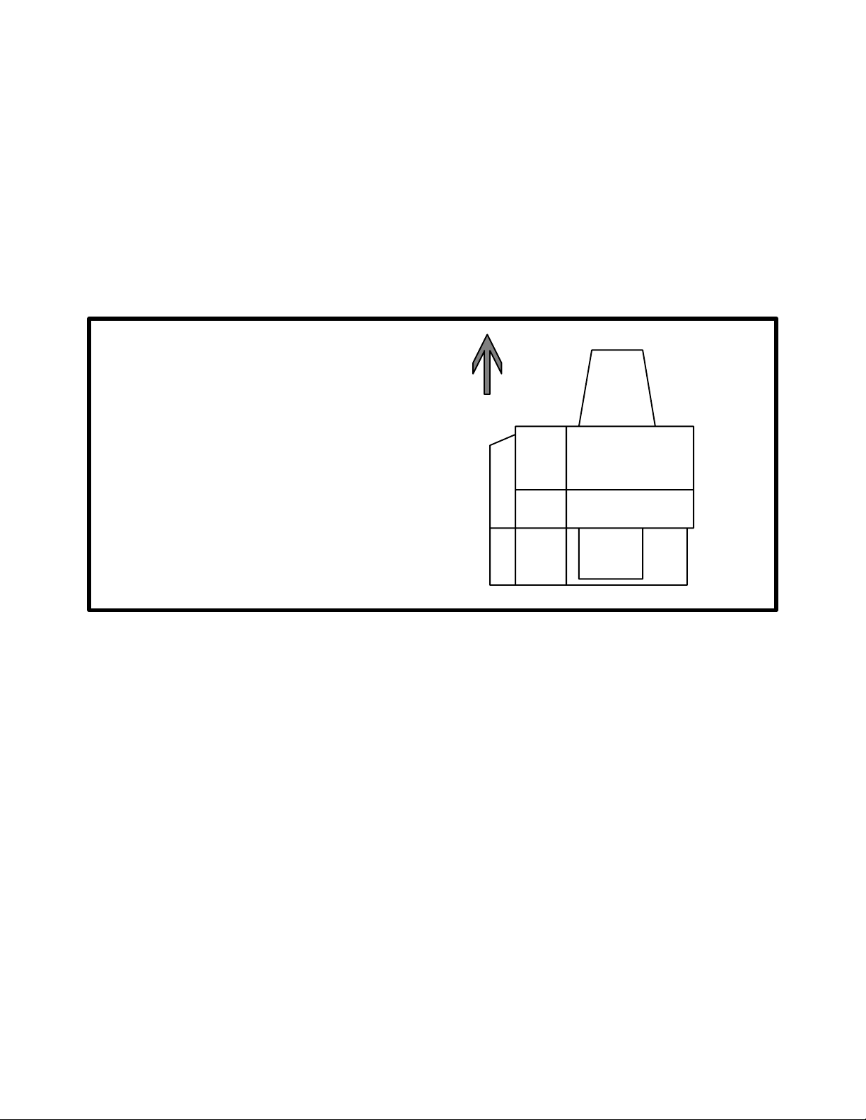
DIRECTIONS
Right and left sides of the
FRONT
paver are determined by
facing the direction the
machine travels when
TRAVEL DIRECTION
pouring concrete.
RIGHTLEFT
REAR
FIGURE 1
WARRANTY
A warranty is provided as part of MBW's support for customers who operate and
maintain their equipment as described in this manual. The warranty is stated in this
manual on page 8.
IDENTIFICATION
This manual applies to different variations of the MBW Curb and Gutter Slipform
Paver. To ensure prompt efficient service when ordering parts or requesting repairs
from authorized MBW dealers, record the serial numbers in the spaces provided.
REMEMBER - You own the very best. If repairs are needed use only MBW Inc.
parts purchased from Authorized MBW Inc. Distributors.
4
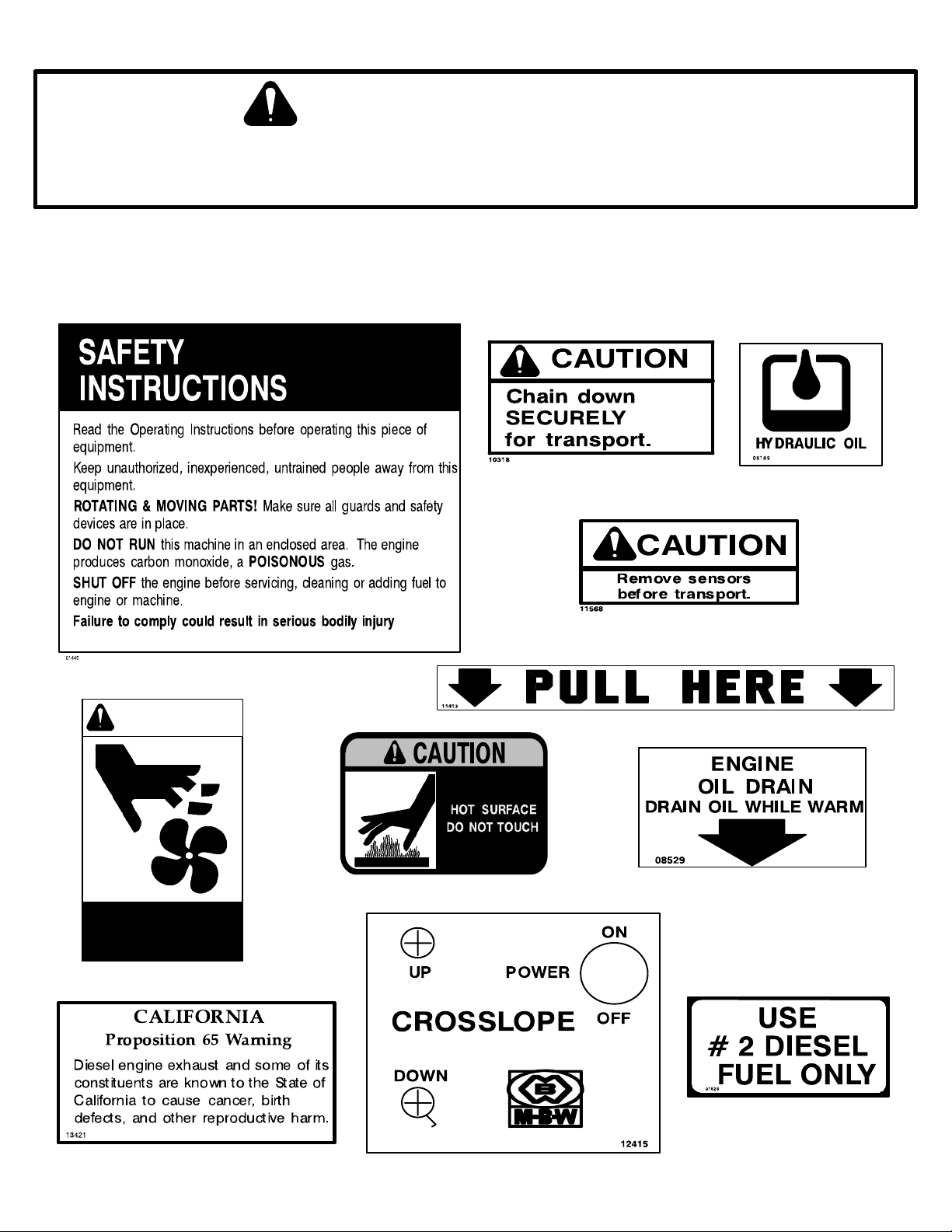
SAFETY NOTICE & DECALS
IMPORTANT NOTICE
The SAFETY ALERT SYMBOL" is used to call attention to items or operations that may be
dangerous to machine operators or others working with this equipment. The symbol can be
found throughout this manual and on the unit itself. Please read these messages carefully.
READ SAFETY DECALS CAREFULLY
Carefully read and follow all safety decals. Keep them in good condition. If decals become damaged,
replace as required. If repainting, REPLACE ALL decals. Decal Kits are available from authorized
MBW Distributors.
#01445, UPPER CORNER OF ENGINE DOOR
WARNING
#09311, ENGINE DOOR ABOVE EXHAUST
ROTATING FAN
#10318, ENGINE DOOR
FRONT WHEEL FORK
REAR WHEEL FORK
#11568, ON ALL SENSORS
#11413, BELOW RADIATOR
#08529, ENGINE OIL PAN
FACING ENGINE DOOR
#08189, HYD. TANK
Keep hands away!
#11537, SIDE OF RADIATOR
#13421. FRONT FENDER
FUEL TANK
#01623, FUEL TANK
#12415, FRONT FENDER CROSSLOPE BOX
5
SAFETY DECAL LOCATIONS
CAREFULLY READ AND FOLLOW
ALL SAFETY WARING DECALS.
REPLACE ALL DAMAGED OR
MISSING SAFTEY DECALS.
1. Control Panel:
1. Control Panel Decal #11231. (See
page 13)
2. Vibrator Decal #11699, Right side of
control panel. (See page 14)
2. Engine Compartment:
1. Pull Here #11413, Below radiator.
2. Fan Warning #11537, right side of raĆ
diatior and top of radiator shroud.
3. Oil Drain #08529, Below radiator on
front of oil pan
3. Main Unit, Engine Access Panel.
1. Safety Operating Instructions
2. Tie Down #10318.
3. Hot #09311, Above exhaust opening
6
4. Fuel-Hydraulic Tank:
1. #2 Diesel Fuel #10318, Right cap.
2, Hydraulic oil #08189, Left cap.
5. Side Drive Unit
1. Tie Down #10318, Near tire.
2. Sensor #11568, Near each sensor
bracket.
6. Hopper Unit, left side:
1. Safety instructions #01445
2. Tie Down #10318.
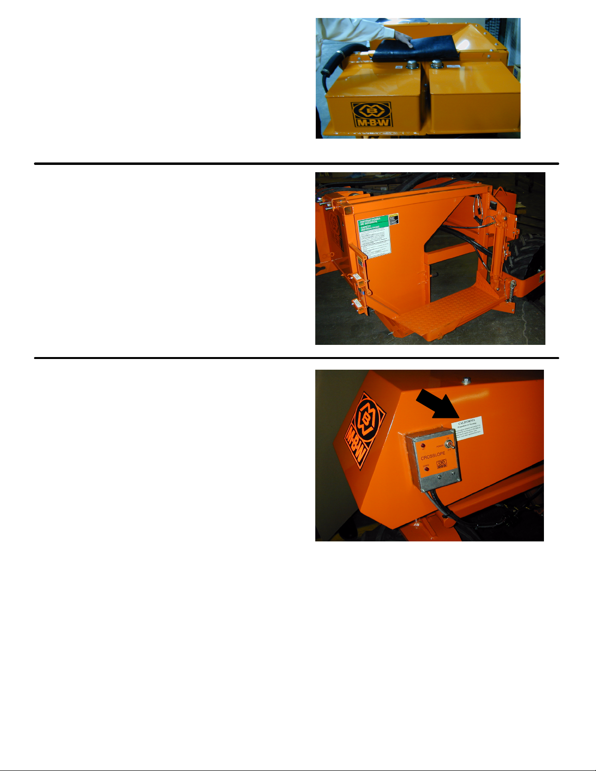
7. Front Fender:
1. Emission warning #13421.
2. California warning #12415.
7

WARRANTY
WARRANTY
THIS IS YOUR WARRANTY - PLEASE READ AND SAVE
1. MBW Inc., Slinger Wisconsin, warrants each new machine against defects in material and workmanship
under normal use and service for a period of six (6) months. This warranty commences the first day the
machine is sold, assigned to a rental fleet, or otherwise put to first use.
2. The obligation under this warranty is limited to the replacement or repair of parts and/or machine at MBW
Inc. factory branches or at authorized MBW Inc. Distributors.
3. Machines altered or modified without MBW Inc. written consent voids this warranty. Misuse, negligence,
accidents or the operation of machines in any way other than recommended by MBW Inc. will void this
warranty. This warranty shall not apply to machines repaired by other than MBW Inc. factory branches or
authorized MBW Inc. Distributors.
4. This warranty includes labor on all MBW Inc. products. Labor must be performed at an authorized MBW
Inc. Distributor.
5. The cost of transportation and other expenses connected therewith are not covered by this warranty.
6. Written authorization for the return of merchandise under warranty must be obtained from MBW Inc.,
Slinger, Wisconsin. In England: MBW (UK) LIMITED, Bradley Fold Trading Estate Unit 6, Radcliffe Moor
Road, Bolton BL2 6RT.
7. MBW Inc. reserves the right to inspect and render final decision on each warranty case.
8. MBW Inc. reserves the right to improve or make product changes without incurring any obligation to
update, refit, or install the same on machines previously sold.
9. MBW Inc. is not responsible for any liability or damage or injury directly or indirectly from design, material or
operation of its products.
10. Warranty card must be returned to MBW Inc., P.O. Box 440, Slinger, Wisconsin 53086-0440, within 10 days
after purchase, assignment to a rental fleet, or first use. In England: MBW (UK) LIMITED, Bradley Fold
Trading Estate Unit 6, Radcliffe Moor Road, Bolton BL2 6RT. Failure to return warranty card as specified
renders the warranty null and void.
11. Requests for warranty must be submitted in writing within 30 days after machine failure to MBW Inc., P.O.
Box 440, Slinger, Wisconsin 53086-0440. In England: MBW (UK) LIMITED, Bradley Fold Trading Estate
Unit 6, Radcliffe Moor Road, Bolton BL2 6RT.
12. THE FOREGOING WARRANTY IS EXPRESSLY IN LIEU OF ALL OTHER WARRANTIES, EXPRESSED OR
IMPLIED, INCLUDING THE WARRANTIES OF MERCHANTABILITY AND FITNESS FOR USE, AND OF ALL
OTHER OBLIGATION OR LIABILITIES ON OUR PART, AND WE NEITHER ASSUME NOR AUTHORIZE ANY
OTHER PERSON TO ASSUME FOR US ANY OTHER LIABILITY OR WARRANTY IN CONNECTION WITH
THE SALE OR SERVICE OF ANY OF OUR PRODUCTS. LIKEWISE, THIS WARRANTY SHALL NOT APPLY
WITH RESPECT TO ENGINES, MOTORS AND OTHER COMPONENT PARTS PRODUCED BY OTHER
MANUFACTURERS AND USED ON MBW PRODUCTS, BUT SUCH ITEMS SHALL HAVE SUCH
WARRANTIES AS MAY BE PROVIDED BY THE MANUFACTURER THEREOF.
MBW INC.
250 HARTFORD ROAD P.O. BOX 440
SLINGER, WI 53086-0440
PHONE: (262) 644-5234 FAX (262) 644-5169
MBW CORPORATE INTERNET ADDRESS
E-MAIL: mbw@mbw.com WEB SITE: www.mbw.com
IN ENGLAND:
MBW (UK) LIMITED
Bradley Fold Trading Estate Unit 6
Radcliffe Moor Road
Bolton BL2 6RT
Phone: 01204 387784 FAX: 01204 387797
8
MBW WAREHOUSE LOCATIONS
MBW (UK) LIMITED
Units 2&3 Cochrane Street
Bolton
BL3 6BN
Phone: 01204 387784
Fax: 01204 387797
2.
2
is at your service
MBW Inc. has established a network of reputable Distributors with trained mechanics and full facilities
for maintenance and rebuilding, and to carry an adequate parts stock in all areas of the country. Their
sales engineers are available for professional consultation. If you cannot locate an MBW Inc. Distributor
in your area, contact one of our Sales Branches or MBW Inc. The locations and phone numbers of the
Sales Branches are listed below.
Remember - you own the best. If repairs are needed use only MBW Inc. parts purchased from
Authorized MBW Inc. Distributors.
Sales Branches:
1. MBW Inc.
250 Hartford Rd.
P.O. Box 440
Slinger, WI 53086Ć0440
Phone: (262) 644Ć5234
FAX: (262) 644-5169
E-MAIL ON THE WORLD WIDE WEB mbw@mbw.com
WEB SITE ON THE INTERNET www.mbw.com
1
Great Britain
9

SPECIFICATIONS
MACHINE SPECIFICATIONS
MAIN UNIT with 12" HOPPER with 24" HOPPER
WEIGHT 2450 lbs. (1111 kg) 2725 lbs. (1236 kg) 3395 (lbs. (1540 kg)
LENGTH 112 in (284 cm) 112 in (284 cm) 112 in (284 cm)
WIDTH 45 in (114 cm) 63 in (160 cm) 89 in (226 cm)
HEIGHT (in pouring position) 42 in (107 cm) 42 in (107 cm) 42 in (107 cm)
HYDRAULIC RESERVOIR 12 gal (45.4 ltr) 12 gal (45.4 ltr) 12 gal (45.4 ltr)
FUEL CAPACITY 12 gal (45.4 ltr) 12 gal (45.4 ltr) 12 gal (45.4 ltr)
NOISE LEVEL* 91dBA
*Reading taken at operators ear, engine rpm - 3300.
ENGINE SPECIFICATIONS
TYPE B&S DIAHATSU
POWER RATING @ 3600 26.5 (19.8)
FUEL TYPE #2 Diesel
10
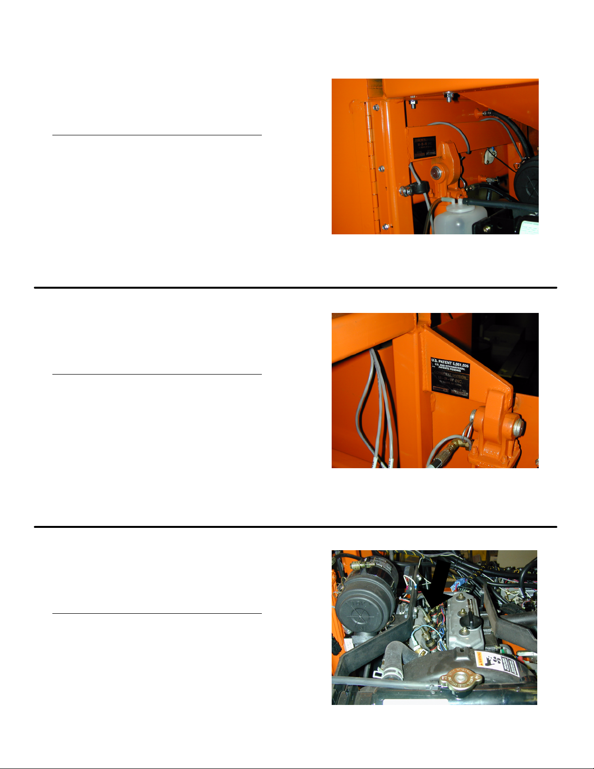
SERIAL NUMBERS
MAIN UNIT SERIAL NUMBER
Inside engine compartment towards left
while facing the engine radiator.
450-
SIDE UNIT UNIT SERIAL NUMBER
On front face of side unit height cylinder
top support.
450-
ENGINE SERIAL NUMBER
On engine block boss underneath air inĆ
take manifold.
-
11

SAFETY ALERT SYMBOL
IMPORTANT NOTICE
This is the industry's SAFETY ALERT SYMBOL". This symbol is used to call
your attention to items or operations that could be dangerous to you or other
persons using this equipment. Please read these messages carefully. It is
essential that you read the instructions and safety regulations before you
attempt to assemble or operate this machine.
CAREFULLY READ AND FOLLOW ALL SAFETY SIGNS. KEEP THEM IN GOOD
CONDITION. REPLACE ANY MISSING OR DAMAGED SAFETY SIGNS.
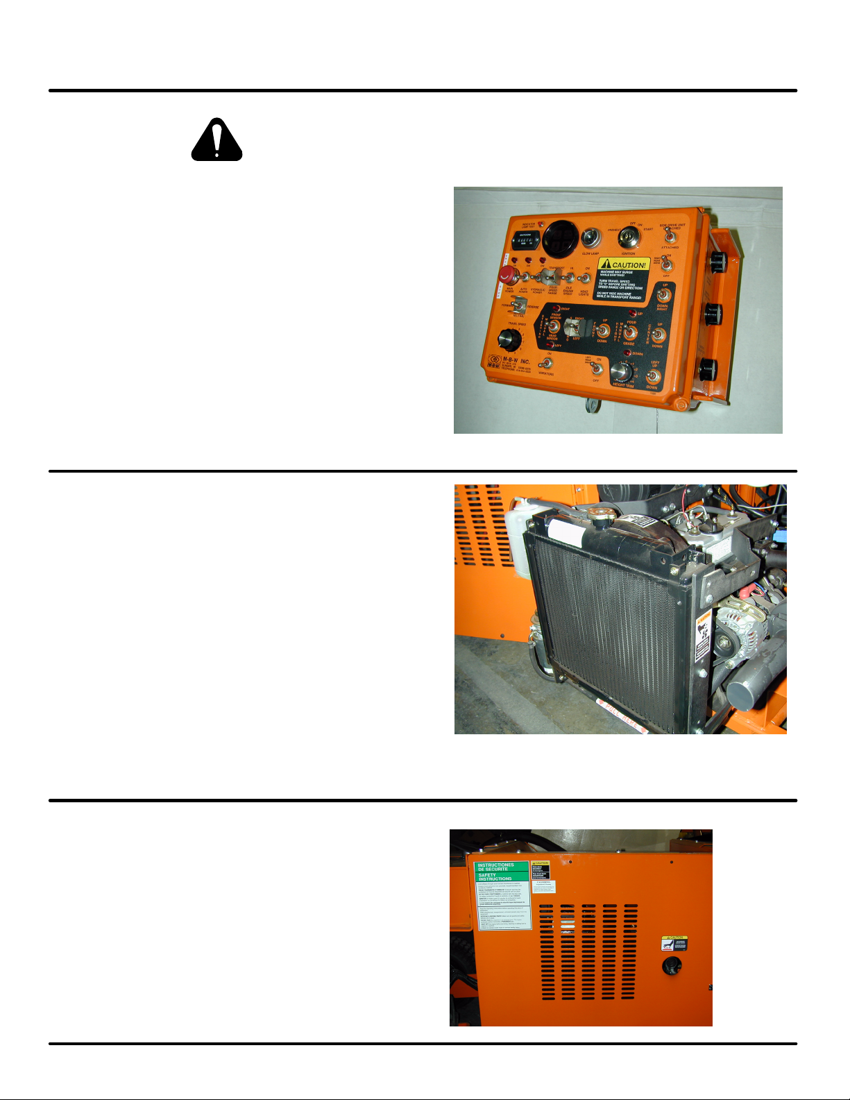
CONTROL PANEL DESCRIPTION
Read and understand the function of each control panel item
listed below before operating this machine.
1. INDICATOR LAMP TEST: Push button for testing indicator lamp cluster.
2. HOUR METER: Counts elapsed hours of machine operation.
3. INDICATOR LAMP CLUSTER: Houses low fuel and engine warning lamps.
4. GLOW LAMP: Glow plug indicator lamp.
5. IGNITION SWITCH: Engine ignition switch.
6. SIDE DRIVE UNIT: Switches Auto Height control from main unit center wheel to Side
Drive Unit wheel.
7. RIGHT REAR DRIVE: Controls power to right rear drive wheel.
8. MAIN POWER AND EMERGENCY STOP: Controls power to all non-engine related
functions.
9. AUTO POWER: Controls power to on-board computer system.
10. HYDRAULIC POWER: Controls power to all hydraulic functions.
11. SPEED RANGE: Increases travel speed for quick transport.
12. ENGINE SPEED: Preset throttle operating position.
13. HEAD LIGHTS: Work light switch.
14. FORWARD-NEUTRAL-REVERSE: Controls travel direction.
15. TRAVEL SPEED: Controls travel speed. 0"= stop, 9"= maximum.
16. STEERING: FRONT SENSOR-MANUAL-REAR SENSOR: Activates automatic steering
computer module and selects steering sensor.
17. STEERING: Controls front wheel steering.
18. FRONT: Controls front wheel height adjustment.
19. HEIGHT: POUR-MANUAL-GRADE: Activates automatic height control computer
module and selects height sensor. Controls left most height cylinder.
20. RIGHT: Controls right wheel height adjustment.
21. CENTER: Controls center wheel height adjustment.
22. LEFT: Controls left (side drive unit) wheel height adjustment.
23. HEIGHT TRIM: Sets automatic height control zero reference point.
24. VIBRATORS: Controls power to vibrator potentiometers.
25. LEFT REAR DRIVE: Controls power to left (side drive) wheel.
26. VIBRATOR 1 POT: Controls main unit vibrator speed. (Right side of panel)
27. VIBRATOR 2 POT: Controls hopper unit vibrator speed. (Right side of panel)
28. VIBRATOR 3 POT: Controls hopper unit vibrator speed. (Right side of panel)
12
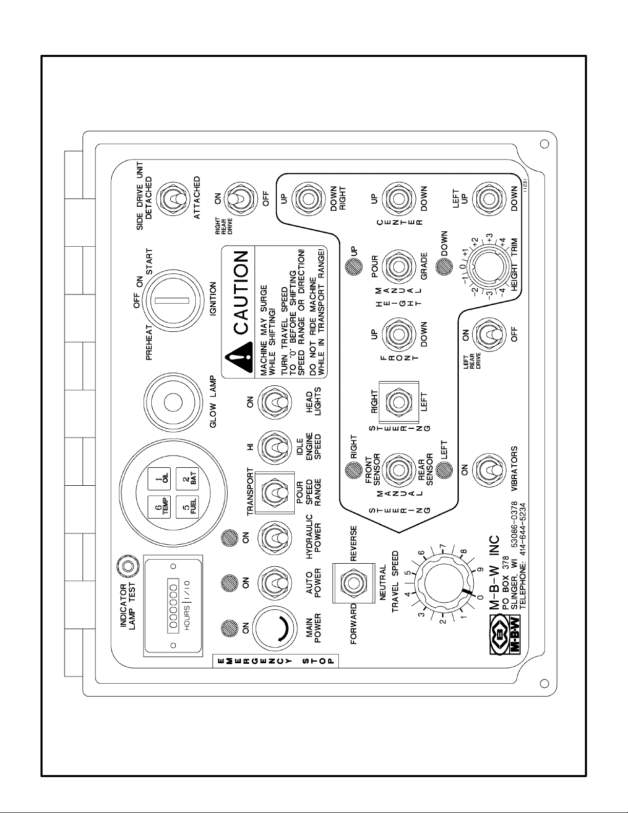
CONTROL PANEL
13

VIBRATOR CONTROLS
14

OPERATING INSTRUCTIONS
BEFORE OPERATION, READ THESE INSTRUCTIONS
AND SEE THE PERIODIC MAINTENANCE" SECTION.
MAKE SURE HANDS, FEET, AND CLOTHING ARE AT A SAFE DISTANCE
FROM ANY MOVEABLE PARTS BEFORE STARTING. REVIEW RELATED
SAFETY PRECAUTIONS LISTED ON PAGE 3.
MAKE SURE ALL CONTROLS ARE IN THE NEUTRAL OR OFF POSITION.
WARNING - DANGEROUS FUELS! Use extreme caution when storing,
handling and using fuels - they are highly volatile and explosive in vapor
state. Do not add fuel while engine is running. Stop engine and allow a coolĆ
ing period to prevent spilled fuel from igniting on contact with hot engine parts.
DO NOT SMOKE!
OIL LEVEL Ć Check the oil level in the engine. See Lubrication" under the
respective engine's OWNERS MANUAL".
AIR CLEANER Ć Check to make sure the element is clean and in good condiĆ
tion and properly installed.
FUEL FILTER Ć Clean the sediment bowl as required.
ENGINE COOLANT Ć Check the level by removing the pressure cap at the top
of the radiator. The coolant level should be 1/2" below the base of the filler
neck. Be sure to tighten the radiator pressure cap. The radiator is filled with an
antifreeze solution. If the coolant level becomes low due to evaporation, add
water only. If the coolant level becomes low due to leakage or overflow, add a
mixture of antifreeze and water in the ratio specified by the antifreeze manufacĆ
turer.
BATTERY - Ensure that the electrolyte level is correct. The battery capacity
diminishes as the temperature decreases. Monitor charging system performĆ
ance to maintain battery capacity. During cold weather storage, remove the
battery from the machine.
FUEL SUPPLY Ć The engine on the MBW Curb and Gutter Slipform Paver reĆ
quires diesel light oil #2 Diesel.
HYDRAULIC OIL Ć Check the hydraulic oil reservoir. The oil level should be
between 2-1/2" to 3" from bottom of dip stick. Fill with Dexron II ATF as reĆ
quired.
15
 Loading...