

MBW Blitzscreed User Manual
OPERATOR’S SAFETY
AND SERVICE MANUAL
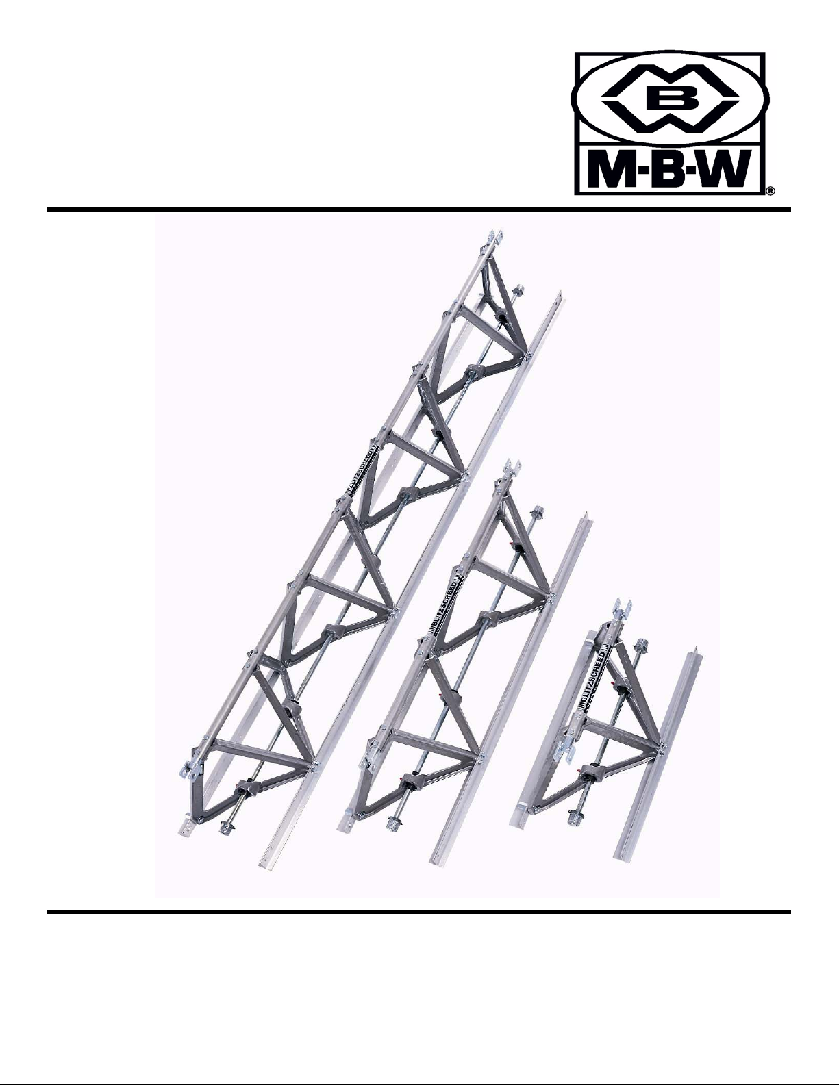
BLITZSCREED
CONCRETE SCREEDS
MBW, Inc.
250 Hartford Rd • PO Box 440
Slinger, WI 53086-0440
Phone: (262) 644-5234
Fax: (262) 644-5169
Email: mbw@mbw.com
Website: www.mbw.com
MBW (UK) Ltd.
Units 2 & 3 Cochrane Street
Bolton BL3 6BN, England
Phone: 01204 387784
Fax: 01204 387797
L2335 / 08.06.H
©MBW, Inc. 2006
Printed in the USA

TABLE OF CONTENTS
SAFETY PRECAUTIONS 1. . . . . . . . . . . . . . . . . . . . . . . . . . . . . . . . . . . . . . . . .
INTRODUCTION 2. . . . . . . . . . . . . . . . . . . . . . . . . . . . . . . . . . . . . . . . . . . . . . . . .
SAFETY NOTICE & DECALS 3. . . . . . . . . . . . . . . . . . . . . . . . . . . . . . . . . . . . .
SAFETY DECAL LOCATIONS 5. . . . . . . . . . . . . . . . . . . . . . . . . . . . . . . . . . . . .
WARRANTY 7. . . . . . . . . . . . . . . . . . . . . . . . . . . . . . . . . . . . . . . . . . . . . . . . . . . . .
MBW WAREHOUSE LOCATIONS 8. . . . . . . . . . . . . . . . . . . . . . . . . . . . . . . . .
BLITZSCREED SPECIFICATIONS 9. . . . . . . . . . . . . . . . . . . . . . . . . . . . . . . . .
SERIAL NUMBER LOCATION 10. . . . . . . . . . . . . . . . . . . . . . . . . . . . . . . . . . . . .
PARTS ORDERING PROCEDURE 10. . . . . . . . . . . . . . . . . . . . . . . . . . . . . . . . .
SECTION ASSEMBLY 11. . . . . . . . . . . . . . . . . . . . . . . . . . . . . . . . . . . . . . . . . . . .
ENGINE ASSEMBLY 14. . . . . . . . . . . . . . . . . . . . . . . . . . . . . . . . . . . . . . . . . . . . .
END FRAME ASSEMBLY 16. . . . . . . . . . . . . . . . . . . . . . . . . . . . . . . . . . . . . . . . .
AIR DRIVE ASSEMBLY 16. . . . . . . . . . . . . . . . . . . . . . . . . . . . . . . . . . . . . . . . . . .
HYDRAULIC DRIVE ASSEMBLY 17. . . . . . . . . . . . . . . . . . . . . . . . . . . . . . . . . .
OPERATING INSTRUCTIONS 18. . . . . . . . . . . . . . . . . . . . . . . . . . . . . . . . . . . . .
MAINTENANCE & SERVICE, SCREED 21. . . . . . . . . . . . . . . . . . . . . . . . . . . .
A-FRAME REPLACEMENT 21. . . . . . . . . . . . . . . . . . . . . . . . . . . . . . . . . . .
BEARING REPLACEMENT 22. . . . . . . . . . . . . . . . . . . . . . . . . . . . . . . . . . . .
DRIVE BELT REPLACEMENT 22. . . . . . . . . . . . . . . . . . . . . . . . . . . . . . . . . .
GREASING BEARINGS 22. . . . . . . . . . . . . . . . . . . . . . . . . . . . . . . . . . . . . . .
LONG STORAGE 23. . . . . . . . . . . . . . . . . . . . . . . . . . . . . . . . . . . . . . . . . . . . .
TORQUE CHART 23. . . . . . . . . . . . . . . . . . . . . . . . . . . . . . . . . . . . . . . . . . . . .
BEARING LOCATIONS 24. . . . . . . . . . . . . . . . . . . . . . . . . . . . . . . . . . . . . . .
AIR EXCITER & GROMMET LOCATIONS 25. . . . . . . . . . . . . . . . . . . . . . .
MODEL MVS2 27. . . . . . . . . . . . . . . . . . . . . . . . . . . . . . . . . . . . . . . . . . . . . . . . . . .
MODEL MVS4 29. . . . . . . . . . . . . . . . . . . . . . . . . . . . . . . . . . . . . . . . . . . . . . . . . . .
MODEL MVS8 31. . . . . . . . . . . . . . . . . . . . . . . . . . . . . . . . . . . . . . . . . . . . . . . . . . .
ENGINE KITS 33. . . . . . . . . . . . . . . . . . . . . . . . . . . . . . . . . . . . . . . . . . . . . . . . . . .
5.5 HP HONDA ENGINE KIT 34. . . . . . . . . . . . . . . . . . . . . . . . . . . . . . . . . . .
5.0 HP BRIGGS & STRATTON ENGINE KIT 35. . . . . . . . . . . . . . . . . . . . .
8.0 HP HONDA ENGINE KIT 36. . . . . . . . . . . . . . . . . . . . . . . . . . . . . . . . . . .
MODEL AVS2 37. . . . . . . . . . . . . . . . . . . . . . . . . . . . . . . . . . . . . . . . . . . . . . . . . . .
MODEL AVS4 39. . . . . . . . . . . . . . . . . . . . . . . . . . . . . . . . . . . . . . . . . . . . . . . . . . .
MODEL AVS8 41. . . . . . . . . . . . . . . . . . . . . . . . . . . . . . . . . . . . . . . . . . . . . . . . . . .
AIR REGULATOR KIT 43. . . . . . . . . . . . . . . . . . . . . . . . . . . . . . . . . . . . . . . . . . . .
HAND WINCH KIT 45. . . . . . . . . . . . . . . . . . . . . . . . . . . . . . . . . . . . . . . . . . . . . . .
HYDRAULIC WINCH KIT 47. . . . . . . . . . . . . . . . . . . . . . . . . . . . . . . . . . . . . . . . .
WINCH ASSEMBLY 53. . . . . . . . . . . . . . . . . . . . . . . . . . . . . . . . . . . . . . . . . . . . . .
i

SAFETY PRECAUTIONS
READ AND STUDY THE FOLLOWING SAFETY INFORMATION BEFORE ATTEMPTING TO OPERĆ
ATE THIS EQUIPMENT. IN ADDITION, ENSURE THAT EVERY INDIVIDUAL WHO OPERATES OR
WORKS WITH THIS EQUIPMENT IS FAMILIAR WITH THESE SAFETY PRECAUTIONS.
W ARNING – LETHAL EXHAUST GAS!
An internal combustion engine discharges carbon monoxide, a poisonous, odorless invisible gas.
Death or serious illness may result if inhaled. Operate only in an area with good ventilation, NEVER IN
A CONFINED AREA!
W ARNING – DANGEROUS FUELS!
Use extreme caution when storing, handling and using fuels - they are highly volatile and explosive in
vapor state. Do not add fuel while engine is running. Stop and cool the engine before adding fuel. DO
NOT SMOKE!
SAFETY GUARDS
It is the owner's responsibility to ensure ALL GUARDS AND SHIELDS are in place and in working
order.
IGNITION SYSTEMS
Breakerless, magneto and battery ignition systems CAN CAUSE SEVERE ELECTRICAL SHOCKS.
Avoid contacting these units or their wiring.
SAFE DRESS
DO NOT WEAR loose clothing, rings, wristwatches, etc., near machinery.
NOISE PROTECTION
Wear O.S.H.A. specified hearing protection devices.
FOOT PROTECTION
Wear O.S.H.A. specified steel tip safety shoes.
HEAD PROTECTION
Wear O.S.H.A. specified safety helmets.
EYE PROTECTION
Wear O.S.H.A. specified eye shields, safety glasses, and sweat bands.
OPERATOR
Keep children and bystanders off and away from the equipment.
REFERENCES
For details on safety rules and regulations in the United States, contact your local Occupational Safety
and Health Administration (O.S.H.A.) office. Equipment operated in other countries must be operated
and serviced in accordance and compliance with any and all safety requirements of that country.The
publication of these safety precautions is done for your information. MBW Inc. does not by the publiĆ
cation of these precautions, imply or in any way represent that these are the sum of all dangers preĆ
sent near MBW equipment. If you are operating MBW Inc. equipment, it is your responsibility to insure
that such operation is in full accordance with all applicable safety requirements and codes. All reĆ
quirements of the United States Federal Occupational Safety and Healthy Administration Act must be
met when operated in areas that are under the jurisdiction of that United States Department.
1a
INTRODUCTION
MBW Inc. SCREED is intended for use in many applications. It offers the highest level of finishing consistency
available today. Precision machining of all components, combined with all bolted construction, are the key
factors for ease and speed of assembly and for true alignment job after job.
MBW Inc's exclusive 45 degree AĆframe cast aluminum design assures that all sections are exactly the same
and totally interchangeable. They come in 8'4", 4'4" and 2'4" lengths, so you can mix and match the length
you need up to 65 ft (20 m) for gas models and 65 ft (20 m) for air models.
The gasoline engine driven SCREED gives you a maximum eccentric speed of 2800 rpm, and permits idling of
the SCREED without stopping the engine. The air driven version gives you cycle vibration ranging from 5000
to 8000 VPM at 40 psi to 60 psi using about 4 CFM per vibrator.
The gasoline engine driven SCREED has winch kits available. The hand winch kit and the hydraulic winch kit.
The air powered SCREED offers the same fine features as our mechanical unit. It comes with optional handles
and an air system that includes filter, regulator and lubricator. It features an air line that is protected from damĆ
age by running inside the length of the AĆframe structure, and has flexible hose couplings between the air supĆ
ply tubes.
MBW Inc. has invested a great deal of time and effort in developing its SCREED. The equipment you have
purchased is built with a great deal of pride and designed to give you long life, efficient operation, durability and
dependability.
READ THIS MANUAL
The information in this manual has been written in an easy to read style. The design features makes it convenĆ
ient to operate and service your MBW Inc. SCREED through the use of this manual.
Read this manual carefully to learn how to operate and service your MBW Inc. SCREED correctly. Failure to do
so could result in personal injury or equipment damage.
Major points of safe operation are detailed on the SAFETY PRECAUTIONS page of this manual. The SAFETY
PRECAUTIONS page is located on page 1.
This manual should be considered a permanent part of your SCREED and should remain with the SCREED.
MEASUREMENTS
U.S. Units of measure and their metric equivalents are used in this manual.
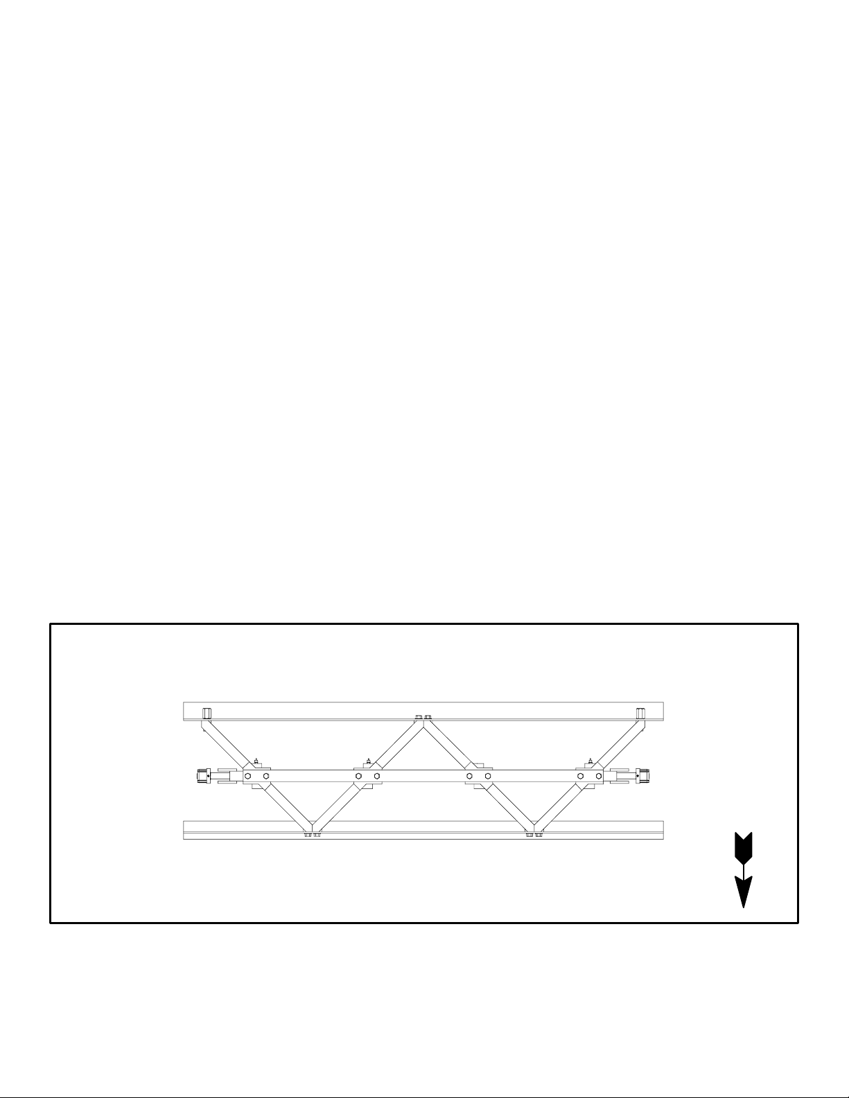
DIRECTIONS
Right and left sides of the screed are determined by facing the front (strikeoff) edging (T"
shaped edging). See Figure 1.
BACK (FLOAT)
LEFT
RIGHT
DIRECTION
FRONT (STRIKEOFF)
OF TRAVEL
FIGURE 1
WARRANTY
Warranty is provided as part of MBW Inc's support for customers who operate and maintain their
equipment as described in this manual. The warranty is stated on page 7.
MBW, Inc. reserves the right to make changes or improvements in the design or construction of any
part without incurring the obligation to install such changes on any piece of equipment previously
delivered.
2
SAFETY NOTICE & DECALS
IMPORTANT NOTICE
The SAFETY ALERT SYMBOL" is used to call attention to items or operations that may be
dangerous to machine operators or others working with this equipment. The symbol can be
found throughout this manual and on the unit itself. Please read these messages carefully.
READ SAFETY DECALS CAREFULLY
Carefully read and follow all safety decals. Keep them in good condition. If decals become
damaged, replace as required. Decal Kits are available from authorized MBW Distributors.
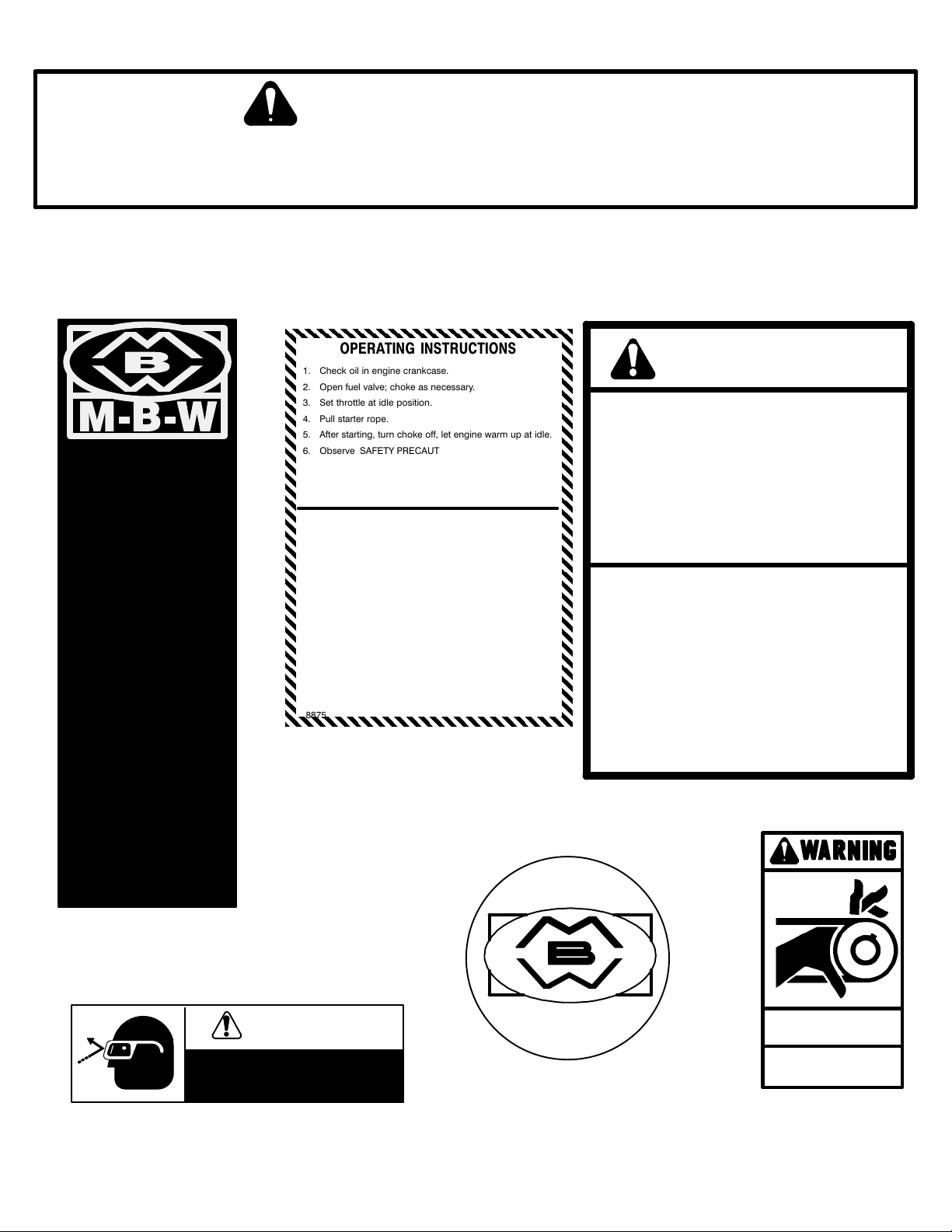
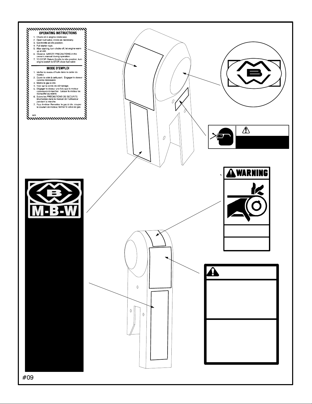
-Decals shown below are located on the engine belt guard.
OPERATING INSTRUCTIONS
CAUTION
L
I
T
Z
S
C
R
1. Check oil in engine crankcase.
2. Open fuel valve; choke as necessary.
3. Set throttle at idle position.
4. Pull starter rope.
5. After starting, turn choke off, let engine warm up at idle.
6. Observe SAFETY PRECAUTIONS in the owner's
manual during operation.
7. TO STOP: Return throttle to idle position, turn engine
switch to STOP, close fuel valve
MODE D'EMPLOI
1. Vérifier le niveau d'huile dans le carter du moteur.
2. Ouvrir le volet á carburant. Engager le doseur
comme nécessaire.
3. Mettre le gaz á idle.
4. Tirer sur la corde de démarrage.
5. Dégager le doseur une fois que le moteur commence
á marcher. Laisser le moteur se réchauffer au ralenti.
6. Suivre les PRECAUTIONS DE SECURITE énumerées
dans le manuel de I'utilisateur pendant la marche.
7. Pour Arrêtter: Remettre le gaz á idle, couper le
courant de moteur, fermer le valve de ga
8875
s.
#08875, Belt Guard
Read the operating instructions before operating this piece of
equipment.
Keep unauthorized, inexperienced, untrained people away from
this equipment.
CHECK saftey switch frequently for proper operation.
ROTATING & MOVING PARTS! Make sure all guards and safety
devices are in place.
DO NOT RUN this machine in an enclosed area. The engine
produces carbon monoxide, a POISONOUS gas.
SHUT OFF the engine before servicing , cleaning or adding fuel.
Failure to comply could result in serious bodly injury.
Lire le Mode d'Emploi avant de faire fonctionner le matériel
Eloigner toute personne non formée, non autorisée et inexpérimentée
du matériel.
VERIFIER fréquemment I'interrupteur de sécurité pour un bon
fonctionnement.
PIECES TOURNANTES ET MOBILES! S'assurer que tous les
protecteurs et les dispositifs de sécurité sont en place.
NE PAS FAIRE FONCTIONNER le matériel dans les lieux clos. Le
moteur produit de l'oxyde de carbone, un gaz TOXIQUE.
ARRETER le moteur avant d'entretenir ou de nettoyer, et avant d'y
ajouter de l'essence.
L'inobservation des consignes de sécurité risque de provoquer de
graves blessures corporelles.
1447
E
#01447, Belt Guard
E
ą
D
09095
#09095, Belt Guard
15459
#15459, Belt Guard
CAUTION
WEAR EYE PROTECTION
WHEN
OPERATING EQUIPMENT
MĆBĆW
INC.
1060E
#01060E, Belt Guard
3
PIECES ROTATIVES
Ne pas toucher!
ROTATING PARTS
Keep hands away!
11640
#11640, Belt Guard
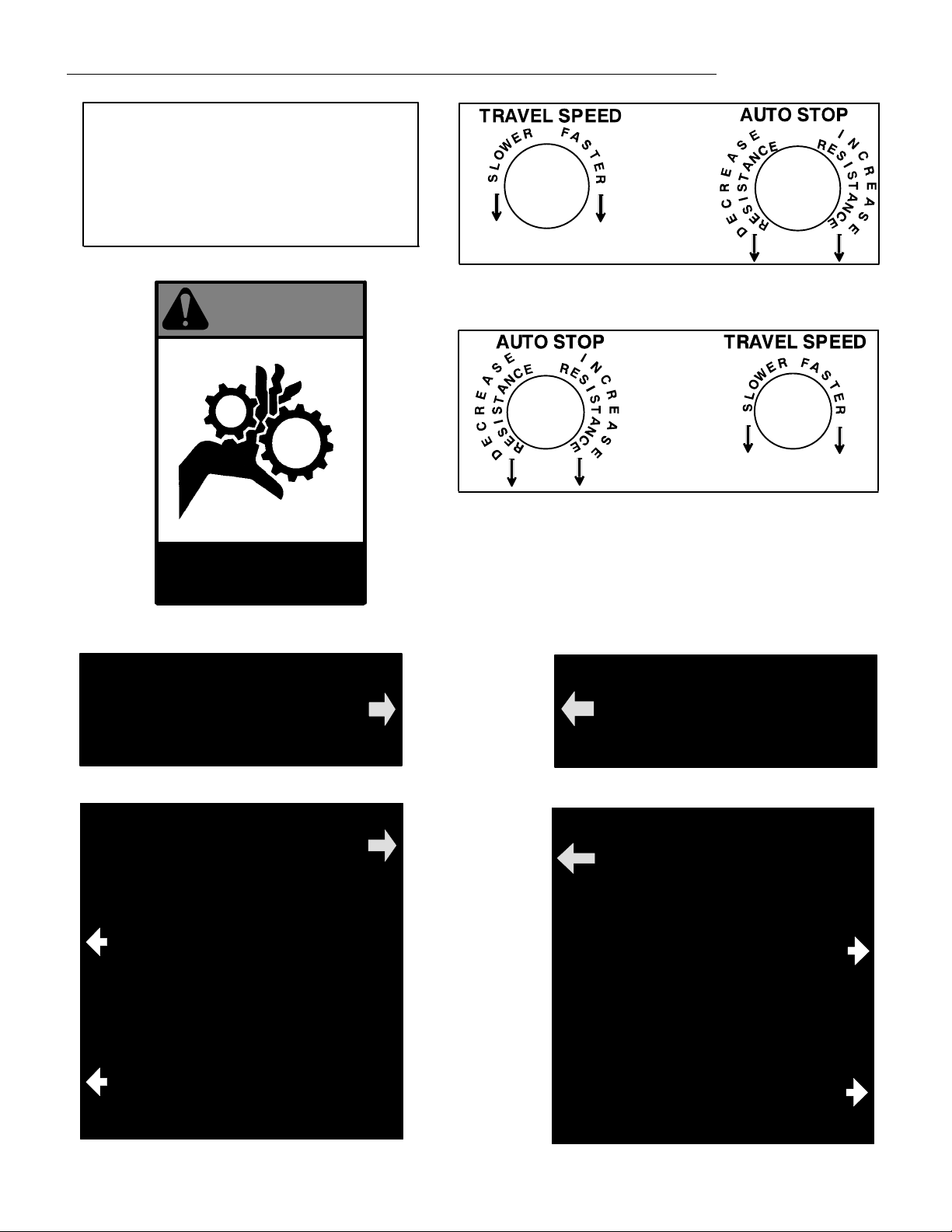
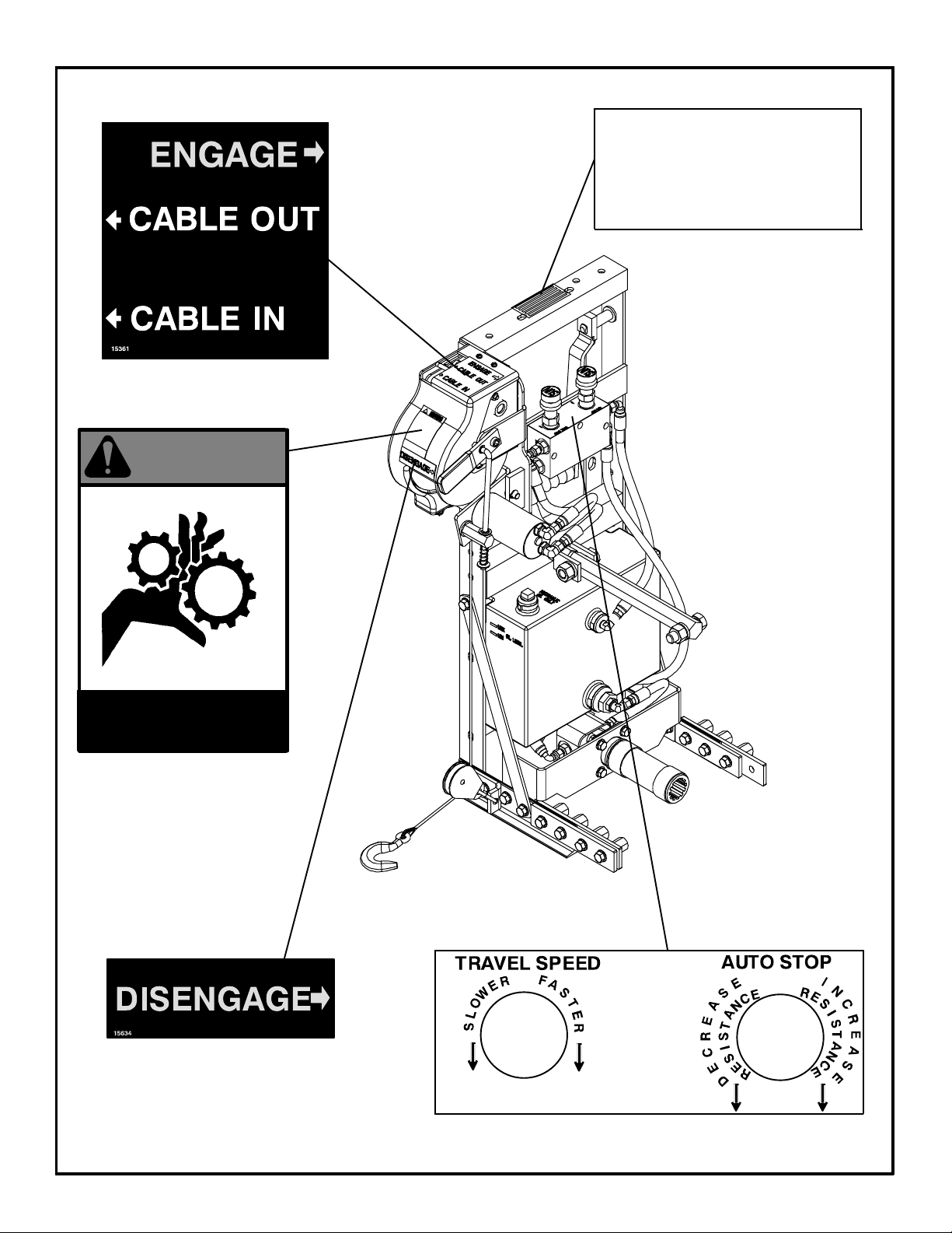
Decals shown below are located only on the hydraulic winches.
AUTO STOP MUST BE ADJUSTED EACH
TIME SCREED LENGTH OR OPERATING
CONDITIONS CHANGE. SET TRAVEL
SPEED, THEN INCREASE OR DECREASE
AUTO STOP RESISTANCE TO A POINT
SLIGHTLY HIGHER THAN REQUIRED TO
MAINTAIN DESIRED TRAVEL SPEED.
#15399 (TOP OF SUPPORT FRAME)
15399
15400
#15400 (TOP OF VALVE BLOCK, RIGHT)
WARNING
15401
#15401 (TOP OF VALVE BLOCK, LEFT)
ROTATING PARTS
Keep hands away!
15518
#15518 (WINCH COVER)
DISENGAGE
15634
#15634 (WINCH COVER, LEFT)
ENGAGE
CABLE OUT
DISENGAGE
15398
#15398 (WINCH COVER, RIGHT)
ENGAGE
CABLE OUT
CABLE IN
15361
#15631 (WINCH COVER, LEFT)
CABLE IN
15632
#15632 (WINCH COVER, RIGHT)
4
SAFETY DECAL LOCATIONS
#08875, On Belt Guard
MĆBĆW
INC.
1060E
#01060E, On Belt Guard
CAUTION
WEAR EYE PROTECTION
WHEN
OPERATING EQUIPMENT
15459
#15459, On Belt Guard
L
I
T
Z
S
C
R
E
E
ą
D
09095
#09095, On Belt Guard
PIECES ROTATIVES
Ne pas toucher!
ROTATING PARTS
Keep hands away!
11640
#11640, On Belt Guard
CAUTION
Read the operating instructions before operating this piece of
equipment.
Keep unauthorized, inexperienced, untrained people away from
this equipment.
CHECK saftey switch frequently for proper operation.
ROTATING & MOVING PARTS! Make sure all guards and safety
devices are in place.
DO NOT RUN this machine in an enclosed area. The engine
produces carbon monoxide, a POISONOUS gas.
SHUT OFF the engine before servicing , cleaning or adding fuel.
Failure to comply could result in serious bodly injury.
Lire le Mode d'Emploi avant de faire fonctionner le matériel
Eloigner toute personne non formée, non autorisée et
inexpérimentée du matériel.
VERIFIER fréquemment I'interrupteur de sécurité pour un bon
fonctionnement.
PIECES TOURNANTES ET MOBILES! S'assurer que tous les
protecteurs et les dispositifs de sécurité sont en place.
NE PAS FAIRE FONCTIONNER le matériel dans les lieux clos.
Le moteur produit de l'oxyde de carbone, un gaz TOXIQUE.
ARRETER le moteur avant d'entretenir ou de nettoyer, et avant
d'y ajouter de l'essence.
L'inobservation des consignes de sécurité risque de
provoquer de graves blessures corporelles.
#01447, On Belt Guard
ą
1447
5
SAFETY DECAL LOCATIONS
WARNING
AUTO STOP MUST BE ADJUSTED EACH
TIME SCREED LENGTH OR OPERATING
CONDITIONS CHANGE. SET TRAVEL
SPEED, THEN INCREASE OR DECREASE
AUTO STOP RESISTANCE TO A POINT
SLIGHTLY HIGHER THAN REQUIRED TO
MAINTAIN DESIRED TRAVEL SPEED.
15399
ROTATING PARTS
Keep hands away!
15518
15400
6

WARRANTY
WARRANTY
THIS IS YOUR WARRANTY - PLEASE READ AND SAVE
1. MBW INC, Slinger Wisconsin, warrants each new machine against defects in material and workmanship
under normal use and service for a period of six (6) months. This warranty commences the first day the
machine is sold, assigned to a rental fleet, or otherwise put to first use.
2. The obligation under this warranty is limited to the replacement or repair of parts and/or machine at MBW
INC factory branches or at authorized MBW INC Distributors.
3. Machines altered or modified without MBW INC written consent voids this warranty. Misuse, negligence,
accidents or the operation of machines in any way other than recommended by MBW INC will void this
warranty. This warranty shall not apply to machines repaired by other than MBW INC factory branches or
authorized MBW INC Distributors.
4. This warranty includes labor on all MBW INC products. Labor must be performed at an authorized MBW INC
Distributor.
5. The cost of transportation and other expenses connected therewith are not covered by this warranty.
6. Written authorization for the return of merchandise under warranty must be obtained from MBW INC,
Slinger, Wisconsin. In England: MBW (UK) LIMITED, Bradley Fold Trading Estate Unit 6, Radcliffe Moor
Road, Bolton BL2 6RT.
7. MBW INC reserves the right to inspect and render final decision on each warranty case.
8. MBW INC reserves the right to improve or make product changes without incurring any obligation to
update, refit, or install the same on machines previously sold.
9. MBW INC is not responsible for any liability or damage or injury directly or indirectly from design, material or
operation of its products.
10. Warranty card must be returned to MBW INC, P.O. Box 440, Slinger, Wisconsin 53086-0440, within 10 days
after purchase, assignment to a rental fleet, or first use. In England: MBW (UK) LIMITED, Bradley Fold
Trading Estate Unit 6, Radcliffe Moor Road, Bolton BL2 6RT. Failure to return warranty card as specified
renders the warranty null and void.
11. Requests for warranty must be submitted in writing within 30 days after machine failure to MBW INC, P.O.
Box 440, Slinger, Wisconsin 53086-0440. In England: MBW (UK) LIMITED, Bradley Fold Trading Estate
Unit 6, Radcliffe Moor Road, Bolton BL2 6RT.
12. THE FOREGOING WARRANTY IS EXPRESSLY IN LIEU OF ALL OTHER WARRANTIES, EXPRESSED OR
IMPLIED, INCLUDING THE WARRANTIES OF MERCHANTABILITY AND FITNESS FOR USE, AND OF ALL
OTHER OBLIGATION OR LIABILITIES ON OUR PART, AND WE NEITHER ASSUME NOR AUTHORIZE ANY
OTHER PERSON TO ASSUME FOR US ANY OTHER LIABILITY OR WARRANTY IN CONNECTION WITH
THE SALE OR SERVICE OF ANY OF OUR PRODUCTS. LIKEWISE, THIS WARRANTY SHALL NOT APPLY
WITH RESPECT TO ENGINES, MOTORS AND OTHER COMPONENT PARTS PRODUCED BY OTHER
MANUFACTURERS AND USED ON MBW PRODUCTS, BUT SUCH ITEMS SHALL HAVE SUCH
WARRANTIES AS MAY BE PROVIDED BY THE MANUFACTURER THEREOF.
MBW INC.
250 HARTFORD ROAD P.O. BOX 440
SLINGER, WI 53086-0440
PHONE: (262) 644-5234 FAX (262) 644-5169
MBW CORPORATE INTERNET ADDRESS
E-MAIL: mbw@mbw.com WEB SITE: www.mbw.com
IN ENGLAND:
MBW (UK) LIMITED
Units 2 & 3 Cochrane Street
Bolton
BL3 6BN
Phone: 01204 387784 FAX: 01204 387797
7

MBW WAREHOUSE LOCATIONS
is at your service
MBW Inc. has established a network of reputable Distributors with trained mechanics and full facilities
for maintenance and rebuilding, and to carry an adequate parts stock in all areas of the country. Their
sales engineers are available for professional consultation. If you cannot locate an MBW Inc. Distributor
in your area, contact one of our Sales Branches or MBW Inc. The locations and phone numbers of the
Sales Branches are listed below.
Remember - you own the best. If repairs are needed use only MBW Inc. parts purchased from
Authorized MBW Inc. Distributors.
Sales Branches:
1. MBW Inc.
250 Hartford Rd.
P.O. Box 440
Slinger, WI 53086Ć0440
Phone: (262) 644Ć5234
FAX: (262) 644-5169
E-MAIL ON THE WORLD WIDE WEB mbw@mbw.com
WEB SITE ON THE INTERNET www.mbw.com
2. MBW (UK) LIMITED
Units 2 & 3 Cochrane Street
Bolton
BL3 6BN
Phone: 01204 387784
FAX: 01204 387797
1
Great Britain
2
8

BLITZSCREED SPECIFICATIONS
Mechanical
Section Length
Model Section Length
MVS8 8 ft. 4 in. (2.54 m). . . . . . . . . . . . . . . . . .
MVS4 4 ft. 4 in. (1.32 m). . . . . . . . . . . . . . . . . .
MVS2 2 ft. 4 in. (0.71 m). . . . . . . . . . . . . . . . . .
Screed Blades
Front (Strikeoff)
T" Profile Blade Standard. . . . . . . .
L" Profile Blade Optional. . . . . . . . .
Plow Blade Optional. . . . . . . . . . . . .
Tamper Blade Optional. . . . . . . . . . .
(Float)
Rear
L" Profile Blade Standard. . . . . . . . .
Truss Dimensions
Height 16in (40.7cm). . . . . . . . . . . . . . . . .
Width 15in (38.1mm). . . . . . . . . . . . . . . . . .
Weight approx. (excluding engine)
All Models 8.3 lbs./ft. (12 kg/m). . . . . . . . . . . . . .
Air Powered
Section Length
Model Section Length
AVS8 8 ft. 4 in. (2.54 m). . . . . . . . . . . . . . . . . .
AVS4 4 ft. 4 in. (1.32 m). . . . . . . . . . . . . . . . . .
AVS2 2 ft. 4 in. (0.71 m). . . . . . . . . . . . . . . . . .
Screed Blades
Front (Strikeoff)
T" Profile Blade Standard. . . . . . . .
L" Profile Blade Optional. . . . . . . . .
Plow Blade Optional. . . . . . . . . . . . .
Tamper Blade Optional. . . . . . . . . . .
(Float)
Rear
L" Profile Blade Standard. . . . . . . . .
Truss Dimensions
Height 16in (40.7cm). . . . . . . . . . . . . . . . .
Width 15in (38.1cm). . . . . . . . . . . . . . . . . .
Weight approx. (excluding regulator kit)
All Models 8.9 lbs./ft. (13.2 kg/m). . . . . . . . . . . . . .
Engines
Model Rated Power
Briggs & Stratton
Model 135232 5.0hp / 3.7kW. . . . . . . . . .
Honda
Model GX160K1QX 5.5hp / 4.1kW. . . . . .
Honda
GX240K1QA2 8.0hp / 6.0kW. . . . . . . . . . .
Vibrations per minute
All Models 5000-8000. . . . . . . . . . . . . .
Air Operating Pressure
All Models 40 - 60 psi (0.28 - 0.41 MPa). . . . . . .
Air Usage
All Models 4 cfm (0.11 m3/min.) / vibrator. . . . . . .
Engine Speed (max.)
All models 2800 RPM. . . . . . . . . . . . . .
Eccentric Shaft Speed (max.)
All models 2800 RPM. . . . . . . . . . . . . .
Centrifugal Force / Unit Length
All models 15.0 lbs. / ft ( 220 N/m). . . . . . . . . . . . . .
@ 2800 RPM
Width 9.75 in (24.8cm). . . . . . . . . . . .
Hydraulic Winch
(For Mechanical Screeds)
Noise Level 89 dba. . . . . . . . . .
Weight 82 lbs./side (37 kg/side). . . . . . . . . . . . . .
Length 10 in (25.4cm). . . . . . . . . . . . . .
Height 34 in (86.4cm). . . . . . . . . . . . .
Oil Capacity 1.7 gal (6.4 l). . . . . . . .
Speed ........... 0-16.7 ft/min (0-5.1 m/min)
9

SERIAL NUMBER LOCATION
SCREED AND HYDRAULIC WINCH SERIAL NUMBERS
The serial number for each screed section is located on the side of the left most A-Frame.
The serial number is also stamped into the top of each A-Frame.
HYDRAULIC WINCHSCREED FRAME
SERIAL# (Stamped)
SERIAL# DECAL
PARTS ORDERING PROCEDURE
The Warranty is stated in this book on page 7. Failure to return the Warranty Registration Card
renders the Warranty null and void.
PARTS ORDERING:
MBW Inc. parts are available worldwide and must be ordered through your local MBW Inc. DisĆ
tributor. If you cannot locate an MBW Inc. Distributor in your area, refer to page 8 of this manual,
locate the MBW Inc. Sales Branch nearest you and call for assistance.
ALWAYS INCLUDE:
1. Model and Serial Number of Machine when ordering MBW Inc Parts.
2. Item Part Number, Description, and Quantity.
3. Company Name, Address, Zip Code and Purchase Order Number.
4. Preferred method of shipping.
REMEMBER - you own the best. If repairs are needed use only MBW Inc. parts purchased
from Authorized MBW Inc. Distributors.
10
SECTION ASSEMBLY
GENERAL
The following describes the assembly procedure of screed sections for both Mechanical
and Air Screeds. Most figures shown are of a Mechanical Screed. Section assembly of an
Air Screed is identical except where otherwise stated. It is essential to follow the proper
set-up sequence when assembling the screed for optimum performance.
IMPORTANT!
For steps 1-10, the screed sections
must be on a flat surface.
1. Determine the number of sections reĆ
quired to obtained the proper screed
length. Arrange the sections so the lonĆ
ger sections are in the middle and the
shorter sections are at the ends.
2. For the mechanical screed affix an enĆ
gine kit to one of the end sections or to
the middle section. Refer to Engine
Assembly for engine kit installation.
3. If an air screed is being used, refer to
Air Drive Assembly for instruction on
assembling air drive and end frames.
4. Assemble end frames and winches to
the end sections. Refer to End Frame
Assembly for installation of end
frames.
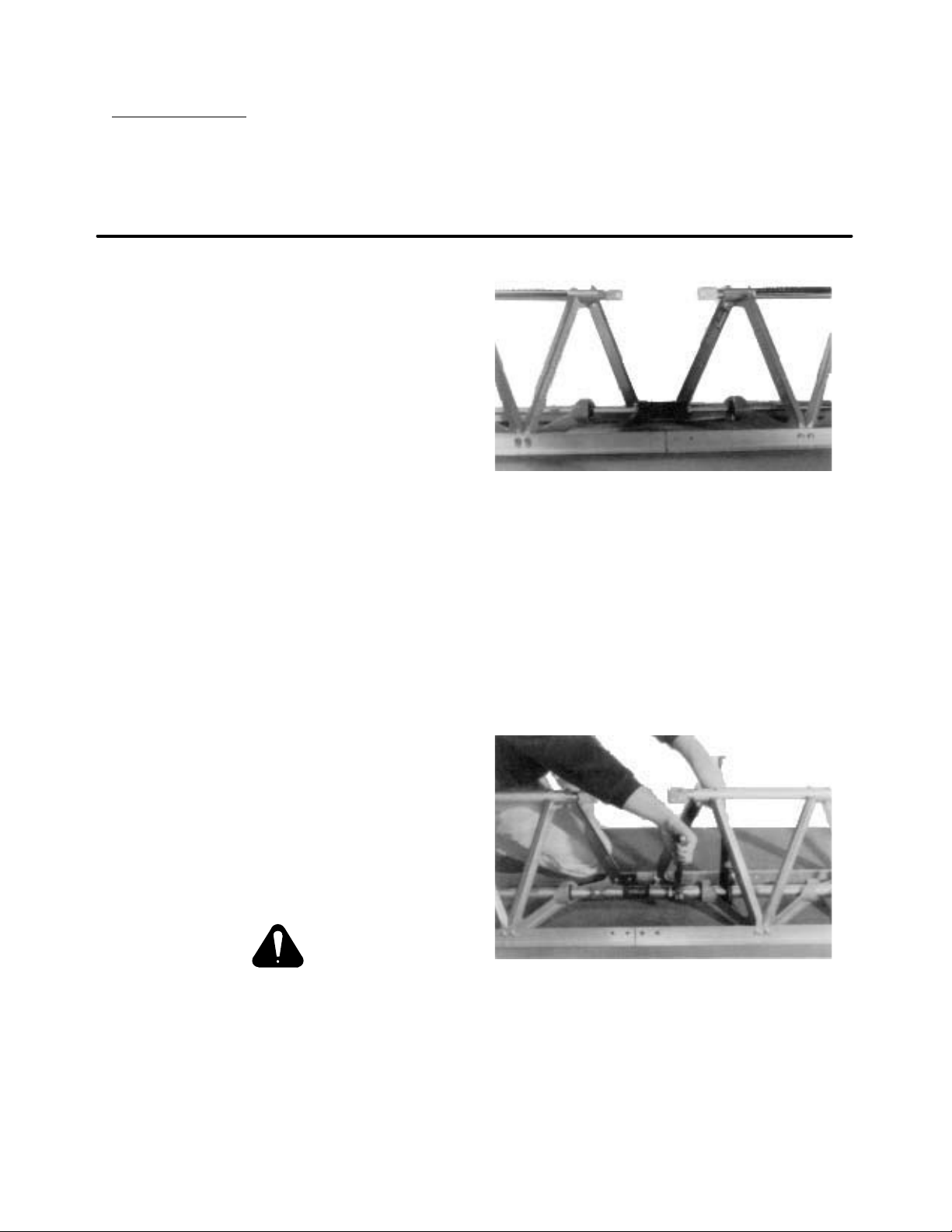
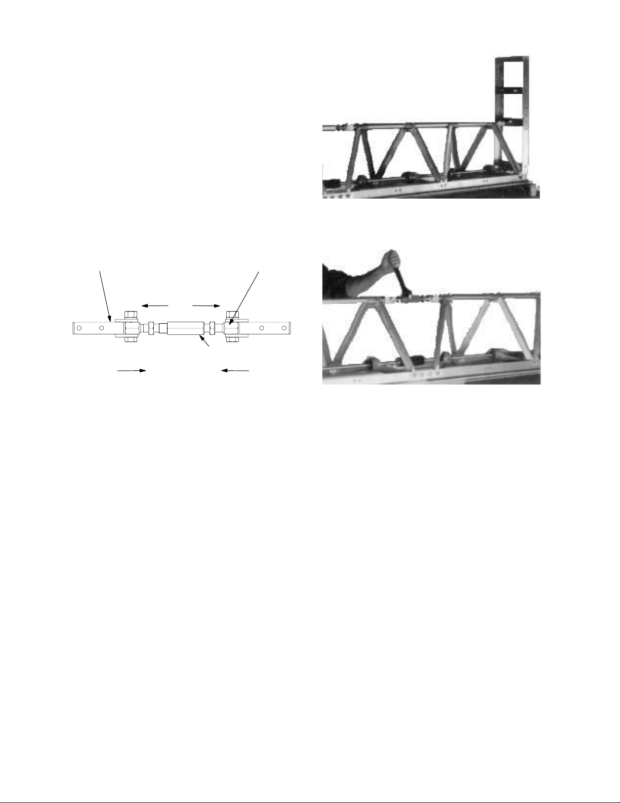
FIGURE 2
For the air screed join the threaded
manifold ends with a manifold hose.
Use a pipe wrench to prevent the manĆ
ifold from turning while the hose ends
are tightened onto the manifold ends
(see Figure 3). Assemble all sections in
this manner. Sight down top tubes of all
sections joined and straighten sections
if necessary.
5. Start assembling sections at one end of
the screed. For mechanical screeds
place a flex coupling along with two flex
coupling collars between the two couĆ
pling drivers of adjoining sections. ColĆ
lars should be slid out to the ends of the
flex coupling (see Figure 2).
IMPORTANT !
Check that the two vibrating shaft
offsets are in line.
Assemble all sections in this manner.
Sight down top tubes of all sections
joined and straighten sections if necesĆ
sary.
FIGURE 3
6. Install a two bolt splice plate thru float
edging. Install a four hole splice plate
on the outside of edging and loosely
install four blind nuts (see Figures 4 and
5).
11
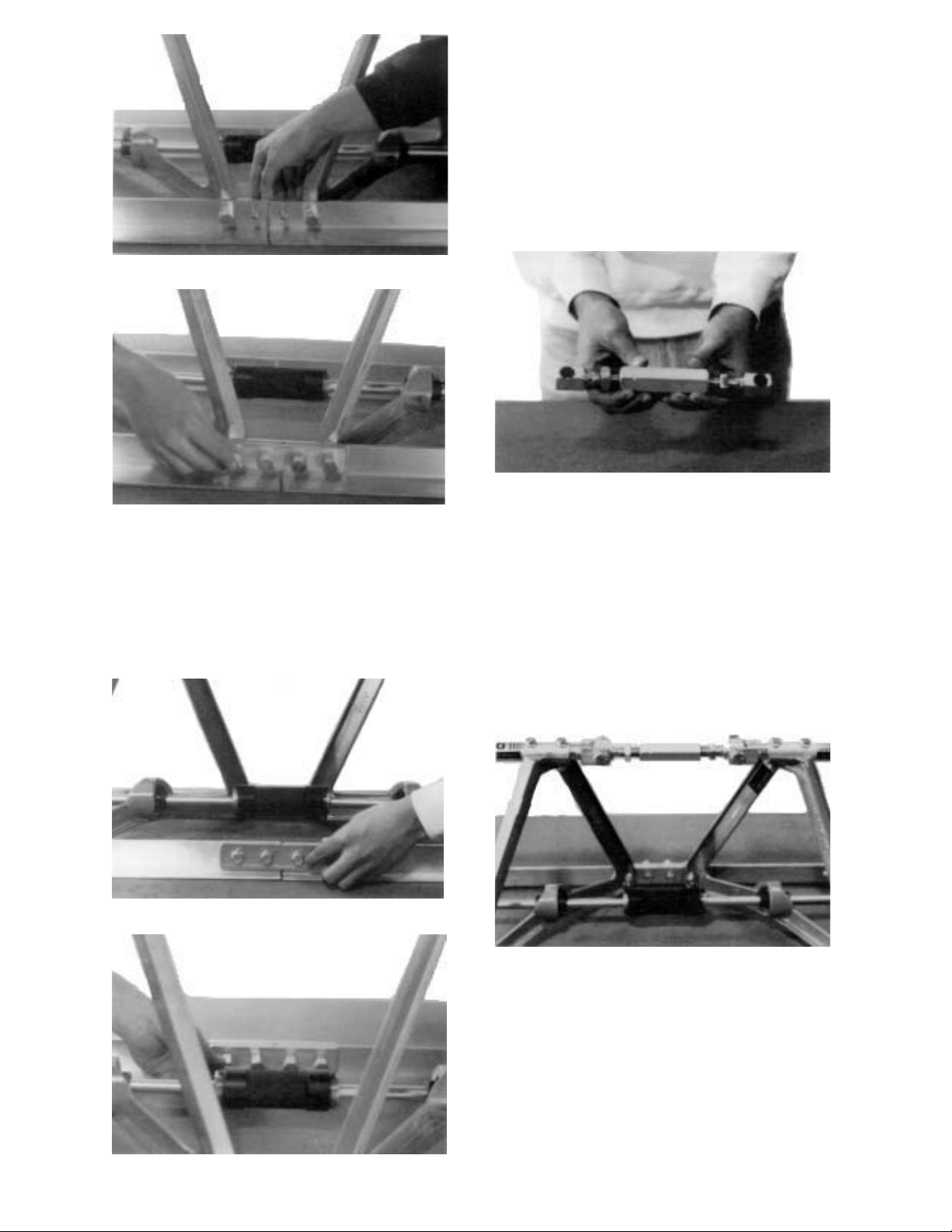
FIGURE 4
8. Make sure the bottom of the four edgĆ
ings are in the same plane. Tighten
both splice plates hard.
9. Take a right turnbuckle eye and install a
right-hand jam nut about three quarĆ
ters of the way up the shaft. Now install
the eye onto the turnbuckle a little over
half way. Do the same with the left turnĆ
buckle eye (see Figure 8).
FIGURE 8
FIGURE 5
7. Install a four bolt splice plate thru the
strikeoff edging. Install a four hole
splice plate on the inside of the edging
and loosely install 4 blind nuts (see FigĆ
ures 6 and 7).
FIGURE 6
10.Loosely install the turnbuckle assembly
directly above the flex coupling to both
clevises using a 5/8-18 X 2-1/2 bolt,
lockwasher, and a hex nut (see Figure
9). Install all the turnbuckles in the
same direction as you progress
down the screed. There is a notch cut
on one end of the turnbuckle to indicate
its direction. Remember, do not tighten
the turnbuckle hardware yet.
FIGURE 7
FIGURE 9
12
REPEAT STEPS 6 - 10 UNTIL ENTIRE SCREED IS ASSEMBLED.
After all needed sections are assembled
the edging can be trued horizontally.
11.If the pour surface is to be crowned or
flat, rotate the turnbuckles so the turnĆ
buckle eyes are pushed away from
each other taking out the slack at the
clevis connections. If the pour surface
is a valley, rotate the turnbuckles so the
turnbuckle eyes are drawn towards
each other taking out the slack at the
clevis connections (see Figure 10).
Tighten down the 5/8 bolts going
through the clevises and turnbuckle
eyes HARD once the slack is removed.
FIGURE 11
Clevis
Crowned or Flat
Valley
Turnbuckle Eye
Turnbuckle
FIGURE 10
12. The screed is now ready for grade adĆ
justment. Place the assembled screed
on blocks or forms. String a taut chalk
line across the back of the float edge of
the screed (see Figure 11). Start with
the centermost turnbuckle and adjust it
so the bottom edge of the screed
moves up or down until it is adjusted to
the desired grade (see Figure 12). AdĆ
just each turnbuckle, working out from
the center, until the desired grade is
achieved. As the turnbuckles are adĆ
justed from the center out, previously
adjusted turnbuckles may need to be
readjusted to grade. Readjust the cenĆ
termost turnbuckles and continue adĆ
justing outward. When all adjustments
are completed, hold the turnbuckle
from further movement and tighten the
jam nuts.
FIGURE 12
CAUTION!
If there is a significant difference beĆ
tween the ambient temperature at set up
and the temperature of the concrete to
be screeded, the edgings may warp due
to thermal expansion. Recheck the
grade of the screed if this is the case.
13
ENGINE ASSEMBLY
GENERAL
The engine can be put on any mechanical screed section on the left end where there are
bearings in two adjacent A-frames.
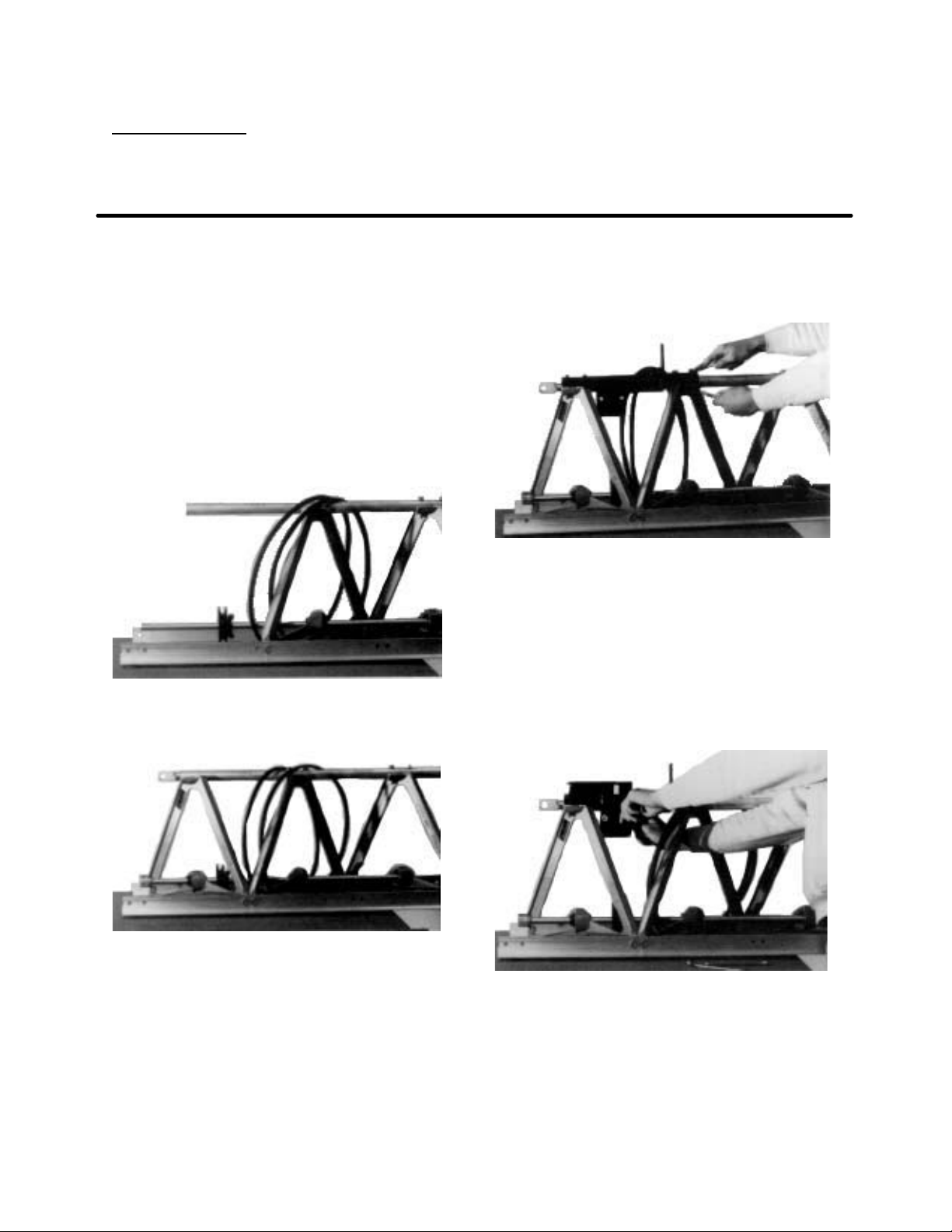
1. To install sheave, first remove left couĆ
pling driver. Support end of shaft when
driving out the spiral pin. Now remove
left end A-frame and clevis. Slide
#09126 sheave onto main shaft. Also
put both V-belts, supplied with engine
kit, around main shaft and over top of
the top tube (see Figure 13). ReassemĆ
ble left A-frame, clevis and coupling
driver (see Figure 14). Do not install the
top tube bolts at this time.
FIGURE 13
ing bracket thru holes aligned above
(See Figure 15). These bolts replace
the original 3/8-16 X 2 bolts that were
removed earlier.
FIGURE 15
3. Place engine mounting deck (#09787)
on top of mounting bracket installed in
Step 2. Loosely install engine mountĆ
ing deck using four whiz-lock bolts
and flange nuts thru slots in mounting
deck and thru holes in mounting brackĆ
et (see Figure 16). The mounting deck
should be in its lowest position.
FIGURE 14
2. Remove the two top tube bolts from
right A-frame next to left A-frame reĆ
moved in Step 1. Set #09090 mounting
bracket on top tube and align holes up
over the two A-frames. Use four
3/8-16 X 2-1/2 bolts to secure mountĆ
FIGURE 16
4. Bolt engine tight to the mounting deck
using four engine mounting bolts,
washers and flange nuts (see Figure
17).
14
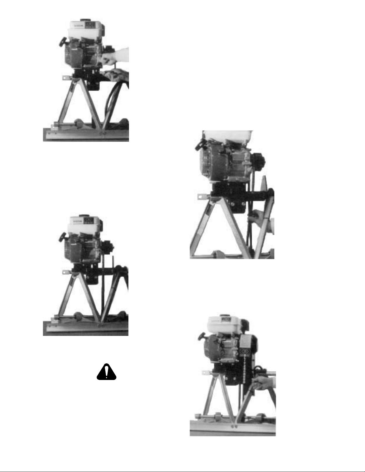
FIGURE 17
5. Slip one V-belt over engine clutch.
Place V-belt on sheave and align
sheave with engine clutch. Secure
spare V-belt to an A-frame using tie
wraps (see Figure 18).
7. Adjust belt tension by sliding engine
mounting deck upward in slots. Check
belt tension by pinching belt between
your fingers.
Single Belt - The two sides of the belt
should touch or go slightly past each
other (see Figure 19).
Dual Belt - A 2" gap should remain beĆ
tween the two sides of both belts.
Tighten the four whiz-lock bolts holding
the engine mounting deck to the
mounting bracket. NOTE: Do not over
tighten belt.
FIGURE 18
Make sure the shaft is rotated to its
lowest position at this time. (set
screws in bearings are up).
6. Rotate pulley so the thick side of bore
is on top of the shaft. Tighten sheave
onto shaft by tightening the two screws
in the tapered bushing of sheave.
FIGURE 19
8. Bolt the belt guard to the mounting
bracket using three 5/16-18 X 1/2
screws (see Figure 20).
FIGURE 20
15
 Loading...