

MBW AT84 User Manual
OPERATOR’S SAFETY
AND SERVICE MANUAL
AT73
AT84
This manual covers the following serial numbers
and higher for each model listed:
ATS73 . . . . . . . . . . . . . . . . . . . . 4070001
ATP73 . . . . . . . . . . . . . . . . . . . . 4070001
ATS84 . . . . . . . . . . . . . . . . . . . . 4080001
ATP84 . . . . . . . . . . . . . . . . . . . . 4080001
SKID-STEER ROLLER ATTACHMENTS
MBW, Inc.
250 Hartford Rd • PO Box 440
Slinger, WI 53086-0440
Phone: (262) 644-5234
Fax: (262) 644-5169
Email: mbw@mbw.com
Website: www.mbw.com
MBW (UK) Ltd.
Units 2 & 3 Cochrane Street
Bolton BL3 6BN, England
Phone: 44 (0) 01204 387784
Fax:44 (0) 01204 387797
MBW France S.A.R.L
Z.A. d’Outreville
5 rue Jean Baptiste Néron,
60540 BORNEL
France
Phone: +33 (0) 3 44 07 15 96
Fax: +33 (0) 3 44 07 41 28
L17993 / 05.11.E
©MBW, Inc. 2007
Printed in the USA

TABLE OF CONTENTS
Safety Information . . . . . . . . . . . . . . . . . . . . . . 1
Introduction . . . . . . . . . . . . . . . . . . . . . . . . . . . . . . . . . 1
Safety Precautions . . . . . . . . . . . . . . . . . . . . . . . . . . . 1
Safety Decals . . . . . . . . . . . . . . . . . . . . . . . . . . . . . . . 1
Specifications. . . . . . . . . . . . . . . . . . . . . . . . . . 3
Operation . . . . . . . . . . . . . . . . . . . . . . . . . . . . . 4
Introduction . . . . . . . . . . . . . . . . . . . . . . . . . . . . . . . . . 4
Before Starting & Operating . . . . . . . . . . . . . . . . . . . . 4
Connecting to Loader . . . . . . . . . . . . . . . . . . . . . . . . . 4
Operating . . . . . . . . . . . . . . . . . . . . . . . . . . . . . . . . . . 4
Maintenance . . . . . . . . . . . . . . . . . . . . . . . . . . . 5
Maintenance Schedule . . . . . . . . . . . . . . . . . . . . . . . . 5
Fluid Levels. . . . . . . . . . . . . . . . . . . . . . . . . . . . . . . . . 5
Changing Exciter Oil . . . . . . . . . . . . . . . . . . . . . . . . . . 5
Checking Exciter Oil . . . . . . . . . . . . . . . . . . . . . . . . . . 6
Service. . . . . . . . . . . . . . . . . . . . . . . . . . . . . . . . 7
Torque Chart . . . . . . . . . . . . . . . . . . . . . . . . . . . . . . . 7
Service Tools . . . . . . . . . . . . . . . . . . . . . . . . . . . . . . . 7
Replacing Shockmounts. . . . . . . . . . . . . . . . . . . . . . . 7
Replacing Input Seal . . . . . . . . . . . . . . . . . . . . . . . . . 7
Removing Drive Coupler . . . . . . . . . . . . . . . . . . . . . . 7
Installing Drive Coupler . . . . . . . . . . . . . . . . . . . . . . . 8
Removing Exciter Bearings and Shaft.. . . . . . . . . . . . 8
Installing Exciter Bearings and Shaft.. . . . . . . . . . . . . 8
Parts Replacement Cycles and Tolerances . . . . . . . . 9
Replacement Parts . . . . . . . . . . . . . . . . . . . . . 11
Drum Assembly . . . . . . . . . . . . . . . . . . . . . . . . . . . . 12
Main Assembly . . . . . . . . . . . . . . . . . . . . . . . . . . . . . 14
Spider Assembly . . . . . . . . . . . . . . . . . . . . . . . . . . . 16
Warranty . . . . . . . . . . . . . . . . . . . . . . . . . . . . . 18

WARNING
CALIFORNIA PROPOSITION 65 WARNING
Engine exhaust and some of its constituents are
known in the state of California to cause cancer,
birth defects, and other reproductive harm.

SAFETY INFORMATION
Introduction
This Safety Alert Symbol is used to call attention
to items or operations which may be dangerous
to those operating or working with this
equipment. The symbol can be found
throughout this manual and on the unit. Please read these
warnings and cautions, along with all decals, carefully
before attempting to operate the unit. Make sure every
individual who operates or works with this equipment is
familiar with all safety precautions.
WARNING
GENERAL WARNING. Indicates information
important to the proper operation of the
equipment. Failure to observe may result in
damage to the equipment and/or severe bodily
injury or death.
CAUTION
GENERAL CAUTION. Indicates information
important to the proper operation of the
equipment. Failure to observe may result in
damage to the equipment.
Safety Precautions
LETHAL EXHAUST GAS: An internal
combustion engine discharges carbon
monoxide, a poisonous, odorless, invisible
gas. Death or serious illness may result if
inhaled. Operate only in an area with proper
ventilation. NEVER OPERATE IN A
CONFINED AREA!
DANGEROUS FUELS: Use extreme caution
when storing, handling and using fuels, as
they are highly volatile and explosive in vapor
state. Do not add fuel while engine is running.
Stop and cool the engine before adding fuel.
DO NOT SMOKE!
SAFETY GUARDS: It is the owner's
responsibility to ensure that all guards and
shields are in place and in working order.
IGNITION SYSTEMS: Breakerless, magneto,
and battery ignition systems can cause severe
electrical shocks. Avoid contacting these
units or their wiring.
SAFE DRESS: Do not wear loose clothing,
rings, wristwatches, etc. near machinery.
NOISE PROTECTION: Wear OSHA specified
hearing protection devices.
EYE PROTECTION: Wear OSHA specified
eye shields, safety glasses, and sweat bands.
FOOT PROTECTION: Wear OSHA specified
steel-tipped safety shoes.
HEAD PROTECTION: Wear OSHA specified
safety helmets.
DUST PROTECTION: Wear OSHA specified
dust mask or respirator.
OPERATOR: Keep children and bystanders
off and away from the equipment.
REFERENCES: For details on safety rules and regulations
in the United States, contact your local Occupational Safety
and Health Administration (OSHA) office. Equipment
operated in other countries must be operated and serviced
in accordance and compliance with any and all safety
requirements of that country. The publication of these
safety precautions is done for your information. MBW does
not by the publication of these precautions, imply or in any
way represent that these are the sum of all dangers present
near MBW equipment. If you are operating MBW
equipment, it is your responsibility to insure that such
operation is in full accordance with all applicable safety
requirements and codes. All requirements of the United
States Federal Occupational Safety and Health
Administration Act must be met when operated in areas that
are under the jurisdiction of that United States Department.
Safety Decals
Carefully read and follow all safety decals. Keep them in
good condition. If decals become damaged, replace as
required. If repainting the unit, replace all decals. Decals
are available from authorized MBW distributors. Order the
decal set listed on the following page(s).
- 1 -
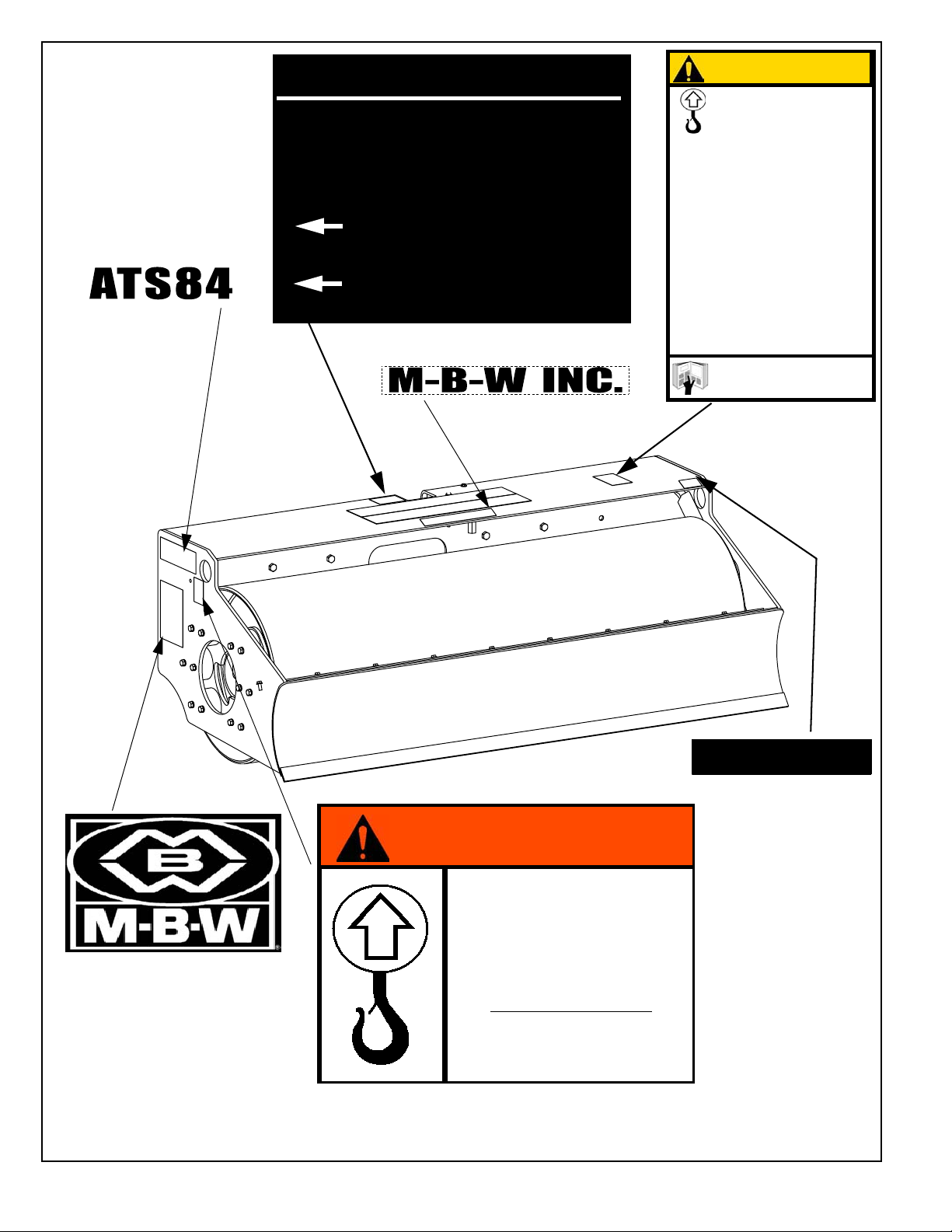
17906 - ATS73
CAUTION
HEAVY
ATTACHMENT
14434
READ OPERATORS MANUAL
BEFORE USING ATTACHMENT
Overloading skid loader
could cause loader to pitch
or tip forward.
Check lifting capacity of skid
loader before hooking onto
attachment.
Do not lift attachment over
12” (30cm) above ground
level.
09867
17907 - ATP73
17908 - ATS84
17909 - ATP84
(NOT IN DECAL SET)
Hydraulic Requirements
PRESSURE: 1500-3000 psi
(103-207 bar)
FLOW: 10-50 gpm
(38-190 l/m)
Return
Pressure
14435
14435
02355
02355
(NOT IN DECAL SET)
14434
Safety Decals (Decal Set #14436)
(NOT IN DECAL SET)
09867
11922
WARNING
Machine may fall and cause
serious damage or injury if
lifted improperly.
Lift only by holes in frame
above.
MACHINE WEIGHT
ATS84- 2300 lbs (1043 kg)
ATP84- 2450lbs (1111 kg)
18075
18075-AT84
18074-AT74 (Not Shown)
- 2 -
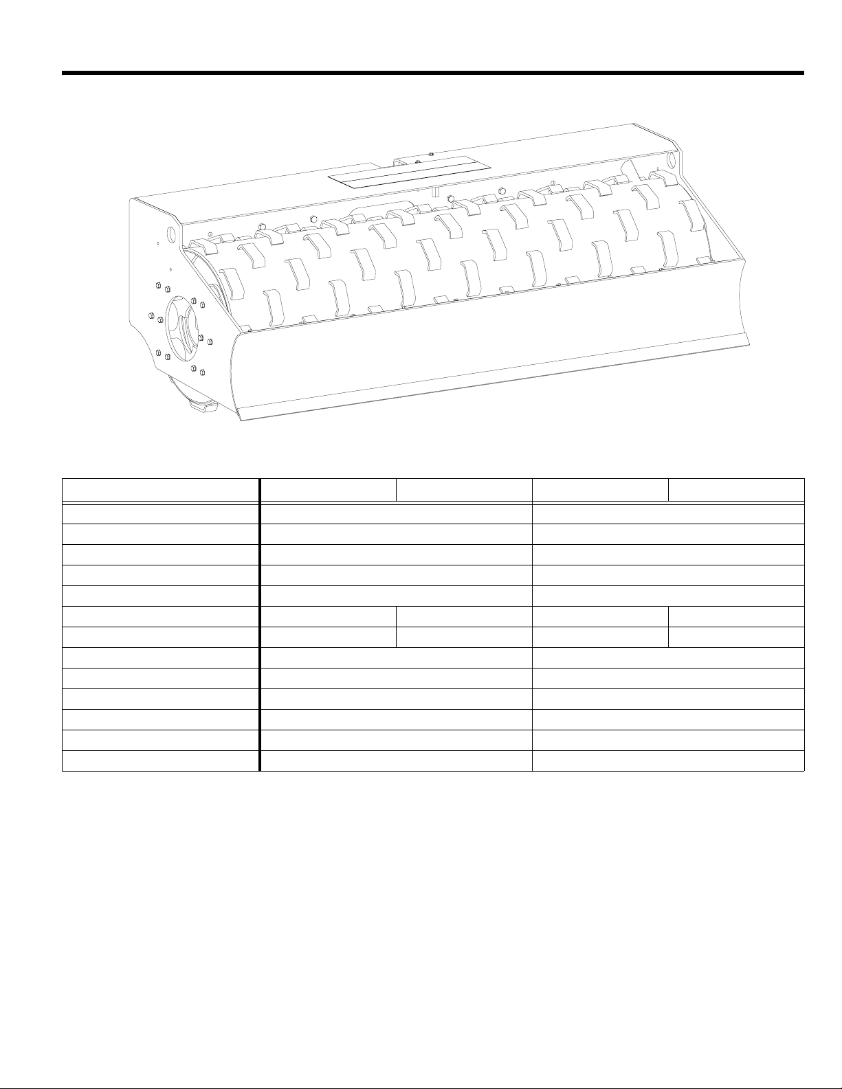
SPECIFICATIONS
ATP84
ATS73 ATP73 ATS84 ATP84
Centrifugal Force 8850 lbs (4014 kg) 9765 lbs (4429 kg)
Exciter Speed 3000 rpm 3000 rpm
Dynamic Linear Force 121 lb/in (21.7 kg/cm) 116 lb/in (20.8 kg/cm)
Amplitude --
Length 43.3 in (110 cm) 43.3 in (110 cm)
Height 29 in (74 cm) 30 in (76 cm) 29 in (74 cm) 30 in (76 cm)
Weight 2070 lbs (939kg) 2210 lbs (1002 kg) 2300 lbs (1043 kg) 2450 lbs (1111 kg)
Width, Working 73 in (185 cm) 84 in (213 cm)
Width, Overall 78 in (198 cm) 89 in (226 cm)
Sound Pressure Level 85 dBa 85 dBa
Pressure Requirement 1500 - 3000 psi (10.3 - 20.7 MPa) 1500 - 3000 psi (10.3 - 20.7 MPa)
Flow Rate Requirement 10 - 50 GPM (38 - 176 LPM) 10 - 50 GPM (38 - 176 LPM)
Connection 1/2” Flat-face Quick Coupling 1/2” Flat-face Quick Coupling
Specifications subject to change without notice
- 3 -
OPERATION
Introduction
MBW equipment is intended for use in very severe
applications.
This parts manual contains only standard parts. Variations
of these parts as well as other special parts are not included.
Contact your local MBW distributor for assistance in
identifying parts not included in this manual.
Before Starting & Operating
• REMEMBER! It is the owner’s responsibility to
communicate information on the safe use and proper
operation of this unit to the operators.
• Review ALL of the Safety Precautions listed on page 1 of
this manual.
• Familiarize yourself with the operation of the machine
and confirm that all controls function properly.
• Know how to STOP the machine in case of an
emergency.
• Make sure hands, feet, and clothing are at a safe
distance from any moving parts.
4. Lower the roller, and engage the loaders’ arms into
their float mode.
5. Engage the auxiliary hydraulics and allow the vibrator
to come up to speed.
Operating
• Check for loose hardware every 20 hours of operation.
• Do not run exciter when roller is not in contact with the
ground.
• Check that rated capacity of skid steer loader meets or
exceeds weight of roller attachment.
• The operating pressure supplied to the control valve
must fall in the range of 1500 to 3000 psi.
• The minimum volume requirement supplied to the control
valve is 10 gpm, but do not exceed 50 gpm.
• Do not use excessive down pressure when compacting
soil.
WARNING
Always stop the engine before:
Connecting to Loader
1. Attach the roller to the skid steer loader with the
universal bracket. Be sure that the wedges and
levers are fully engaged and locked.
2. Connect the hydraulic hoses to the skid steer loader’s
auxiliary hydraulics supply using the quick couplers.
3. If skid loader is equipped with a high flow and low flow
ports, it is recommended to use the low flow side.
Adding fuel.
Leaving the equipment unattended for any
amount of time.
Before making any repairs or adjustments to the
machine.
- 4 -
 Loading...