

MBW 973-SF6 Operation Manual
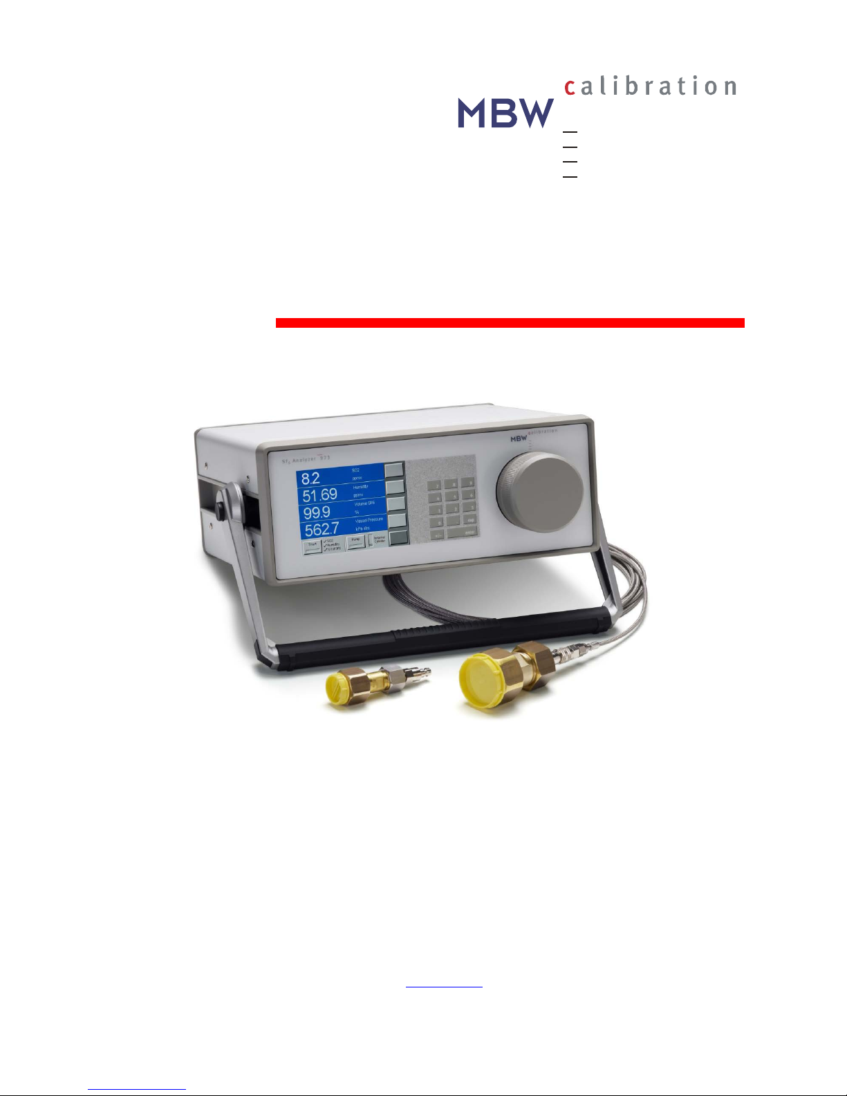
SF6 Analyzer 973
Operation Manual
Version 973-SF6
V3.1
MBW Calibration Ltd.
Seminarstrasse 57
CH-5430 Wettingen / Switzerland
+41 56 437 28 30 Phone
+41 56 437 28 40 Fax
sales@mbw.ch
www.mbw.ch


MBW973-SF6_MANUAL_E_V3.1 i
Table of Contents
TABLE OF CONTENTS ...................................................................................... I
GENERAL .......................................................................................................... 1
SHORT DESCRIPTION ...................................................................................... 3
OPERATION....................................................................................................... 5
Front Panel without SO2 Option ................................................................................................. 5
Front Panel with SO2 Option ...................................................................................................... 5
Back Panel without SO2 Option ................................................................................................. 8
Back Panel with SO2 Option ...................................................................................................... 8
INITIAL SETUP ................................................................................................ 11
Preparation ............................................................................................................................... 11
Electrical Connection ............................................................................................................... 11
Connection of the Serial Interface ............................................................................................ 11
SF6 Gas Connection ................................................................................................................ 12
Evacuate the Sampling Tube ................................................................................................... 13
Evacuate the Internal Cylinder ................................................................................................. 14
SF6 Gas Connection to the Compartment ............................................................................... 15
MEASUREMENT OPTIONS ............................................................................. 17
Navigating the Menus .............................................................................................................. 17
MEASUREMENT .............................................................................................. 19
Measurement without SO2 Option ........................................................................................... 19
Termination of Measurement ................................................................................................... 20
Measurement with SO2 Option................................................................................................. 21
Termination of Measurement ................................................................................................... 22
Measuring Range Limitations .................................................................................................. 23
Alarm Messages ...................................................................................................................... 23
Measurement Aborted ............................................................................................................. 24
Measurement of Air or Nitrogen (N2) ....................................................................................... 24
DATA COLLECTION IN EXCEL ...................................................................... 25
RS-232 – USB Converter Installation ...................................................................................... 25
Data Collection over RS-232 with the Excel Protocol .............................................................. 26
SO2 MODULE ................................................................................................... 29
Replacement of SO2 Measurement Cell .................................................................................. 29
Activation of SO2 Measurement ............................................................................................... 30

ii MBW973-SF6_MANUAL_E_V3.1
TEST FUNCTIONS ........................................................................................... 31
Ice Test .................................................................................................................................... 31
ADDITIONAL SETTINGS ................................................................................. 35
Selection of Languages ........................................................................................................... 35
Selection of the indicated Parameters ..................................................................................... 36
Selection of Units ..................................................................................................................... 37
Changing Color ........................................................................................................................ 38
Storage of the Actual Settings ................................................................................................. 39
Restore Color Settings and Baud Rate .................................................................................... 40
MAINTENANCE ............................................................................................... 41
Touch Screen Calibration ........................................................................................................ 41
Mirror Cleaning ......................................................................................................................... 42
Exterior Cleaning ...................................................................................................................... 43
SPECIFICATIONS ............................................................................................ 45
MBW973-SF6_MANUAL_E_V3.1 1
General
This manual explains the function of the 973-SF6 Analyzer with and without the SO2 option.
Throughout this manual the instrument will be called 973.
This manual refers to instrument software versions 110525a and higher.
Should the 973 be used in any other way than that described in this
user’s manual, or outside the limits described, the built-in safety protection of the instrument may be compromised.
Vol SF6 %
All descriptions in
bold italic
are related to the text on the front panel,
the display and the back panel of the 973.
If you wish to use the instrument as quickly as possible, we recommend reading the chapters
Initial Setup (page 11) and Measurement (page 19). Standard use of the instrument is explained in these two chapters.

2 MBW973-SF6_MANUAL_E_V3.1

MBW973-SF6_MANUAL_E_V3.1 3
Short Description
Reliable Measurements in SF6
The 973 was specifically designed for measurement of humidity, SF6 purity and SO2 concentration in gas insulated switchgear systems. Humidity measurement data is displayed in ppm
v
,
ppm
w
and Frost/Dew Point at either gas compartment pressure or standard pressure. SF6 purity
measurement is displayed directly in % Volume SF
6
. Both the humidity and purity measure-
ments utilize accurate and reliable condensation techniques. SO
2
concentration is measured
with an electrochemical cell with results displayed in ppm
v.
Gas Recovery and Pressure Measurement
The 973 is equipped with a gas recovery system that stores the sampled gas during the measurement process in its internal storage cylinder. After completion of the measurement, the
stored gas is pumped back into the original compartment or into another vessel. The compartment pressure is also measured.
Easy, Automated Measurement
The 973 is equipped with a user configurable full color active matrix LCD with integrated touch
screen. The 973 may be configured for measurement of Humidity and % Volume SF
6
with either
automatic or manually initiated Pump Back. Using the bi-directional RS-232 communications
port, all measurement data may be easily transferred to a computer.
Calibration
Users can easily check the 973 calibration at an y tim e using the bu ilt-in Ice Test function,
providing instant verification of system accuracy and integrity.
LCD Display with Touch Panel
The 973 utilizes a full color active matrix liquid crystal display with an integral touch panel. It has
a high contrast ratio and a wide viewing angle for easy readability. Data is displayed in large,
easy to read fonts. Using the on screen function and menu keys, you can easily configure each
line of the display and navigate the menus.
Versions equipped with the SO
2
option will have alternative display and data line formats.
Please refer to page 21 for further information on the measurement of SO
2
concentration.
Connect and Go
The system is supplied ready for immediate use.
973-SF6 with Standard Accesso ries
• Transport Case
• 6 m Stainless Steel armored PTFE tubing
• SF
6
coupling DN20 and DN8
• 3 m RS-232 cable incl. USB adapter with USB cable
• 2.5 m power cable
• Operation Manual
• CD-ROM

4 MBW973-SF6_MANUAL_E_V3.1
MBW973-SF6_MANUAL_E_V3.1 5
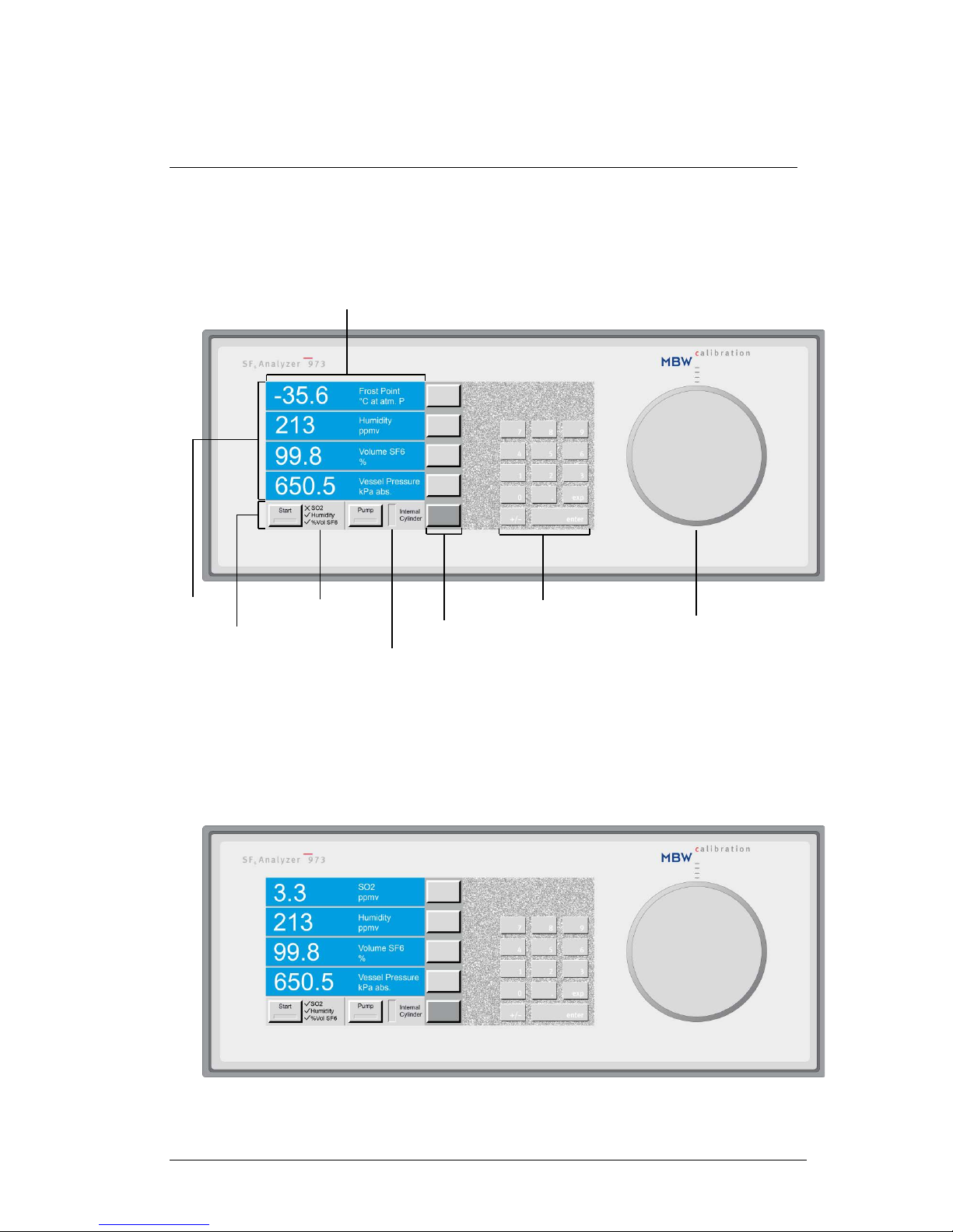
Operation
Front Panel without SO2 Option
Front Panel with SO2 Option
Status of Measurement
Measuring Head
Keypad
Menu Keys
Internal
Cylinder Capacity
Fixed Function Keys
Touch Screen
Data Lines
6 MBW973-SF6_MANUAL_E_V3.1
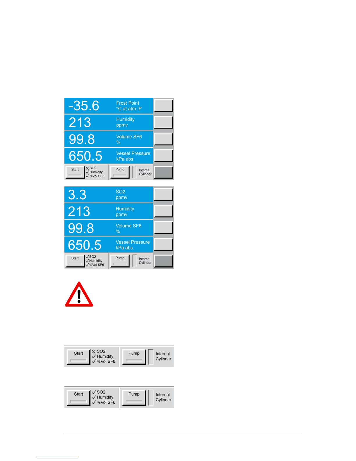
Data Lines
The first four lines of the display are for numeric representation of the measured data. We refer
to those first four lines as Data Lines. Numeric data lines contain the value to the left, with the
parameter description and units to the right. The displayed parameters and units can be
changed, but after a restart of the instrument, the values will be reset to the stored standard
configuration.
Data Line 1
This line displays the measured Dew/Frost Point.
The unit is °C at atmospheric pressure.
In the standard configuration, instruments equipped
with the SO
2
option show the SO2 concentration
expressed in ppm
v
. The standard SO2 configuration
is shown on the second display.
Data Line 2
This line displays the humidity content in either
ppm
v
(parts per million by volume) or ppmw (parts
per million by weight). Both units are pressure in dependent.
Data Line 3
This line displays the purity in % Volume SF
6
.
Data Line 4
This line indicates the current pressure of the gas
compartment. The unit is kilo Pascal absolute pressure.
The data lines indicating the measured humidity and SO2 concentrations as we ll a s
the % Volume SF
6
will only be displayed after completion of the measurement. During the measurement only the current gas pressure of the measured compartment
is indicated.
Fixed Function Keys and Status Line
Without SO2 Option
With SO
2
Option
The bottom line of the display contains two fixed
function keys. The measurement process is started
by pressing the Start button. With the Pump button,
pump back of stored gas in the internal cylinder can
be activated manually. These function keys are not
changeable and are always available. Additionally
this line contains the status indication, which indicates the current operation mode. The level indicator of the internal cylinder indicates the current storage capacity. A 973 without the SO
2
option will dis-
play an X next to SO2 to indicate that the meas-
urement of SO2 concentration is not available.
MBW973-SF6_MANUAL_E_V3.1 7
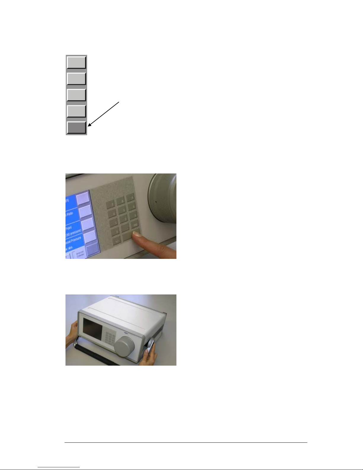
Menu Keys
To the right side of the display is a column of menu
keys. Each of these keys changes function as
needed.
Note that the bottom key in this column is diff erent
from the rest. The bottom key is used to cycle the
upper keys through the various menu options. The
text on the bottom key changes to indicate the currently selected menu option. The text of the upper
keys change based on the functions available in the
menu.
Keypad
The keypad is used for entering data into the 973.
For normal operation it is rarely used.
Carrying Handle
To adjust the position of the carrying handle, press
the buttons on both sides to unlock it before rotating. Release the buttons when the desire d pos ition
is found.
Use the
bottom
key to
change
menus
8 MBW973-SF6_MANUAL_E_V3.1
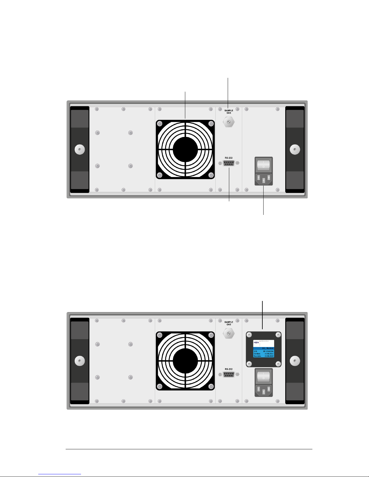
Back Panel without SO2 Option
Back Panel with SO2 Option
Fan
Gas Inlet
Quick Coupling
RS-232
Serial Interface
Power Socket
with Main Switch
Optional SO2 Sensor
with Calibration Date
and Replacement Date

MBW973-SF6_MANUAL_E_V3.1 9
Power Connection
The AC power cord is connected to the power socket on the instrument back panel. The power
socket also includes the power switch. The power supply voltage is 100-120 VAC /
200-240 VAC at 50 to 60Hz. The power supply is internally fused and will automatically switch
off in case of an overload. To restart the power supply, the instrument main switch must be
switched to 0 and I again.
SO2-Module
When fitted, the SO2 module is mounted to the back panel of the 973 which allows the SO2 sensor to be easily replaced by the user. The sensor has to be replaced every two years. The calibration and replacement dates are indicated on the SO
2
module.
Gas Inlet Quick Coupling
The sampling line is connected to the sample gas inlet. If the instrument is not in use the inlet
should be protected with the blue cover.
RS-232 Serial Interface Connector
The RS-232 connector is used when connecting the 973 to a computer. Use the supplied 9 pin
1:1 cable to connect the 973 to a desktop or laptop computer. This cable has a male connector
on one end and a female connector on the other end. It is most often referred to as a serial extension cable.
Fan
When the 973 is switched on, the cooling fan always runs independent of the ambient and instrument temperatures.

10 MBW973-SF6_MANUAL_E_V3.1
MBW973-SF6_MANUAL_E_V3.1 11
Initial Setup
Preparation
The 973 needs a source of normal AC power. The label on the back panel indicates the acceptable input voltage range. The instrument has been designed to work with a power range
between 100-120 VAC / 200-240 VAC at 50 to 60 Hz. This normally covers all usual AC line
voltages.
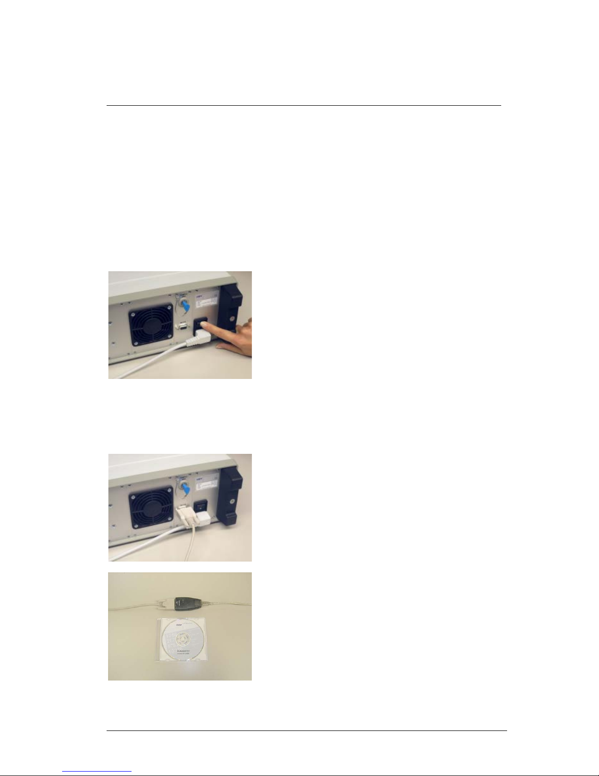
Electrical Connection
The power socket and the main power switch are on the back
panel of the instrument. Use the provided power cable to
connect the instrument to the AC power.
Start the instrument by turning on the power switch. The display of the 973 comes up immediately following the processor’s boot phase. The boot phase may take several seconds
to complete.
Connection of the Serial Int e rf a c e
If you intend to transfer the measured data to a computer,
connect the serial cable between the instrument and the
computer.
If your computer is equipped with a USB interface, you can
use the provided RS-232/USB converter. You will find the
drivers on the CD. The installation and data collection will be
explained in the chapter Data Collection in Excel on
page 25.
 Loading...