

MBW 473-RP2, 473-SH2, 473-SH3, 473-SHX Maintenance Manual

Operation and
Maintenance Manual
V5.0
Dew Point Mirror 473


MBW 473 Manual English V5.0 i
Warranty
MBW Calibration AG. (MBW) guarantees that its products are manufactured to the highest quality of
material and workmanship specifications. MBW guarantees the reliability of its products for a period of
24 months from the date of initial shipment when operated in normal use and within the specified design limitations. Under this Warranty, MBW will, at its discretion, repair or replace any component that
upon examination by MBW or its duly authorized representatives proves to be defective during the
warranty period provided the system is returned to the factory for inspection and repair shipping prepaid. Improper or unauthorized maintenance, storage, repair, or alteration of any kind by personnel
other than MBW or its duly authorized representatives may void all warranties. Warranty may also be
voided for misuse, neglect, accident, corrosion, and improper installation. This Warranty is exclusive
and in lieu of any and all other warranties of merchantability, fitness for a particular purpose, or any
other warranty, expressed or implied, and all other liabilities and obligations on the part of MBW. MBW
will not be liable for any other claims or damages, either direct, indirect, or consequential arising out of
the use of its products.
Original manuals are supplied in English and German. Translations in other languages are available,
but in the event of any discrepancy, the German or English versions will be considered as the official
version.
Subject to change without notice.
For the latest version of this manual please visit our website.
Copyright © 2018
2018-04-30
MBW Calibration AG
Seminarstrasse 55/57
CH-5430 Wettingen / Switzerland
+41 56 437 28 30 phone
+41 56 437 28 40 fax
sales@mbw.ch
www.mbw.ch

ii MBW 473 Manual English V5.0

MBW 473 Manual English V5.0 iii
Table of Contents
WARRANTY ..................................................................................................... I
TABLE OF CONTENTS .................................................................................. III
1 SAFETY INSTRUCTIONS ........................................................................... 1
2 KEY FEATURES ........................................................................................ 3
3 QUICK START ........................................................................................... 5
3.1 Unpacking .......................................................................................................................................5
3.2 Installing the Measuring Heads ......................................................................................................6
3.3 Starting your 473 ............................................................................................................................7
3.4 Dew Point Measurement ................................................................................................................7
4 GET TO KNOW YOUR 473 ......................................................................... 9
4.1 Front Panel .....................................................................................................................................9
4.2 Touch Screen .............................................................................................................................. 12
4.3 Back Panel .................................................................................................................................. 13
4.4 Measuring Heads ........................................................................................................................ 18
4.5 Carrying Handle ........................................................................................................................... 23
5 SYSTEM CONFIGURATION ..................................................................... 25
5.1 The Menu .................................................................................................................................... 25
5.2 Selection of indicated Parameters ............................................................................................... 26
5.3 Selection of Numeric or Graphic Data Display ............................................................................ 27
5.4 Control Setup ............................................................................................................................... 30
5.5 Selection of Units......................................................................................................................... 35
5.6 Selection of Color ........................................................................................................................ 36
5.7 Configuration of Optional Analog Outputs ................................................................................... 37
5.8 Diagnostic Functions ................................................................................................................... 39
6 SET UP AND OPERATION ....................................................................... 43
6.1 Measurement Set Up................................................................................................................... 43
6.2 External Temperature .................................................................................................................. 44
6.3 Application Integration ................................................................................................................. 45

iv MBW 473 Manual English V5.0
7 REMOTE COMMUNICATION ................................ .................................... 49
7.1 Hardware Connection and Cabling .............................................................................................. 49
7.2 Communication Settings .............................................................................................................. 50
7.3 Command Syntax ........................................................................................................................ 50
7.4 Command Reference ................................................................................................................... 52
8 MAINTENANCE ........................................................................................ 55
8.1 Calibrate the Touch Screen ......................................................................................................... 55
8.2 Mirror Cleaning ............................................................................................................................ 56
8.3 Exterior Cleaning ......................................................................................................................... 57
8.4 Peltier Cooling Test ..................................................................................................................... 58
8.5 Periodic Maintenance Checks ..................................................................................................... 58
9 ERROR MESSAGES ................................................................................. 59
9.1 Reversible Error Messages ......................................................................................................... 59
9.2 Irreversible Error Messages......................................................................................................... 59
9.3 Fan failure SHX ........................................................................................................................... 60
10 SPECIFICATIONS ................................................................................. 61
11 DRAWINGS ........................................................................................... 63
11.1 Display Unit .................................................................................................................................. 63
11.2 Measuring Heads ......................................................................................................................... 65
12 FAQ’S ................................................................................................... 69

MBW 473 Manual English V5.0 1
1 Safety Instructions
• Disconnect power supply before opening
the instrument housing or connecting / disconnecting
sensors.
• Measuring head may get hot during operation.
Instruments built for the SH3 measuring head
supply more power through the measuring head
cable. Therefore you must not connect an SH2
or RP2 measuring head to these display units,
as it will damage the measuring heads.

2 MBW 473 Manual English V5.0

MBW 473 Manual English V5.0 3
2 Key Features
Precise and Stable Humidity Measurement
With the 473 Dew Point Mirror you are able to perform precise dew point measurements as well as
measurements of other parameters such as relative humidity. The humidity measurement of the 473 is
based on chilled mirror condensation technology which provides highly precise, stable and repeatable
results.
Remote Measuring Heads with Temperature Probe
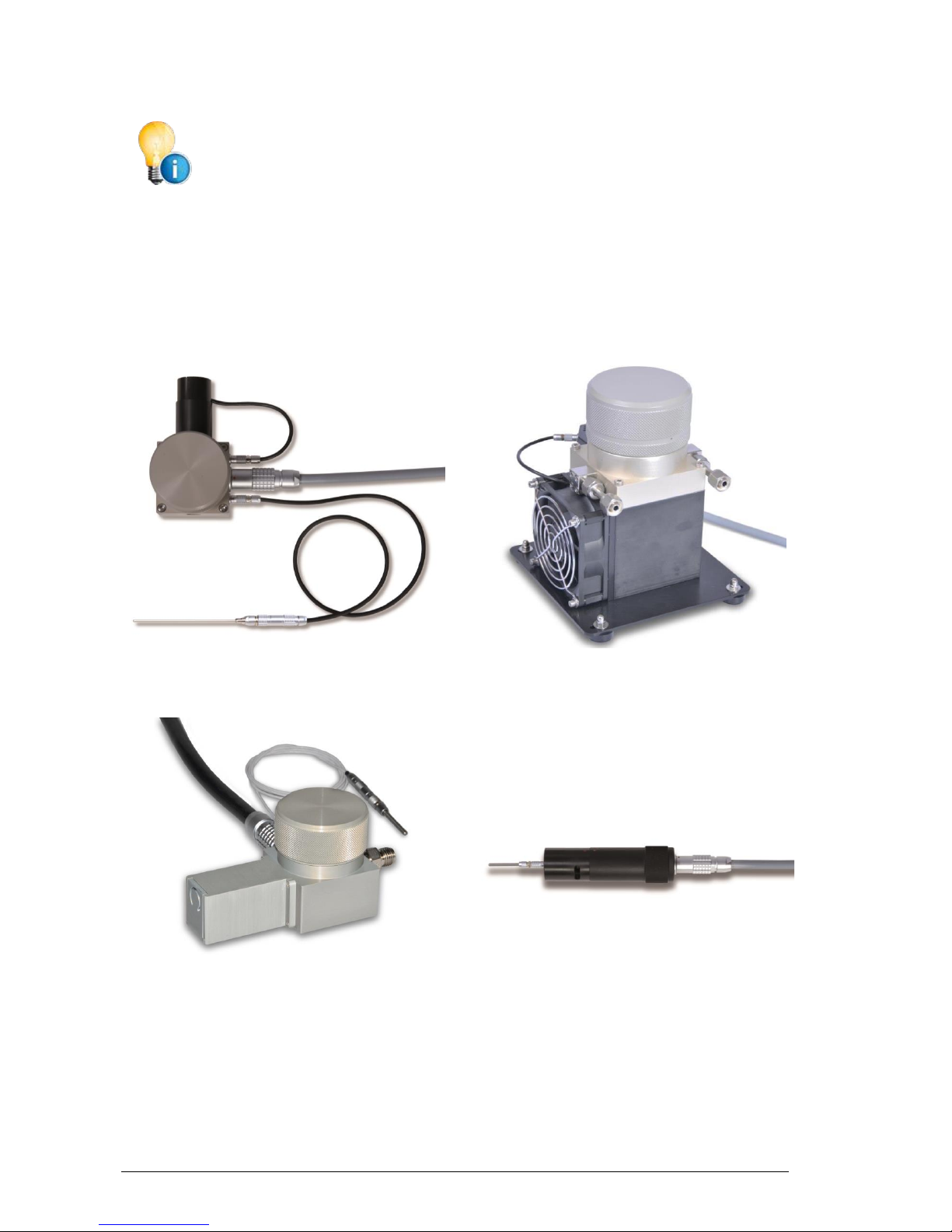
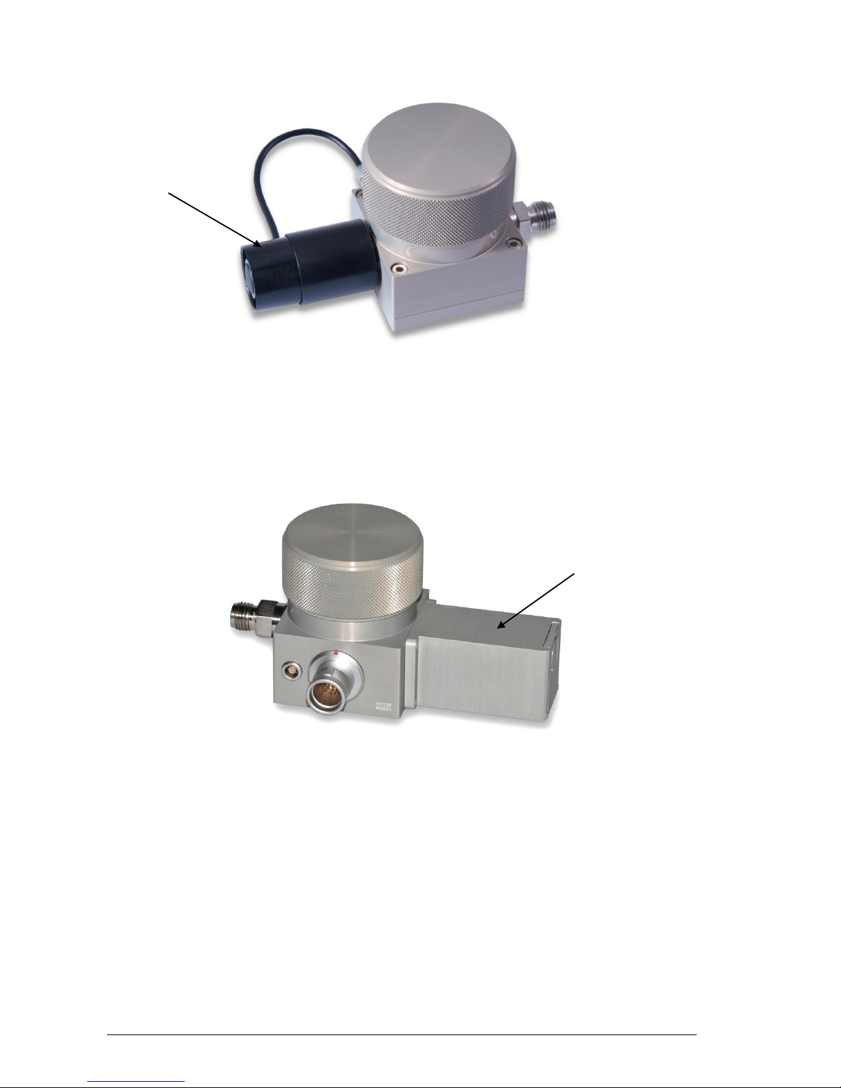
The 473 features remote cable mounted measuring head options, the RP2, SH2, SH3 and SHX. They
are designed for direct placement into applications. Measuring heads are available with a PRT for
precise temperature measurement and for the calculation of relative humidity.
Optional Pressure Measurement
Optionally, the 473 can be ordered with internal pressure measurement capability. This enables the
user to measure barometric pressure or pressure at the point of measurement.
LCD Display with Touch Panel
The 473 has a full color LCD touch panel with a high contrast ratio and a wide viewing angle for easy
readability. Data is displayed in large, easy-to-read fonts. Using the on-screen buttons and menus,
you can easily configure each line of the display for a variety of humidity, temperature, and pressure
parameters that may be viewed in either SI or non-SI units.
Calibration Check Function
Users can check the 473 calibration at any time using the built-in Ice Test function, which provides
instant verification of system accuracy and integrity.
Connect and Go
The system is ready for immediate use.

4 MBW 473 Manual English V5.0

MBW 473 Manual English V5.0 5
3 Quick Start
This section guides you through the set-up and the first steps using your 473. It is a summary and
should be used as a general overview and reference only. Do not use it as a substitute for the remainder of the manual. To understand your instrument thoroughly, please read the other sections carefully.
3.1 Unpacking
The 473-RP2, SH2 and SHX are delivered in a custom-fit foam-lined Peli 1550 transport case. The
473-SH3 is supplied in a cardboard carton and does not include the external PRT as standard.
The following items are included in the case:
• 473 Display Unit
• RP2, SH2, SH3 or SHX measuring head (as ordered)
• Temperature probe. Platinum Resistance Thermometer1 (PRT)
o The RP2 is supplied with a Ø3 x 30 mm PRT and a 0.5 m cable for extended connection
between the probe and the measuring head and a 3 m cable to connect the probe directly to the back panel of the instrument.
o The SH2 is supplied with a Ø2 x 100 mm PRT and a 0.5 m cable to connect the probe to
the measuring head and a 3 m cable to connect the probe directly to the back panel of
the instrument.
o The SHX is supplied with a Ø3 x 30 mm PRT and a 1 m cable for extended connection
between the probe and the measuring head.
o The SH3 does not include a PRT as standard.
• AC power cord
• External power supply (Input: 100-240 V AC, Output: 24 V DC)
• 2 m measuring head cable
• Operation and maintenance manual
• Calibration certificate
Before starting, carefully remove these items from the case and visually check for any
signs of damage. If you are missing any item or find them damaged, please call the
manufacturer or your local supplier. Make sure that the power rating on the back label
corresponds to your power supply specification.
1
In accordance with IEC 60571:2008 Industrial platinum resistance thermometers and platinum temperature
sensors
6 MBW 473 Manual English V5.0
The instrument is calibrated with the supplied measuring head. Please be aware that
the specific coefficients entered in the instruments correspond to the measuring head
supplied with the instrument. Should a different measuring head be connected to the
instrument, the coefficients must be changed accordingly.
3.2 Installing the Measuring Heads
The heart of the 473 Dew Point Mirror Instrument is a highly sensitive and accurate measuring head.
Depending on your order, the 473 is supplied with either of the following measuring heads:
SH2
SH3
SHX
RP2
Use the supplied measuring head cable (2 m) to connect the measuring head to the back panel of the 473.
For further information on the measuring heads, please refer to sections 4.4 ‘Measuring Heads’ and
8.2 ‘Mirror Cleaning’.
MBW 473 Manual English V5.0 7
3.3 Starting your 473
The 473 needs a source of AC power. It will work over a wide power range and will most likely operate
at your local voltage and frequency. Look at the back panel label for the power requirements of your
specific instrument.
1. Connect the AC power cord to the external power supply input and the external power supply
output to the back of the instrument.
2. Connect the measuring head and PRT
3. Turn the power switch to ON.
The display should become visible within a few seconds. If nothing happens, check the power source.
3.4 Dew Point Measurement
After connecting the measuring head or temperature probe, switch on the 473 and you will get an external temperature reading. If your instrument is equipped with a pressure sensor, the pressure reading will be displayed. To measure humidity (dew point, frost point, %RH, etc.), the Dew/Frost Control
mode must be enabled and gas must be flowing across the mirror. If %RH readings are required, an
external temperature probe must be connected. To connect the external temperature probe, see section ‘External Temperature Probe’ on page 16. Alternatively, a fixed external temperature value may
be entered via the touch screen. Please follow the instructions in section 6.2 ‘External Temperature’.
You can test the 473 dew point measurement by measuring the dew point temperature of the room.
First, make sure the measuring head is connected to the back panel of the 473.
Next, start the measurement by pressing the Dew/Frost Control key. This button
enables the system to cool the mirror to the dew or frost point temperature, monitor the thickness of the condensation layer on the mirror, and precisely adjust the
mirror temperature to maintain a stable condensation layer. When Dew/Frost Control is enabled, the indicator on the key will turn green and the dew or frost point
temperature display will begin to show the mirror temperature as it cools to the
condensation point.
See section 5.2 ‘Selection of indicated Parameters‘ for information on selecting
the parameters you wish to have displayed.
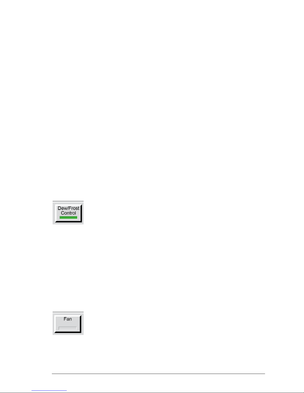
Fan
The SH2 and the SHX measuring head are equipped with a fan to pull a gas
sample through the measuring head. If you are using the SH2 or the SHX
measuring head, press the Fan key on the touch screen to turn the fan on/off. For
further information on the fan refer to section 4.4 ’Measuring Heads’.
8 MBW 473 Manual English V5.0
SH2
SHX
Fan
Fan
MBW 473 Manual English V5.0 9
4 Get to know your 473
4.1 Front Panel
The front panel of the 473 is equipped with a full color touch screen and a keypad for data entry. To
activate a menu option or toggle a function on or off, simply touch the desired key or object directly on
the screen.
When the 473 is turned on, the display will activate within a few seconds. A sample display configuration is shown below. The display configuration can be customized, so your display may look different.
The use and the functions of the display are described in the next chapter.
Menu
Keys
Status
Line
Fixed
Function Keys
Data
Lines
Keypad
10 MBW 473 Manual English V5.0
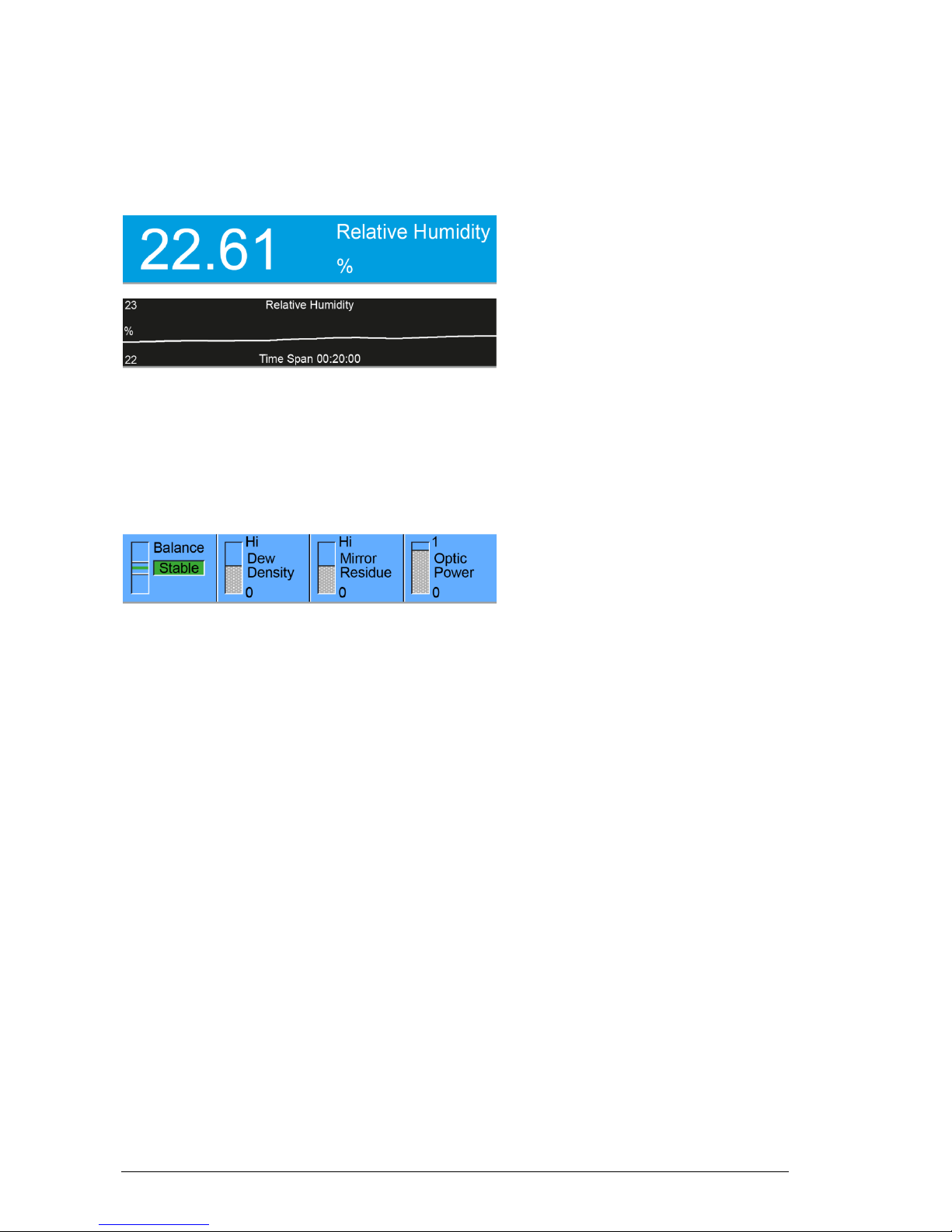
Data Lines
The first three lines of the display show a numeric or graphic representation of the measured data. We
will refer to these first three lines as Data Lines.
If numeric, a data line contains the value
to the left, with the parameter description
and units to the right.
If graphic, a data line shows a simple
graph of data over time.
Data can be displayed in different parameters and units either numerically or graphically. Please refer
to section 5, ‘System Configuration’ to learn how to configure your preferences.
Status Line
Balance
Although it is directly obtained from the intensity of the mirror’s reflected light signal, balance is effectively the first derivative of the dew thickness measurement. It indicates the rate of growth or reduction
of the condensation layer on the mirror. While the dew or frost layer on the mirror surface is growing,
the indicator will be above center. The faster the layer is growing, the higher the indication. Conversely, when the layer on the mirror surface is evaporating, the indicator will be below center. The faster it
disappears, the lower the indication. When the indicator is in the center, the thickness of the dew or
frost layer is neither growing nor evaporating, and the layer on the mirror surface is in equilibrium with
the sample gas. In this center position of the indicator, there is no net exchange of water vapor between the sample gas and the mirror surface. If the humidity of the gas sample is homogeneous and
of low enough variability for the control system to sense a steady value, the Balance indicator will
show a green Stable message, accompanied by a few short beeps.
Density
The Density Indicator graphically depicts the approximate thickness of the dew or frost layer on the
mirror surface. The 473 can automatically differentiate between dew and frost layers and the indicator
will display the current condensation state. The label in the density indicator will change from Layer
Density (when the state of the layer is uncertain) to either Dew Density or Frost Density (when either dew or frost is being measured). For more information regarding Dew/Frost point determination
see section ‘Dew / Frost Control’ on page 30.
Near the bottom of the display is the Status Line. The Status Line displays
Balance, Density, Contamination, and
Optic Power.
MBW 473 Manual English V5.0 11
Mirror Residue
The Mirror Residue Indicator graphically shows the amount of mirror contamination that was detected
during the last mirror check. If the bar covers more than a quarter of the space, we recommend that
you clean the mirror.
Optic Power
The optic power indicates the aging of the LED. When the instrument is used at higher measuring
head temperatures, the LED will age more quickly. When new, the optic condition bar graph will show
as ‘full’. When the indication starts to decrease, it provides the user with advanced notification that the
LED of the optical module may need service or replacement.
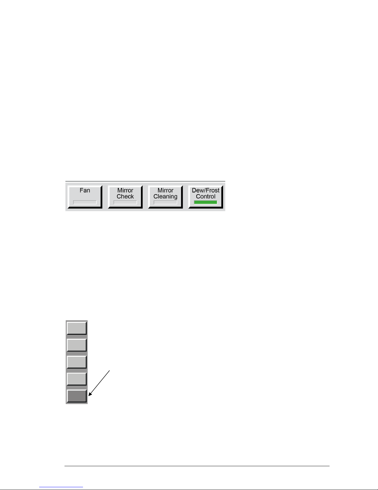
Fixed Function Keys
Menu Keys and Navigation
The menu selection is circular. Once you go past the last menu, the first one will appears again and
the process starts over. You can use the ± key on the keypad to move backward through the menus.
Use the Enter key to exit the menu.
The bottom line of the display
contains a row of fixed function
keys. These keys are used to
start and stop the gas flow fan
(only for SH2 and SHX), initiate
a mirror check, initiate mirror
cleaning, and switch dew/frost
control on or off. For further
information on the fan see
section 4.4, for the other
funcitons see section 5.4.
On the right hand side of the display there is a column of
menu keys. The bottom, dark gray key changes the current menu by cycling to the next menu. Each of the light
gray keys changes their label and function based on the
menu that is currently selected.
Use the dark grey
key on the bottom
(menu selection key)
to move between
menus.

12 MBW 473 Manual English V5.0
4.2 Touch Screen
The 473 dew point mirror is operated using the touch screen. To make a menu selection or switch
functions on or off, touch the screen where appropriate with your finger or a stylus. Never use sharp
objects, as damage may occur.
Before using the 473 for the first time or when several users operate this unit, the touch screen can be
calibrated to suit the user. The procedure is described in chapter 8.1 ‘Calibrate the Touch Screen’ on
page 55.
MBW 473 Manual English V5.0 13
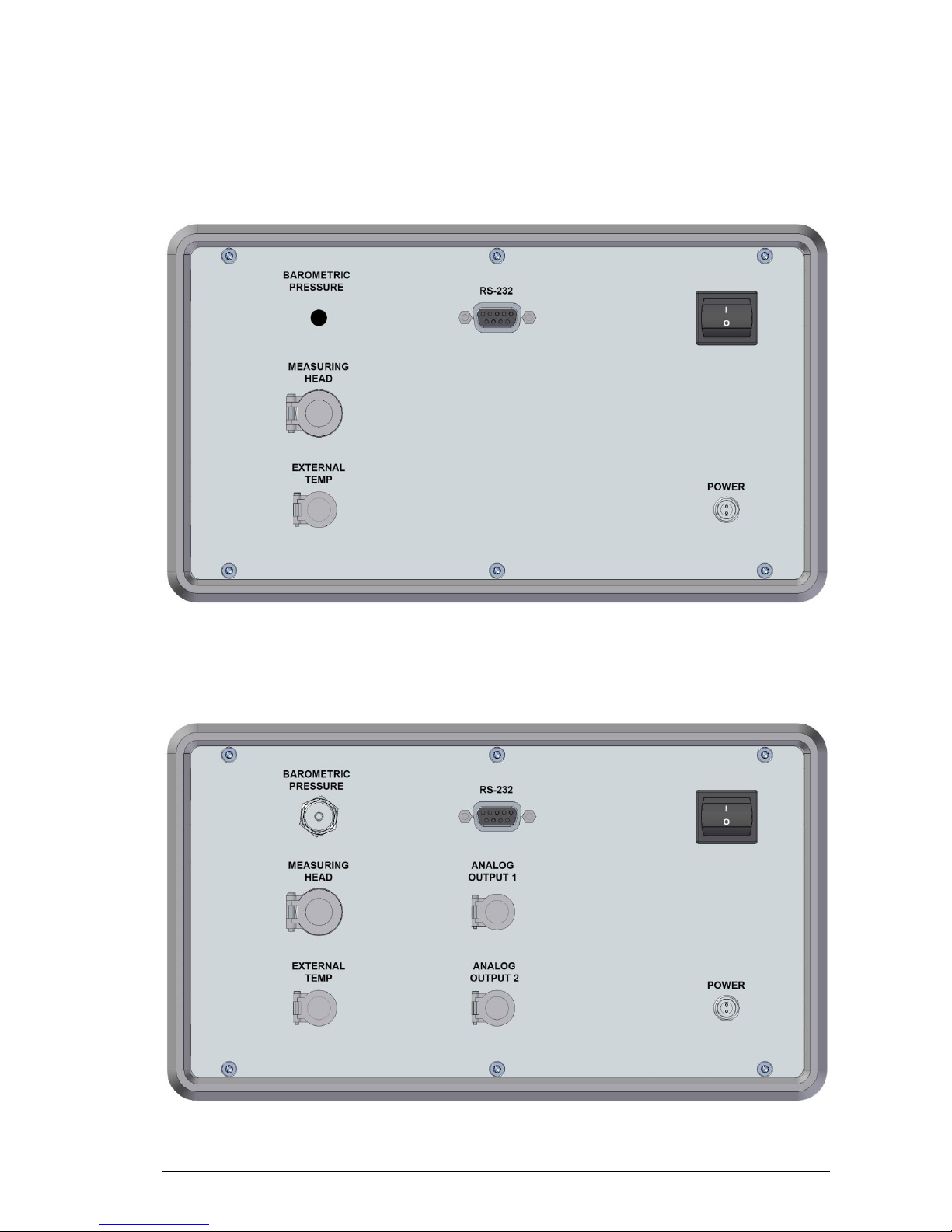
4.3 Back Panel
Without Options
With Barometric Pressure and Analog Output Options

14 MBW 473 Manual English V5.0
Power Switch
The main power switch is on the back panel above the power connection. The external power supply
has a built-in fuse and will automatically switch off in case of overload. To restart power, the main
power switch must be switched off and on again.
Power Supply
The output of the supplied external 24 VDC power supply is connected to the power connection on the
instrument back panel. The supported input voltage for the power supply is 100-120 VAC / 200-240
VAC at 50 to 60Hz.
RS-232
The RS-232 port can be used to connect the 473 to a desktop or laptop computer. The necessary 9pin RS-232 (serial) extender cable is a common accessory and can easily be obtained at any computer store.
Measuring Head Connection
The 473 can be ordered with different types of measuring heads; the RP2, SH2, SH3 and SHX. These
measuring heads are connected to the back panel of the corresponding 473 display unit. The 473RP2, SH2 and SH3 are supplied with a 19-pin measuring head cable, while the 473-SHX is supplied
with a 30-pin measuring head cable.
Internal Barometric Pressure Sensor
As an option you can order an internal barometric pressure sensor to measure ambient pressure. To
measure chamber pressure or to calibrate the sensor, connect a 3 mm tube with a Swagelok fitting to
the pressure sensor port on the back panel.
Optional Analog Outputs
The 473 can be ordered with two optional analog outputs which are independently configurable. For
each of the analog outputs, you can choose which parameter to transmit and scale its range. Please
refer to section 5.7 ‘Configuration of Optional Analog Outputs‘ on page 37 to learn how to configure
the analog outputs.
MBW 473 Manual English V5.0 15
If the instrument is ordered with the optional analog outputs, two 4-pin LEMO connectors (Part Number: FGG.1B.304.CLAD52 www.lemo.com) will be supplied with the instrument. These can be used to
make up a custom cable for your installation.
When the 4-pin LEMO connector is properly assembled, the red
dot of the connector housing should be between pin 1 and 4.
The 473 allows both a voltage and a current output signal. As shown in the illustration above, pins 1 and
2 supply the voltage signal (V), and pins 3 and 4 supply the current signal (I). Inside the instrument, the
output signal is connected to a D/A converter and then split into a voltage and a current signal. Therefore, you may use either a volt or current meter to receive the analog signal. The maximum voltage output range is -10…+10 V. See the following table to identify the corresponding current signal.
Voltage
[V]
Current
[mA]
+10
20 2 4 0 0
-10
N/A
Pin
Signal
Position
Description
1
+V
When viewing the solder tabs of a
disassembled 4-pin LEMO connector,
pin 1 is usually identified with a full or
partial circle drawn around it. Pin 4
should have no identifier. When wiring
the cable, note that the pin numbering
of the socket in the back panel of the
instrument starts at the top left (pin 1)
and goes counter-clockwise (as
viewed from the rear of the unit).
2
-V
3
+I
4
-I
The red dot is between pin 1 and 4

16 MBW 473 Manual English V5.0
External Temperature Probe
The external temperature probe is used to measure the temperature of the environment that is being
measured. To obtain certain humidity parameters, such as %rh, an external temperature measurement is necessary. External temperature measurements are not required for dew or frost point measurements.
• The SH2 is supplied with a Ø2 x 100 mm PRT temperature probe. The probe can be connect-
ed to the 473 in the following ways:
1. Use the supplied 4-pin 0.5 m cable to connect the probe to the measuring head.
2. Use the supplied 5-pin 3 m cable to connect the probe to the back panel of the instrument.
• The RP2 is supplied with a Ø3 x 30 mm PRT temperature probe. The probe can be connected
to the 473 in the following ways:
1. Plug the temperature probe directly into the connector on the top of the RP2
measuring head.
2. Use the supplied 4-pin 0.5 m cable to connect the probe to the measuring head.
3. Use the supplied 5-pin 3 m cable to connect the probe directly to the back panel
of the instrument.
• The SHX is supplied with a Ø3 x 30 mm PRT temperature probe. The probe can be connected
to the 473 in the following way:
1. Use the supplied 4-pin 1 m cable to connect the probe to the measuring head.
• The SH3 is not supplied with a temperature probe as standard, but where one has been speci-
fied it is connected directly to the back panel of the 473 External Temp connector.
Use your own External Temperature Sensor
The External Temperature plug on the back panel is used for the connection of an external temperature probe. External temperature measurements are required if certain humidity parameters, such as
%RH, are to be computed. External temperature measurements are not required for dew or frost point
measurements.
If you wish to make your own thermometer cable, the 473 requires a 5 pin LEMO connector (www.lemo.ch), part number FGG
1B 305 CLAD 52.
Red Dot aligns with Pin 1
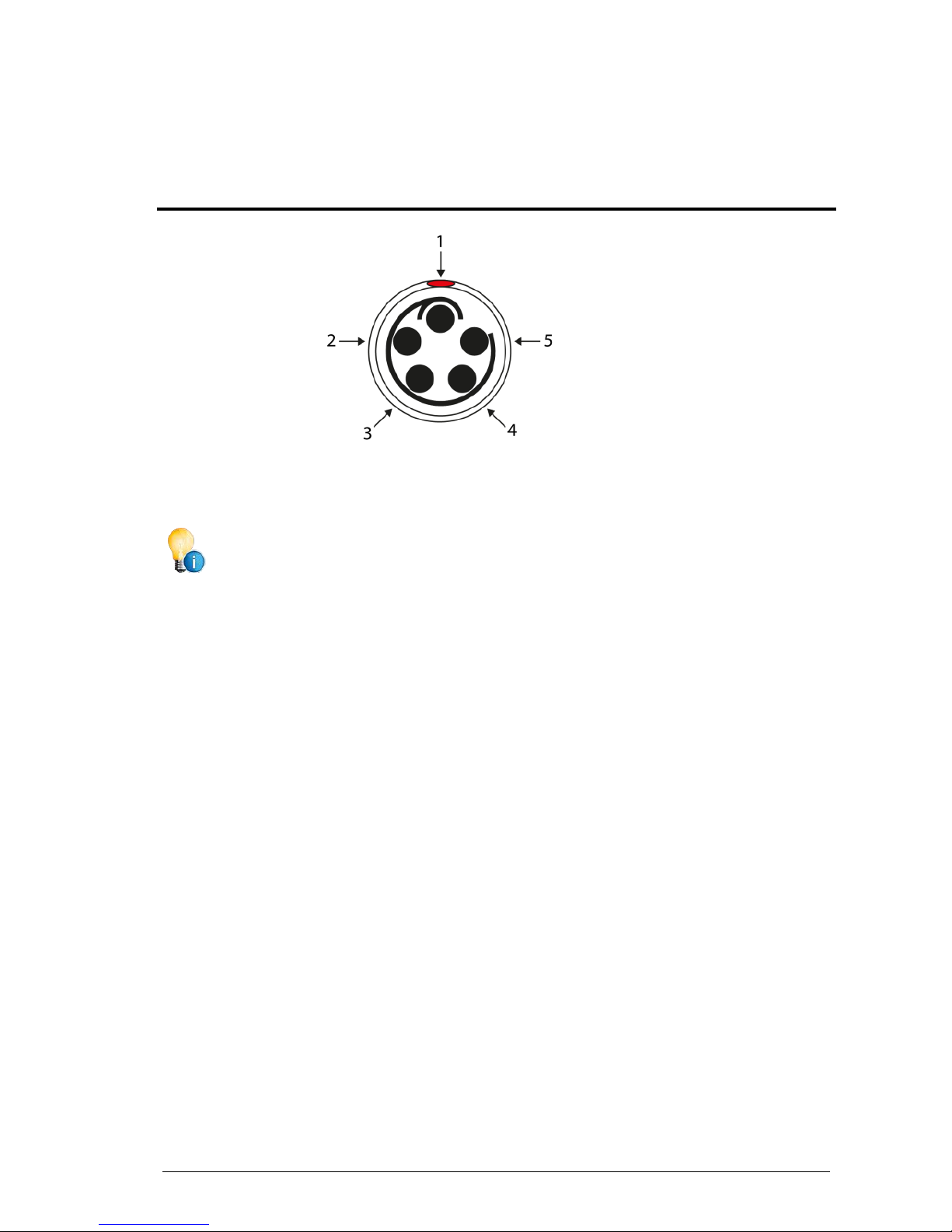
MBW 473 Manual English V5.0 17
After identifying pin 1, follow the line counter-clockwise from pin 1 to all other pins in succession. Wire
the cable according to the following scheme:
When the 5-pin LEMO connector is properly assembled, the red dot of the connector housing
is located directly above pin 1.
Pin
Signal
Position
Description
1
Shield
When viewing the solder tabs of a
disassembled 5-pin LEMO connector,
pin 1 is usually identified with a full or
partial circle drawn around it. Pin 5
should have no identifier. When wiring
the cable, note that the pin numbering
of the socket in the back panel of the
instrument starts at the top left (pin 1)
and goes counter-clockwise (as
viewed from the rear of the unit).
2
+I 3 +V
4
-V
5
-I
 Loading...