

Page 1
Page 2

ALEXXA SERIES
MB QUART IN-CEILING / IN-WALL SPEAKER INSTALLATION INSTRUCTIONS
Thank you for purchasing the MB QUART In-Ceiling / In-Wall speaker system.
To ensure proper installation and operation of the speakers, please follow the manual carefully
and thoroughly.
- Be sure to follow the directions carefully and in the order provided below.
- Do not discard the manual. You will need this for future removal and installation.
- Be sure to adhere to all of the safety and caution tips through out the manual.
- Do not install or operate the speakers near water.
- During the installation, be sure to avoid in-wall and in-ceiling heater/AC ducts, electrical
power lines, plumbing and fire retardant insulation.
- Avoid direct exposure to heat producing sources such as heat ducts, and exhaust vents.
- Do not alter the physical elements of the assembly such as the enclosure, speaker grille or
electrical contact points.
- Route speaker wires away from heat producing sources, moving parts and exposure to water.
- Use a clean dry cloth to clean the speakers when necessary.
- Refer all service to a qualified authorized service center.
Minimum Tool Required Material Supplied
- Wire Strippers - Grille Removal Tool
- Carpenters Level - Speaker Cut-Out Template
- # 2 Phillips Screwdriver - Paint Shield
- Flat Blade Screwdriver - Owner / Install manual
- Electronic Stud Finder
- Drywall Hand Saw
- Miniature Flat Blade Screwdriver for Point Source Speakers
SPEAKER PLACEMENT (ALX2PS / ALX3PS / ALX5.25IC / ALX6.5IC / ALX6.5IC DM / ALX8.0IC)
These speakers are designed to operate in a standard drywall or suspended acoustical panel ceiling.
The speaker enclosure allows for different mounting depths that may be encountered in different ceiling
applications.
Although the speakers sound best when the back section of the speaker is left in tact.
The back section of the speaker can be removed to lessen the over all mounting height if needed.
Some building codes may require that the back enclosure half be removed so please check with your
local building codes.
When mounting to a drywall ceiling, be sure the drywall is at least 3/8” thick.
If you are mounting the speakers to typical acoustical suspended ceiling panels, you will need to
reinforce the acoustical panel with ½” plywood to ensure the speaker does not cause the acoustical
panel to sag over time.
1. Choose mounting locations that are an equal distance left and right of the listening area as shown
in DIAGRAM 1.
2. Use the speaker cut-out template supplied to mark your speaker hole locations.
(Be sure there is clearance behind the area you have chosen for the speaker. Avoid electrical wiring,
plumbing, moving parts, air ducts and Fire Stops.
1
Page 3
3. Use a drywall saw or other appropriate tool to carefully cut out the speaker holes. The cut-out is the
exact size required for the speaker. You also can go as much as 1/4” over this size as “Mistake Room”.
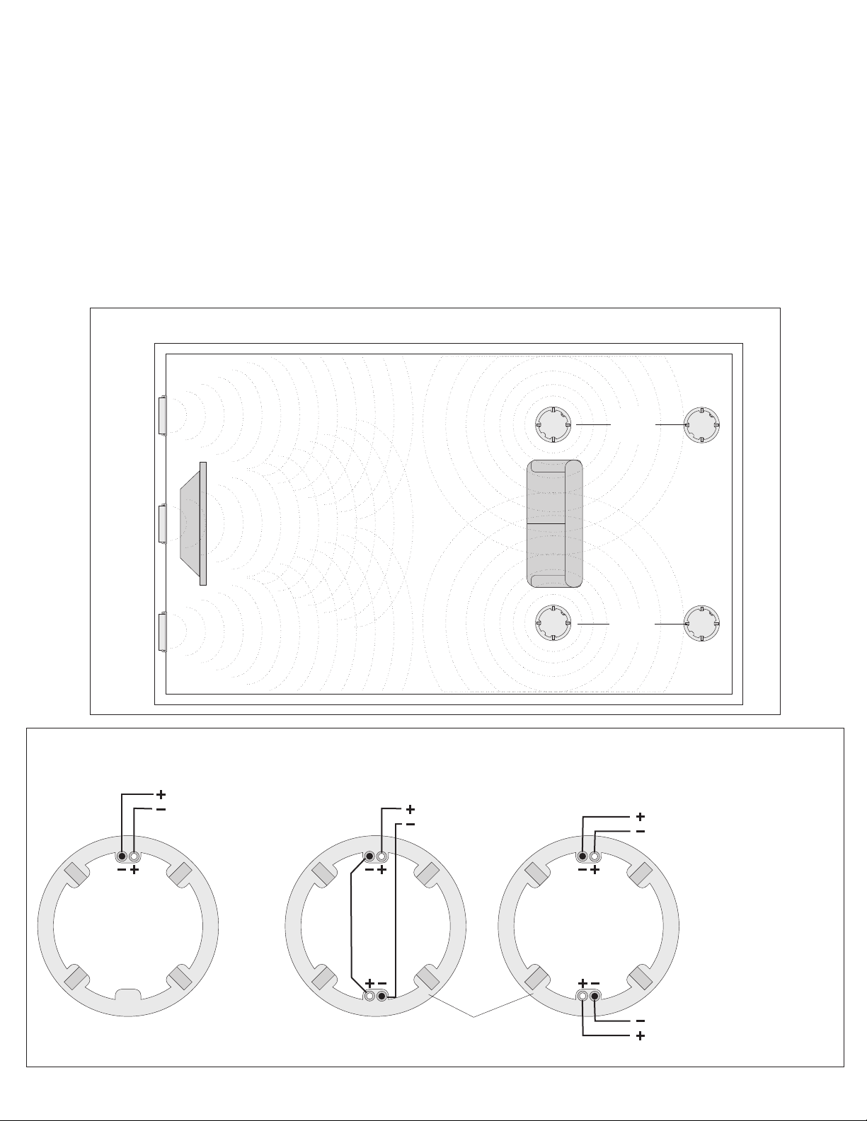
4. Connect the speaker wires (18 gauge wire not supplied) to the speakers as shown in DIAGRAM 2.
(Be sure to get the + and - polarity correct)
5. Place the speaker into the speaker opening and using a # 2 phillips screw driver, turn the Dog-Ear
fastening screws clockwise (be sure to support the weight of the speaker until all Doq-Ear screws
are securely tightened).
The Dog-Ear Clamps will rotate away from the speaker enclosure and begin to tighten against the
mounting surface to secure the speaker as shown in DIAGRAM 3.
6. Carefully route the speaker wires to the amplifier or other power source. Be sure to avoid moving parts,
heat producing items and water exposure.
DIAGRAM 1
RIGHT
FRONT
CENTER
LEFT
FRONT
TV
To amplifier or
surround sound
receiver 8-Ohms
DIAGRAM 2
To amplifier or
surround sound
receiver 8Ohms
RIGHT
REAR
LEFT
REAR
To amplifier or
surround sound
receiver 4-Ohms
SINGLE INPUT SPEAKER
OR
2 CHANNEL INPUT
DUAL-MONO SPEAKER
Use this wiring configuration
to combine left and right audio
channels to power a single
speaker in locations where
right and left speakers are
unsuitable.
To amplifier or
surround sound
receiver 4-Ohms
2
Page 4

Dog Ear
Clamps
(1A)
DIAGRAM 3
Dog Ear
Clamps
(1B)
Dog Ear Screw
HIGH PASS / LOW PASS
SWITCH
Dry Wall or Ceiling Tile
Note: As you turn the Dog-Ear screws clockwise, the
Dog-Ear Clamps will swing out away from the speaker (1A).
Continue to turn the screw and the Dog-Ear Clamps will
Lower down until they reach the mounting surface (1B)
Speaker
connector
+
_
To amplifier or
surround receiver
HP LP
Dog Ear Clamps
Adjustment Screws
MBQUART
+
+
Note: The Point Source speakers
only have 2 Dog-Ear Clamp screws
3
Page 5

IN-WALL SPEAKER PLACEMENT (ALX5.25IW / ALX6.5IW / ALX8.0IW)
These speakers are designed to operate in a standard drywall or wood paneling type wall.
The In-Wall speakers may also be used for front left and right main speakers or even a center channel.
You can mount the speakers in a vertical or horizontal position depending on the limitations of the wall.
1. Choose mounting locations that are an equal distance left and right of the listening area as shown
in DIAGRAM 4.
2. Use the speaker cut-out template supplied to mark your hole locations.
(Be sure there is clearance behind the area you have chosen for the speaker. Avoid electrical wiring,
plumbing, moving parts, air ducts and Fire Stops.
3. Use a drywall saw or other appropriate tool to carefully cut out the speaker holes. The cut-out is the
exact size required for the speaker. You also can go as much as 1/4” over this size as “Mistake Room”.
4. Connect the speaker wires (18 gauge wire not supplied) to the speakers as shown in DIAGRAM 5.
(Be sure to get the + and - polarity correct)
5. Place the speaker into the speaker opening and using a # 2 phillips screw driver, turn the Dog-Ear
fastening screws clockwise (be sure to support the weight of the speaker until all Doq-Ear screws
are securely tightened).
The Doq-Ear Clamps will rotate away from the speaker enclosure and begin to tighten against the
mounting surface to secure the speaker as shown in DIAGRAM 6.
6. Carefully route the speaker wires to the amplifier or other power source. Be sure to avoid moving parts,
heat producing items and water exposure.
Note: To ensure your total surround sound experience, be sure to consider the SW10 and SW12
powered subwoofer system which will provide heart pounding bass to your favorite action movies.
For the ultimate in Hi Fidelity sound quality, check out the MB QUART 5.1 speaker systems (tower
speakers, center channel and book shelf speakers) in several classic and modern finishes.
RIGHT
FRONT
CENTER
LEFT
FRONT
DIAGRAM 4
RIGHT
REAR
5.1 or 7.1
System
LEFT
REAR
4
Page 6

DIAGRAM 6
DIAGRAM 5
To amplifier or
surround sound
receiver 8-Ohms
Drywall
(1B)
Dog Ear
Clamp
Note: As you turn the Dog-Ear screws clockwise, the
Dog-Ear Clamps will swing out away from the speaker (1A).
Continue to turn the screw and the Dog-Ear Clampss will
Lower down until they reach the mounting surface (1B)
Dog Ear
Clamp
(1A)
5
Dog Ear Screw
Page 7

ADDITIONAL INSTALLATION AND OPERATIONAL INFORMATION
- If you do not have the installation cut-out template, the cut-out dimensions are also located on the
speaker label located on the side of the speaker. You can also down load the template by going to our web
site at: www.maxxsonics.com
-
- The speaker trim bezels and grilles can also be spray painted.
There is a paint shield located in the speaker kit to prevent from getting paint on the speaker cone.
Tip: Do not use roll-on paint because it will fill-in the holes in the grille which will dramatically effect
the sound quality.
Be sure to paint the grille separate from the speaker and do not re-install the grille until the paint
has dried.
- You may order additional parts such as Dog-Ear Clamps, Grilles, Grille removal tools by contacting
Maxxsonics at: www.maxxsonics.com
In-Ceiling
Speaker
In-Wall Speaker
Mid Range Speaker
Angled Baffle Adjustment
The Alexxa series speaker feature an angled baffle
design which positions the speaker on a 30% angle
to the speaker enclosure. This allows you to rotate the
speaker enclosure so that the speaker cone is facing
towards the listening area as shown on Diagram 4.
Tweeter Element
Or
Or
This is ideal for cathedral or pitched ceilings or walls
do not permit the ideal mounting locations.
Or Or
Mid Range Speaker
Tweeter Angle Adjustment
The tweeter element can be swivelled to allow
you to aim or point the tweeter towards the
listening area as shown above. In the event
the mid bass speaker can not be aimed towards
Tweeter Angle Adjustment
The tweeter element can be swivelled to allow
you to aim or point the tweeter towards the
listening area as shown above. In the event
the mid bass speaker can not be aimed towards
ALEXXA SPEAKER SPECIFICATIONS
MODEL POWER RATING IMPEDANCE CUT-OUT
ALX2PS 5 - 20 WATTS 8-Ohms / 6-Ohms nom. 3.9” / 99mm Diameter
ALX3PS 5 - 30 WATTS 8-Ohms / 6-Ohms nom. 4.35” / 111 mm Diameter
ALX5.25IC 80 WATTS 8-Ohms / 6-Ohms nom. 8.9” / 227mm Diameter
ALX6.5IC 100 WATTS 8-Ohms / 6-Ohms nom 10.25” / 260mm Diameter
ALX6.5IC DM 100 WATTS 4+4-Ohms / 3+3-Ohms nom. 10.25” / 260mm Diameter
ALX8.0IC 120 WATTS 8-Ohms / 6-Ohms nom. 12.4” / 315mm Diameter
ALX5.25IW 80 WATTS 8-Ohms / 6-Ohms nom. W: 7.26” / 184.5mm x L: 14.1” / 358mm
ALX6.5IW 100 WATTS 8-Ohms / 6-Ohms nom. W: 7.9” / 200.5mm x L: 14.1” / 358mm
ALX8.0IW 120 WATTS 8-Ohms / 6-Ohms nom. W: 10.3” / 262mm x L: 20.2” / 513mm
FEATURES SUBJECT TO CHANGE WITH OUT NOTICE
6
Page 8

5-Year Limited Warranty
Domestic Warranty ( U.S.A. AND CANADA ONLY )
The MB Quart Home Audio Speaker warranty for In-Wall and In-Ceiling Speakers is valid only for consumers in
the United States or Canada.
MB QUART, Maxxsonics Europe GmHb ("MB QUART") warrants this product to be free from defects in
workmanship and materials (subject to the below terms) for a period of ( five) 5-years from the date of original
purchase to the original purchaser. During the Warranty period, MB QUART will repair or replace (at MB
QUART’s sole option) this product or any defective parts. To obtain Warranty service, please contact the MB
QUART authorized dealer from which you purchased this product. If your authorized MB Quart Dealer is not
equipped to perform the repair of your MB QUART product, it can be returned, freight paid, to MB QUART for
repair. Please call MB QUART at ( 847-540-7700 ) for instructions. Only ship this product in its original
packaging or packaging with an equal degree of protection. All damages resulting from insufficient packing are
the sole responsibility of the products owner.
Proof of purchase in the form of a Bill Of Sale or receipted invoice, issued by an authorized MB Quart dealer is
always required for any and all warranty related services.
This receipt and or Bill of Sale which is evidence that this genuine MB Quart product is within the manufacturer’s
warranty period. Said evidence must be presented or included to obtain any warranty service. This warranty is
invalidated when and if the factory-applied serial number has been altered or removed from this product or this
product was not purchased from a MB QUART authorized dealer.
Call Maxxsonics at 847-540-7700 to confirm your purchase was from an MB QUART authorized dealer.
Be prepared to supply the unaltered serial number when requested. Return instructions and a coded Return
Authorization number will be given to the purchaser. Following these steps prior to returning a product to MB
Quart for warranty prevents your package from being refused upon delivery.
Valid only to the original purchaser, this warranty automatically terminates before expiration if the
product is sold or otherwise transferred to another party.
This warranty does not cover product sold AS IS or when sold WITH ALL FAULTS. This warranty does not
cover abuse, damage, cosmetic damage or damage due to misuse, accidents, negligence, Acts of God,
Commercial Use, or modification of, or to any part of the product. This warranty does not cover damage due to
improper operation, maintenance or installation, or attempted repair by anyone other than MB QUART or a MB
QUART dealer which is authorized to do MB QUART warranty work. Unauthorized repairs void this warranty.
THE EXCLUSIVE REMEDY OF THE CONSUMER PROVIDED UNDER THIS WARRANTY IS REPAIRS OR
REPLACEMENTS OF PRODUCT.
MB QUART SHALL NOT BE LIABLE FOR ANY INCIDENTAL OR CONSEQUENTIAL DAMAGES FOR
BREACH OF ANY EXPRESS OR IMPLIED WARRANTY ON THIS PRODUCT. EXCEPT TO THE EXTENT
PROHIBITED BY LAW.
THIS WARRANTY IS EXCLUSIVE AND IN LIEU OF ALL OTHER IMPLIED AND EXPRESS WARRANTIES
WHATSOEVER, INCLUDING BUT NOT LIMITED TO, THE WARRANTY OF FITNESS AND
MERCHANTABILITY FOR A PRACTICAL PURPOSE.
Some states do not allow the exclusion or limitation of incidental or consequential damages or implied
warranties so the above exclusions may not apply to you. This warranty gives you specific legal rights, and you
may have other rights, which vary from state to state.
WARRANTY OUTSIDE THE UNITED STATES & CANADA.
The warranty on this product if it is sold to a consumer outside of the United States or Canada shall comply with
applicable law and shall be the sole responsibility of the distributor that supplied this product. To obtain any
applicable warranty service, please contact the dealer from which you purchased this product, or the distributor
that supplied this product. Products purchased outside the United States are not to be returned to any
Maxxsonics Dealer or Maxxsonics facility within the United States under any circumstances.
7
Page 9

 Loading...