

Page 1

CREASE MATIC
AUTO 50
Operators Manual
Page 2

Contents
Contents ……………………………………………………………………….. 2
Introduction ……………………………………………………………………. 3
Machine Components …………………………………………………………. 4
Setting Side Lays ………………………………………………………………. 5
Setting Outfeed Tray …………………………………………………………… 7
Changing Crease Matrix ……………………………………………………….. 8
Choke Adjustment and Rotating Cylinder …………………………………….. 9
Thin Gauge Paper Setting ……………………………………………………… 10
Heavy Gauge Paper……………………………………………………………... 10
Feed Gate Adjustment…………………………………………………………... 11
Horizontal Adjustment………………………………………………………….. 11
Vertical Adjustment…………………………………………………………….. 12
Perforation Wheels……………………………………………………………… 13
Top Shaft Alterations……………………………………………………………. 14
Bottom Shaft Alterations………………………………………………………... 15
Compressor/Vacuum Controls………………………………………………….. 16
Touch Screen Pages - Login Page…………………………………………….… 17
Run Page………………………………………………………………………… 18
Receipt Edit Page………………………………………………………………... 19
Crease Setting page 01……………………………………………..……………. 20
Crease Setting page 2-4……………………………………………………….…. 21
Service Menu ……………………………………………………………………. 22
Status Screen……………………………………………………………………… 23
Engineers Settings………………………………………………………………... 24
Factory Settings………………………………………………………………….. 25
Absolute and Incremental Programming…………………………………………. 26
Login Process…………………………………………………………………….. 27
Auto 50 Problem Solving………………………………………………………… 28
MBM Corporation
Michael Business Machines
3134 Industry Drive
North Charleston
South Carolina 29418
Customer Service - Tel: (800) 223 2508
Fax: (803) 552 2974
Parts & Service - Tel: (800) 223 2508
Fax: (803) 760 3814
Auto50-ops-touch screen usa 4/3/2013
2
Page 3

Introduction
Crease Matic Auto 50
Designed and manufactured in the U.K., the new Crease Matic Auto 50 is a fully
programmable high speed card creaser. Documents are suction fed and creased at up to
7000 sheets per hour. It is possible to crease Digital and Litho printed card, removing
cracking that may occur at the folding stage.
The CM Auto 50 is capable of accommodating stock from CD-SRA2 (500x700mm), with
a capability to program a maximum of 29 creases per sheet anywhere along its length.
A maximum of 99 different jobs can be programmed and saved to the machines internal
memory, making the selection and recall of common jobs quick and easy.
Jobs are programmed in Absolute mode. All crease positions are measured from the
leading edge and entered directly. Incremental mode may be used to make image shift
adjustments with one alteration.
The machine is supplied with rotary perforation that is adjustable across the width of the
document, and four widths of slide-out and turn crease matrix as standard.
Auto50-ops-touch screen usa 4/3/2013
3
Page 4

Machine Components
When installing the machine the supplied power cable should be plugged into the
switched power socket on the machine and then to the power supply socket. Switch the
machine on and the control screen will initialize. The compressor/vacuum unit has a
separate on/off switch located under the Choke Control Wheel. This allows the unit to be
switched off when not in use.
Auto50-ops-touch screen usa 4/3/2013
4
Page 5
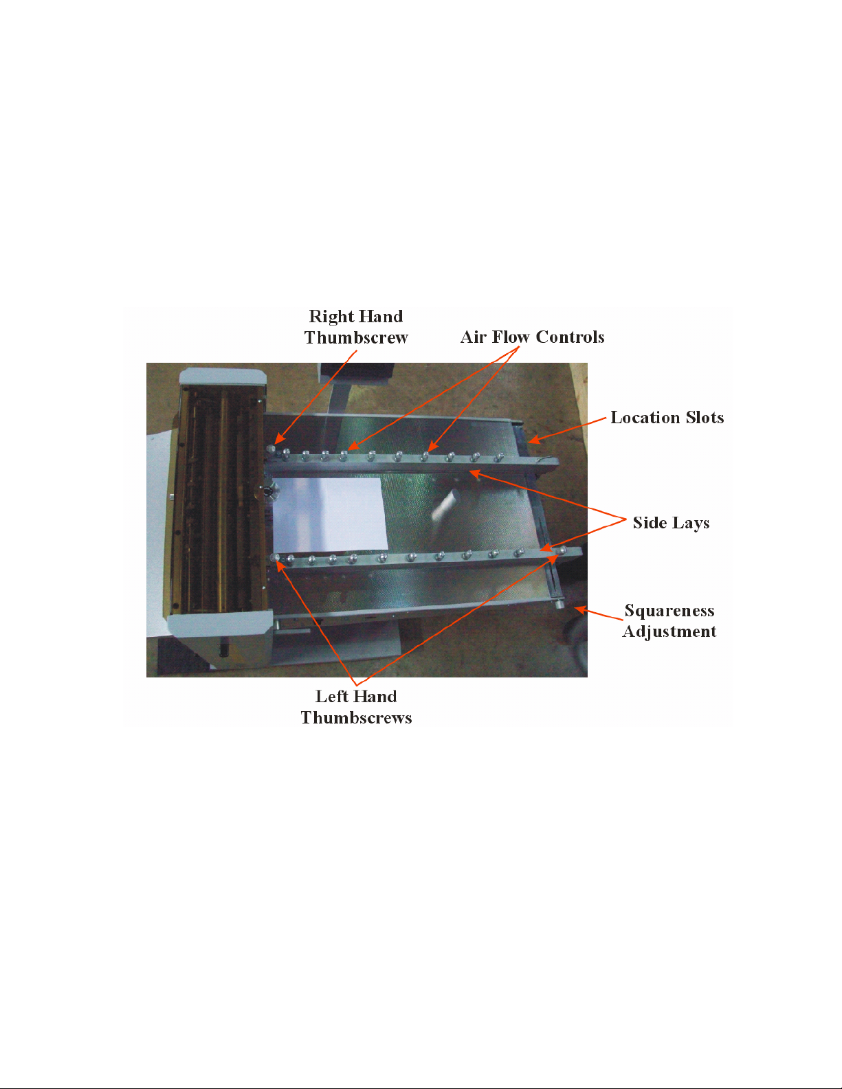
Setting Side Lays
There are two side lays on the machine which sit at each side of the paper on the infeed
section. Their purpose is to guide the paper under the feed gate and into the feed rolls
accurately, to ensure a square crease is made across the document. They also supply air to
the underside of the paper stack, by way of thin slots, in order to make the paper “float”
before the bottom sheet is vacuum fed away under the feed gate.
On the CM Auto 50 there is also the capability to adjust the lays out of squareness to
accommodate for non square crease lines, although this adjustment is minimal.
Firstly, ensure that the squareness adjustment is set to its central position by aligning the
two marks on the machine bed.
The right hand side lay has four location positions. By releasing the thumbscrews at the
feed gate end, the lay may be extracted from one slot and repositioned in another, using
the thumbscrew to secure it. This position must be selected with the paper size being fed
in mind, in order to keep the feed gate as central as possible to the paper centre line.
Once the right hand lay is in position, loosen the two thumbscrews at either end of the left
hand side lay and with a single sheet in the machine, push it across to the correct width of
document. The lays should not pinch the document and the paper must sit on top of the
protruding edge at the base of the lay. Secure the thumbscrews when in position.
Auto50-ops-touch screen usa 4/3/2013
5
Page 6
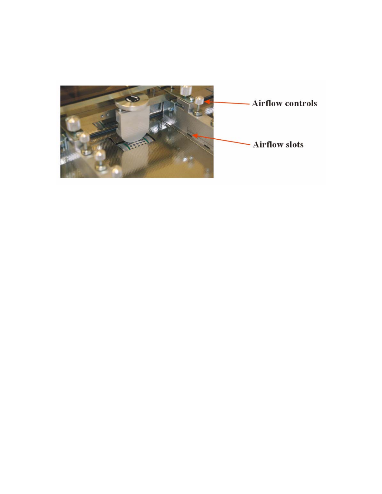
Setting Side Lays cont.
Air flow to the slots is controlled using the thumbscrews running along the top edge of
each lay. By screwing them down (clockwise) all the way the flow of air will be stopped.
This should be done if the document does not cover the slots. Screwing them up will
allow air to pass through the slot. The thumbscrews are fitted with anti-vibration devices,
to prevent the settings from altering during normal operation. After placing the paper
onto the machine, the magnetic backstop should be placed behind the stack to prevent it
from moving.
Auto50-ops-touch screen usa 4/3/2013
6
Page 7
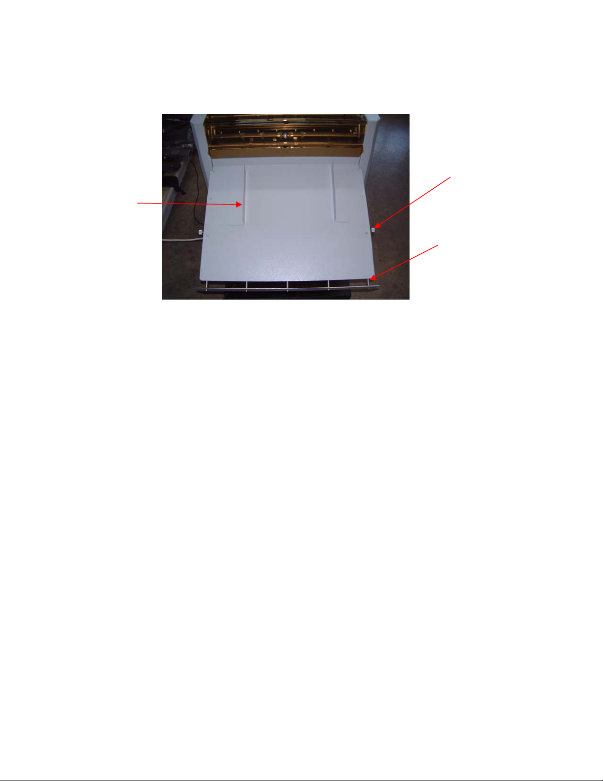
Setting Outfeed Tray
Thumbscrews
Magnetic
Side Lays
Bottom
Stop Plate
The outfeed tray has two thumbscrews , one on each side. By loosening the thumbscrews
the bottom stop plate may be extended to allow larger sheets to be collected without
damage.
The magnetic side plates may be positioned to keep fed documents stacked accurately.
The outfeed tray can be removed in order to adjust the lower perforation wheel shaft.
Auto50-ops-touch screen usa 4/3/2013
7
Page 8
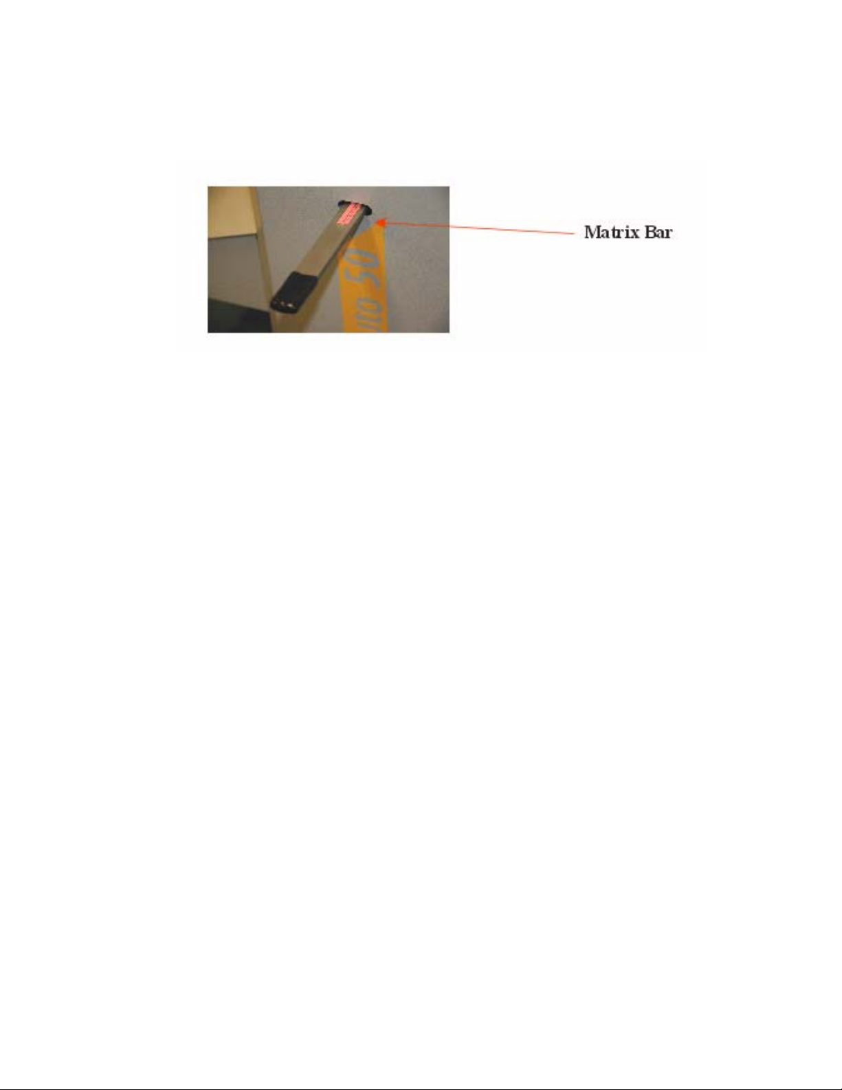
Changing Crease Matrix
The machine is supplied with two crease matrix bars that have different widths of slot on
either side. One of these slots allows the operator to use replaceable self adhesive matrix
bars, the other three may be changed depending on the thickness of the material to be
creased.
The bar must only be changed while the machine is in its rest position with the knife at its
highest point. Withdraw the bar from the slot, turn or replace with the correct size slot,
and slid the bar into the machine until it stops.
Auto50-ops-touch screen usa 4/3/2013
8
Page 9
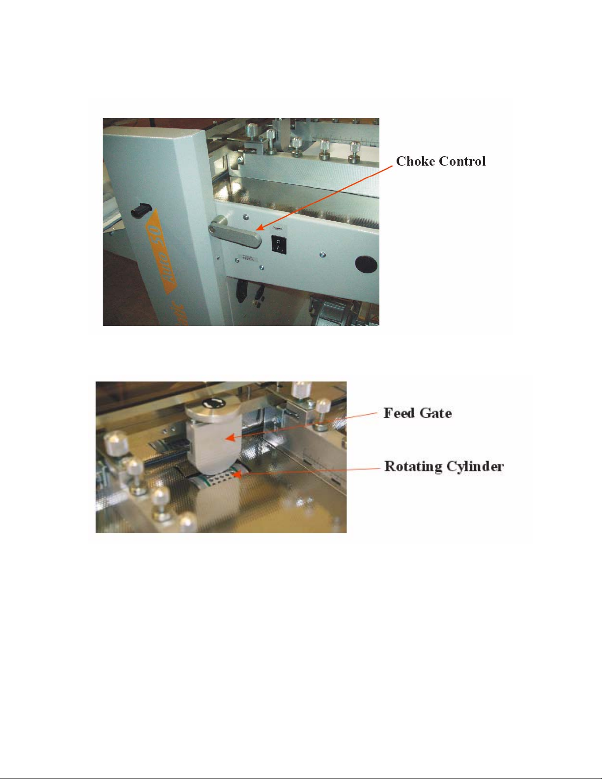
Choke Adjustment and Rotating Cylinder
The choke is used to control the amount of vacuum applied to the front edge of the paper
through the rotating cylinder holes.
The amount of vacuum needed is dependant on the type of paper being fed. Thin gauge
paper, 80gsm to 90gsm will tend to wrap around the cylinder easier than thick gauge
paper, and will need less vacuum to feed.
By rotating the choke control wheel clockwise, more area of slot inside the cylinder is
exposed through the holes and so more of the front edge of the document is sucked onto
the wheel.
Auto50-ops-touch screen usa 4/3/2013
9
Page 10

Thin Gauge Paper Setting.
Rotate the choke adjustment knob anticlockwise until the slot inside the cylinder is tilted
towards the feed gate. This adjustment may be fine tuned during operation.
Feed Gate
Cylinder
Paper
Choke
Heavy Gauge Paper.
Rotate the choke clockwise until the slot is in an upright position.
Feed Gate
Cylinder
Paper
Choke
Auto50-ops-touch screen usa 4/3/2013
10
Page 11

Feed Gate Adjustment
The feed gate is set to allow only one document past at a time. This is achieved by
altering the gap and position of the bottom edge of the gate to the rotating cylinder. There
are two thumbscrew adjustments. One on top, to allow the vertical movement of the gate,
and one under the top cover, to allow horizontal movement. Adjustment of the gate
carried out along with adjustment of the choke.
Horizontal Adjustment
Firstly, set the choke to the correct position for the thickness of document about to be fed.
Then, using the smaller thumbscrew, align the front face of the feed gate to the left hand
edge of the choke slot, seen inside the rotating drum.
Front Face
Auto50-ops-touch screen usa 4/3/2013
11
Page 12

Vertical Adjustment
The vertical adjustment is used to achieve the correct gap between drum and feed gate
dependant on paper thickness being fed.
Place a stack of paper onto the machine feed table. With the machine and compressor
turned on, adjust the vertical thumbscrew until only one document is taken from the base
of the stack at a time.
Auto50-ops-touch screen usa 4/3/2013
12
Page 13

Perforation Wheels
Top Wheel
Control Wheels
Spring
Bottom Wheel
The perforation wheels are located under the top cover of the machine. The outfeed tray
may be lifted clear of the machine in order to gain access to the lower shaft. By altering
the position of the wheels along their shafts, perforations can be made at any point across
the documents width. You can use the perforation wheels without needing to crease the
documents. There are also feed wheels on these shafts, and it may be necessary to alter
their positions to achieve the correct perforation position. To perform perforations away
from the centre of the paper, the order of the feed wheels and perforation wheels on the
shaft must be changed to maintain drive across the width of the document.
Location
Holes
Sprung
Locator
Top Shaft
and Collar
The wheels may be raised or lowered using the sprung locator to the left end of the top
shaft. Two location holes allow easy positioning of the shaft in either the up or down
position. The shaft must be in its up position to make any alterations to the perforation
position. When lowering the top shaft, the perforation wheel must be pulled against the
spring until it is located, so that the wheels are in contact when the spring is released.
Auto50-ops-touch screen usa 4/3/2013
13
Page 14

Top Shaft Alterations
Top Shaft and
Perforation Wheel
The top shaft must be in its raised position to be removed. It is removed by undoing the
grub screw in the collar on the left hand end and sliding the collar to the right and out of
the bush, allowing the end of the shaft to come towards you. It can then be removed from
its location on the right hand side. The components on the shaft can then be loosened,
slide off and repositioned in the desired order.
Note. The perforation wheel is positioned between two drive wheels and is sprung
loaded. This arrangement must stay the same wherever you position the perforation wheel
along the shaft.
All screws should be tightened onto the machined flat so that the shaft is not damaged.
Refitting is the opposite of removing. Locate the right hand end of the shaft in the bush
on the right side of the machine, line up the left hand side and slide the collar into the
bush. Tighten the screw to secure.
Accurate setting of this wheel can only be achieved when a test document is run, and
final adjustments to measurements should be made at this stage.
Auto50-ops-touch screen usa 4/3/2013
14
Page 15

Bottom Shaft Alterations
Collar and
Grub Screw
The bottom shaft can not be removed from the machine but can be slid across to allow
components to be removed and repositioned.
Note. The drive wheels on the bottom shaft must stay in line with the wheels on the top
shaft.
Bottom Shaft
Collar and Gap
Undo the grub screw in the collar on the left hand end of the shaft. Slide the shaft to the
right until there is a big enough gap near the collar to remove the drive wheels.
Reposition the desired components opposite the wheels on the top shaft and tighten in
position. Slide the shaft back into the collar and tighten the grub screw onto the flat.
Accurate adjustments and alignment may be made with the top shaft down.
Auto50-ops-touch screen usa 4/3/2013
15
Page 16

Compressor/Vacuum Controls
Where the compressor/vacuum unit has two controls. The right hand control wheel
increases and decreases the supply of air to the machines side lays. The left hand control
alters the amount of vacuum supplied to the choke. This may need to be decreased when
using light or thin paper.
If the compressor/vacuum unit is not fitted with air flow controls, the volume of air
delivered to the paper stack may be reduced by opening the uncovered air flow controls
in the side lay.
Auto50-ops-touch screen usa 4/3/2013
16
Page 17

Screen Sequence.
Logon Page:
Press the open padlock sign to logon.
Press within the dotted area to proceed to the ‘Recipe Select Page’.
Recipe Select Page:
Press any of the default setups to go to the ‘Run’ page. Default recipes may only be
adjusted from the Run screen Edit button if the user is logged in as ENGR or FACT.
Press RECIPE to manage customer created recipes.
Auto50-ops-touch screen usa 4/3/2013
17
Page 18

Run Page:
Edit: Press to edit the job directly.
Load: Press to load changes from ‘Edit’ to the controller.
Act Sheet: ‘Reset’ will clear the Act Sheet if pressed for 3 seconds.
Set Sheet: Job counter. Press to set max number of pages to be processed.
Speed: Press number to enter speed setting, select speed and press enter.
Auto50-ops-touch screen usa 4/3/2013
18
Page 19

Recipe Edit Page:
Edit: Proceeds to ‘Crease Setting Page 01’ for the recipe selected.
Load: Proceeds to the ‘Run’ screen.
Delete: Deletes the recipe selected.
Create: Create a new recipe. In the recipe pull down menu, a new recipe is created and
named to a default name, for example “r7”. Press this name to change it. Then press
‘Save & Load’. A pop up box will then appear allowing the user to configure the job in
Inches or Millimetres, Incremental or Absolute. ‘Cont..’ will proceed to ‘Crease Setting
Page 01’.
Auto50-ops-touch screen usa 4/3/2013
19
Page 20

Crease Setting Page 01:
Auto50-ops-touch screen usa 4/3/2013
20
Page 21

Crease Setting Pages 2 to 4:
Auto50-ops-touch screen usa 4/3/2013
21
Page 22

Service Menus:
Visibility dependent on login code:
Manager - MNGR (5138)
Engineer - ENGR ()
Factory - FACT ()
Auto50-ops-touch screen usa 4/3/2013
22
Page 23

Status Screen:
Information only.
Auto50-ops-touch screen usa 4/3/2013
23
Page 24

Engineer Settings:
Sheet Tolerance: The length of every sheet passed through the machine is measured for
error detection. Adjust this value to regulate stoppages.
Photo to Knife Offset: Distance from the paper detection photocell to the knife. This
setting can be adjusted to give the correct first crease position from the leading edge of
the paper.
Feed Timeout: Feed distance of paper feed roll before a Paper Jam Error is made. This
may be disabled by the button below.
Default Settings are:
Sheet Tolerance - 50
Photo to Knife offset - 23.5
Feed Timeout - 800
Auto50-ops-touch screen usa 4/3/2013
24
Page 25

Factory Setting:
Default Settings are:
Acceleration - 28000
Deceleration - 40000
KPn - 0.0651
TNn - 16.00
TAUnref - 1.0
TAUiref - 0.2
Trim Factr - -2.0
Min Speed: Roll speed at Speed 0 - 100
Max Speed: Roll speed at Speed 9 - 2400
Auto50-ops-touch screen usa 4/3/2013
25
Page 26

Absolute and Incremental Programming
t
d
The main difference between the two types of programming system is that Absolute
measurements are taken from the leading edge of the document, and Incremental
measurements are taken from the previous crease line.
The machine is not meant to be programmed initially in Incremental mode!
It is intended that the initial program should be entered in Absolute. I.e. all measurements
are taken from the leading edge. Then if an adjustment is required because the print
registration has changed to the leading edge, select “Incremental”, then enter program
mode and any change to any crease position will also affect any following crease
positions by the same amount.
Example.
A document requires three creases, the first is 100mm from the leading edge, the second
is 150mm from the leading edge and the third is 175mm from the leading edge as shown
below.
Front Edge
100mm
s
1
50mm
nd
2
25mm
r
To program this job in Absolute, all of the measurements are taken from the front edge,
1st crease at 100mm
2nd crease at 150mm
3rd crease at 175mm
To program with Incremental measurements, the first distance is taken from the front
edge, the second is taken from the first crease, and the third from the second crease.
st
crease at 100mm
1
nd
2
crease at 50mm
rd
crease at 25mm
3
Auto50-ops-touch screen usa 4/3/2013
26
Page 27

Login Process:
Four login modes are available:
0 User – access to crease positions on all jobs (5)
1 Manager - as above plus access to default speed (8191)
2 Engineer - as above plus access to photocell offset and languages (xxxx)
3 Factory - as above plus access to motor parameters (xxxx)
The LED to the felt of the display indicates the login level.
Access to anything other than crease positions is only available on program 1.
To login:
From start up, press continue at any time to start. If a valid code is not entered, login
defaults to ‘user’.
To login adjust the present digit with the ‘up’ and ’down’ keys, when correct press the
‘right’ key to advance to the next digit. When the last (forth) digit is correct, press the
‘continue’ key.
Auto50-ops-touch screen usa 4/3/2013
27
Page 28

Auto 50 problem solving:
1. ‘Knife error’ or ‘stop’ showing on screen.
1.1. Machine jamming with card
1.2. Knife out of position.
Try a different matrix tool
1.3. Knife pulley loose on motor shaft
2. Knife does not always cycle or behaves erratically:
2.1. Ensure knife flag is aligned with and passes through the slotted photocell.
2.2. With age and use the knife may over run at the end of cycle. Ensure that at the
end of cycle the flag is still obscuring the slotted photocell.
2.3. Check output from photocell. Place positive probe (red) of meter (set to 24v DC
range) on orange at local terminal strip and place other probe (black) on pin 29
(white/red wire) of the green IDC connector. When the photocell beam is broken
(knife flag) the meter should read 5volts, other wise 0volts should be shown.
2.4. Check and change as necessary R4, the knife motor run relay.
2.5. Knife pulley loose on motor shaft
3. Paper feeds through machine without being creased:
3.1. Ensure a crease position is set.
3.2. Check output from photocell. Place positive probe (red) of meter (set to 24v DC
range) on orange at local terminal strip and place other probe (black) on pin 31
(white/blue wire) of the green IDC connector. When the photocell beam is
broken (paper present) the meter should read 5volts, other wise 0volts should be
shown.
4. Feed motor does not run:
4.1. Ensure cover is closed (white/brown wire).
4.2. Ensure catch tray is properly attached.
4.3. Ensure main (large 11 pin relay) is actuated. Contacts are in up position.
4.4. Ensure motor inverter shows green LED (enabled). If LED is red, motor is not
enabled.
Auto50-ops-touch screen usa 4/3/2013
28
Page 29

5. Paper does not feed:
5.1. Ensure compressor is on.
5.2. Ensure side lay are not too tight
5.3. Ensure paper stack is “floating”.
5.4. Check gate position.
5.5. Check throttle position.
5.6. Ensure suction relay (leftmost small relay) has actuated. Relay with grey wire to
right of 11 pin. Contacts are up.
5.7. Ensure suction valve has operated. I.e. solenoid has “pulled in”
5.8. Check setting of solenoid for suction valve. Release valve body cap (two 5mm
set screws) to allow a 1mm gap between the cap and the body. Loosen the the
hex bolts holding the solenoid block to the cover plate. Pull the solenoid block
away from the valve until there is no slack in the system. Tighten hex bolts. Now
tighten set screws in cap. This last action will force the solenoid bolt out of the
solenoid.
From
To Wheel
Compressor
Valve Body
Spring Stop
Auto50-ops-touch screen usa 4/3/2013
Return Spring
29
Page 30

6. Crease position is not accurate.
Set a new job with 1 crease. Turn the air off. Remove stack from feeder. Feed a single
sheet several times through the Creaser. Does the crease line move? If yes:
Side lays set too loose, feed restricted.
6.1.1. Side lays set too tight, page twisting.
Set a new job with 4 creases set at 50, 100, 150 and 200mm. Run 8 pages. Line up the
leading edges together. Are the first creases in line? No:
Feed Gate set too wide, over feeding.
Ensure the job is feeding consistently and not overfeeding.
Line up the first creases together. Are the second, third and forth creases in line?
Check entry roll pressure. Release screws in roll bearings. Ensure roll is free to lift. Feed
two 1” strips of 80gsm (20 lb) paper at extreme ends of roll. Tighten locking screws.
Check tension of 180xl belt on rollers and tighten as necessary.
Auto50-ops-touch screen usa 4/3/2013
30
 Loading...