

Page 1
T09120
INSTALLATION INSTRUCTION MODEL 46
UPGRADING THE MODEL 45 PCB
Before connecting a Model 46 to a Model 45 with machine No. 45033070 or lower, capacitor
C35 on the PCB PL45 need to be replaced.
CAUTION: Always handle the PCB, EEPROM, micro processor etc. in accordance with electro-
static discharge procedures (ESD). The PCB contains components that are sensitive to
ESD damage.
REMOVAL
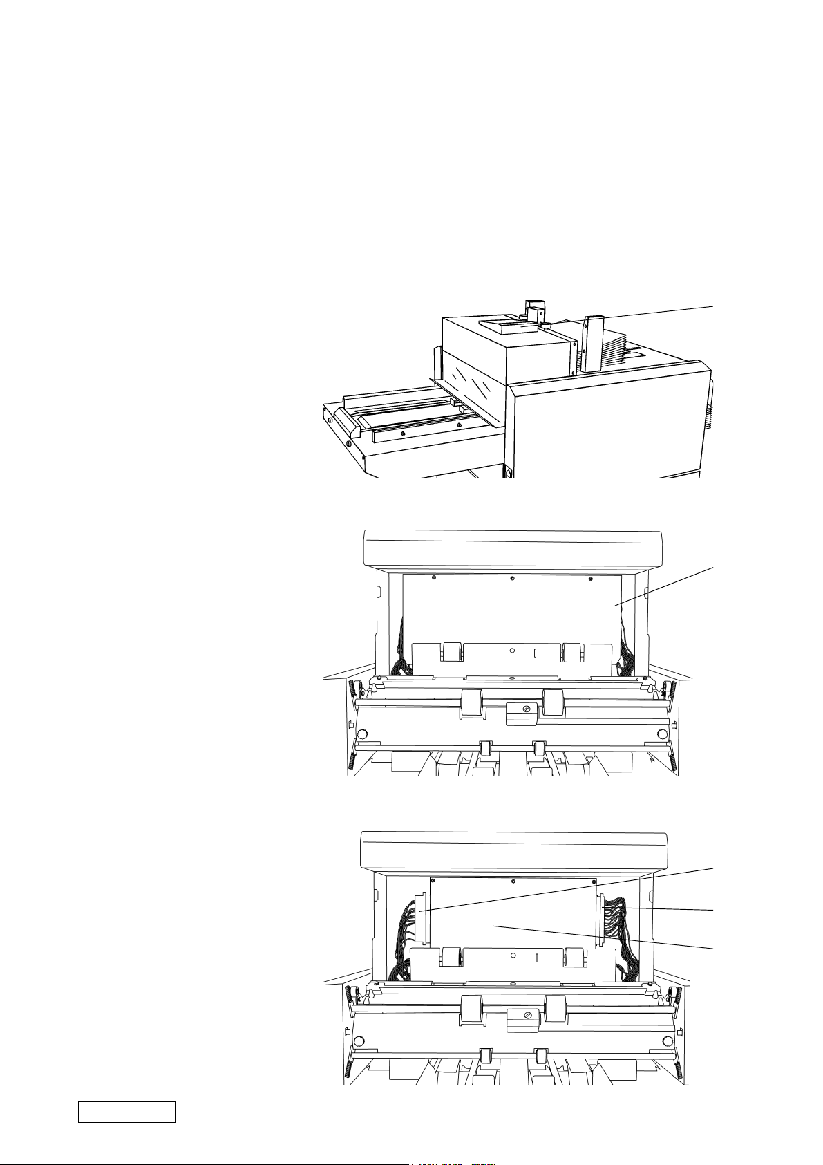
1. Switch off the main power
switch and disconnect the
power cord.
2. Loosen the screw (1) on the
back side of the control panel.
3. Push the control panel towards
the rear side and lift it.
4. Remove the ground wire and
the ribbon cable.
5. Slide the envelope feeding
table open.
6. Open the envelope feeding
cover.
7. Remove the five screws
holding the PCB cover plate
(2).
1
2
8. Remove the PCB cover plate.
9. Remove the plugs P1 (3) and
P2 (4).
10. Remove the PCB cover plate
stand-offs.
11. Remove the PCB (5).
3
4
5
Page 1 (13) Art. nr 45961 Sep 2000
Page 2
REPLACING THE CAPACITOR
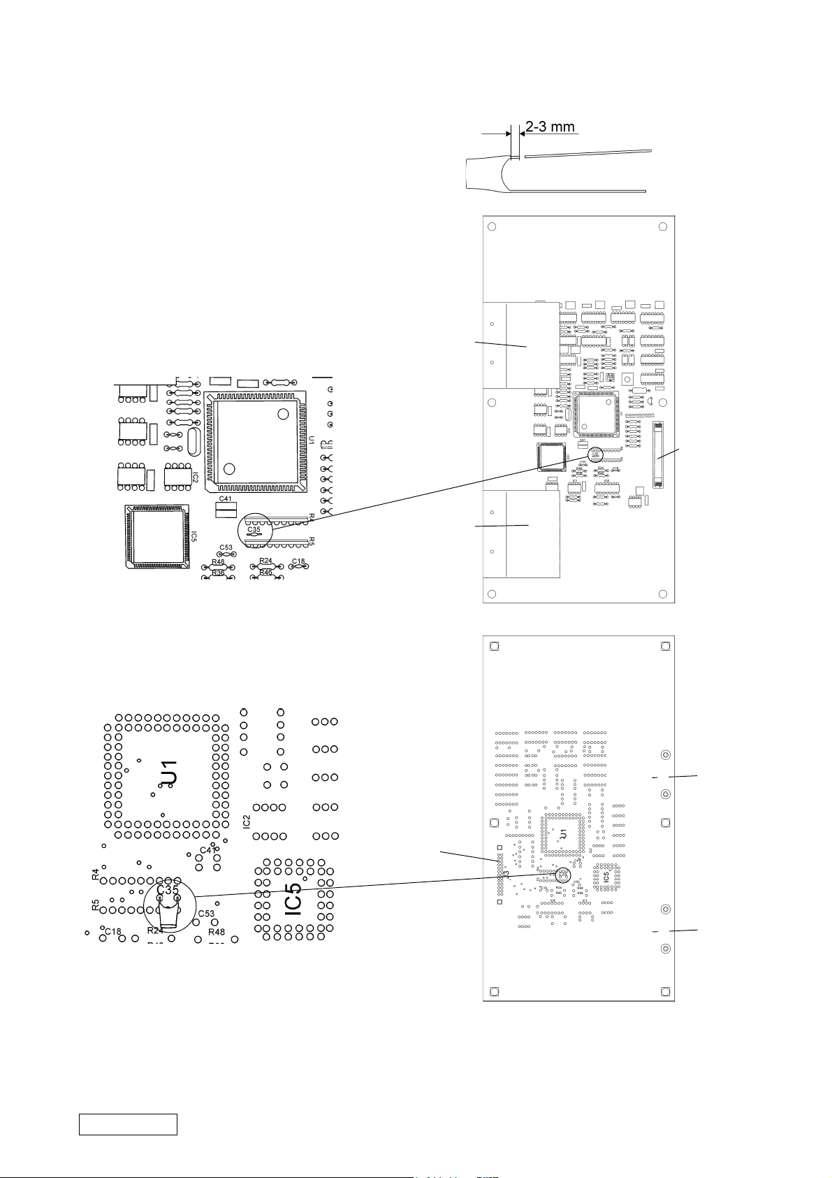
1. Cut off the legs of the new
capacitor so that 2-3 mm
remains.
2. Place the PCB face up with the
heat sinks to the left and
connector J3 to the right.
Capacitor C35 is located
between R4 and R5 just below
the processor. Cut off the
capacitor.
T09120
heat
sink
connector
J3
3. Turn the PCB over. Locate the
legs of the original capacitor.
Solder the new capacitor onto
the legs of the old one.
heat
sink
heat
sink
connector
J3
heat
sink
REINSTALLING
Installation is an exact reversed
procedudre of removal
Art. nr 45961 Sep 2000
Page 2 (13)
Page 3
T09120
UPGRADING SOFTWARE IN MODEL 45 AND MODEL 306/310
In order to run a system containing a Model 45, a Model 306/310 and a Model 46, the Model
45 and Model 306/310 requires certain software versions. This instruction describes how to
upgrade the Model 45 Mailer to software version 1.16 (or greater) and Collator Model 306/
310 to software version PL90 M 1.00 (or greater).
CHECK SOFTWARE VERSION MODEL 45
The actual software version is showed in the display on the control panel when the Model 45
is powered on.
CHANGING PROCESSOR MODEL 45
CAUTION: Always handle the PCB, EEPROM, micro processor etc. in accordance with electrostatic
discharge procedures (ESD). The PCB contains components that are sensitive to ESD
damage.
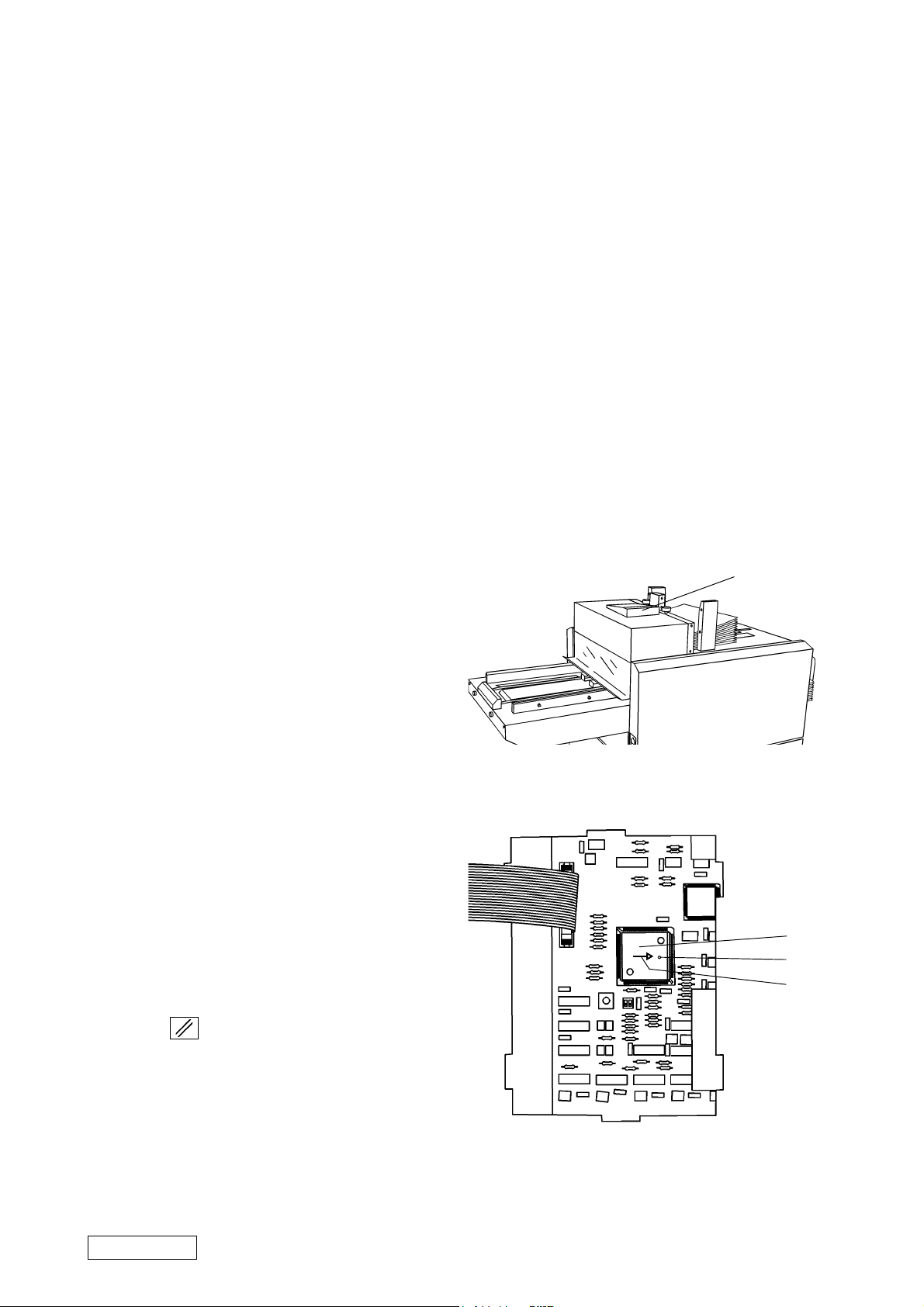
1. Switch off the main power switch and
disconnect power cord and connection
cable (if present).
2. Loosen the screw (1) on the back side of
the control panel.
3. Push the control panel towards the rear
side and lift it.
4. Remove the processor (2) using the
extractor tool (part No. 95147).
5. Install the new processor (software
version 1.16 or greater) by applying an
even pressure on the processor until it
is fully inserted.
NOTE 1: On the socket under the processor there
is an arrow (4). Install the processor so
that the arrow will be pointing towards
the small dent (3) on the processor.
NOTE 2: There is no need to manually reset the
EEPROM. The new software does that
automatically. However, when powered
up the first time after processor
replacement, press the reset button
( ) when called for.
6. Install the control panel in reversed
order.
1
2
3
4
Page 3 (13) Art. nr 45961 Sep 2000
Page 4
T09120
CALIBRATING MOTORS
After upgrading the software motors 3, 5 and 8 needs to be calibrated. Motors should allways
be allowed to cool off (if used) before calibration.
1
2
SELF DIAGNOSIS
CHECK MOTORS
CHECK SENSORS
VOLTMETER
ACTIVE STOP POS.
M1 RESERVED
M2 ENV. FLAP OP.
M3 ENV. POSITION
M4 ENV. OPNER
M5 PAPER TRANSP.
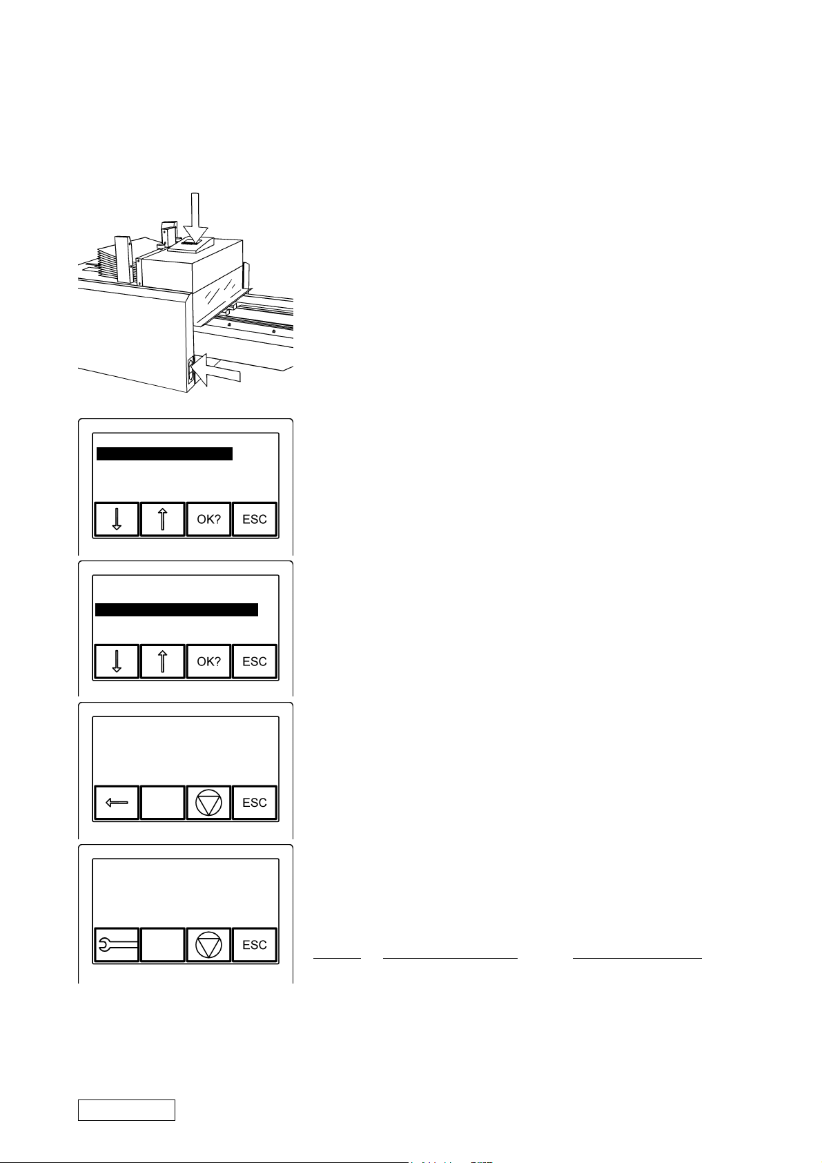
Enter the service mode by:
1. Pressing and holding the rightmost button pressed on
the control panel.
2. Switching on the power.
3. Choose “CHECK MOTORS” and press the “OK”
button.
4. Select motor and press the “OK” button
SPEED = 2.00 M/S
SPEED = 2.00 M/S
Art. nr 45961 Sep 2000
5. Run the motor by pressing the directional arrow
button.
6. Press the wrench button if the motor does not run at
the specified speed. The Model 45 will automatically
adjust the speed. Press the stop button to store
value.
Motor Normal reading Description
M3 SPEED=2,00 M/S ENV. POSITION
M5 SPEED=2,80 M/S PAPER TRANSP
M8 SPEED=2,90 M/S ENV. SEALING
7. After calibration, press the ”ESC” button one time
Page 4 (13)
Page 5
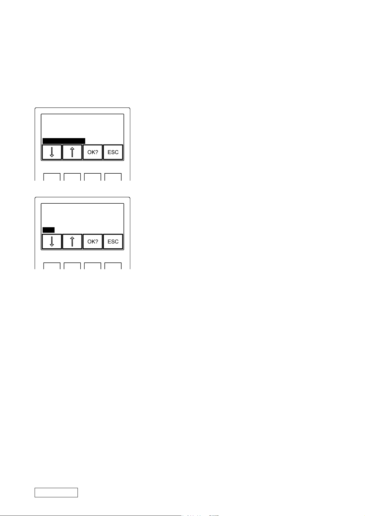
VERIFYING INTERFACE MODE
T09120
Using the Model 45 and Model 46 together in a system,
the Model 45 must be in interface mode ”CAN”. To verify
the interface mode:
ACTIVE STOP POS.
INSERT POSITION
DEAD CYCLING
TOTAL COUNTER
INTERFACE
MODE AUTO IS:
COLLATOR PL90
DFA
PL90 / STREAMFEED
CAN
1. Select ”INTERFACE” from the service menu.
2. Check that the Model 45 is set to interface mode
”CAN”. If not, select ”CAN” using the arrow buttons
and press the ”OK” button.
3. After changing/verifying the interface mode, press
the ”ESC” button once or twice (depending on
action taken). The Model 45 will now be in operator
mode.
4. Switch off the main power switch.
Page 5 (13) Art. nr 45961 Sep 2000
Page 6
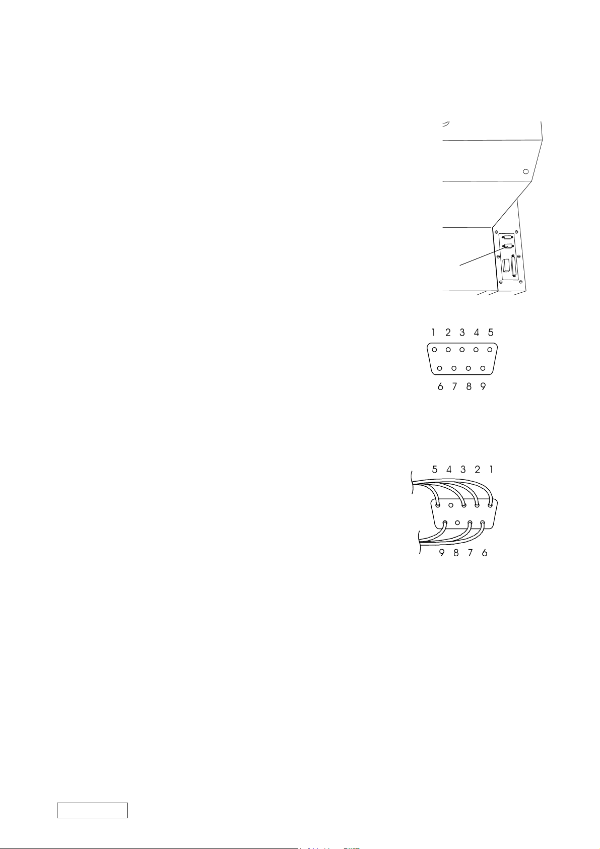
CHECKING THE 9 POLE D-SUB CAN CONNECTOR (P27)
Check that no wires are connected to pin 6 and pin 9 on
the lower 9 pole D-sub connector (P27) on the Model
45. If a black wire is connected to pin 6 and a violet wire
is connected to pin 9, cut and insulate them.
T09120
lower 9-pole
D-sub connector
From outside, look at the lower 9-pole D-sub connector to see
if pin 6 and 9 are present. If not present, no further action is
necessary.
If pin 6 and 9 are present, remove the rear cover to check if the
black wire connected to pin 6 and the violet wire connected to
pin 9 already has been cut. If not, cut and insulate them.
lower 9-pole D-sub connector,
outside view
lower 9-pole D-sub connector,
inside view
Art. nr 45961 Sep 2000
Page 6 (13)
Page 7
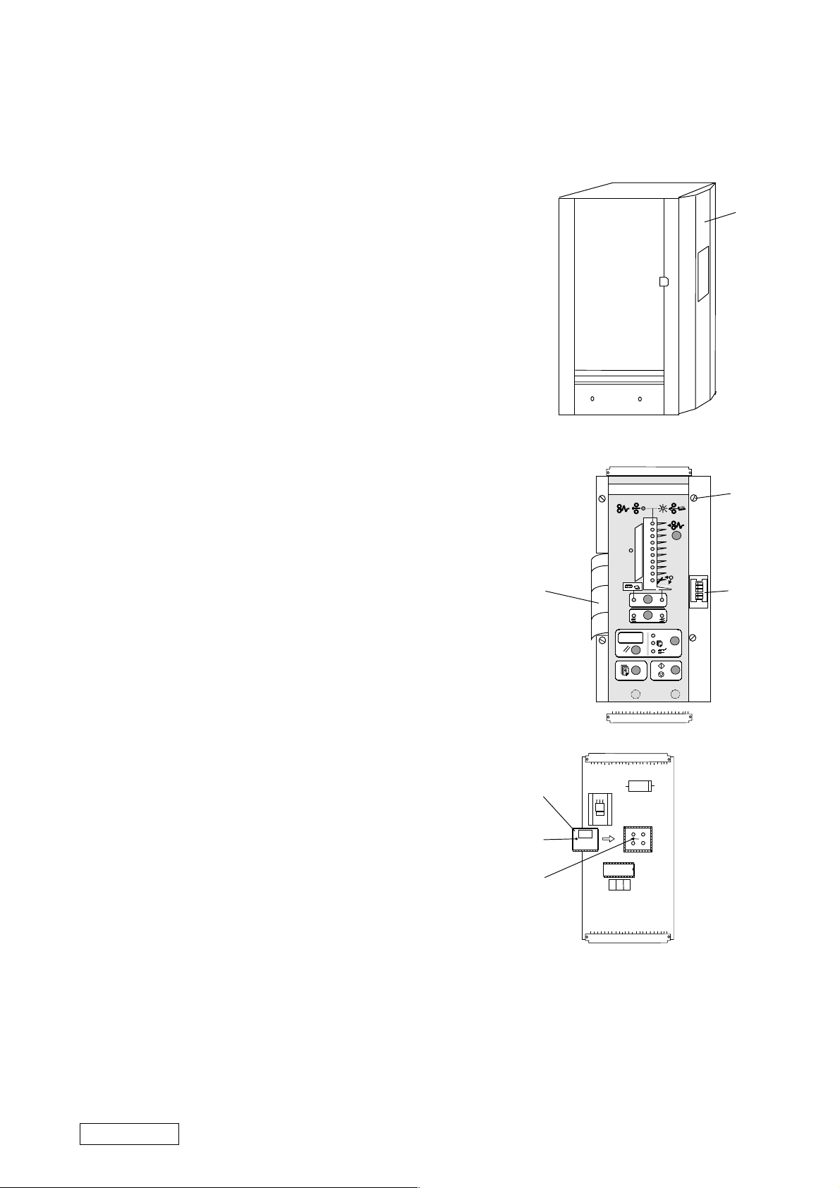
CHANGING PROCESSOR MODEL 306/310
CAUTION: Always handle the PCB, EEPROM, micro processor etc.
in accordance with electrostatic discharge procedures
(ESD). The PCB contains components that are sensitive
to ESD damage.
1. Switch off the main power switch and disconnect the
power cord.
2. Remove all sheet metal screws holding the front cover
(1) to the side frame.
3. Lift off the cover.
4. Disconnect the ribbon cable (2).
5. Remove the four counter sunk screws (3) and remove
the front panel assembly.
6. Remove the processor (5) using the extractor tool
(part No. 95147).
7. Install the new processor (software version
PL90 M 1.00 or greater) by applying an even
pressure on the processor until it is fully inserted.
T09120
1
3
1
2
3
4
5
6
7
8
9
10
2
1
2
3
4
4
NOTE: On the socket under the processor there is an arrow
(7). Install the processor so that the arrow will be
pointing towards the small dent (6) on the processor.
8. Mount the front panel assembly.
9. Reset the EE prom by sliding DIP switch no.3 (4)
to its rightmost position.
10. Switch on the main power switch, wait app. 5
seconds until ”HEL” appears on the display. The
values in the EE prom is now erased.
11. Switch off the main power switch and slide DIP
switch no. 3 back to its leftmost position.
12. Switch on the main power switch. The Micro processor will now load the EE prom with
the new values.
13. Switch off the main power switch and mount the
front cover.
5
6
7
VX
Page 7 (13) Art. nr 45961 Sep 2000
Page 8

T09120
PAGE INTENTIONALLY BLANK
Art. nr 45961 Sep 2000
Page 8 (13)
Page 9
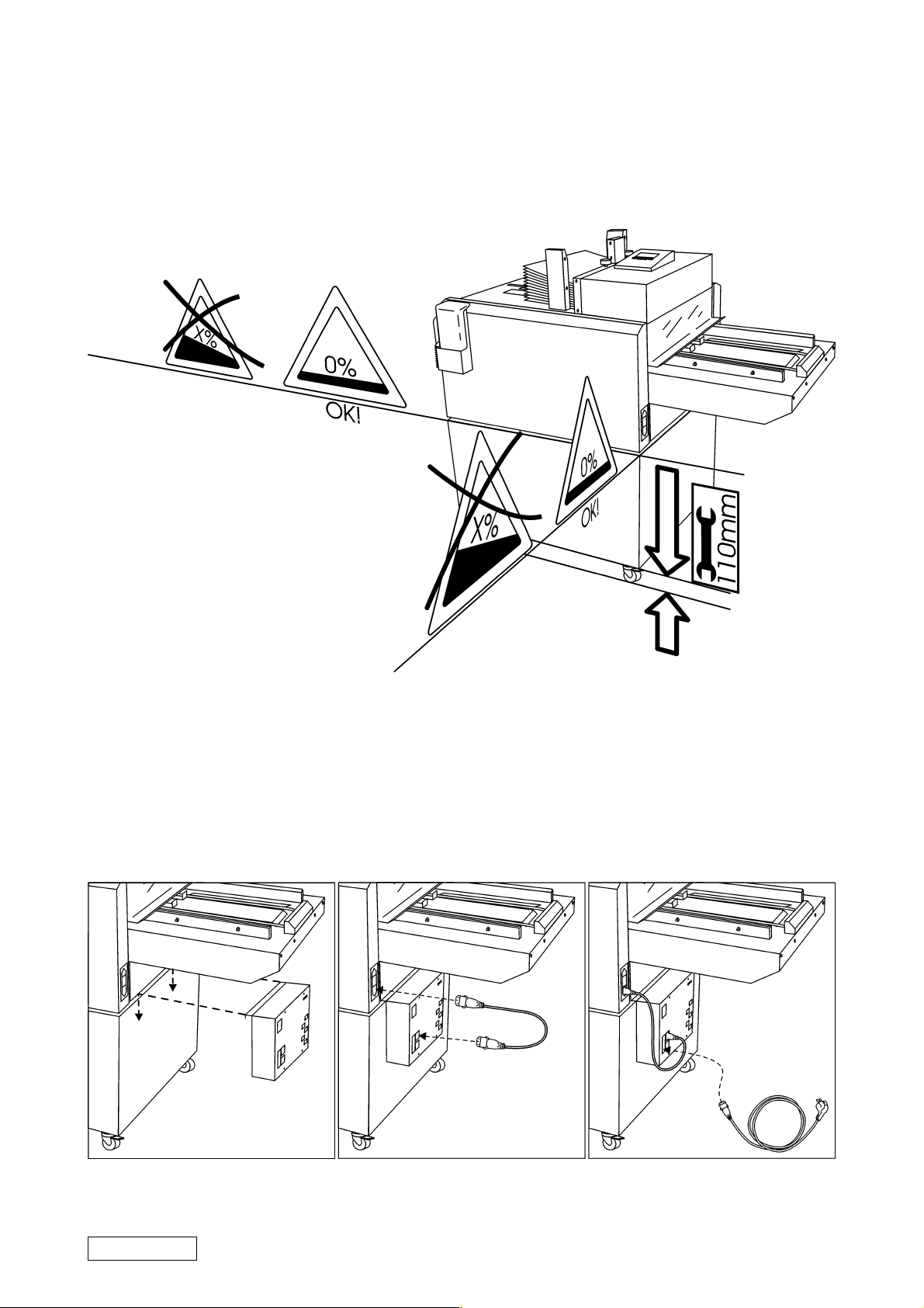
ADJUSTING THE MODEL 45 HEIGHT
T09120
CONNECTING THE POWER PACK
Page 9 (13) Art. nr 45961 Sep 2000
Page 10
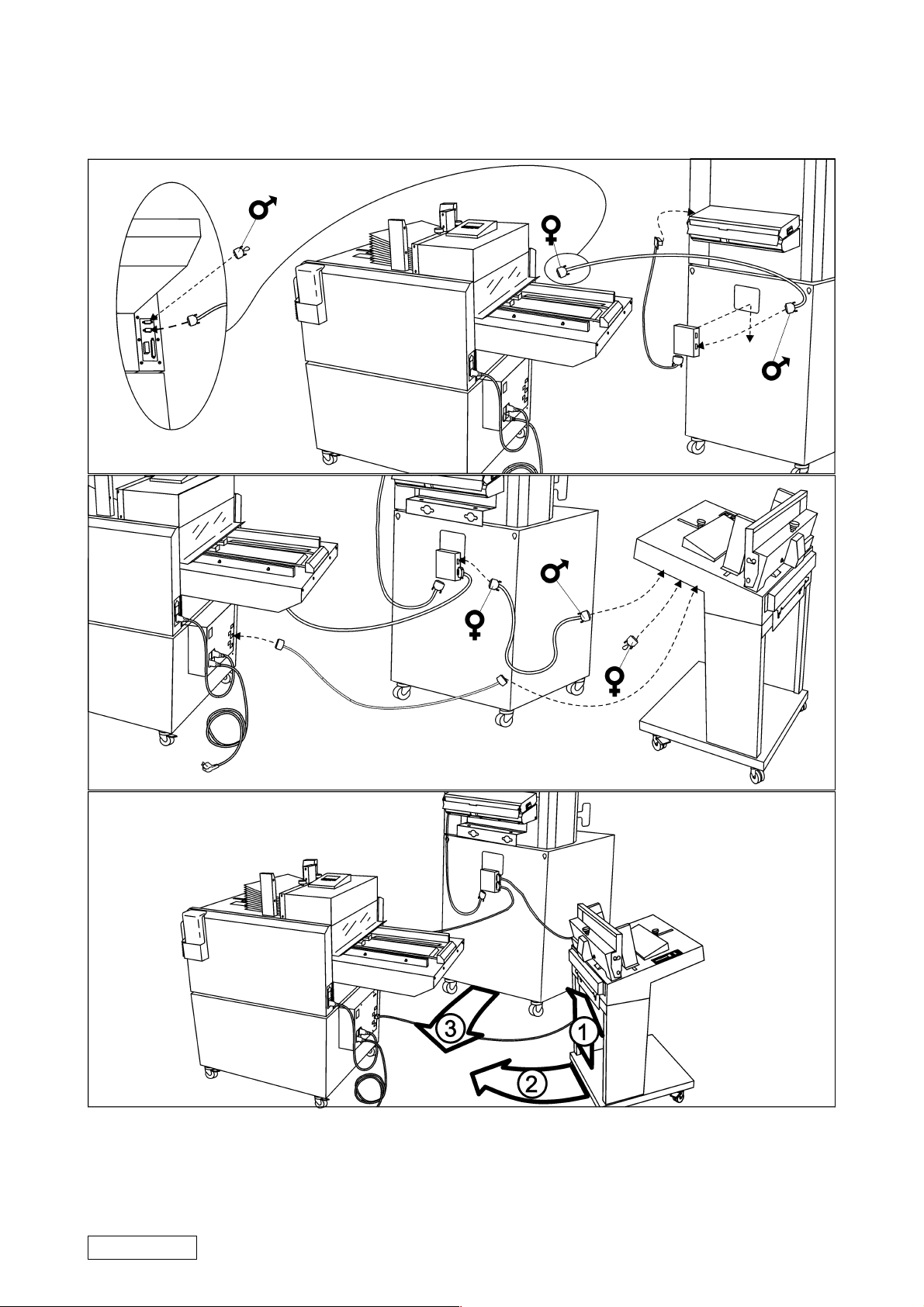
CONNECTING MODEL 46, MODEL 45 AND MODEL 306/310
T09120
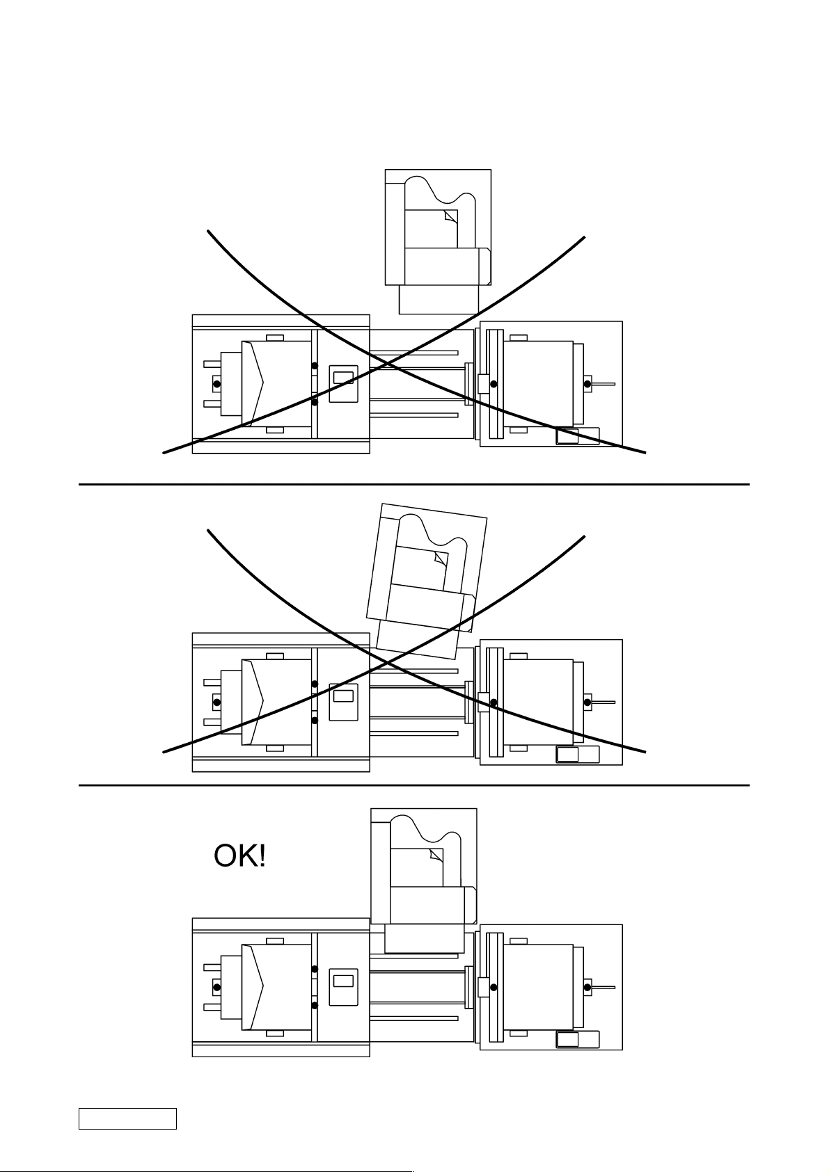
Lift the the Model 46 docking plate (1) and position the Model 46 to the Model 45 (2). Ensure
that the docking plate locks the Model 46 to the Model 45. The Model 306/310 should be
positioned between Model 45 and Model 46 (3), square with document table and as close to
the document table as possible.
Art. nr 45961 Sep 2000
Page 10 (13)
Page 11
T09120
Page 11 (13) Art. nr 45961 Sep 2000
Page 12

T09120
PAGE INTENTIONALLY BLANK
Art. nr 45961 Sep 2000
Page 12 (13)
Page 13
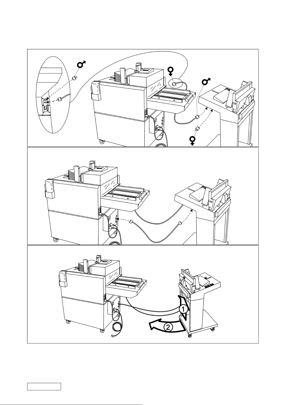
CONNECTING MODEL 46 AND MODEL 45 ONLY
T09120
Lift the the Model 46 docking plate (1) and position the Model 46 to the Model 45 (2). Ensure
that the docking plate locks the Model 46 to the Model 45.
Page 13 (13) Art. nr 45961 Sep 2000
 Loading...