

Page 1
OPERATION MANUAL
UCHIDA YOKO CO., LTD., TOKYO, JAPAN
Jul 23, 2012 USA
Page 2

• Use machine only after reading the "Safety Instructions" given below carefully.
• These safety instructions are given to ensure that the machine will be used safely
and properly and to prevent operators from sustaining harm and injuries.
SAFETY INSTRUCTIONS
Definition of Symbols and Notes
In this manual the following names and signs stand for possible dangers.
Danger
This symbol stands for immediate danger threatening the life and
health of persons. Disregarding these instructions may cause
severe damage to health and even serious injuries.
Caution
This symbol stands for an endangering situation that may occur.
Disregarding these instructions may lead to slight injuries or
damage to property.
Note
This symbol stands for notes, operational hints, and other useful
information.
They are convenient for exploiting the machine’s functional abilities.
1
Page 3

SAFETY INSTRUCTIONS
Explanations of the illustrations used in the Safety Instructions are given as follows:
Danger
1. Don't open the cover of the equipment. There is a danger of receiving an injury
or electric shock.
2. Turn off the power supply beforehand when attaching or detaching the
perforating blade. There is a danger of receiving an injury.
3. Don't touch any rotating part. There is a danger of receiving an injury.
2
Page 4

Caution
1. Don't put a hand into the cover or a clearance between parts. There is a
danger of receiving an injury.
2. Don't bring a hand, face, hair, sleeves of clothes and the like close to the
rotating parts of the machine. There is a danger of receiving an injury.
3. Don't touch the blade point of the cutter. There is a danger of receiving an
injury.
4. Don't touch the blade point of the perforating blade. There is a danger of
receiving an injury.
5. Turn off the power supply beforehand when setting the feed table.
There is a danger of receiving an injury.
6. Turn off the power supply beforehand when setting the stacker. There is a
danger of receiving an injury.
7. Turn off the power supply beforehand when setting the waste bin. There is a
danger of receiving an injury.
8. Turn off the power supply beforehand when removing paper scraps. There is
a danger of receiving an injury.
9. For the perforator, papers of weight 65 lbs (Cover stock) [176 g/㎡] or less is to
be used. Using heavier paper may cause a paper jam or mechanical failure.
10. Do not exceed the MAX level when stacking the paper. Exceeding it may
cause a mechanical failure.
11. Turn off the power supply beforehand when starting maintenance or
inspection. There is a danger of receiving an injury.
12. When you install a machine, please install to a place with no dust, and the
place which is not influenced with a liquid. It becomes the cause of failure if
the installation method is mistaken.
13. When you put a machine into operation, please change into the state
where all covers were closed. If it works where a cover is opened, there is
fear of an injury.
3
Page 5

Introduction
Read this "Operation Manual" carefully before use. In particular, be sure to read "Safety
Instructions" (page 2 to page 3) to ensure that the machine will be used properly.
Keep the manual at an appointed place with care so that it may be accessible whenever
necessary.
The specifications of this product are subject to change for improvement. Therefore,
don't mistake the "Operation Manual" of one product of the same model for that of
another because descriptions in the "Operation Manual" of products of the same model
may differ.
4
Page 6

Contents
1. Before use........................................................................................................................................ 7
(1) Description and quantities of accessories...................................................................................7
(2) Exterior features.......................................................................................................................... 8
(3) Installation................................................................................................................................10
2. Operating instructions ...................................................................................................................11
(1) Checks before use ...................................................................................................................11
(2) Setting of stacker......................................................................................................................11
(3) Waste box setting.....................................................................................................................12
(4) How to attach the business card stacker..................................................................................12
(5) Paper setting............................................................................................................................13
(6) Paper slant adjustment.............................................................................................................14
(7) Separator adjustment...............................................................................................................14
(8) Paper feed detection plate adjustment.....................................................................................15
(9) Blow rate adjustment................................................................................................................15
(10) Crease depth adjustment.......................................................................................................16
(11) How to remove the crease unit...............................................................................................17
(12) How to attach the perforator...................................................................................................18
(13) How to adjust the perforation location....................................................................................19
(14) How to adjust the depth of perforation....................................................................................
(15) How to replace the perforation Lower Blade...........................................................................22
3. Operational method.......................................................................................................................23
(1) Basic operation.........................................................................................................................23
(2) Slitter initial location movement................................................................................................23
(3) Format selection.......................................................................................................................24
(4) Free entry.................................................................................................................................27
(5) User program retrieval (MANU SET)........................................................................................28
(6) User program registration (MANU SET)...................................................................................29
(7) FLEX entry ...............................................................................................................................31
(8) User program retrieval (FLEX MODE)......................................................................................34
21
(9) User program registration (FLEX MODE).................................................................................35
(10) Setting of slitter and feed table...............................................................................................37
(11) Operation number cancellation...............................................................................................37
(12) Manual operation and Speed Change....................................................................................38
(13) Cut mark on/off selection........................................................................................................39
(14) Automatic operation................................................................................................................40
5
Page 7

4. Instructions for use........................................................................................................................41
(1) If the machine stops during operation ......................................................................................41
(2) If Paper scrap remains on the machine....................................................................................42
(3) Details concerning errors..........................................................................................................43
(4) If the cut measurement does not match the input value...........................................................49
5. Product specifications ...................................................................................................................50
6. Equipment, Electric circuit and parts.............................................................................................52
7. Ordering consumables, etc. ..........................................................................................................55
6
Page 8
1. Before use
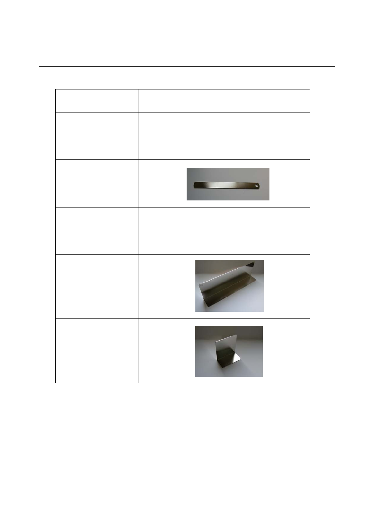
(1) Description and quantities of accessories
Electric power cord
Hexagonal wrench
Tweezers 1pc.
Waste ejector
Instruction manual 1pc.
Waste box 1pc.
Paper guide (Large)
1pc.
0.08” X 1pc.
1pc.
1pc.
5pc.
Paper guide (Small)
7
Page 9
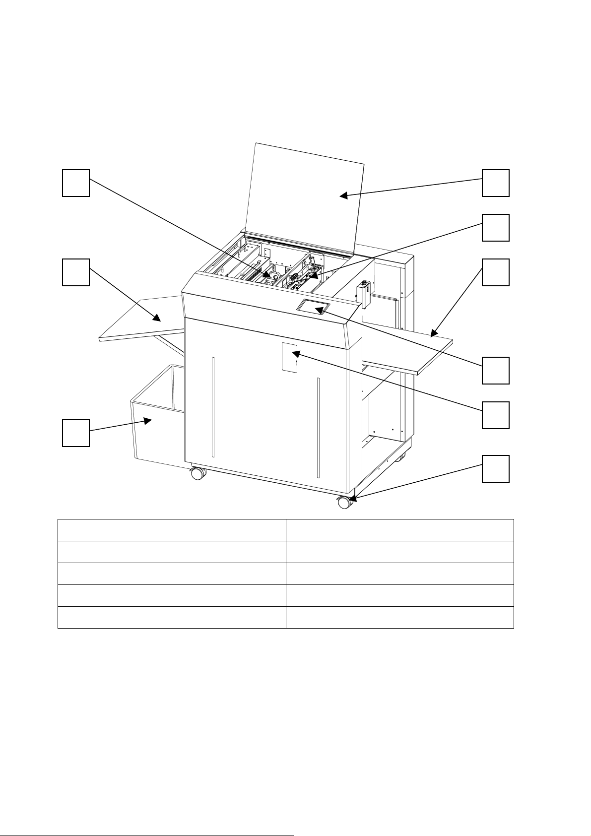
(2) Exterior features
1. Name of parts
41
2
3
5
6
7
8
9
1. Slitter 6. Feed Table
2. Stacker 7. Touch Panel
3. Waste Box 8. Adjustment Door
4. Safety Cover 9. Caster
5. Perforator cartridge
8
Page 10
1 3
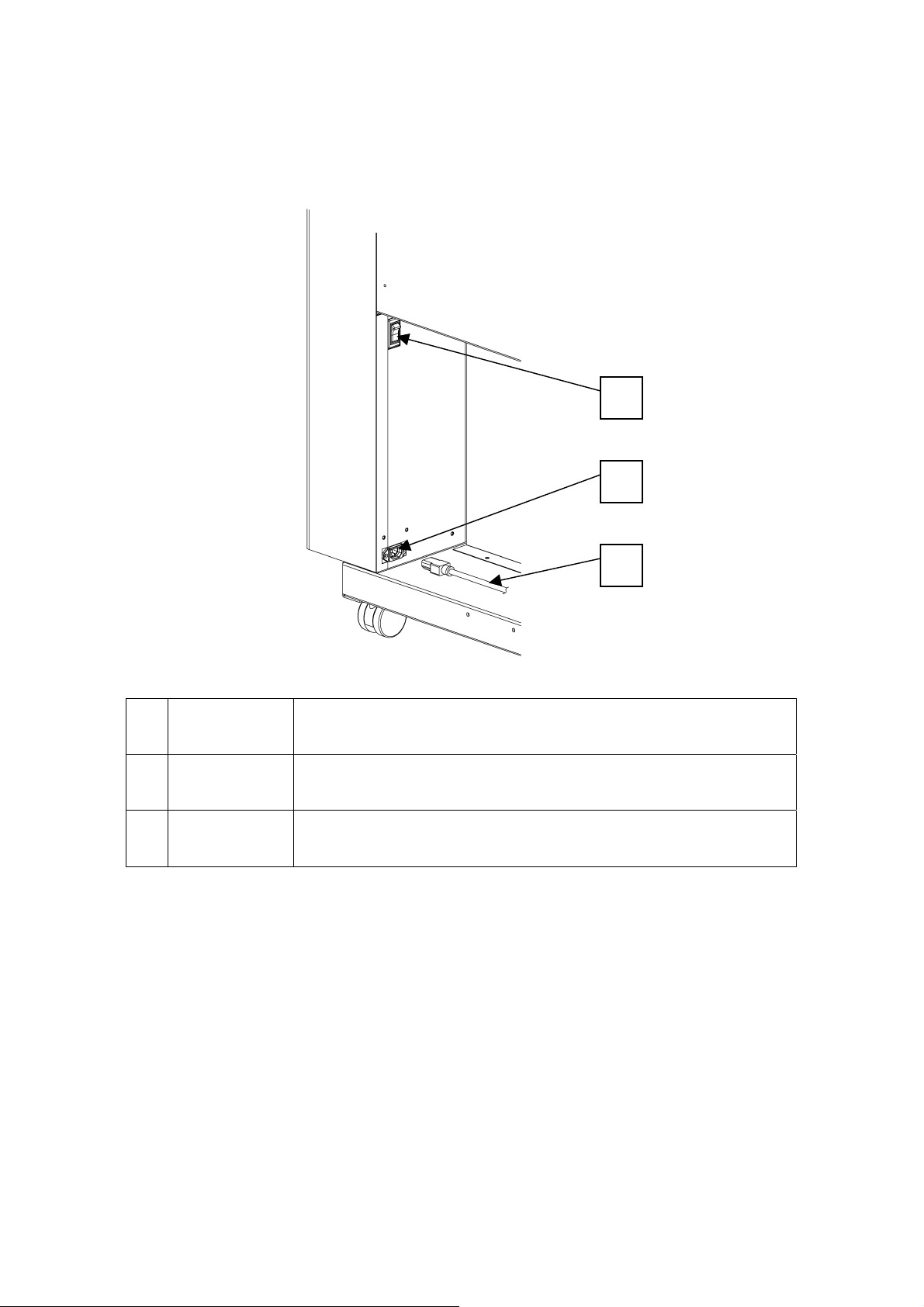
2. Electric-power-related points
The electric power switch and the inlet are located inside the machine, below
the feed table.
2
1
Power switch
2
Electric Power
3
Inlet
Cord
① When it is set at “I”, the power is turned on.
② When it is set at “O”, the power is turned off.
Plug in the electric power cord here.
Plug this to the inlet.
9
Page 11
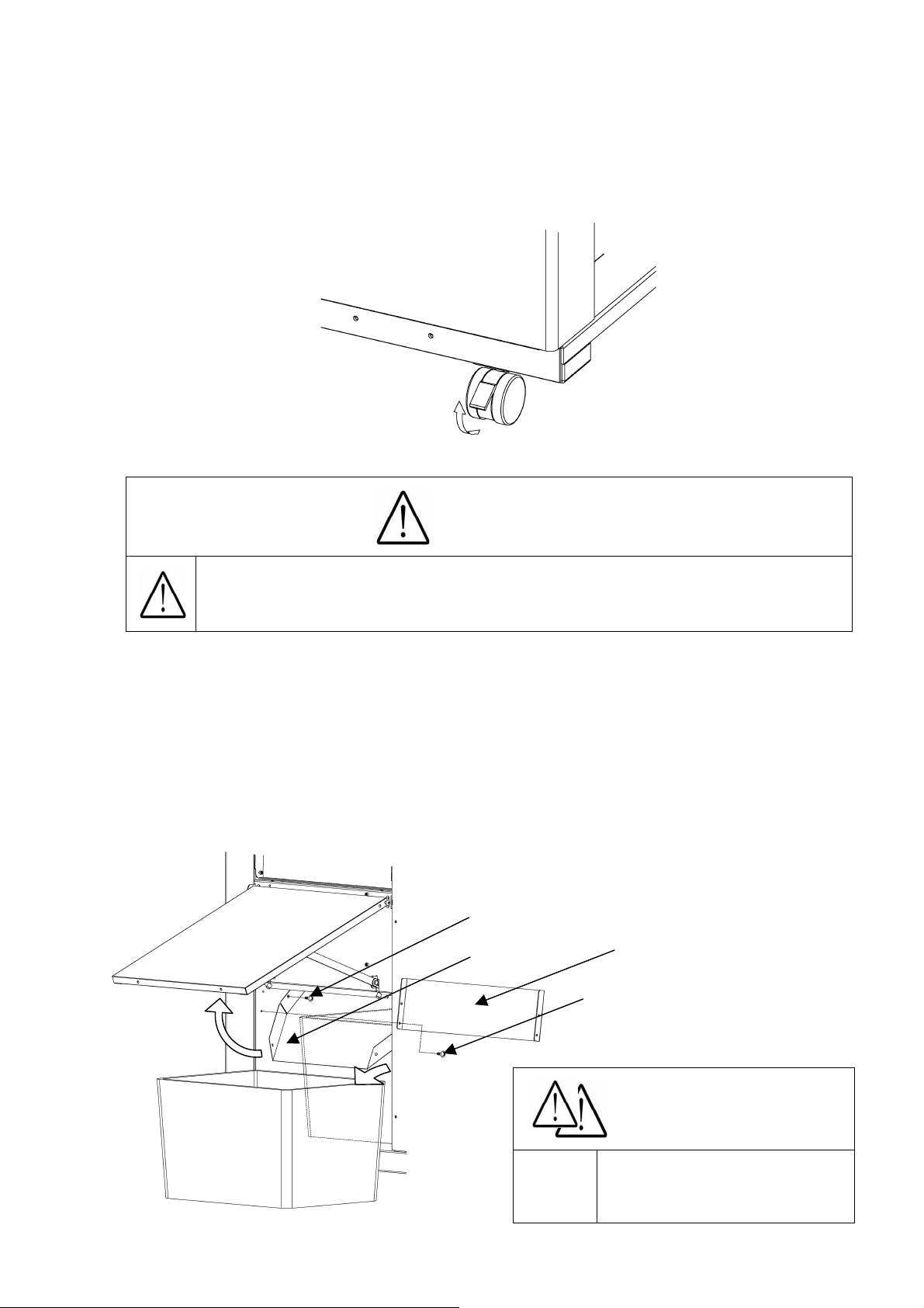
(3) Installation
1.
The
machine installation method
Please be sure to LOCK a caster brake after making it move to the target position, when
installing a machine.
Unlock
2. How to remove accessories
① Loosen the screws to remove the chute guide.
② Remove the chute screws.
③ Lift the chute and take out the waste box.
④ The accessory case is inside the waste box.
⑤ Reposition the chute guide.
When you install a machine, please install to a place with no dust,
and the place which is not influenced with a liquid. It becomes the
cause of failure if the installation method is mistaken.
Lock
Caution
Screws
Chute
Chute guide
Screws
Caution
Waste box
10
Power it off. Otherwise,
Injury could occur.
Page 12
2. Operating instructions
(1) Checks before use
Check the following before operation.
① Is the electric power turned off?
② Is the feed table set?
③ Is the stacker set?
④ Is the electric power cord plugged in?
⑤ Is the waste box set?
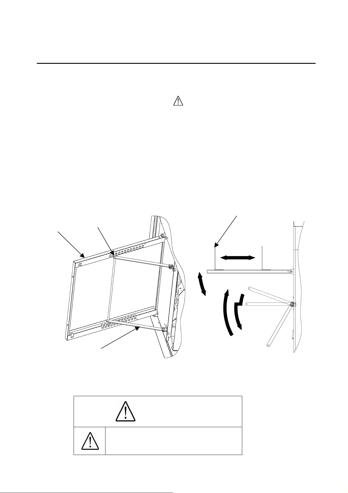
(2) Setting of stacker
Stacker
Indentation
Paper Guide (Large)
① Open the stacker and set the stays in the indentation of the back of the stacker at an
appropriate angle to allow smooth paper ejection.
② Adjust the large paper guide according to the paper size.
Stay
Caution
Power it off. Otherwise,
Injury could occur.
11
Page 13
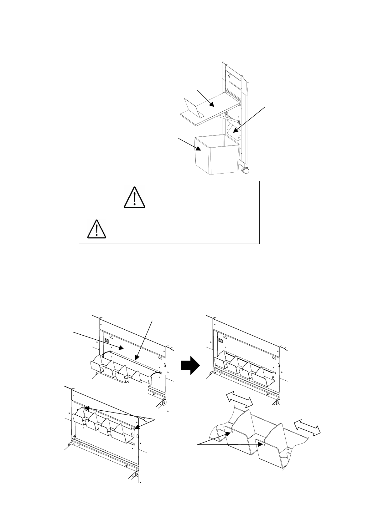
(3) Waste box setting
① Set the waste box under the stacker.
Waste box
Caution
Power it off. Otherwise,
Injury could occur.
Stacker
Chute
(4) How to attach the business card stacker.
① Hang the business card stacker on Paper ejection port of Stacker panel.
② Find the V- notch to see where to put the business card stacker.
③ When it is not used, it may be hooked to the upper holes in the stacker panel.
Stacker panel
Paper ejection port
Upper holes
V-notch
12
Page 14
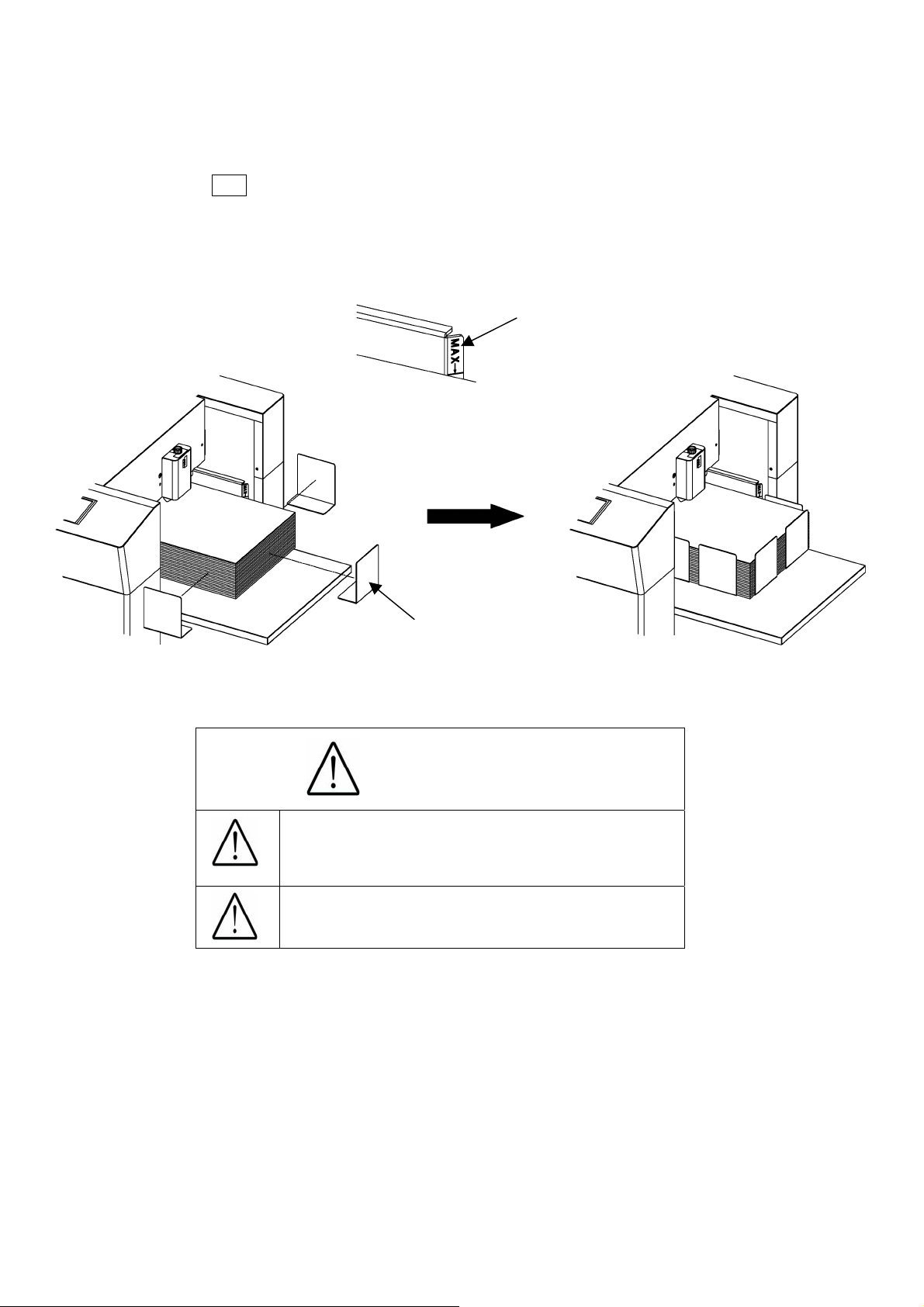
(5) Paper setting
① Press SET to lower the feed table.
② Separate the sheets of paper well and place them on the feed table.
③ Fix the paper with the small paper guides.
④ Make sure that the paper stack does not exceed the MAX label.
MAX Label
Paper Guide (Small)
Caution
Ensure that the paper stack does not
exceed the MAX label, as it may cause
a mechanical failure.
Separate the sheets of paper well, as it
may cause a paper jam.
13
Page 15
A
A
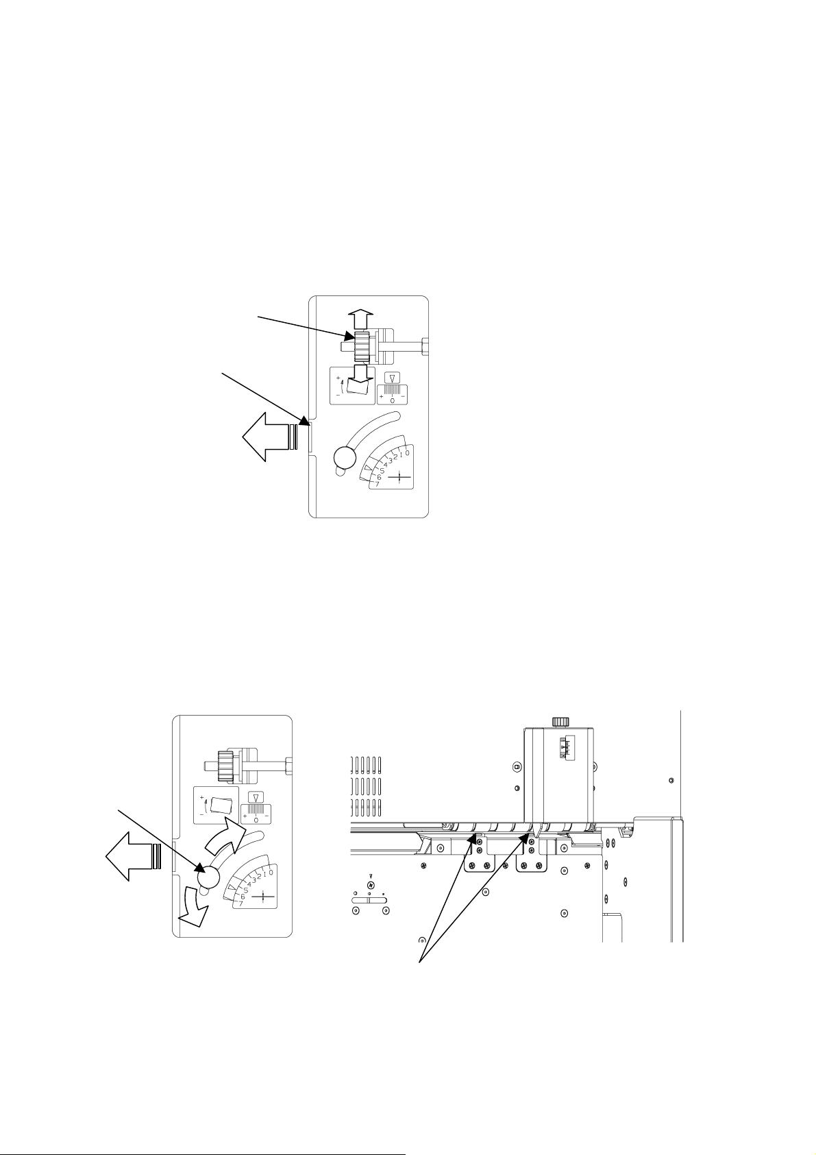
(6) Paper slant adjustment
① Open the adjustment door on the front side of the main body.
② When the printing is tilted, turn the dial as shown in the drawing below to make it straight.
③ Turning the dial up will tilt the paper to the right, whereas turning it down will tilt the paper
to the left.
④ A graduation of “0” indicates the straight position.
djustment door
djustment dial
(7) Separator adjustment
① Open the adjustment door on the front side of the main body.
② Loosening the knob, adjust it upward when double feeds tend to occur, and adjust it
downward when the paper is not smoothly fed.
Knob
Separator
14
Page 16
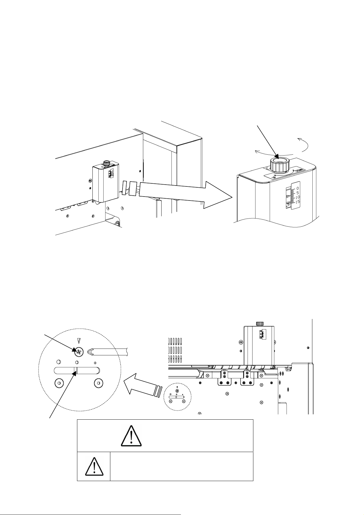
(8) Paper feed detection plate adjustment
① Use the paper feed detection plate adjustment dial for this adjustment.
② Turn it counterclockwise (down) when the paper tends to be doubly fed, and turn it
clockwise (up) when the paper is not smoothly fed.
③ When the paper tends to be slantly fed, move the plate upward.
Paper feed defection
plate adjustment dial
Down
Up
(9) Blow rate adjustment
① Power it off.
② Loosen a screw located on the far side of the paper feeder and put the tip of the
Screw
Slit
screwdriver into the slit below to adjust it to the right and left.
③ Adjust to the right (lower blow rate) when the paper tends to be doubly or slantly fed or it is
thin, and to the left (higher blow rate) when the paper is not smoothly fed or it is thick.
Caution
Power it off. Otherwise,
Injury could occur.
15
Page 17
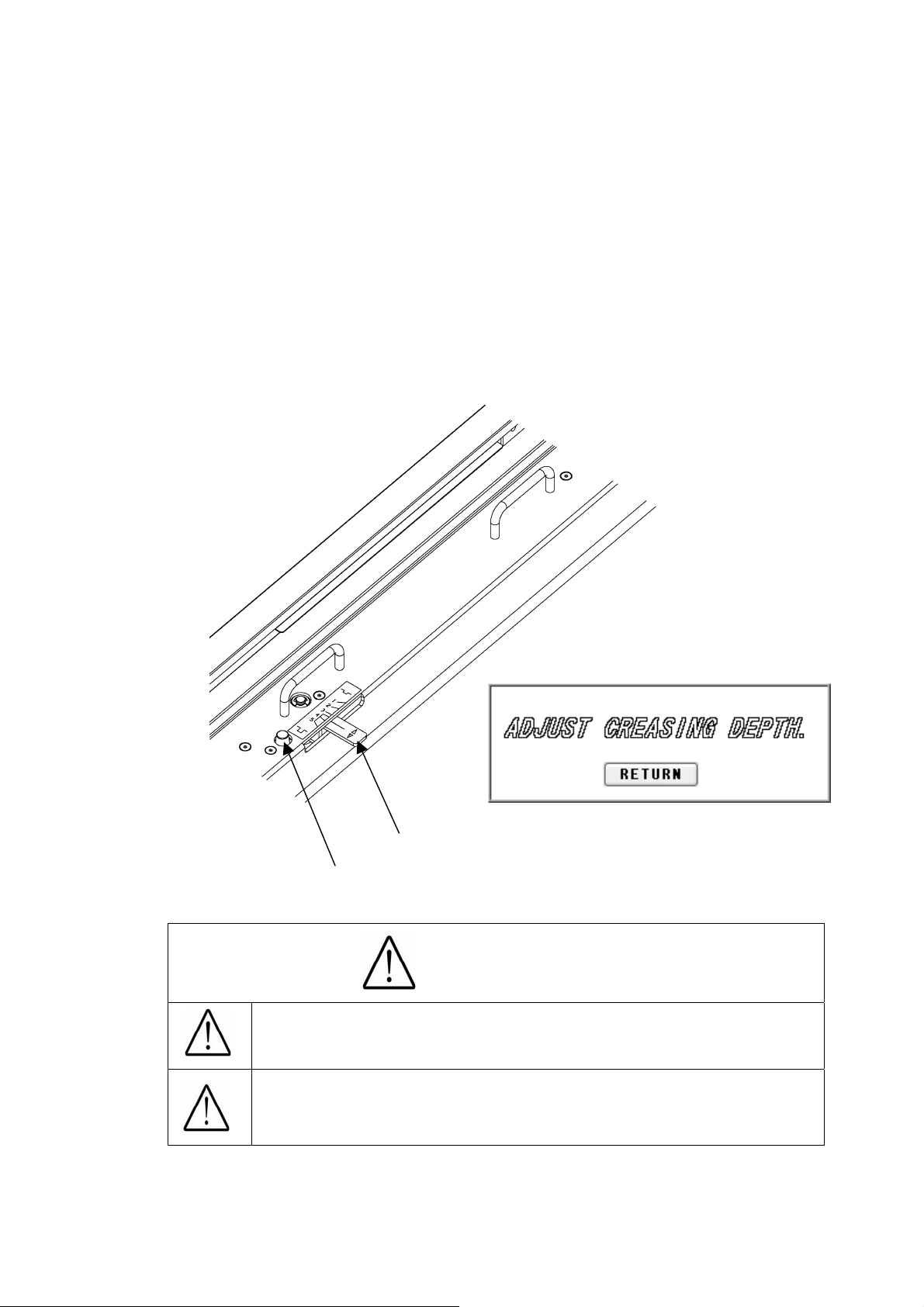
(10) Crease depth adjustment
① The sign shown in the drawing below will be displayed when using the creaser.
② Turn the dial shown in the drawing below to adjust the crease depth.
③ The depth will become the most shallow by choosing Level 1 and the deepest by choosing
Level 5.
④ When choosing Level 4 or 5, turn a lever while pressing a button on the near side. To
return to Level 3 or lower, simply turn the lever.
⑤ When selecting Levels 4 and 5, be careful of the paper thickness. Placing the crease too
deep may cause a paper jam or a mechanical failure when the paper is thick.
Button
Lever
Caution
Avoid the combined use of the creaser and the perforator,
as it may cause a paper jam or a machine failure.
When selecting Levels 4 and 5, be careful of the paper
thickness. Placing the paper too deep may cause a
paper jam or a machine failure when the paper is thick.
16
Page 18
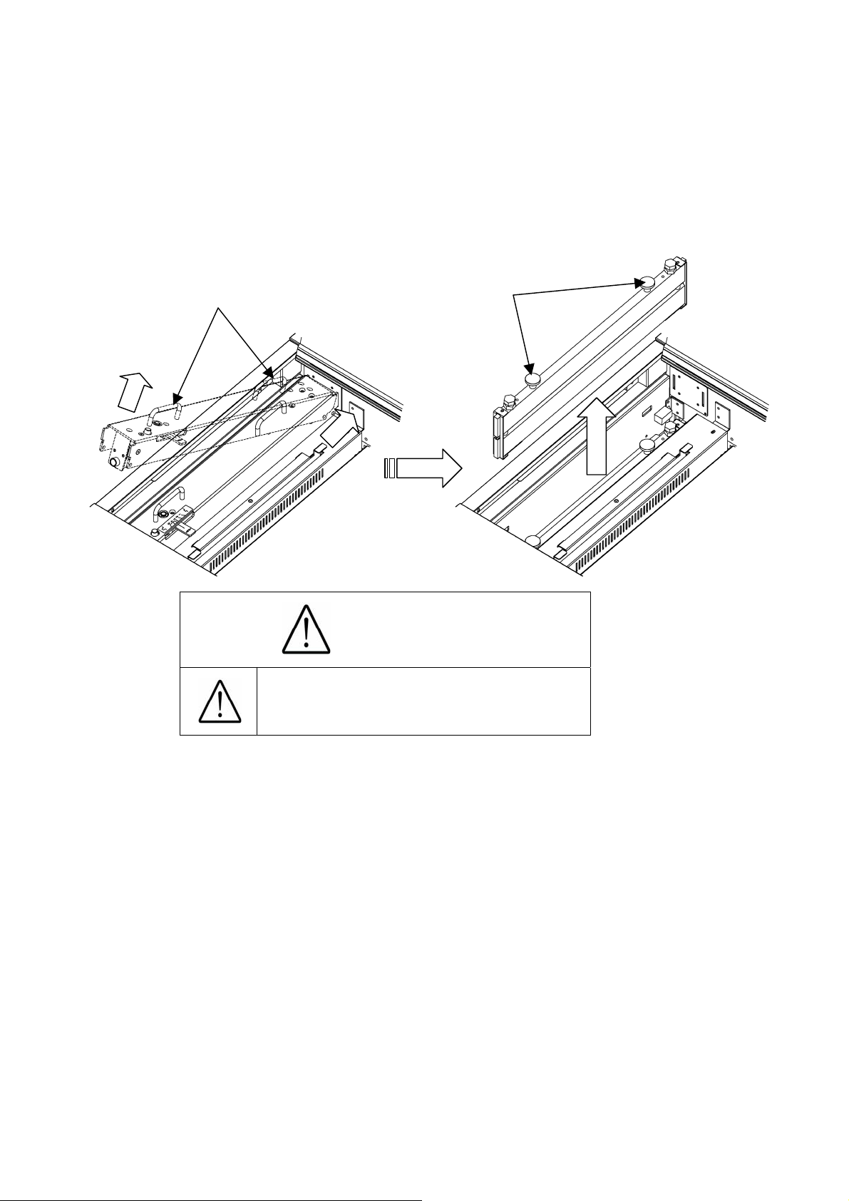
(11) How to remove the crease unit
① Power it off.
② Be sure to hold the upper handles of the crease unit with both hands. Pushing it to the far
side, lift the handle on the near side to remove the upper part of the crease unit.
③ Then, hold the knobs of the crease unit with both hands and pull it out upward.
Handle
Knob
Caution
Power it off. Otherwise,
Injury could occur.
17
Page 19

(12) How to attach the perforator
① Power it off.
② Be sure to hold the perforator with both hands and attach it as shown in the figure.
③ Attach it in such a manner that the projection is positioned as shown in the figure.
④ Fix at 2 spots with knurled head screws.
⑤ The target paper weight for the perforator is
Perforator
Knurled head screw
65 lbs (Cover stock) [176 g/㎡] or less.
Projection
Knurled head screw
Caution
Power it off. Otherwise,
Injury could occur.
The maximum paper weight for use is 65 lbs (Cover
stock) [176 g/㎡] for the perforator. Using a heavier
paper may cause a paper jam or a mechanical
failure.
Combined use of the perforator and creaser may
cause a paper jam or a mechanical failure
18
Page 20
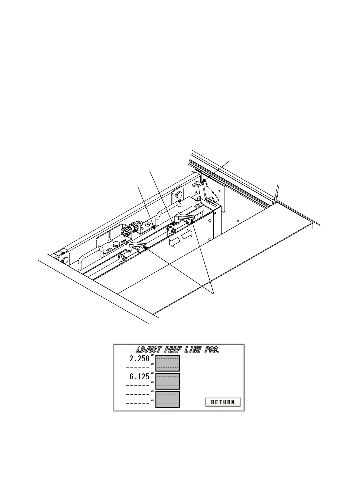
(13) How to adjust the perforation location
① When using the perforator, the screen will display where to fix the perforator, as shown
below.
② If the upper blades are positioned to come into contact with the lower blades, the upper
blade position can be adjusted with the perforator attached to the main body.
③ Shift the perforator lock lever to the right. Loosen the clamp levers, move the perforator to
the desired position based on the scale, and tighten the clamp levers firmly.
④ Shift the perforator lock lever to the left to finish this adjustment.
Upper Blade
Perforator lock lever
Scale
Clamp lever
19
Page 21

⑤ If the upper blades are not positioned to come into contact with the lower blades, remove
the perforator from the main body for adjustment.
⑥ Remove the perforator in the reverse order of the procedure described in (12) (How to
attach the perforator).
⑦ Loosen the two knurled head screws to remove the perforator cartridge cover.
⑧ Shift the perforator lock lever to the right. Loosen the clamp levers, move the perforator to
the desired position based on the scale, and tighten the clamp levers firmly.
⑨ Then, loosen screws with an accessory wrench and adjust the lower blade position to near
the center of the upper blades.
⑩ Put the perforator back on the main body and you are finished with this adjustment.
Perforator lock lever
Knurled head screw
Hexagonal Wrench
Perforator cartridge cover
Upper Blade
Upper Blade
Scale
Lower Blade
Caution
Avoid the combined use of the creaser and the
perforator, as it may cause a paper jam or a
mechanical failure.
Avoid contacting the cutting edge of the
perforating blade. Otherwise, injury could occur.
20
Page 22

(14) How to adjust the depth of perforation
① Change in the paper thickness, recommend you adjust the depth of Perforation.
② The height of the upper blades can be individually adjusted.
③ Remove the perforator by reversing the procedure described in (12) (How to attach the
perforator).
④ Shift the perforator lock lever to the right and raise the upper blades.
⑤ Adjust a height adjustment screw in the up direction if it is cutting into too deeply, and in the
down direction if not cutting into sufficiently.
Up=Shallow
Down=Deep
Perforator lock lever
Height adjustment screw
Knurled head screw
Perforator cartridge cover
Shallow
Deep
Caution
Avoid contacting the cutting edge of the
perforating blade. Otherwise, injury could occur.
21
Page 23

t
(15) How to replace the perforation Lower Blade
① As the lower blades of the perforator repeatedly cut the paper, the paper finish condition
degrades.
② If this is the case, shift the lower blade position slightly.
③ If the lower blades cannot be shifted any more, it is necessary to replace them.
④ Remove the perforator by reversing the procedure described in (12) (How to attach the
perforator).
⑤ Shift the perforator lock lever to the right and raise the upper blades.
⑥ Remove the hexagon socket set screws from the lower blades.
⑦ Remove two screws, followed by the cartridge bearing lid.
⑧ Remove the ball bearing, plain washer, and spring, and pull out the lower blades.
⑨ Replace them with new ones and assemble by reversing the removal procedure.
Knurled head screw
Hexagon socke
set screw
Perforator cartridge cover
Perforator lock lever
Upper Blade
Upper Blade
Spring
Plain washer
Ball bearing
Screw
Lower Blade
Cartridge bearing lid
Caution
Avoid contacting the cutting edge of the
perforating blade. Otherwise, injury could occur.
22
Page 24

3. Operational method
(1) Basic operation
① Turning the power on.
② Slitter initial location movement (When turning the power on initially and after adjusting
the head location)
③ Format selection/free entry, user program retrieval, etc.
④ Slitter and table setting
⑤ Creaser adjustment (when using the creaser)
⑥ Perforator adjustment (when using the perforator)
⑦ Paper setting
⑧ Sample cutting
⑨ Input value correction and size correction
⑩ Start of operation
(2) Slitter initial location movement
(When initially turning the power on
and after adjusting the head location)
① Turn the power on.
② Press INITIAL POSITION from the operation screen.
③ The slitter will move to the initial position.
④ The INITIAL POSITION sign will change to SET upon completion.
Operation
Screen
23
Page 25

(3) Format selection
① Press PRESET.
Operation
Screen
② Select the paper type to be used.
Paper Selection
Screen
24
Page 26

/
③ Select the cutting pattern.
Move to Cutting Pattern
Confirmation Screen
Cutting Pattern
Selection Screen
④ Cutting pattern content confirmation and partial correction
Press A through N to make corrections. O, P and Q are automatic calculations. It is
possible to enter in inches up to the 3rd decimal place.
Confirm cutting pattern and
move to Operation Screen
Cutting pattern switching
Return to Paper
Selection Screen
Feed direction
Creasing can be performed up to six
times per piece. It is not to be used in
combination with the perforator.
The maximum paper weight for the
perforator is 65 lbs (Cover stock) [176 g
㎡]. It is not to be used in combination with
the creaser.
25
Page 27

Q
G
R
A
MNO
F
B
Cutting Pattern
Confirmation Screen
P
C
S
EH
Number of pieces in the
depth direction
Number of pieces in the
feeding direction
D
Confirm cutting pattern
and move to Operation
Screen
Return to Cutting Pattern
Selection Screen
Please use as a
calculator
Crease Pos.
Input Screen
I J K L
Confirm input
value and return
Cancel input value
and return
Return to Cutting Pattern
Confirmation Screen
Touch it when you do not want to make
any crease. I,J,K,L,M,N will be0.000”.
26
Page 28
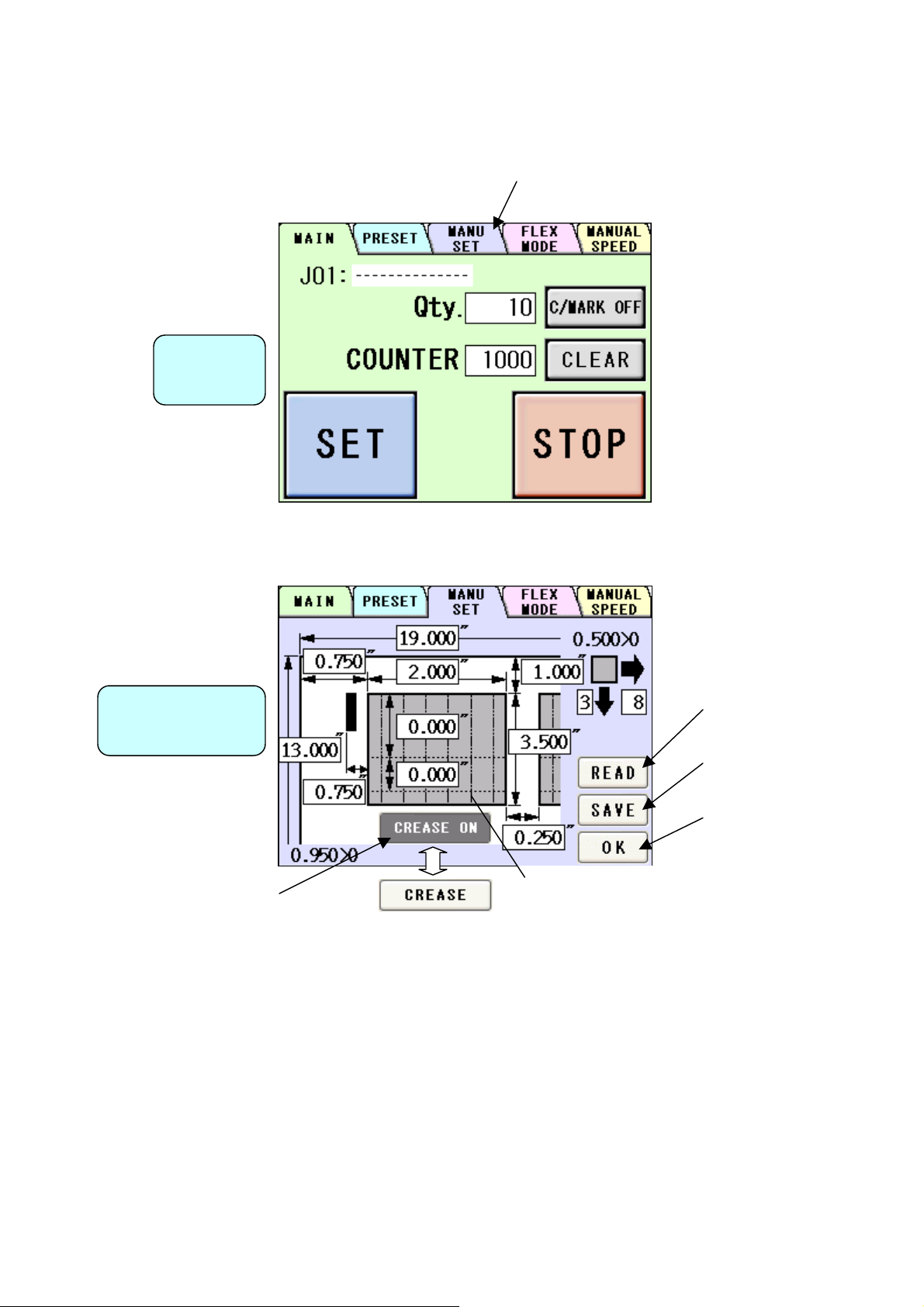
(4) Free entry
① Press MANU SET.
Operation
Screen
② The operation is almost the same as (3)-④.
Cutting Pattern
Correction Screen
Move to User Program
Selection Screen
Move to User Program
Selection Screen
Confirm cutting
pattern and move to
Operation Screen
It turns automatically into
CREASE ON when you input the
measure of any crease pos.
Line is the number of
crease you make on
a sheet.
27
Page 29

j
prog
(5) User program retrieval (MANU SET)
① 60 user program can be registered.
② Press the button of the name you wish to retrieve.
User Program
Selection Screen
③ Confirm the details of the program for retrieval.
User Program
Detail Screen
Move to the previous
10 program
Move to the next 10
program
Return to Cutting Pattern
Correction Screen
Move to the previous
ram
Enter the number to
ump to it
Move to the next program
Retrieve user program
and go to Operation
Screen
Return to User Program
Selection Screen
28
Page 30

r
(6) User program registration (MANU SET)
① 60 user program can be registered.
② Press the button in which you wish to make a registration.
User Program
Selection Screen
③ Confirm the program stored in the selected place.
Enter the name fo
registration
Move to the previous
10 program
Move to the next 10
program
Return to Cutting Pattern
Correction Screen
Copy
Currently registered name
Double Click to make a
copy of input name.
User Program
Detail Screen
Delete confirmation
Move to the previous
program
Enter the number to jump
to it
Move to the next program
Overwrite confirmation
Return to User Program
Selection Screen
29
Page 31

Uppercase/lowercase
switching
Cancel the entry
and return
Finalize the registration name
For overwriting and
move to Cutting Pattern
Correction Screen
Return to User Program
Detail Screen
Delete and move to
User Program Detail
Screen
Return to User Program
Detail Screen
30
Page 32

A
G
(7) FLEX entry
① Press FLEX MODE.
Operation
Screen
② This input screen allows you to freely select the guillotine or the crease up to 20 pitches
for the paper of non-identical size unacceptable in the MANUSET screen, paper with
special cutting patterns, and paper completely passing through.
Cutting Pattern
Correction Screen
D
E
F
HC
Solid line is the number of
guillotine you make on a
sheet.
I
Chain double-dashed line
is the number of creases
you make on a sheet.
B
Move to User Program
Selection Screen
Move to User Program
Selection Screen
Confirm cutting
pattern and move to
Operation Screen
Move to Cutting Pitch
Correction Screen
31
Page 33
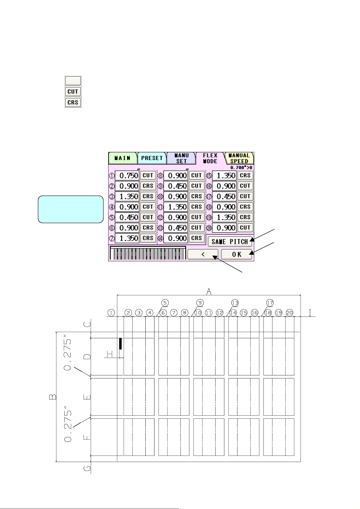
③ This screen allows you to input each pitch from No. 1 to No. 20. The adjacent switches
are used for selecting no operation, guillotine, or creaser. Every time the switch is
pressed, the selected operation changes.
:No operation
:Guillotine
:Crease
④ If the pitch of 0.000” is input, all the pitches after that one are corrected to 0.000” (no
operation).
⑤ Pressing SAME PITCH copies the No. 1 pitch and its relevant operation to No. 2 to No.
20 pitches.
Cutting Pitch
Correction Screen
Confirm cutting
pattern and move to
Operation Screen
Move to Cutting Pattern
Correction Screen
32
Page 34
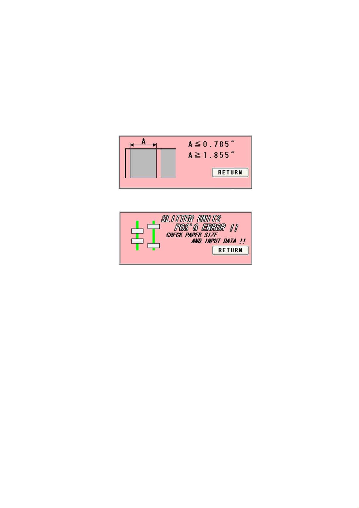
⑥ When letting the paper pass through completely (when passing only via the perforator or
when using as the feeder), input the paper size for A and B, and the same dimension as B
for D. Input “0” for all the remaining dimensions.
⑦ Make sure for the first cut line must be 0.785” or shorter from the edge of the paper. If
you want to cut off 0.785” or more, please cut off 0.785” or less at first and then cut off
again and again. If you try to move the slitter cut line at 1.855 or more position, the slit
will be ejected on Paper ejection table instead of waste box. If you try to move the slitter
between 0.785” and 1.855” from the edge of the paper, error occurs.
⑧ If you try to move the slitter to the position that is physically impossible, the error occurs.
33
Page 35
j
prog
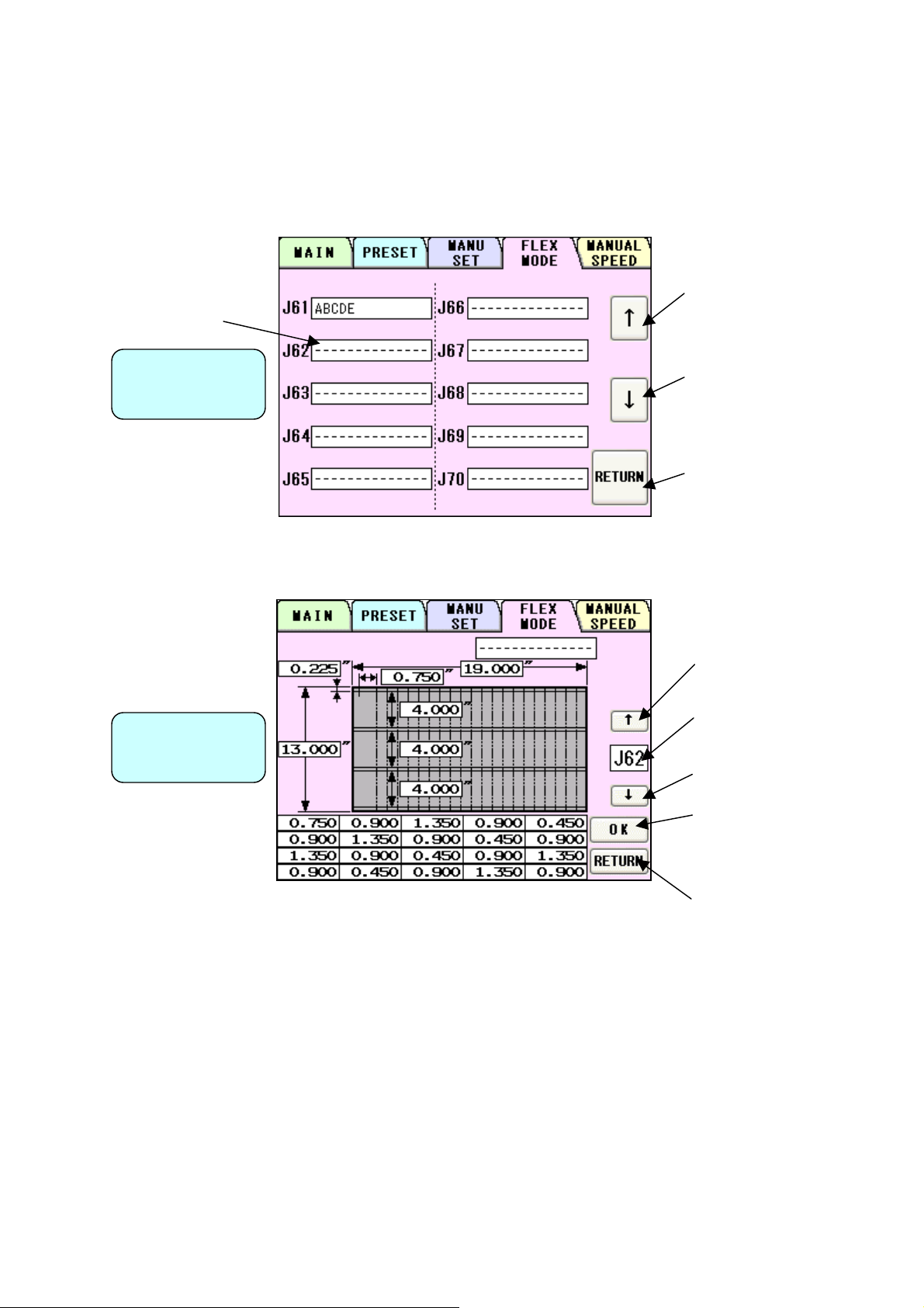
(8) User program retrieval (FLEX MODE)
① 30 user program can be registered.
② Press the button of the name you wish to retrieve.
User Program
Selection Screen
③ Confirm the details of the program for retrieval.
User Program
Detail Screen
Move to the previous
10 program
Move to the next 10
program
Return to Cutting Pattern
Correction Screen
Move to the previous
ram
Enter the number to
ump to it
Move to the next program
Retrieve user program
and go to Operation
Screen
Return to User Program
Selection Screen
34
Page 36

r
(9) User program registration (FLEX MODE)
① 30 user program can be registered.
② Press the button in which you wish to make a registration.
User Program
Selection Screen
③ Confirm the program stored in the selected place.
Enter the name fo
registration
Move to the previous
10 program
Move to the next 10
program
Return to Cutting Pattern
Correction Screen
Copy
Currently registered name
Double Click to make a
copy of input name.
Move to the previous
program
User Program
Detail Screen
Enter the number to jump
to it
Move to the next program
Delete confirmation
Overwrite confirmation
Return to User Program
Selection Screen
35
Page 37

Uppercase/lowercase
switching
Cancel the entry
and return
Finalize the registration name
For overwriting and
move to Cutting Pattern
Correction Screen
Return to User Program
Detail Screen
Delete and move to
User Program Detail
Screen
Return to User Program
Detail Screen
36
Page 38

(10) Setting of slitter and feed table
① By pressing SET, the feed table will be lowered to the bottom dead point and the slitter will
move to the operating position.
② The display will change from SET to START upon completion.
Operation
Screen
(11) Operation number cancellation
① The total number of processed sheets are counted. Press CLR and hold to clear the
number. You can change the
Total number.
Operation
Screen
Total number of
operated sheets
You can make a little adjustment on
Total number.
37
Page 39

(12) Manual operation and Speed Change
① Press MANUAL SPEED.
Operation
Screen
② Use it when operating manually.
③ There are eight feeding speed levels. The currently selected speed level is inverted to
black. Thick paper should not be fed at higher speeds. Please slow the speed down if
sheet stops with noise associated.
The feeder will rotate in
reverse
The guillotine will
operate once.
The feeder will
rotate.
The creaser stops at
the top dead point.
Manual Operation
Screen
38
The creaser stops at
the bottom dead
Move to Adjust Screen
☞
4-(4) If the cut measurement
does not match the input value
Page 40

④ To avoid double feed or skew feed, adjust PAPER FEED WORK TIME and volume of AIR
BLOW.
SHORT LONG
Double feed:
PAPER FEED
WORK TIME
more likely to occur
Skew feed:
less likely to occur
0.5s~5.0s
Double feed:
less likely to occur
Skew Feed:
more likely to occur
BLOW OFF SHORT BLOW LONG BLOW
Double feed:
less likely to occur
Skew feed:
more likely to occur
AIR BLOW
Double feed:
more likely to occur
Skew feed:
less likely to occur
As a recommended default setting, PAPER FEED WORK TIME should be 0.0 seconds
and AIR BLOW should be LONG BLOW.
⑤ If double feed is not detected, select D FEED OFF.
⑥ If double feed is detected, detection will be affected by the paper thickness and print color.
Select a more suitable threshold value from among HIGH, MID, and LOW. Generally, it is
more effective to set to HIGH for thin or white paper, and to LOW for thick or dark paper.
Double feed detection is performed based on the thickness of the first sheet. It is not
effective at all if the first sheet is doubly fed.
D FEED HIGH: Because of a high threshold value for double feed detection, the
machine may react depending on the type of print and paper thickness,
even if the paper is not doubly fed.
D FEED MID: Because of a middle threshold value for double feed, the machine may or
may not react, depending on the type of print and paper thickness.
D FEED LOW: Because of a low threshold value for double feed, the machine may not
react, depending on the type of print and paper thickness, even if the
paper is doubly fed.
(13) Cut mark on/off selection
Operation
Screen
Select C/MARK ON to
use cut marks. Select
C/MARK OFF for not
using cut marks.
39
Page 41

(14) Automatic operation
① Set the number of sheets for operation. The machine will automatically stop on reaching
the set number. Enter “0” for continuous operations.
User program job number and job name you have retrieved is displayed.
Operation
Screen
Enter the number of
sheets for operation.
(Batch Counter) Enter “0”
for continuous
operations.
② Press START to start an automatic operation. The display will change to RUNNING.
③ Press STOP and the machine will make an EMERGENCY stop even if the operation is
underway.
④ Press END if you wish to stop the machine when the current sheet is completed. The END
sign will blink and the machine will automatically stop upon completion of the work.
Number of sheets
completed
Operation
Screen
40
Page 42
4. Instructions for use
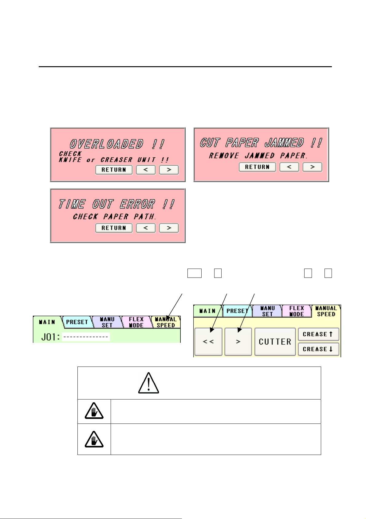
(1) If the machine stops during operation
① If the machine stops during operation due to an error such as a paper jam and
overloading, paper may still be left in the machine.
② In such a case, the paper must be removed by manual operation, as continuing to operate
it may cause a mechanical failure
③ Press MANUAL SPEED, and then press << or > from the screen, or press < or >
from the error screens as shown above to move the feeder for paper ejection.
Caution
Avoid contacting any rotating object.
Otherwise, injury could occur.
Don't bring a hand, face, hair, sleeves of clothes and
the like close to the rotating parts of the machine.
There is a danger of receiving an injury.
41
Page 43

(2) If Paper scrap remains on the machine
A
① When the paper jams near the stacker panel or when maintenance work is done, the
stacker panel can be opened.
② Shift the right and left lock levers of the stacker panel to the inner side, and pull the upper
part by hand to open.
③ Pick up paper scraps with
④ With the stacker panel opened, the machine cannot be operated, resulting in Cover open
error.
⑤ To reposition the stacker panel, just close it.
Stacker panel
Lock lever
⑥ If the paper scrap remains in cutter cover.
If Paper scrap remains under the Cutter cover of the machine, turn off the machine and take
off thumb screw to remove the anti-static brush setting plate. After removing plate there will
Tweezers and take them away.
Lock lever
be a space. Push the paper t scrap down with Waste ejector, which comes with machine.
Waste ejector
Thumb screw
Caution
Power it off. Otherwise,
Injury could occur.
nti-static Brush Setting Plate
Cutter cover
42
Page 44
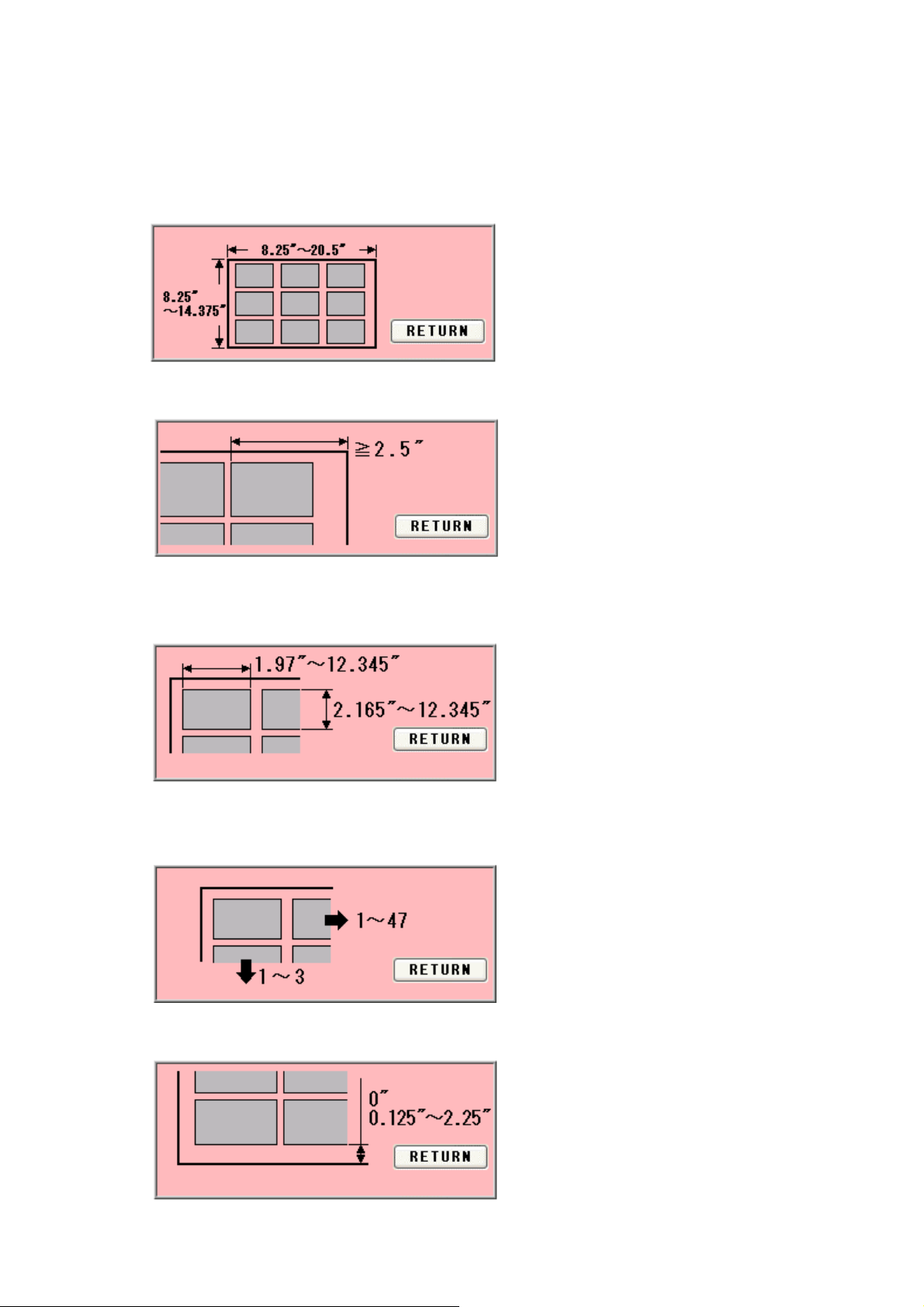
(3) Details concerning errors
① Paper size error
Correct the paper size to fit in the value range below.
② Final cutting measurement error
Correct the final cutting measurement to exceed the value specified below.
③ Cutting measurement error
Correct the cutting measurement to fit in the value range below. The maximum value is
subject to change depending on the entered paper size.
④ Cut piece number error
Correct the number of cut pieces to be in the value range below. The maximum number of
pieces is subject to change depending on the operation.
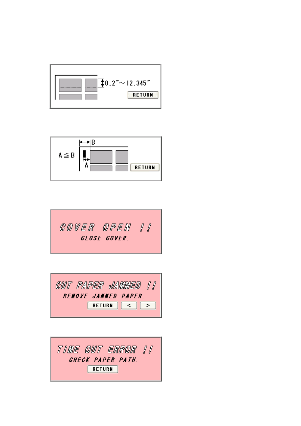
⑤ Bottom margin error
Correct the bottom margin to fit in the value range below.
43
Page 45
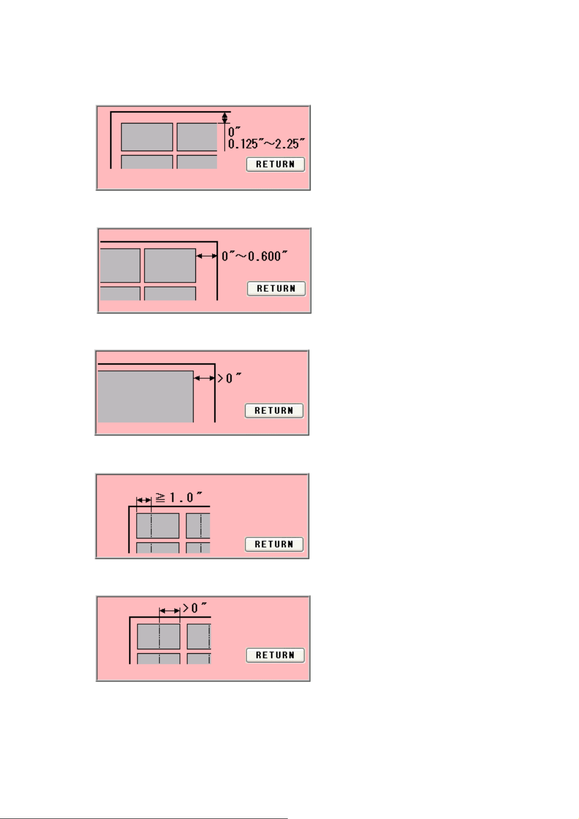
⑥ Top margin error
Correct the top margin to fit in the value range below.
⑦ Back margin error (MANU SET)
Correct the back margin to fit in the value specified below.
⑧ Back margin error (FLEX MODE)
Correct the back margin to fit in the value specified below.
⑨ Crease front margin error
Correct the crease front margin to exceed the value specified below.
⑩ Crease back margin error
Correct the crease back margin to exceed the value specified below.
44
Page 46
⑪ Perforation location warning
Correct the perforation location to fit in the value range below. The maximum value is
subject to change depending on the entered paper size.
⑫ Leading edge margin and cut mark margin warning
Correct the measurement so that the leading margin becomes larger than the cut mark
margin.
⑬ Cover open error
Safety cover or Stacker panel might be open.
Make sure to close the Safety cover and Stacker Panel is closed.
⑭ Paper jam error
Paper remains inside the machine. Remove the paper.
⑮ Timeout error 1
Paper was not fed within a set time period. Check the paper feeder.
45
Page 47
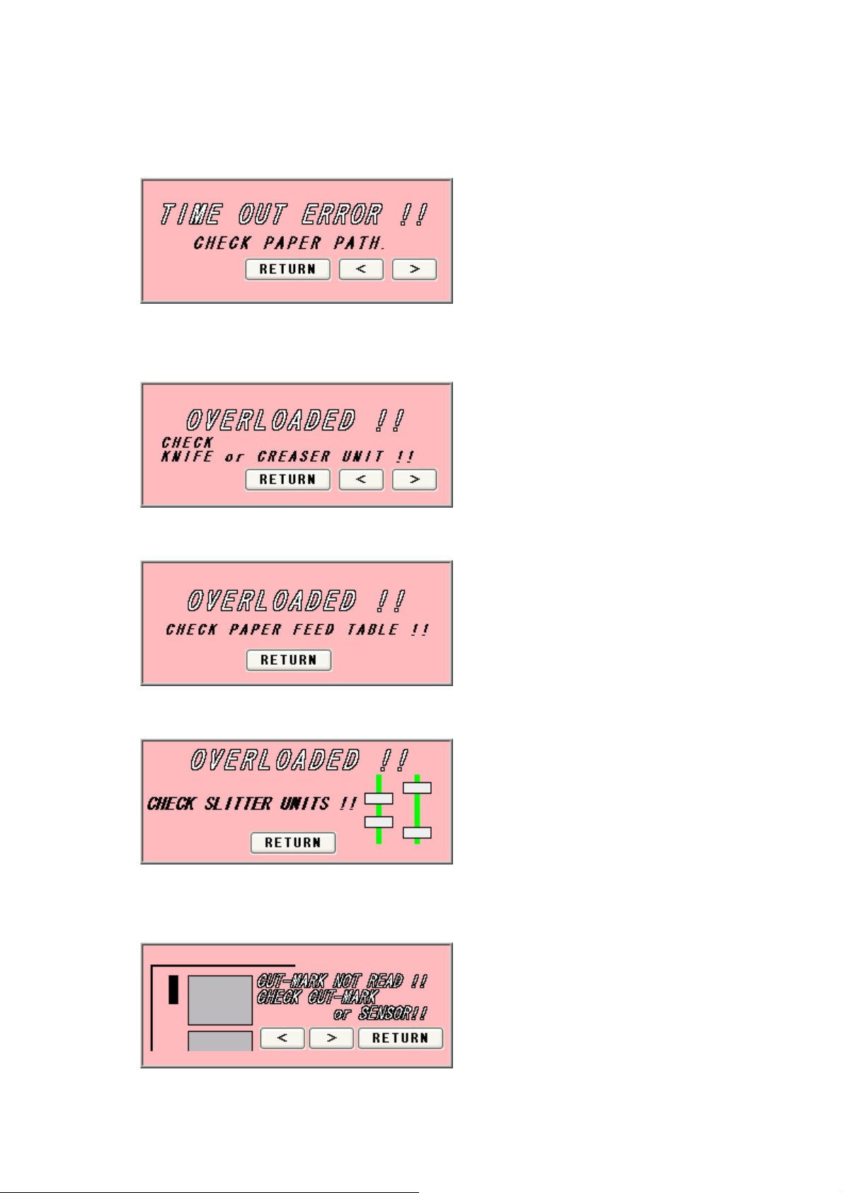
⑯ Timeout error 2
Paper did not pass through within a set time period. Remove the paper remaining inside
the machine.
⑰ Overload error 1
Cutting or creasing did not complete within a set time period. Remove the paper
remaining inside the machine.
⑱ Overload error 2
An overloading error occurred at the feed table. Check the feed table.
⑲ Overload error 3
An overloading error occurred at the slitter. Check the blinking slitter.
⑳ Cut mark detection error
Cut mark was unable to be detected. Check the cut mark. Eject the paper inside the
machine.
46
Page 48

Double feed detection error
Double feed detected. Check the paper or paper path.
Slitter units positioning error
Slitter position is out of valid range. Check paper size and input data.
Serial communication error
Communication with the touch panel is not possible. Turn off the power, and turn it on
again after 5 seconds or longer.
Servo motor error
Servo motor error detected. Turn off the power, and turn it on again after 5 seconds or
longer.
47
Page 49

Data aren’t updated error
This error message appears as a warning when proceeding to another screen without
saving the corrected dimensions in the MANU SET or FLEX MODE screen. Press OK if
you want to proceed to the other screen; otherwise, press RETURN.
FLEX MODE input error
This error results when the three input values shown in the following figure are “0” or
lower at FLEX MODE time.
48
Page 50

A
A
G
(4) If the cut measurement does not match the input value
① If Measurement A is different: When the input value is 0.200” and the actual cut
measurement is 0.175”, input +0.025”; input -0.040” when the actual cut measurement is
0.240”. ※
② If Measurements B, C, or D are different: When the input value is 3.500” and the actual
cut measurement is 3.560”, input -0.060”; input +0.080” when the actual cut measurement
is 3.420”. ※
③ If Measurement E is different: When the input value is 0.600” and the actual cut
measurement is 0.620”, input -0.020”; input +0.050” when the actual cut measurement is
0.550”. (You can input ±0.400” at the most)
④ If Measurement F (crease location) is different: When the input value is 2.000” and the
actual crease measurement is 2.250”, input -0.250”; input +0.100” when the actual crease
measurement is 1.900”. (You can input ±0.400” at the most)
⑤ If Measurement G is different: When the input value is 0.400” and the actual cut
measurement is 0.450”, input –0.050”; input +0.100” when the actual cut measurement is
0.300”. (You can input ±0.400” at the most)
⑥ Use H and I for magnificent adjustment. If the printed image is bigger or smaller than the
one you designate, you can adjust cutting length to fit the printed measurement with this
magnificent adjustment.:
4.080”, input 0.980 (4.000” ÷ 4.080”); input 1.010 (4.000” ÷ 3.960”) when the actual
cut measurement is 3.960”. When this measurement is corrected, Measurements E, F
and G will need to be corrected as well. Refer to ③–⑤above and make corrections. (H
must be from 0.500 times to 2.000 times and I must be from0.800 times to 1.200times)
※:If you press OK after you input values into A, B, C and D, those values will be added to
each total measurements which are circled on the image below. Then, A, B, C and D will
be reset to 0.000. You can change the measurement by 0.002”. Each adjustment should
be within±0.080” at one time. If the gap is more than ±0.080”, repeat the process
until the desired measurement is reached.
When the input value is 4.000” and the actual cut measurement is
Resets to the factory
setting
djust
Screen
F
E
BC
Total measurement that
has been changed A, B,
C, and D.
I
DH
49
Correct the
measurement and
Return to Manual
Operation Screen
Return to Manual
Operation Screen without
making corrections
Page 51

5. Product specifications
Specifications
Slitter 4 sets (6 slitter blades)
Creaser 1 set (5-level manual crease depth adjustment)
Perforator 2 sets
Number of guillotine or creasing MAX48times / sheet
Paper size (depth direction)
Paper size (feed direction)
Finish size
Paper weight
Maximum paper curl size
Paper type Offset, Coat, UVcoat, Glossy, Laminate
Paper feeding method Air Suction
Input tray capacity MAX4.000”
Speed
Machine dimensions
Net weight 452lbs. (205Kg)
Power supply
Power consumption 400W
8.25” (A4 short) ~14.375” (B3 short)
8.25” (A4 short) ~20.500” (B3 long)
MIN1.97”W×2.165”D
32 lbs (Bond) – 130 lbs (Cover stock)
[120-350g/㎡]
±0.125”
MAX 12 sheets per minute
(in case of eight cut from SRA3 to Postcard)
35.8” W ×31.5” D× 42.9” H
(Occupancy area: 68.5” W×31.5” D×60.6” H)
Single phase 110-120VAC, 50/60Hz,
3.6A-3.3A
Use temperature 23 to 104°F (-5 to 40°C)
Preservation temperature -13 to 149°F (-25 to 60°C)
Use temperature humidity
Preservation humidity
Use the uplands
One’s tolerance level
Over voltage category
Pollution degree Degree 3 according to IEC60664-1
Category Ⅲ according to IEC60664-1
50
45~85%RH
25~100%RH
~1000M
110~120V +6%, -10%
Page 52

51
Page 53

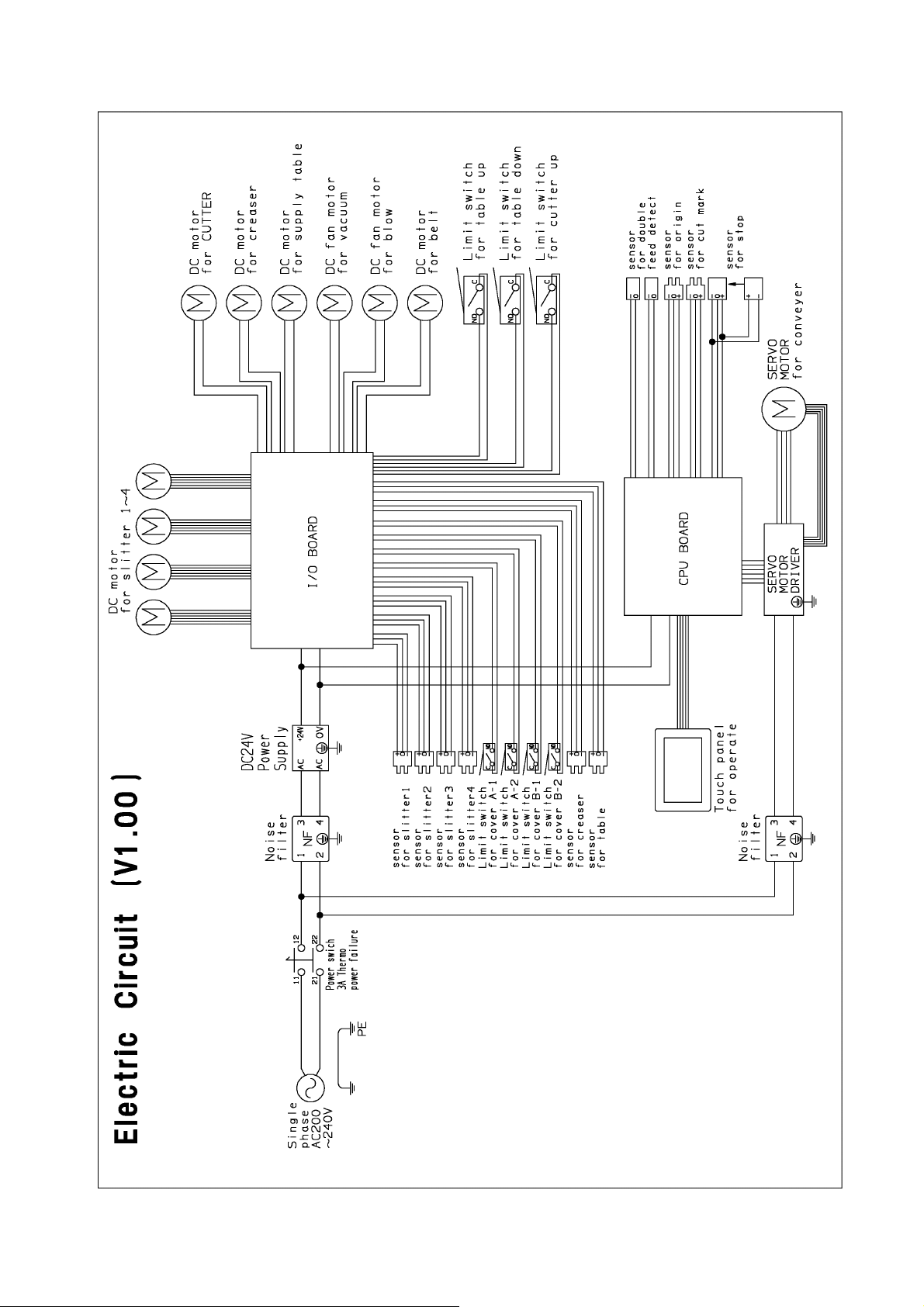
6. Equipment, Electric circuit and parts
52
Page 54
53
Page 55

54
Page 56

7. Ordering consumables, etc.
When ordering consumables or parts, be sure to specify the machine model.
55
Page 57

56
Page 58

OPERATION MANUAL
Keep this “Operation Manual” at an appointed place with care so that it
may be available whenever required.
If this “Operation Manual” is stained or lost, make contact with the
distributor or our salesman or customer service section to ask for a new
operation manual after making sure of its contents.
UCHIDA YOKO CO., LTD.
57
 Loading...