

Page 1
Stapler-Folder Model 82
Operator Manual
February 2003
Part No 76174
Page 2

Page 3

1. Introduction
2. Getting to know the Model 82
2.1 Main components
2.2 The control panel
3. Operating and finishing modes
3.1 The operating modes
3.2 The finishing modes
3.3 Jam indications
Table of contents
4. Operator instructions
4.1 Connecting the Model 82 to a collator
4.2 Setting / Changing paper size
4.3 Adjusting the St acker
4.4 Beginning the production
5. Maintenance
5.1 Replacing the Staple cartridge
5.2 Removing Stapler head / clearing staple jam
5.3 Lubrication of Clinchers and Stapler Head
5.4 Cleaning of Fold rollers
5.5 GFI function test and resetting
6. Troubleshooting
7. Specifications
Stapler Folder Model 82 Operator Manual
T10136
i
Page 4

1. Introduction
This operator manual describes how to operate the Stapler-folder
Model 82 on-line together with collator Models 300/400, Model 100 or
as a stand alone unit.
Operational safety
Attention to the following notes ensures the continued safety operation of your equipment.
Always connect the equipment to a properly
grounded power source receptacle. In doubt,
have the receptacle checked by a qualified
electrician.
WARNING: Improper connection of the equipment grounding conductor can result in electrical shock.
Always follow all warnings marked on, or supplied with, the equipment.
Always locate the equipment on a solid support
surface with adequate strength for the weight of
the machine.
Always exercise care in moving or relocating
the equipment.
Always keep magnets and all devices with
strong magnetic field away from the machine.
Never use a ground adapter plug to connect
the equipment to a power source receptacle
that lacks a ground connection terminal.
Never attempt any maintenance function that is
not specifically described in this documentation.
Never remove the covers or guards that are
fastened with screws.
Never install the unit near a radiator or any
other heat source.
Never override or “cheat” electrical or
mechanical interlock devices.
Never operate the equipment if you notice
unusual noises or odors. Disconnect the power
cord from the power source receptacle and call
your customer service engineer to correct the
problem.
Stapler Folder Model 82 Operator Manual
T10136
1-1
Page 5
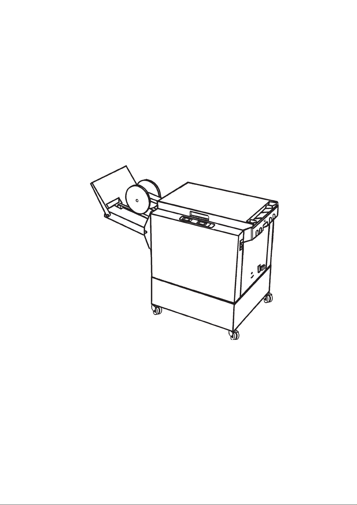
2. Getting to know the Model 82
T ake a few minutes to become familiar with the main components
of the Model 82.
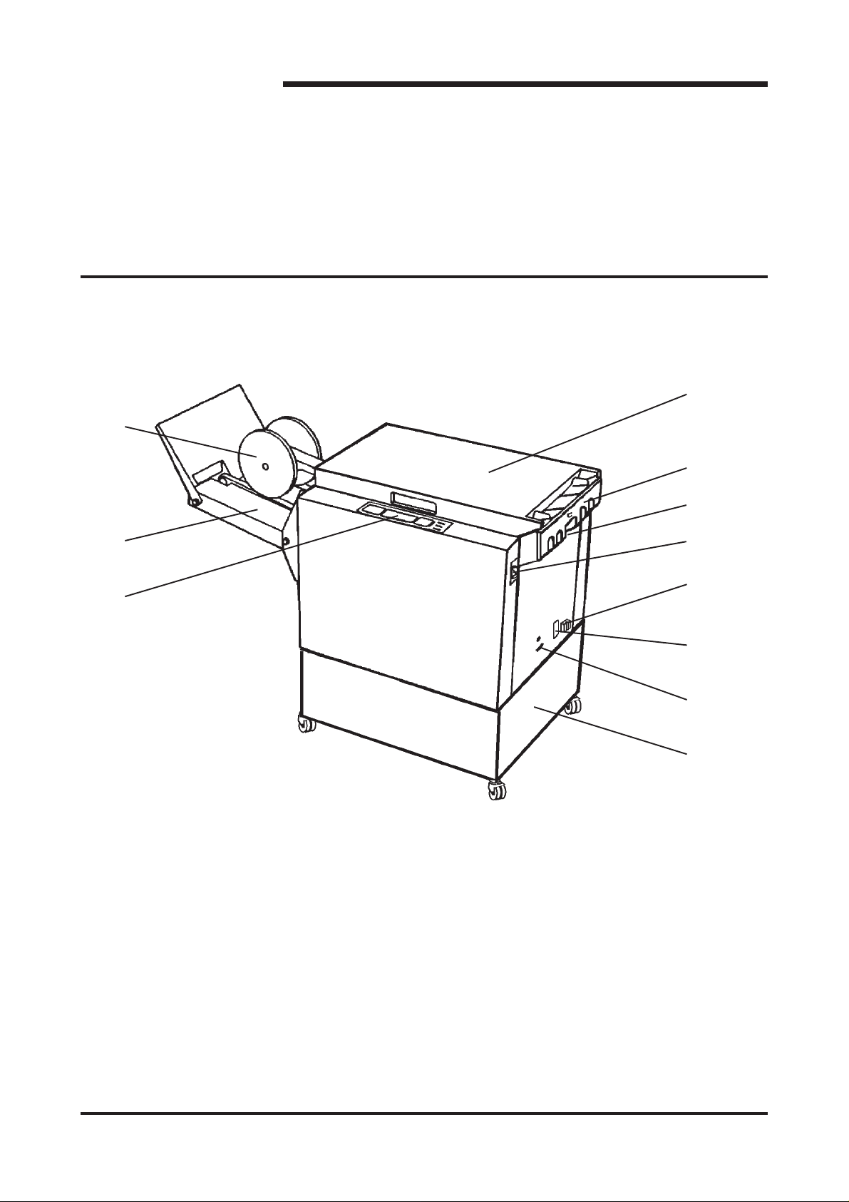
2.1 Main components
1
4
5
6
2
3
1. Output wheels 7. Power switch
2. Belt stacker 8. Ground fault interruptor (GFI )
3. Control panel 9. Power cord receptacle incl. fuses
7
8
9
10
11
4. Top cover 10. Connection cable outlet
5. Docking assembly 1 1. Base
6. Back jogger adjustment screw
Stapler Folder Model 82 Operator Manual
T10136
2-1
Page 6
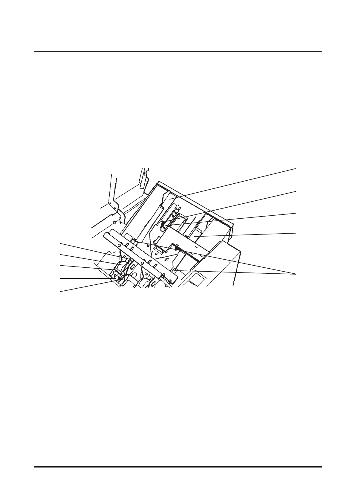
2.1 Main components cont.
When setting up the Model 82 or performing maintenance it is
sometimes required to move internal components of the machine.
T ake a few minutes to become familiar with these components.
6
7
1
2
3
4
5
1. Stapler head 6. Rear Side guide
2. Staple cartridge 7. Back jogger
8
9
10
3. Cartridge locking lever 8. Scale, length adjustment
4. Stapler release latch 9. Front Side guide
5. Staple detection lead 10. Release handle, Side guide
Stapler Folder Model 82 Operator Manual
T10136
2-2
Page 7

2.2 Control panel
1
23 645 7 8910
11 12 13 14 15
1. Auto mode indicator 9. Stacker full indicator
2. Manual mode indicator 1 0. Staple(s) missing indicator
3. Staple and fold mode indicator 1 1. Manual / Auto mode button
4. Fold mode indicator 12. Program select button
5. Edge stapling mode indicator 13. Run / Adjustment mode button
6. Run mode indicator 14. Length adjustment button, decrease
7. Adjustment mode indicator 15. Length adjustment button, increase
8. Paper jam indicator
Stapler Folder Model 82 Operator Manual
T10136
2-3
Page 8

3. Operating and finishing modes
The Model 82 can be operated in several combinations of modes.
These modes are two operating modes and three finishing
modes. In this section we will explain the different modes and how
they are selected.
3.1 The operating modes
The two operating modes are:
1. Manual mode
Select Manual mode if operating the Model 82 as a stand alone
unit, for hand feeding.
The Manual mode is selected when the MAN LED is lit.
Press the Manual / Auto mode button to change operating mode.
2. Automatic mode
Select Automatic mode if operating the Model 82 together with a
collator as an on-line system.
The Automatic mode is selected when the AUTO LED is lit.
Press the Manual / Auto mode button to change operating mode.
Note: If in manual mode when the on-line connected collator starts, the
mode will automatically switch from Manual to Automatic mode, to
prevent interruptions.
3.2 The finishing modes
The three finishing modes are:
1. Edge stapling
When selecting this mode by pressing the Program select
button the set will exit at the lower output area. A delivery tray for
edge stapled sets is available, part no. 750004.
If a Trimmer is installed to your Model 82, remove the scrap p aper
bin to allow the edge stapled sets to enter the delivery tray which
is integrated in the base of the T rimmer.
2. Fold only
When selecting this mode by pressing the Program select button,
the stapler action is switched off and the folded set will exit at the
upper output area onto the belt stacker.
3. Saddle stapling and fold
When selecting this mode by pressing the Program select button,
the stapled and folded sets will exit at the upper output area onto
the belt stacker .
Stapler Folder Model 82 Operator Manual
T10136
3-1
Page 9

3.3 Jam indications
1. Staple(s) missing indicator
The Staple(s) missing indicator is illuminated when a set is
missing one or two staples. The Model 82 will automatically
stop the on-line system when this indicator LED is lit.
Upon indication after loading a new staple cartridge, open
and close the T op cover . The Model 82 will now cycle and
advance staples on the same set for a maximum of 5
stapling cycles or until staples are resumed. Replacing the
staple cartridge is described in section 5.
2. Stacker full indicator
The Stacker full indicator is lit when the belt st acker or the
delivery tray is full. Remove the finished sets. As soon as the
stacker full sensor is clear the indication will go off. The
Model 82 will automatically stop the on-line system when this
indicator LED is lit. All sets already fed from the Collator will
be processed until full stoppage.
3. Paper jam indicator
The Paper jam indicator is illuminated when an operation in
the Model 82 is not done within the preset time. Open the
top cover and remove the jammed sets reachable, close the
top cover and the Model 82 will automatically purge
remaining jammed sets. Model 82 will automatically stop the
on-line system when this indicator LED is lit.
Stapler Folder Model 82 Operator Manual
T10136
3-2
Page 10

4. Operator instructions
4.1 Connecting the Model 82 to a Collator
Communication
box
15-pin
jack
25-pin
jack
Studs
9-pin
connection
cable
T ermination
plug
1. Make sure the main power is switched off on both machines.
For 300/400 series collator: Plug the Connection cable
between the jack on the stacker side of the Collator to the 25pin jack on the Model 82.
For Model 100 collator: Plug the 9-pin Connection cable
between the collator and the upper 9-pin jack of the
Communication box. Plug the other connection cable between
the 15-pin jack of the Communication box to the 25-pin jack
on the Model 82. Connect a termination plug in the lower 9-pin
jack of the Communication box. Connect another termination
plug in the Collator.
2. Connect the Power cord to the receptacle on the Model 82
and into the wall outlet. Switch on the Model 82 and Collator.
3. Move the Model 82 infeed end to the outfeed end of the
Collator. The docking assembly will automatically lock onto
th e Collator when studs of the Collator enters the Model 82
A4 (8.5”) or A3 (1 1”)-position openings. The green mark on
the rear side guide corresponding to green strip on the
Collator helps you docking in the correct position.
Adjustment
knob for
odd sizes
A3 / 1 1”
A4 / 8.5”
4. The docking assembly is released by pressing the green area
on the side of the assembly .
5. If running an odd paper size, loosen the knob on the lower
side of the docking assembly . Move the Model 82 sideways
so the green mark on the rear side guide aligns with the green
strip on the Collator.
Normal position of the docking assembly is indicated by a
centring notch.
Stapler Folder Model 82 Operator Manual
T10136
4-1
Page 11

4.2 Setting / Changing paper size
1. Select program on the Control panel:
Edge stapling, only Folding or S tapling/Folding.
2. Open the top cover and press the Run/Adjustment button to
access the Sheet length adjustment buttons on the Control
panel.
Program
select
button
Run/Adjustment button
Run/Adjustment button
Sheet length
adjustment
buttons
3. Adjust the front and rear Side guide to the paper width that
will be used. Adjust the side guides by squeezing at the
green marks on the release handles.
4. Release the Docking assembly to shift the positioning of the
Model 82 in order to align the green stripe on the collator
with the green mark on the rear Side guide.
5. Adjust the sheet length slightly larger than the paper size
being used.
Close the top cover .
6. Feed one test set into the Model 82.
7. Open the top cover and adjust the sheet length so that the
trail edge of the set just about touches the backjogger .
8. Check that the set is not squeezed so it buckles between the
side guides. The side guides should just about touch the set.
Fine adjust the Side guides if necessary .
Close the top cover and push the Run / Adjustment button to
exit the Adjustment mode. The set will be processed though
the machine.
Stapler Folder Model 82 Operator Manual
T10136
4-2
Page 12

4.3 Adjusting the Stacker
The output wheels can be positioned in four different positions.
1. The A4 / 8.5 x 11” position.
Output wheel
Coveyor belt
Use this position when making booklets from A4 ( 8.5 x 1 1”)
size paper .
2. The 8.5 x 14” position. ( N/A on A4 / A3 Machines)
Use this position when making booklets from 8.5 x 14” size
paper.
3. The A3 / 11 x 17” position.
Use this position when making booklets from A3 ( 1 1 x 17”)
size paper .
4. The outermost position.
Use this position when storing the equipment or for easier
access to the delivery tray when edge stapling. This allows
you to fold the Belt stacker to an upright position.
T o change the position of the Output wheels:
1. Place the wheels on the conveyor belts .
2. Grasp the Output wheels and turn them towards decired
position. The Output wheels should contacting the belts when
shifting position.
End plate
T o change the position of the End plate:
1. Grasp the End plate and pull the knob.
2. Tilt the end plate to decired angle and release the knob.
The stacker should normally be straight when connected directly
Angle
block
Knob
to Model 82. If St acker is connected to the Trimmer it is
recommended to angle the stacker.
T o change the angle of the S tacker:
1. Lift the St acker to an angle.
2. Turn the angle blocks and release the stacker .
4.4 Beginning the production
1. Set operating mode to Manual or Automatic (according to
3.1).
2. Set the finishing mode (according to 3.2).
3. Make the paper size adjustments (according to 4.2 and 4.3).
4. Ensure that the Model 82 is in Run mode and:
5a. If running in Manual mode:
Start hand feeding the set.
5b. If running in Auto mode:
Set up the Collator, run a test set and st art the production.
Stapler Folder Model 82 Operator Manual
T10136
4-3
Page 13

5. Maintenance
5.1 Replacing the Staple cartridge.
Y ou may remove and replace the S taple cartridge while the
Stapler head is in place within the Model 82. The Staple cartridges contain approximately 5000 staples per cartridge and can be
replaced as often as necessary .
1. If the staples missing indicator is illuminated, open the Top
cover and remove eventual jammed sets.
NOTE! One set must be left in stapling position (see item 8 below).
2. Raise the red handle on the Staple cartridge Locking lever .
3. Remove the Staple cartridge from the Stapler head by sliding
it to the left.
4. If the cartridge is empty , discard it and replace it with a new
one. Before replacing the cartridge, pull 25 mm (1 inch) of
staples out of the cartridge and tear the staples downward
against the staple tear line. The staple tear line is indicated by
an arrow on the side of the cartridge.
5. If there has been a staple misfeed, and if it is necessary to
remove the cartridge in order to clear the misfeed,
pull 25 mm (1 inch) of staples out of the cartridge and tear the
staples downward against the staple tear line before
reinstalling the cartridge.
6. Insert the cartridge into the Stapler head with the end of the
staples facing toward the head of the stapler mechanism.
Push it in firmly .
7. Hold the Staple cartridge firmly in place and push down the
cartridge locking lever . Close the T op cover .
8. The Model 82 will automatically cycle and advance staples
until both stapler heads are driving staples for a maximum of 5
stapling movements.
If staples are not resumed after 5 stapling cycles, the staple
indication will come on. This indicates that the staple cartridge
was not loaded sucessfully . Repeat this procedure.
Stapler Folder Model 82 Operator Manual
T10136
5-1
Page 14

5.2 Replacing the Stapler head / Clearing st aple jam
1. Switch the power switch to OFF (0) position. Open the Top cover
on the Model 82. Disconnect the Staple indication lead (1) from
the socket.
2. Hold the Stapler head in place, press the Release lever (2) to
release the rear end of the stapler head and lift up this end.
3. Lift out the head, allowing it to rotate around the front end. The
Stapler assembly is spring loaded and will follow the rotation of
2
1
the St apler.
4. Remove stapler cartridge. Look inside stapler head to locate
jammed staples by eject point. Remove staples if any.
5. Position the Stapler head over the edge of a firm surface (for
example, the top of a table or the Model 82).
6. While securely holding the head, actuate the Stapler up and down
through full travel. Perform this operation first without staple
cartridge then with staple cartridge. Repeat this a few times to
ensure that the staples are ejected at each down movement.
NOTE: Actuation must be performed without excessive force. If binding
occurs there may be broken staples inside. Dis-assembly may be
required.
7. To reinstall the Stapler head, insert the pin at the top of the stapler
head into the St apler retraction swing arm (3).
8. While rot ating the Stapler head, insert the pin located at the rear
3
end of the St apler head into the slots in the frame of the Stapler
head assembly. Press down the rear end of the Stapler head until
the release lever (2) snaps into place, locking the S tapler head in
position.
9. Press down the front end of the Stapler head until it snaps in
position under the frame assembly.
10. Reconnect the Staple indication lead (1).
Stapler Folder Model 82 Operator Manual
T10136
5-2
Page 15

5.3 Lubrication of Clinchers and Stapler Head
The Clinchers must be oiled every 20 000 cycles.
When lubrication is due, out of staple indicator flashes.
1. Put a couple of drops of oil in each clincher.
T o get rid of excessive oil:
2. Push down each clincher lever a couple of times.
3. Push down clincher lever while wiping off excessive oil
using a dry cloth.
4. Run a few blank booklets.
Oil
Sheet length
adjustment
buttons
Push
Push
When clinchers have been lubricated, the flashing staple indicator
must be reset:
5. Press and hold both sheet length adjustment buttons
simultaneously.
The staple indicator will first go from flashing to on.
After 4 seconds the indicator will go off.
6. Release the buttons.
The stapler head drive post on each stapler head must be
lubricated every 20 000 cycles.
1. Remove the stapler head according to section 5.2.
2. Put a couple of drops of oil on each side of the drive post.
Oil
3. Cycle the stapler head a few times before installing it again.
Oil
Stapler Folder Model 82 Operator Manual
T10136
Page 16

5.4 Cleaning of Fold rollers.
The Fold rollers need to be cleaned regularly when in use. How
often this should be done is depending on what kind of paper and
print that is used in the unit.
1. Open the T op cover . Clean the accessible areas of the Fold
rollers with a rubber reactivator liquid.
Clean from both the inside of the unit and through the output
opening.
2. Close the T op cover and run one set of two sheet s through
the unit.
3. Repeat step 1 and 2 until rollers are cleaned
(approximately 2-3 times).
5.5 GFI function test and resetting.
WARNING: DO NOT use the Model 82 if the following test fails.
No additional testing should be performed. Call for service.
When testing the Ground Fault Interruptor (GFI ), the Model 82
Power cord must be connected to the wall receptacle and the
Main Power switch in ON (1) position.
1. Press the red ”TEST”- button.
2. Press the black ”RESET”-button. A red flag should appear in
th e window of the GFI.
3. Press the red ”TEST”- button. The red flag should disappear .
4. Press the black ”RESET”-button again. The Model 82 should
now be ready to use.
Stapler Folder Model 82 Operator Manual
T10136
5-3
Page 17

6. Troubleshooting
6.1 Troubleshooting
MELBORPSESUACELBISSOPNOITCA
.lenaptnorfno
.lenaptnorfeht
.puthgiltonseodlenaptnorF.detcennoctondrocrewoP
.stesfogniggojrooPtonsediugediSraerdnatnorF
rotacidnielpatsfotuO
.lenaptnorfnodetanimulli
gnihsalfrotacidnielpatsfotuO
nodetanimullirotacidnimaJ
.drocrewoptcennoC
.desaelerrotpurretnItluaFdnuorG
drocrewopehtniesuF
.evitcefedelcatpecer
.tesehtotylreporpdetsujda
ylreporpdetsujdatonreggojkcaB
.tesehtot
.ytpmeegdirtracelpatS
.daehrelpatSnidemmajelpatS
.detacirbulebotdeensrehcnilC3.5otgnidroccasehcnilcliO
tonsi28ledoMehtninoitareponA
.emitteserpnihtiwenod
.esufecalpeR
.majraelcdna
.elbahcaerstesdemmaj
.5.5otgnidroccaIFGehtkcehC
.2.4otgnidroccatcerroc/kcehC
.2.4otgnidroccatcerroc/kcehC
.1.5otgnidroccaecalpeR
2.5otgnidroccadaehevomeR
evomerdnarevocpotehtnepO
.rotalloC
.tsaf
.selpatsdemrofeD.daehrelpatsnistcejbongieroF
.srehcnilc
.dedlofyltcerrocnisiteSdetsujdayltcerrocnihtgnelteehS.2.4otgnidroccatcerroc/kcehC
Stapler Folder Model 82 Operator Manual
T10136
otdengilaylreporptonsi28ledoM
ehtfoenonidesusnoitatsweF
esuacnacrotalloCrewoTlauD
oot28ledomehtretneotsteehs
.kcotsyvaehoot/steehsynamooT
ehtybdemmajsielpatsA
.rewotrehto
.daehnaelcdna
.sseccareisae
tesehtossenihcamngilA
deretnec28ledoMsretne
.sediugedisehtneewteb
ehtotdedaolsteehsehtevoM
.nurdnaetarbilaceR
2.5otgnidroccadaehevomeR
gnidroccatcerrocdnakcehC
.7noitcessnoitacificepsot
.rehcnilcmorfelpatsevomeR
rofsrevelrehcnilcnwodhsuP
6-1
Page 18

7.1 Specification
7. Specifications
28ledoMredloF/relpatS
ezisteehS )gnilpatsegdE(
yticapacgnidloF/gnilpatS
ezisteehsmuminiM
ezisteehsmumixaM )gnikamtelkooB(
muminimthgiewrepaP
mumixamthgiewrepaP
gnilpatsegdedeepS
gnikamtelkoobdeepS
sdaehrelpatS
noitcetedelpatsdessiM
noitcetedegdirtracytpmE
noitcetedmajrepaP
noitcetedllufrekcatS
)gnikamtelkooB(
)"11x½8(4A
2
gnilpatsegdeyticapacgnikcatS
seY
seY
seY
seY
)dnoBbl02(msg08fosteehs02
)"11x4/18(mm972x012
)"8/171x4/121(mm534x013
)dnoBbl61(msg06
)revoCbl47(msg002
)"11x½8(4Aruohrepstes0003otpU
stelkoob)"½8x½5(5Aruohrepstes0003otpU
stelkoob)"11x½8(4Aruohrepstes0002otpU
stelkoobsteehs01fostes05
retnuoclatoT
thgieH
htdiW
htpeD
thgieW
ataDlacirtcelE
)38ledoMremmirTgnidulcni(
Stapler Folder Model 82 Operator Manual
T10136
seY
)"43(mm068
)"52(mm536
)"2/132(mm695
)bl541(gk66
A2zH06-05CAV042/032/022
A4zH06-05CAV521/511/501
7-1
Page 19

Notes
Page 20

 Loading...