

Page 1
Sheet Feeder Model 49
Operator Manual
Jan 2001
Part No. 49006
Page 2

Table of Contents
1. Introduction page
1.1 Operational Safety 1-1
2. Getting to Know the Model 49
2.1 Main Components 2-1
2.2 The Menus, Flow Chart 2-2
2.3 How to Read the Display 2-3
2.4 Explanation of the Menus 2-3
3. Operator Instructions
3.1 Setting up the Model 49 3-1
3.2 Adjusting the Separation 3-4
3.3 Loading 3-6
3.4 Programming the Model 49 3-7
3.5 Start Inserting 3-8
4. Diagnosis
5. Maintenance
6. Problem Solving
7. Specifications
8. OMR
4.1 Diagnosis 4-1
5.1 Cleaning the Feed Belts 4-1
6.1 Problem Solving 6-1
7.1 Specifications 7-1
7.2 Specifications for Placement 7-2
8.1 OMR mark Layout 8-1
8.2 OMR Positioning 8-2
8.3 How to Use the OMR marks 8-3
Sheet Feeder Model 49 Operator Manual
T10114 Jan 2001
i
Page 3

1. Introduction
1.1 Operational Safety
Attention to the following notes ensures the continued safe operation of your equipment.
Always connect the equipment to a properly
grounded power source receptacle. In doubt,
have the receptacle checked by a qualified
electrician.
WARNING: Improper connection of the equipment grounding conductor can result in electrical shock.
Always follow all warnings marked on, or
supplied with, the equipment.
Always locate the equipment on a solid support surface with adequate strength for the
weight of the machine.
Always exercise care in moving or relocating
the equipment.
Always keep magnets and all devices with
strong magnetic field away from the machine.
Never use a ground adapter plug to connect
the equipment to a power source receptacle
that lacks a ground connection terminal.
Never attempt any maintenance function that
is not specifically described in this documentation.
Never remove the covers or guards that are
fastened with screws.
Never install the unit near a radiator or any
other heat source.
Never override or “cheat” electrical or mechanical interlock devices.
Never operate the equipment if you notice
unusual noises or odours. Disconnect the
power cord from the power source receptacle
and call your customer service engineer to
correct the problem.
Sheet Feeder Model 49 Operator Manual
T10114 Jan 2001
1-1
Page 4
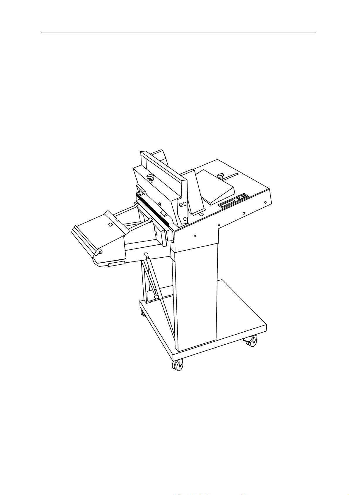
2.1 Main Components
2. Getting to know the Model 49
The Model 49 is a microprocessor controlled sheet
feeder designed to be used in a system together with
the mailer/inserter Model 45 and collator Model 306/
310.
Take a few minutes to become familiar with components of the Model 49.
1
2
3
4
5
rear
6
left
19 20 21 22
right
front
7
8
9
10
11
13 1412
18
23
15 16
17
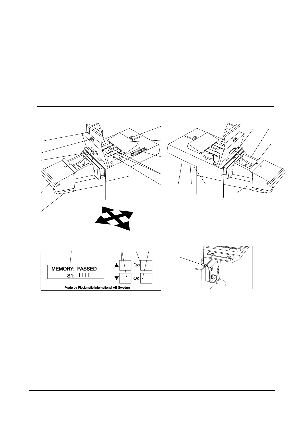
1 Insert side guides
2 Insert front guide
3 Separator pads adjustment knob
4 Outfeed sensor
5 Paper deflector
6 Docking plate
7 Insert rear guide adjustment knob
8 Insert rear guide
9 Control panel
10 Insert feed belts
11 Insert sensor
12 Connection cable jack, female
13 Termination plug jack, male
Sheet Feeder Model 49 Operator Manual
T10114 Jan 2001
The Model 49 is powered from the Power
Pack mounted on the Model 45.
14 Power cord receptacle
15 Deflector band
16 Document side guides
17 Deflector band
18 Accumulator box
19 Display
20 Arrow buttons
21 Escape button
22 OK button
23 Main power switch
2-1
Page 5
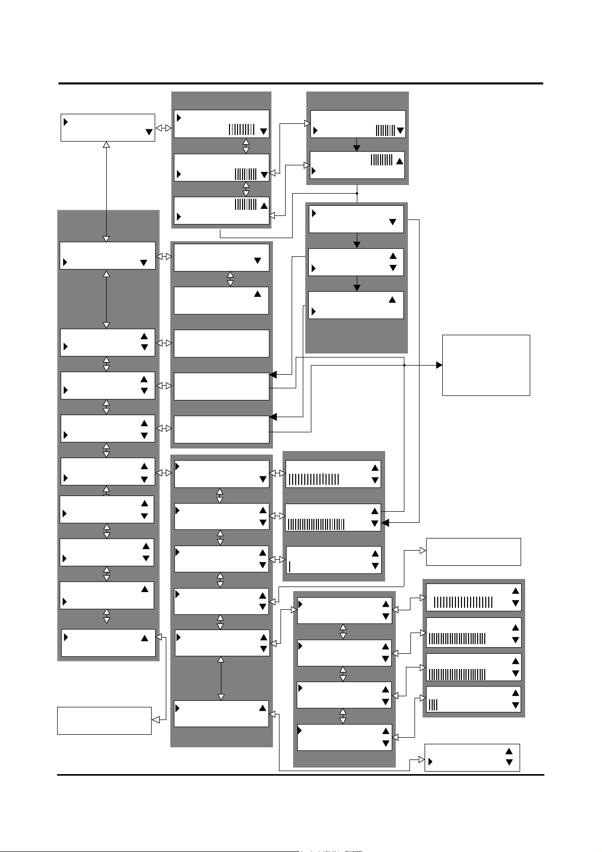
2.2 The Menus, Flow Chart
START 1
MODE On-line
Main Menu
Option
Menus
START 1
MODE On-line
MODE On-line
PROOF
PROOF
CLEAR COUNTER
Run Mode Menus
STOP 00075
PAUS
STOP 00075
PAUSE
PAUSE
ADJUST
On-Line
Off-Line
Off-Line
Stand Alone
Sheets/Set= 1
L=210mm BS=70%
Clear Counter
00075
Pause Mode Menus
STOP 00075
CONTINUE
CONTINUE
ADJUST
SETS PER HOUR
CLEAR COUNTER
SETS PER HOUR
CLEAR COUNTER
CLEAR COUNTER
PRESET COUNTER
Run Mode
Option Menus
To
Run Mode Menu
or
Pause Mode
CLEAR COUNTER
PRESET COUNTER
PRESET COUNTER
JOB SETUP
JOB SETUP
PLACEMENT (1)
PLACEMENT (1)
LANGUAGE
LANGUAGE
DIAGNOSIS
DIAGNOSIS
Run Diagnosis?
Diagnosis Menu
Counter :00100
Remaining :00025
LENGTH
SETS PER HOUR
SETS PER HOUR
SHEETS/SET
SHEET/SET
OMR
OMR
ADVANCED SETUP
ADVANCED SETUP
DEFAULT SETUP
DEFAULT SETUP
Adjustment Menus
Length: 200mm
SPH:2800
Sheets / Set 1
BELT SPEED
LUG SPEED
LUG SPEED
EJECT SPEED
EJECT SPEED
TRIG DELAY
TRIG DELAY
SETS PER HOUR
Adjustment Menus
OMR On
Off
BS: 80%
LS: 70%
ES: 100%
TD:50 ms
MODE On-line
PROOF
Sheet Feeder Model 49 Operator Manual
T10114 Jan 2001
2-2
Page 6
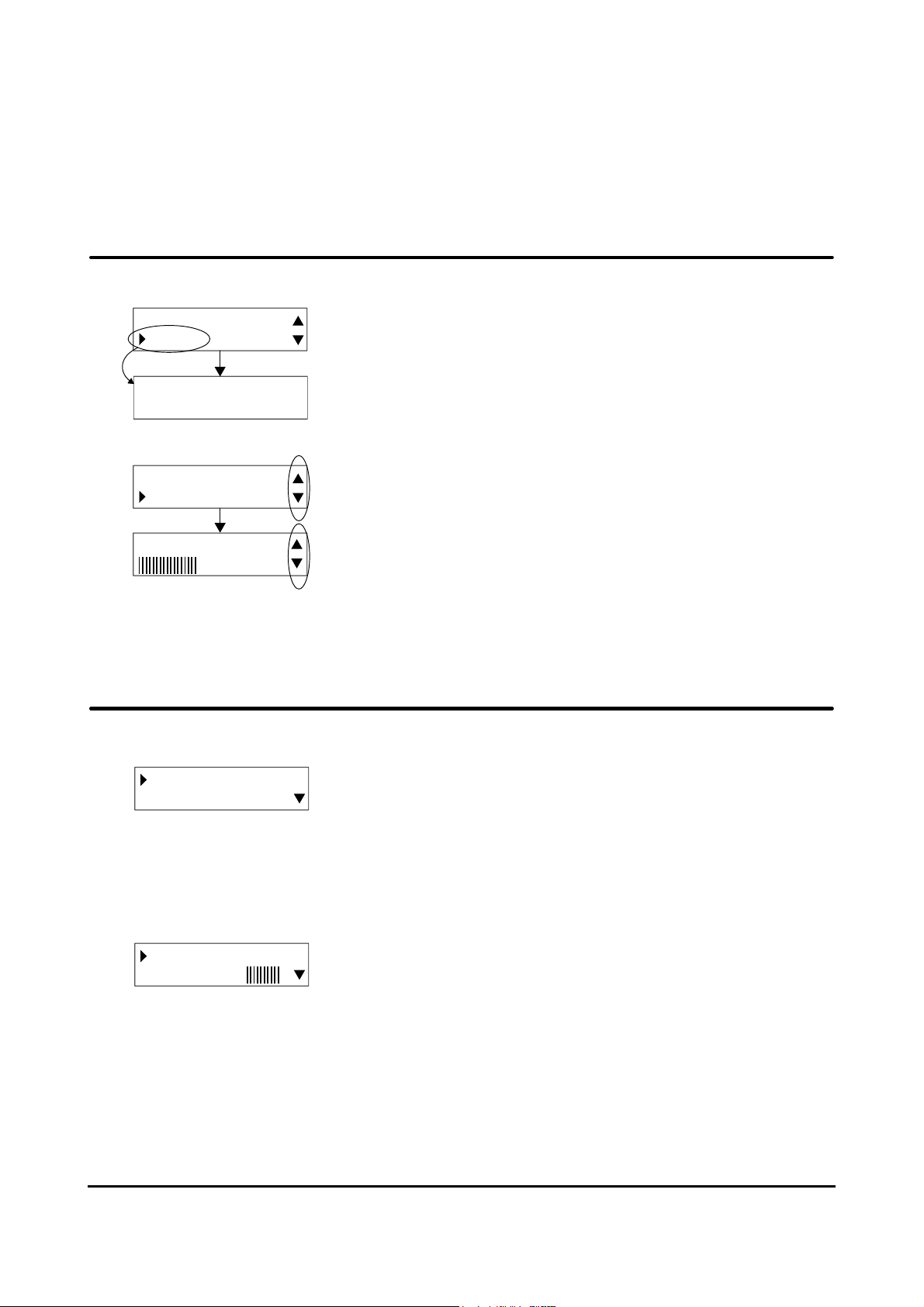
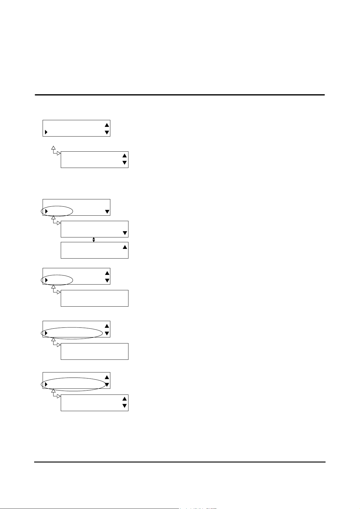
2.3 How to Read the Display
MODE On-line
PROOF
Sheets/Set= 1
L=210mm BS=70%
The arrow on the left side of the display shows option
currently selected.
Pressing the OK button on the control panel confirms your
selection and the corresponding submenu will appear in the
display.
SHEETS PER SET
LENGTH
Length: 210mm
On the right side of the display, up and / or down arrows
appear if other options can be selected.
These arrows are also displayed when the value of the
selected option can be increased / decreased, using the
arrow buttons. Use the up/down buttons on the control
panel for selecting, scrolling or adjustment.
2.4 Explanation of the Menus
START 1
MODE On-line
Main Menu
The ”Main Menu” shows ”START” when the Model 49 is
switched on. The information shows the Model 49 is ready to
start, this example on-line with the system. The number 1 in
the display indicate “Placement” of the machine.
For more information about “Placement” see table on page
7.2.
Press the OK button on the control panel to confirm your
STOP 00075
PAUSE
Run Mode Menu
selection and the Model 49 will start. When the Model 49 is
installed in a system with a Mailer/Inserter Model 45 and a
Feeder Model 306/310, the complete system can be started
from any start button on any of the units. The ”Main Menu” will
be replaced with the ”Run Mode Menu” as soon as the
Model 49/system is started.
Sheet Feeder Model 49 Operator Manual
T10114 Jan 2001
2-3
Page 7

2.4 Explanation of the Menus, cont.
The ”Run Mode Menu” is displayed when the Model 49 is
STOP 00075
PAUSE
PAUSE
ADJUST
Run Mode Menu
STOP 00075
CONTINUE
Pause Mode Menu
started. In the ”Run Mode Menu” there are three options:
”STOP”, ”PAUSE” and ”ADJUST”. Scroll / select option with
the arrow buttons and confirm with the OK button.
”STOP”: The Model 49 (and attached units) completes the
already started set and then stops. You will be returned to
the ”Main Menu”.
”PAUSE”: The model 49 (and attached units) is paused
immediately. The text ”PAUSE” will be replaced with the text
”CONTINUE”. Select ”CONTINUE” and confirm with the OK
button when you want to leave the pause mode and start the
system. Or, select ”STOP” and confirm with the OK button
when you want to leave the pause mode and stop the system.
SPH: 2800
Adjustment Menu
Clear Counter
00075
Adjustment Menu
Counter :00100
Remaining :00025
Adjustment Menu
”ADJUST”: The “Run Mode Option Menus” can be reached
both when the Model 49 is paused and while it is running. In
the “Run Mode Option” menu there are three options: “SETS
PER HOUR”, “CLEAR COUNTER” and “PRESET COUNTER”. Scroll/select option with the arrow buttons and confirm
with the OK button.
“SETS PER HOUR”: To adjust speed use the arrow buttons.
The range is 1000 to 3600 sets per hour. Default value is
1800. The speed will, however, be limited to match units
attached.
“CLEAR COUNTER”: Clears the set counter when the OK
button is pressed.
“PRESET COUNTER”: To set the preset counter use the arrow
buttons. Default value is 0. This menu can also be used to
check the setting of the preset counter and the number of sets
to go before the job is completed.
NOTE: When checking, use the “ESC” button to leave the menu
without changing the settings.
Sheet Feeder Model 49 Operator Manual
T10114 Jan 2001
2-4
Page 8
2.4 Explanation of the Menus, cont.
CLEAR COUNTER
PRESET COUNTER
Option Menu
Counter :00100
Remaining :00025
Adjustment Menu
START 00075
MODE On-line
On-Line
Off-Line
Off-Line
Stand Alone
MODE On-line
PROOF
Sheets/Set= 1
L=210mm BS=70%
Scrolling down from the ”Start Menu”, using the arrow buttons, you will find several options. Press the OK button at the
desired option to enter the corresponding ”Adjustment
Menu” as illustrated in the figure to the left. How each adjustment menu works in detail will be described later on in this
text. After adjustments press the OK button to confirm
changes or the ESC button to cancel. In either case you will
be returned to the ”Option Menu’s”.
Decide whether the Model 49 should be on-line or off-line
with the system or be operated as a stand alone unit.
This menu provides information of basic settings, number of
sheets per set, insert length and belt speed. No changes
can be made here.
PROOF
CLEAR COUNTER
Clear Counter
00075
CLEAR COUNTER
PRESET COUNTER
Clears the set counter when the OK button is pressed.
Enter the number of sets for the desired preset value using
the arrow buttons. Default value is 0. This menu can also be
used to check the setting of the preset counter and the
Counter :00100
Remaining :00025
number of sets to go before the job is completed.
NOTE: When checking, use the “ESC” button to leave the menu
without changing the settings.
Sheet Feeder Model 49 Operator Manual
T10114 Jan 2001
2-5
Page 9

2.4 Explanation of the menus, cont.
PRESET COUNTER
JOB SETUP
LENGTH
SETS PER HOUR
Length: 210mm
SETS PER HOUR
SHEETS/SET
SPH: 2800%
SHEETS/SET
OMR
BS: 100%
OMR
ADVANCED SETUP
OMR: On
Off
The menu “JOB SETUP” contains the main group of
settings.
Enter the length of the inserts (in the feed direction) using the
arrow buttons. The range is 100 to 310 mm. Default value is
200 mm.
Enter the number of sets per hour using the arrow buttons.
The range is 1000 to 3600 sets per hour. Default value is
1800. The speed will however be limited to match units
attached. When running the machine do not adjust speed
more than 1000 SPH at a time, If so, it could cause interruption per set.
Enter the number of sheets that should be fed from the
Model 49 per set using the arrow buttons. The range is 1 to
50 sheets per set. Defalut value is 1.
Enter OMR by pressing the OK button. Select OMR On or
Off.
See page (8.1) more for information .
ADVANCED SETUP
DEFAULT SETUP
The menu “Advanced Setup” contains settings of Belt
speed, Lug Speed, Eject Speed and Trig Delay.
Sheet Feeder Model 49 Operator Manual 2-6
T10114 Jan 2001
Page 10

2.4 Explanation of the Menus, cont.
BELT SPEED
LUG SPEED
BS: 100%
LUG SPEED
EJECT SPEED
LS: 70%
EJECT SPEED
TRIG DELAY
ES: 100%
TRIG DELAY
SETS PER HOUR
TD: 50 ms
Belt speed is how fast each document will be fed. Enter a
percentage using the arrow buttons. The range is 60 to
100%. Default value is 80%. If the belt speed is too slow the
documents might have problems to ”leave” the Model 49. If
the belt speed is too high, single sheets might turn over
when they are fed and booklets might bounce back.
Lug speed is how fast each set of documents will be fed
into Model 45. The range is 30 -140%. Default value is
70%.
Eject speed is a speed up function of the Lug speed. The
range is 30-140%. Default value is 100%. The value should
not be set under the “Lug Speed” value.
Trig Delay is a delay of the signal, which is sent as a start
signal to next machine in order. The range is 30-1000 ms.
Default value is 50 ms.
DEFAULT SETUP
BELT SPEED
When entering the menu “Default setup” and pressing the
OK button the “Belt Speed”, “Lug speed”, “Eject speed” and
“Trig Delay” will have their default values.
PLACEMENT (1)
LANGUAGE
Enter the “Placement” with OK button to set the place of the
machine in the line. The placement number of the machine
is depending on how many machines are in use.
See chapter 7.2 for more information.
LANGUAGE
DIAGNOSIS
Select language by pressing OK button. The languages
available in the system are Deutsch, English, Francais and
Svenska.
Default language is English.
Sheet Feeder Model 49 Operator Manual
T10114 Jan 2001
2-7
Page 11

3. Operator Instructions
3.1 Setting up the Model 49
Feeder Model 306/310
Mailer/inserter Model 45
Booklet feeder Model 46
Sheet feeder Model 49
When transporting the Model 49 the document table should
be flipped down. Flip up the document table, release the
securing plate on both sides of the document table by
holding the document table down a little bit when pushing
them away. The document table is now in its working
position.
Open the docking plate on Model 45 and position the Model
49 to the Model 45. Lock the Model 49 to the Model 45. If a
Model 306/310 is present in the system it should be positioned whith Model 49, square with the document table and
as close to the document table as possible. While calibrating the collator, adjust the paper deflector so that the leading
edge of the sheets lands between the insert feed belts on
Model 49 docking plate
the Model 45.
Sheet Feeder Model 49 Operator Manual
T10114 Jan 2001
3-1
Page 12

3.1 Setting up the Model 49, cont.
The docking plate is placed under the document table. When
the Model 49 is docked to Model 45 it is possible to push
the machine forward and backward by loosen the locking
screw.
Sheet Feeder Model 49 Operator Manual
T10114 Jan 2001
3-2
Page 13

3.1 Setting up the Model 49, cont.
paper feeder
To exclude the Model 49 from the system, just select “Offline” in the “Mode” menu.
To reactivate, select “On-line” in the “Mode” menu.
To exclude the Model 306/310 from the system, just select
“Stacking mode” on the control panel.
To reactivate, select “Third party device mode” on the
control panel.
paper deflector
Sheet Feeder Model 49 Operator Manual
T10114 Jan 2001
3-3
Page 14

3.2 Adjusting the Separation
separator pads
adjustment knob
separator pads
feed beltrollers
The drawing to the left shows schematically how the
separation works and the name of the different parts.
Tightening the separator pads adjustment knob, moves the
rollers and the separator pads closer to the feed belt. Adjust
the separation as follows.
Documents over 3 mm thickness.
Place the document between the rollers and the feed belts
as shown. Tighten the separator pads adjustment knob until
the feed belts moves when the booklet is pulled back and
forth.
Documents up to 3 mm thickness.
Place the document between the separator pads and the
feed belt as shown. Tighten the separator pads adjustment
knob so the next booklet stays in front of the separator pad
when the first one is fed.
Single sheets.
Place two sheets between the separator pads and the feed
belt as shown. Tighten the separator pads adjustment knob.
Then release until the top sheet can be pulled out.
Check adjustment in the proof menu. Press the up arrow
button to feed step by step. To feed an entire set, press the
OK button.
Sheet Feeder Model 49 Operator Manual
T10114 Jan 2001
3-4
Page 15

3.3 Loading
side guide adjustment
Slide the insert side guides away from each other. Load the
inserts. Slide the guides towards each other so that there
will be a play of 1-2 mm between the inserts and the side
guides.
The adjustment of the rear guide affects the friction between
the inserts and the feed belt. Adjustment therefore depends
on paper weight, structure and printing method as well as
what type of inserts that are fed. Proper adjustment is more
significant when running single sheets. Loosen the knob
and slide the rear guide to adjust. Tighten after adjustment.
Adjusting the rear guide too much to the left may cause
inserts not to be fed due to lack of friction. The error message ”Belt overload” will be shown in the display. Move the
rear guide to the right to increase the friction.
rear guide adjustment
front guide in rightmost position
extra weight
Adjusting the rear guide too much to the right may cause the
next insert to follow directly after the first one. The error
message ”Paper jam” will be shown in the display. Move the
rear guide to the left to decrease the friction.
Proper adjustment of the rear guide demands that the separation is properly adjusted.
The insert front guide should be positioned in its rightmost
position when booklets over 3mm are fed. For single sheets
and booklets up to 3mm position the front guide should be
positioned in its leftmost position. Lift the front guide to
adjust.
Extra weight to put upon the documents, to get a proper
separation.
front guide in leftmost position
Sheet Feeder Model 49 Operator Manual
T10114 Jan 2001
3-5
Page 16

3.3 Loading, cont.
scale
Slide the document side guides away from each other. Read
the scale on the bottom of the document board, and set the
same width as the loaded inserts.
When feeding longedge the short paper deflector should be
placed on the edge of the cover, and the long paper
deflector should hang down on the document table. When
feeding short edge, the short paper deflector should be
placed in the hole at the top of the cover, and the long paper
deflector should also be placed in the same hole.
Sheet Feeder Model 49 Operator Manual
T10114 Jan 2001
3-6
Page 17

3.4 Programming the Model 49
Switch on the power. Select ”Mode” and press the OK button. Choose ”On-line” if the Model
49 is used together with a feeder Model 306/310 and/or a mailer/inserter Model 45 and/or
Booklet Feeder Model 46. Choose ”Stand Alone” to use the Model 49 as a stand alone
document feeder. If the Model 49 should be inactivated choose ”Off-line”. Confirm your
choice by pressing the OK button.
Select “Job Set” and press the OK button. From “Adjustment Menu” it is possible to scroll and
enter any of the adjustable parameters.
Select ”Length” and press the OK button. Enter the length of the inserts (in the feed direction)
using the arrow buttons. The range is 100 to 310 mm. Default value is 200 mm. Confirm by
pressing the OK button.
Select ”Sets per hour” and press the OK button. Enter the number of sets per hour using the
arrow buttons. The range is 1000 to 3600 sets per hour. Default value is 1800. The speed will
however be limited to match units attached. Confirm by pressing the OK button.
Select ”Sheets per set” and press the OK button. Enter number of sheets per set using the
arrow buttons. The range is 1 to 50 sheets per set. Default value is 1. Confirm by pressing the
OK button.
Select “Advanced Setup” and press the OK button.
Select ”Belt speed” and press the OK button. Enter a percentage using the arrow buttons.
The range is 60 to 100%. Default value is 80%. Confirm by pressing the OK button.
Select “Lug Speed” and press the OK button. Enter a percentage using the arrow buttons.
The range is 30 to 140%. Default value is 70%. Confirm by pressing the OK button.
Select “Eject Speed” and press the Ok button. Enter a percentage using the arrow buttons.
The range is 30 to 140%. Default value is 100%. Confirm by pressing the OK button.
Select “Trig Delay” and press the OK button. Enter the time (millisecond) using the arrow
buttons. The range is 30 to 1000 ms. Default value is 50 ms. Confirm by pressing the OK
button.
Sheet Feeder Model 49 Operator Manual 3-7
T10114 Jan 2001
Page 18

3.4 Programming the Model 49, cont.
If you wish to reset the set counter select ”Clear counter” and press the OK button. The next
menu shows the actual value of the set counter. Clear the set counter by pressing the OK
button.
If you wish to program a specific number sets for a job, select ”Preset counter” and press
the OK button. The next menu shows the actual value of the preset counter and how many
more sets to go to finish the job. Enter a new value using the arrow buttons.
Default value is 0. Confirm by pressing the OK button.
3.5 Start inserting
After the setting up of attached units according to their respective operator instructions, the
system is ready to be started. The system can be started and stopped using the start and
stop buttons on any unit in the system.
Sheet Feeder Model 49 Operator Manual 3-8
T10114 Jan 2001
Page 19

4.1 Diagnosis
4. Diagnosis
Note: Before starting the diagnosis, all inserts must be removed.
LANGUAGE
DIAGNOSIS
Run Diagnosis?
MEMORY:PASSED
S1:
Exemple: Display shows that
the Model 49 passed the
memory test and testing of
sensor S1 in progress.
Select ”DIAGNOSIS” from the ”Options Menu” and press the
OK button at the ”Diagnosis Menu” to start the self test.
The self test will check: memory, insert sensor (S1), outfeed
sensor (S2), set sensor (S3), lug belt senor (S4),voltage
supplied from the power pack and feed belt motor (M1),set
delivery motor (M2) and (OMR) if it is connected to the
system. During the test, the display will show which part that
currently is tested. After the test you can scroll with the arrow
buttons to check that all parts diagnosed, passed the test.
If any tested part did not pass the test.
If any of the sensors should fail the self test, check if sensors
are blocked with paper dust. If so, clean them and perform
the self test again. If cleaning does not correct the problem,
or if any other of the parts checked fails the test, have the
Model 46 checked by a qualified technician.
5. Maintenance
5.1 Cleaning the Feed Belts
Clean the insert feed belts using a mild soap detergent every
10 000 feeds or earlier if needed.
Sheet Feeder Model 49 Operator Manual
T10114 Jan 2001
4-1
Page 20

6.1 Problem Solving
6. Problem solving
egassemdeyalpsiDsesuacelbissoP
WARNING
Comm. Error
ERROR Purge
Paper Jam
noitca/noitanalpxE
-ffonidetrats94ledoM.1
nehwedomenil-noroenil
.ffoderewopsi54ledoM
elbacnoitacinummoC.2
dna54ledoMneewteb
rodetcennocton94ledoM
.evitcefed
xobnoitacinummoC.3
.evitcefed
si013/603ledoMehT.4
-mmoCehtroffodehctiws
.detcennoctonsixob
htgneltresnitcerrocnI.1
.deretne
foesuacebdeefelbuoD.2
detsujdayltcerrocni
.noitarapes
rosnesdeeftuO.3
.detanimatnocroevitcefed
.xob-mmoc
.elbattnemucod54
.naicinhcet
.no54ledoMehthctiwS.1
.unemtratsehtretne
ehtnistinuehtneewtebnoitacinummoC
.dehsilbatseebtondluocmetsys
.elbacnoitacinummocecalper/kcehC.2
metsys/xobnoitacinummocehtevaH.3
.naicinhcetdeifilauqaybdekcehc
ehttesdna013/603ledoMehtnonruT.4
ehttcennoC.enil-FFOroenil.NOenihcam
ledoMehtotylreporpdefdetropertons/tresnI
ni,htgneltresnitcerrocehtretnE.1
.4.2noitcesotgnidrocca,sretemillim
.4.2noitcesotgnidroccanoitarapestsujdA.2
.tsudhtiwdetanimatnocebyamrosneS.3
nuR.rosnesdeeftuoehtnaelc/kcehC
ehtfI.rosnesfosutatsyfirevot"sisongaiD"
,evitcefedsirosnesehttahtseifirevtsetfles
deifilauqaybdekcehc94ledoMehtevah
ehtegrupotnottubworrapuehtsserP
retneotecnonottubcsEehtsserP.s/tresni
tahthtgneltresnitahwkcehC.unemfoorpeht
oteromecnonottubcsEehtsserP.deretnesi
ERROR Purge
Belt over load
.noitarapes
.evitcefed
Sheet Feeder Model 49 Operator Manual
T10114 Jan 2001
esuacebdefstresnioN.1
detsujdayltcerrocnifo
rosnesdeeftuO.2
.evitcefedrotomdeeF.3
.rosnesdeeftuo
sirosnesehttahtseifirevtsetfleseht
.naicinhcetdeifilauq
.naicinhcetdeifilauq
ehtegrupotnottubworrapuehtsserP
.unemtratsehtretneoterom
ehtsehcaerstresniynatahtderetsigertonsitI
.4.2noitcesotgnidroccanoitarapestsujdA.1
fI.rosnesfosutatsyfirevot"sisongaiD"nuR.2
aybdekcehc94ledoMehtevah,evitcefed
deeffosutatsyfirevot"sisongaiD"nuR.3
sirotomehttahtseifirevtsetflesehtfI.rotom
aybdekcehc94ledoMehtevah,evitcefed
retneotecnonottubcsEehtsserP.s/tresni
ecnonottubcsEehtsserP.unemfoorpeht
6-1
Page 21

6.1 Problem Solving
egassemdeyalpsiDsesuacelbissoPnoitca/noitanalpxE
6. Problem Solving
WARNING Purge
Feeder is empty
System ERROR
Interlock at (X)
System ERROR
Jam at (X)
.stresnioN.1
revoctonseodstresnI.2
tresniehtnorosneseht
.elbat
evitcefedrosnestresnI.3
tinutahctiwskcolretnI.1
si"X"rebmunDIhtiw
.detautca
.yrtiucricninoitpurretnI.2
DIhtiwtinutamaJ.1
.detautcasi"X"rebmun
.yrtiucricninoitcnuflaM.2
.elbattresnieht
.daoleR.1
.3.3noitcesotgnidrocca
sirosnesehttahtseifirevtsetfleseht
.naicinhcetdeifilauq
.melborpehtgnisuac
.naicinhcet
.ylreporpdetcennoc
sitahttinuhcihwyfitnediot4.2noitces
.melborpehtgnisuac
.ylreporpdetcennoc
nostresniynaeraerehttahtderetsigertonsitI
ylreporpdedaolerastresniehttahtkcehC.2
fI.rosnesfosutatsyfirevot"sisongaiD"nuR.3
aybdekcehc94ledoMehtevah,evitcefed
sitahttinuhcihwyfitnediot4.2noitceseeS
eratonsehctiwskcolretniehttahtkcehC.1
,detcerrocebnactonmelborpfI.detautca
deifilauqaybdekcehctinu/metsysehtevah
eraselbacnoitacinummocehttahtkcehC.2
ehtevah,detcerrocebnactonmelborpfI
.naicinhcetdeifilauqaybdekcehctinu/metsys
ees,yrassecenfI."X"tinutamajraelC.1
eraselbacnoitacinummocehttahtkcehC.2
ehtevah,detcerrocebnactonmelborpfI
.naicinhcetdeifilauqaybdekcehctinu/metsys
Sheet Feeder Model 49 Operator Manual
T10114 Jan 2001
6-2
Page 22

7.1 Specifications
ezisrepaP.niMmm002x*001
thgiewrepaP.niMmsg06
:sdeepS
7. Specifications
NOITACIFICEPS94LEDOM
.xaMmm503x*523
.xaM
:noitatsrotalumuccaotnI
tes/steehs2,*FES,4A
tes/steehs3,*FEL,4A
tes/steehs4,*FEL,5A
:noitatsrotalumuccamorF
ruoh/steehs0027otpU
ruoh/steehs00821otpU
ruoh/steehs00441otpU
ruoh/stes0063otpU
ssenkcihttnemucodxaMmm8
thgiehkcatS.xaMmm071
noitceteddeefssiMseY
noitcetedmaJseY
thgieHmm0211
htdiWmm065
htpeDmm084
thgieWgk25
egatloV 54ledoMnokcaPrewoPmorfdeilppuS
* 100 mm in the fedding direction
* 325 mm in the feeding direction
* Rear Guide not effective below 140 mm
* SEF = Short edge feed
* LEF = Long edge feed
Sheet Feeder Model 49 Operator Manual
T10114 Jan 2001
7-1
Page 23

7.2 Specifications for Placement
The settings of placement gives the operator an opportunity to select the working position
of the machines. The table below show the available state of placement for each machine.
The machine with number 1 feeds first then number 2 and so on. The Model 45 is always
the last machine in the line. Placement can be selected from each machine, follow the
operator instruction for each machine.
54ledoM64ledoM94ledoM013/603ledoM
4321
4213
4132
321 esuniton
312 esuniton
3esuniton21
3esuniton12
31 esuniton2
32 esuniton1
21 esunitonesuniton
2esuniton1esuniton
2esunitonesuniton1
Sheet Feeder Model 49 Operator Manual
T10114 Jan 2001
7-2
Page 24

8. OMR
8.1 OMR mark Layout
The thickness of the marks should be between 0,5 to 0,8 mm (1½ – 2 pt). The length of the
marks should be 5 mm or more. The distance between the marks should be 3 mm. The length
of the total number of marks should be 15 mm ± 0,4 mm.
8.2 OMR Positioning
The OMR marks must not be printed within 10 mm from leading edge or 40 mm from trailing edge
of the sheet. Beside these limitations the OMR marks can be placed anywhere on the sheet. The
area covered by the OMR reader, between the leading edge and the OMR marks must be free from
text, images, and holes or similar in order not to confuse the reading procedure. Exception: A single
line before the OMR field, at least 10 mm away from the gate marks, will be ignored. Any print after
the OMR field will also be ignored. It is suggested that the margins on either side should be used for
placing the OMR marks. It is also advisable to place the OMR code closer to the leading edge
rather than the trailing edge, because of line-up reasons.
Area covered by OMR reader
Sheet Feeder Model 49 Operator Manual 8-1
T10114 Jan 2001
Page 25

8.3 How to Use the OMR Marks
Mark Structure
Gate 1
Gate 2
E. O. S.
Parity
Seq. 1
Seq. 2
Gate 1, Gate 2
The Gate 1 and Gate 2 act as start - reading - marks. Each mark
sequense must always include the two Gate marks. If not, the sheet
will be detected as blank.
Sequence 1 - 2
The “Seq1” & “Seq2” marks are needed for the OMR reader to detect
that the sheets in a set are fed in the right order. The sequence is: No
marks, S1 mark, S2 mark, S1 and S2 mark, no mark and so on. Each
new group shall start with the sequence number 0 (no marks), see
examples below.
End Of Set (E.O.S)
To indicate the last sheet in a set, an ”End Of Set” mark is required.
Parity
There must allways be an even number of marks on each sheet. When
needed, add the parity mark.
The example below illustrates a set containing eight sheet.
Page
1 2 3 4 5 6 7 8
G1
G2
EOS
P
S1
S2
The example below illustrates a set containing five sheets.
Page
1 2 3 4 5
Sheet Feeder Model 49 Operator Manual 8-2
T10114 Jan 2001
Page 26

Notes
 Loading...