

Page 1
Stapler Folder Model 102
Operator Manual
February 1999
Part No. 87499
Page 2

1. Introduction
Table of contents
1.1 Operational safety
2. Getting to know the Model 102
2.1 Main components
2.2 Control panel
3. Operator instructions
3.1 Switching on the Model 102
3.2 Setting up the Model 102
3.3 Feeding and adjusting a test set
3.4 Making fine adjustments
3.5 Beginning the production
3.6 Restoring the factory set A3, A4 or A5 program
3.7 Jam indications
4. Maintenance
4.1 Removal/replacement of the staple cartridge
4.2 Removal/replacement of the stapler head
4.3 Cleaning fold rolls
4.3 Lubrication of parts
1-1
2-1
2-4
3-1
3-2
3-5
3-7
3-8
3-9
3-10
4-1
4-4
4-6
4-7
5. Specifications
5.1 Specifications
Stapler Folder Model 102 Operator Manual
T10087 February 1999
5-1
i
Page 3

1. Introduction
1.1 Operational safety
Attention to the following notes ensures the continued safe operation of your equipment.
Always connect the equipment to a properly grounded power source receptacle. In
doubt, have the receptacle checked by a
qualified electrician.
WARNING: Improper connection of the
equipment grounding conductor can result
in electrical shock.
Always follow all warnings marked on, or
supplied with, the equipment.
Always locate the equipment on a solid
support surface with adequate strength for
the weight of the machine.
Always exercise care in moving or relocating the equipment.
Always keep magnets and all devices with
strong magnetic field away from the machine.
Never use a ground adapter plug to connect the equipment to a power source
receptacle that lacks a ground connection
terminal.
Never attempt any maintenance function
that is not specifically described in this
documentation.
Never remove the covers or guards that are
fastened with screws.
Never install the unit near a radiator or any
other heat source.
Never override or “cheat” electrical or
mechanical interlock devices.
Never operate the equipment if you notice
unusual noises or odours. Disconnect the
power cord from the power source receptacle and call your customer service engineer
to correct the problem.
Stapler Folder Model 102 Operator Manual
T10087 Febrary 1999
1-1
Page 4
2. Getting to know the Model 102
2.1 Main components
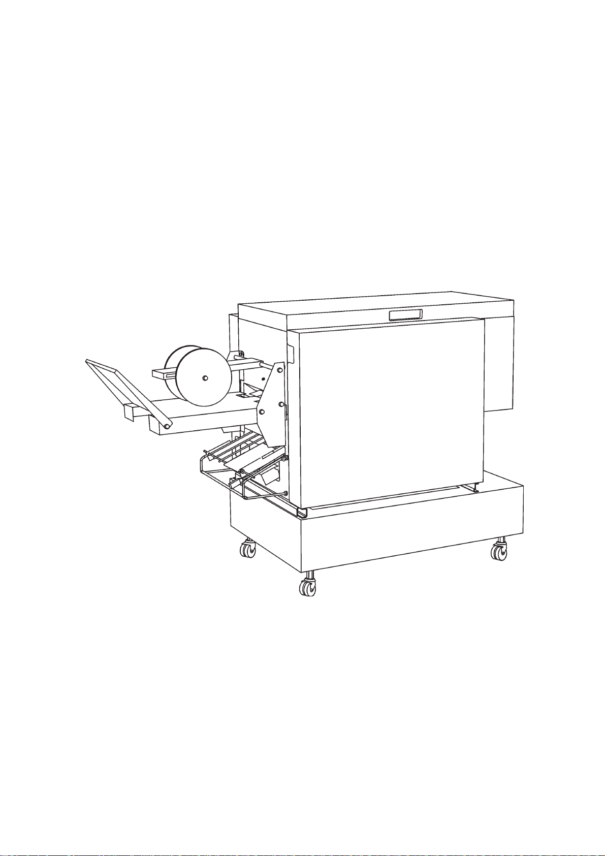
The Model 102 can be quickly and easily connected to the Air Feed Collator Model 100 for
on-line booklet making. The Model 102 also makes an ideal manual hand feed booklet
maker with an optional manual feed tray .
The Model 102 is equipped with motor driven stapler heads (5000 staples per head), the
anvils are of the clinch type, ensuring professional flat staples. In addition, the operation
that fold the paper provide a sharp booklet fold.
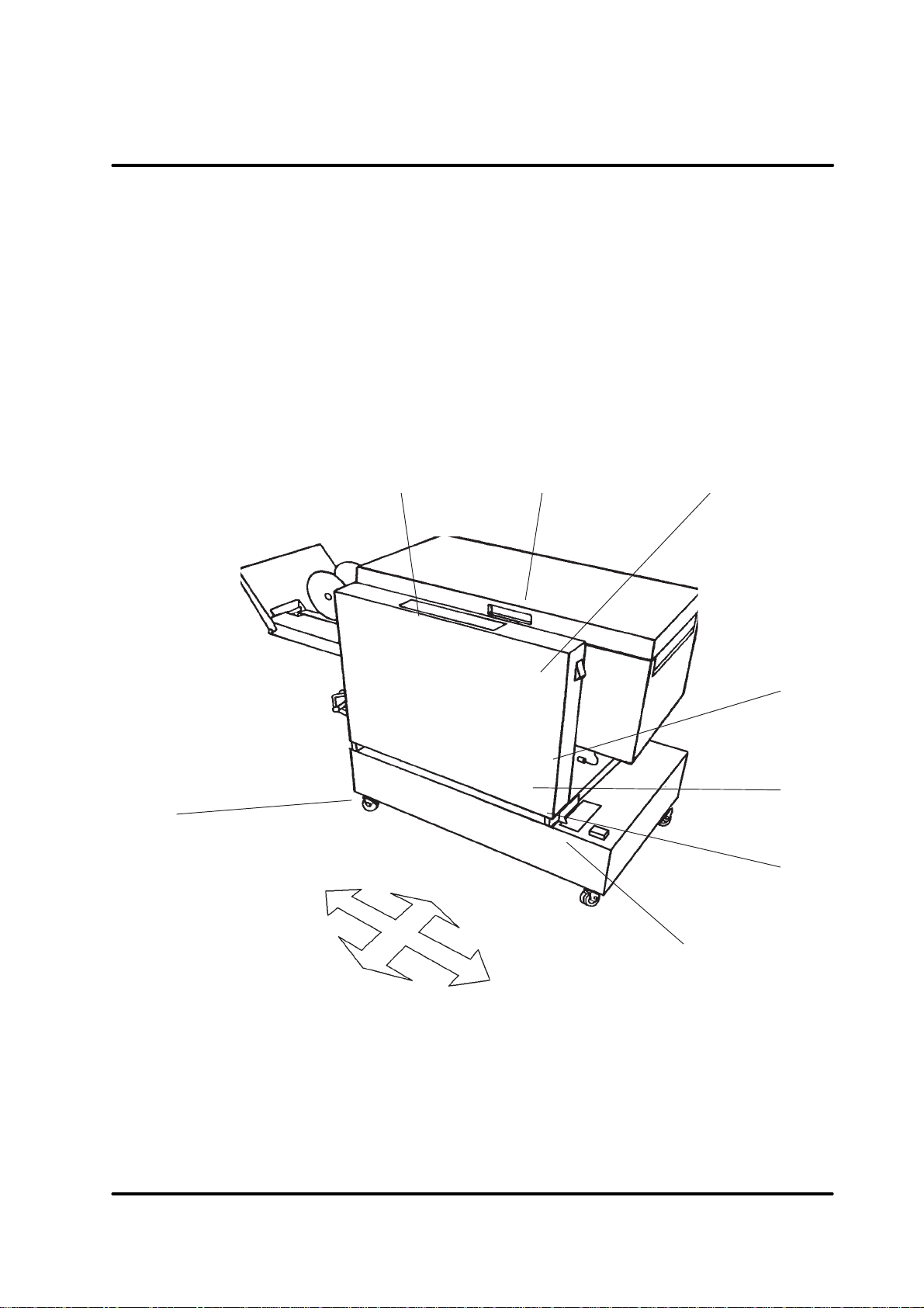
T ake a few minutes to get familiar with the main components of the Model 102.
23 4
1
left side
1 Castor lock
2 Control panel
3 T op cover
4 Power switch
front side
5
6
7
rear side
8
right side
5 Ground fault interrupter
6 Power receptacle/main fuse
7 Machine positioning scale
8 Foot pedal
Stapler Folder Model 102 Operator Manual
T10087 February 1999
2-1
Page 5
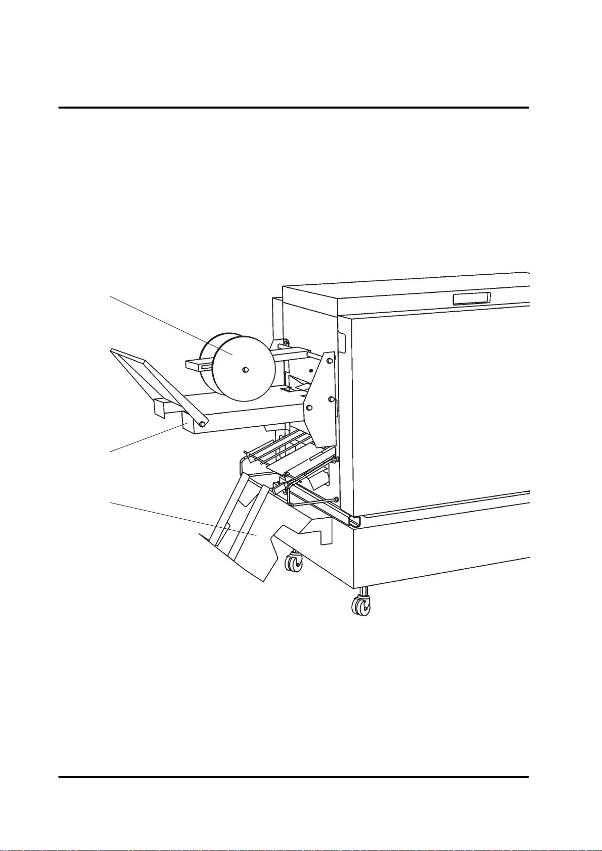
2.1 Main components, continues
The belt stacker is used when stapling/folding or folding only is selected. The function of the
belt stacker is the same whether the feed is automatic or manual.
The back of the belt stacker is normally angled upward (about 15 degrees to horizontal),
but can be lowered to allow booklets to drop into a box.
The output wheels should be positioned at the innermost notch for A4, A5 ( 8.5”x14”,
8.5”x1 1”) and similar sizes, at the middle notch for A3 (1 1”x17”) and similar sizes, and at
the outermost notch for storage. Using customized formats the output wheels should be
positioned approximately 50mm from the leading edge of the first set.
1
2
3
1 Set output wheel
2 Belt stacker
3 Delivery tray (optional)
The optional delivery tray is used for side or corner stapling if there is no trimmer attached.
When side or corner stapling is selected, the fold stop moves away automatically and the
stapled sets are delivered onto the tray .
Stapler Folder Model 102 Operator Manual 2-2
T10087 Febrary 1999
Page 6
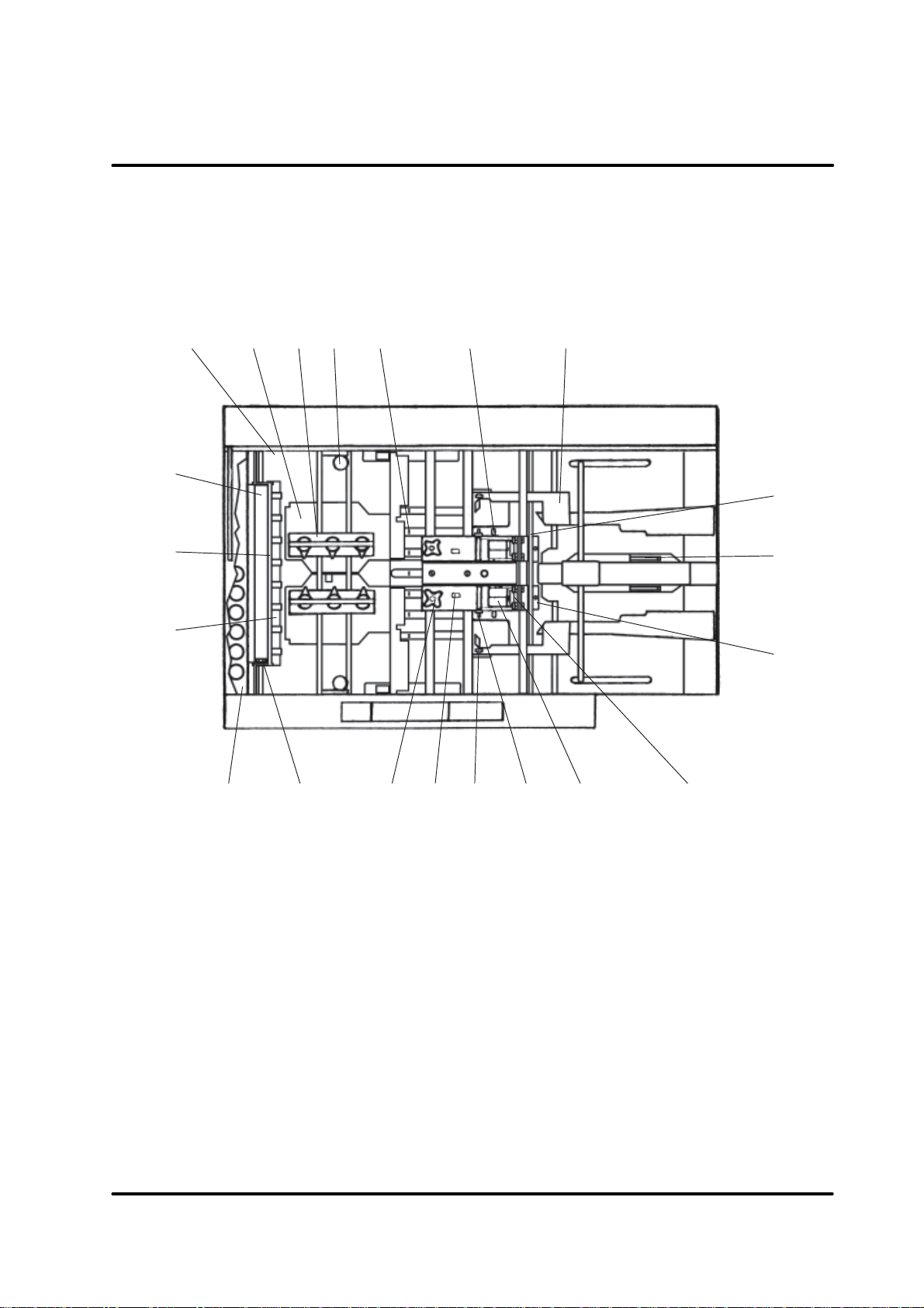
2.1 Main components, continues
The Model 102 interior has parts that you will come in contact with when making the fine
adjustments to the booklet or when performing maintenance.
12 5 7
4
3
6
11
12
13
8
9
10
14 15 16 17 18 19 20
1 T otal set counter
2 Paper guide
3 Ball cage
4 Fold adjust lever
5 Staple stop
6 Lock pin
7 Side jogger
8 Anvil position scale
9 Back jogger
10 Anvil
11 Upper fold roll
12 Fold roller guide cassette
Stapler Folder Model 102 Operator Manual
T10087 February 1999
21
13 Lower fold roll
14 T ool box including balls, allen key
and open end wrench
15 Hex grip, upper fold roll
16 Thumb screw for stapler assembly
17 Staple detection switch
18 Side jogger incorrectly positioned
actuator
19 Side jogger incorrectly positioned
switch
20 Staple cartridge
21 Stapler head
2-3
Page 7
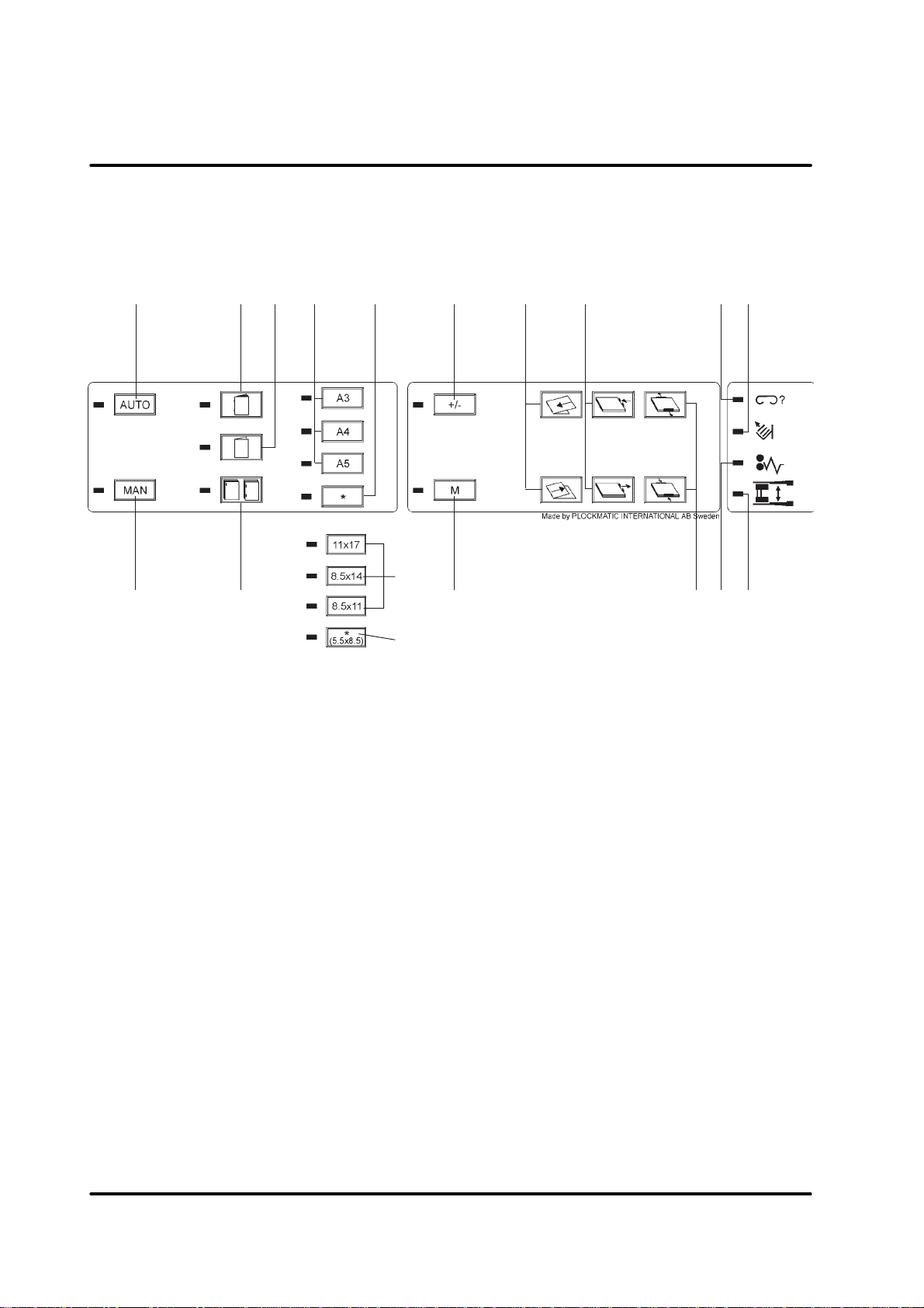
2.2 Control panel
1
43
7a6
8
11
1413
6
2
5
9
12
151016
7b
U.S. paper sizes
1 Automatic set feed mode
2 Manual set feed mode
3 Stapling and folding
4 Folding only
5 Side stapling or corner stapling
6 Factory preprogrammed paper size
(Can also be used to store customer
programmable paper size)
7a Customer programmable paper size
7b Factory preprogrammed paper size/
Customer programmable paper size
8 Programming access/format ad-
justment access
9 Memory
10 Fold position adjustment
11 Back jogger position adjustment
12 Side jogger position adjustment
13 Staple(s) missing indicator
14 Stacker full Indicator
15 Paper jam indicator
16 Staplers or side jogger incorrectly
positioned indicator
Stapler Folder Model 102 Operator Manual 2-4
T10087 Febrary 1999
Page 8
3. Operator instructions
3.1 Switching on the Model 102
This chapter explains the operations for making the booklets, whether the Model 102 is in
automatic or manual mode.
The following steps apply to both automatic and manual
feed.
1 Plug the Model 102 into the wall outlet.
2 Set ON/OFF switch to ON position.
2
3 Wait until there is steady illumination of the paper size
indicator. If you previously used the Model 102, the
paper size that was last used will illuminate.
Stapler Folder Model 102 Operator Manual
T10087 February 1999
3-1
Page 9

3.2 Setting up the Model 102
This section explains how to set up the Model 102 and do a test run. After the test run you
can do fine adjustments of the settings, if necessary . When you are satisfied with the test
run you can begin production.
Select a paper feed mode
1 If the papers are fed from a collator , press the AUT O button.
NOTE: Make sure the Model 102 is correctly positioned on the base. Press
the green foot pedal on the base and move the Model 102 to the
corresponding format according to the machine positioning scale.
2 Or, if the p apers are fed manually , press the MANUAL button.
Select the type of finishing
Y ou can select staple and fold, fold only , corner st apling or side stapling for
your booklets.
NOTE: For corner stapling and side stapling an optional delivery tray is
necessary if a trimmer is not installed. If a trimmer is present,
consult the trimmer operator manual.
Pressing any of the following buttons will start the paper size program
indicators to light up in sequence (running light), waiting for you to select
the correct paper size program.
3 Press this button for stapled and folded booklets.
4 Press this button for non stapled, folded booklets.
5 Press this button for corner stapling or side stapling. Disable either
stapler by removing it according to section 4.2, and switch off the
staple detection switch if corner stapling is chosen.
NOTE: Side stapling or corner stapling of A3 paper format is not possi-
ble.
6. Depending of the actual paper size and/or the selected booklet form
you might want to change the position of the staples.
Use the allen key to loosen the anvil(s). Move the anvil(s) to the desired position and tighten the screw(s). Loosen the thumb screw(s) for
the stapler assembly . Centre the stapler assembly over the anvils and
thighten the thumb screw(s).
Stapler Folder Model 102 Operator Manual
T10087 Febrary 1999
3-2
Page 10

3.2 Setting up the Model 102, continues
min 8 mm
min 8 mm
NOTE1:If the distance between the stapler and the side jogger is to
narrow, the staplers or side joggers incorrectly positioned indicator will be illuminated (also see section 3.7.). Make sure the
distance between the actuator and the switch is no less than 8
mm.
NOTE2:Depending of the previous job setup you might have to select
paper size program before you move the staplers apart.
The anvil position scale indicates the distance, in millimetres, from centre
to centre (cc) of the staples.
T ype of finishing Paper format Setting (cc)
booklet making 5,5”, CD 98
booklet making A5 105
booklet making 8,5”, A4 120
booklet making 11”, A3 120 or 200
side stapling 1 1”, A4 144 (Recommended)
corner stapling 11” 255 (Recommended)
corner stapling A4 273 (Recommended)
NOTE: Using other settings could result in poor staple/fold result.
lead
edge
trail
edge
U.S. paper
sizes
Select a paper size program
For your convenience, the A3, A4 and A5 (8.5"x1 1", 8.5x14", 11"x17" and
5.5”x8.5”) paper size programs were factory set with appropriate jogging,
staple position and fold line position. The jogging, staple position and the
fold line position may need fine adjustments depending on the type of
paper used.
NOTE: If you want to use a custom format, select the next bigger (dis-
tance between the lead edge and the trail edge) paper size program. Fine adjustments will be explained in section 3.3 and 3.4.
7 Press the appropriate button to select paper size program.
The A3 button for 297 x 420 mm. - Position the output wheel at the
middle notch.
The A4 button for 297 x 210 mm. - Position the output wheel at the
or
The A5 button for 148 x 210 mm. - Position the output wheel at the
The * button for customised size. - Position the set output wheel
innermost notch.
innermost notch.
appro. 50 mm from the leading
edge of the first set.
Stapler Folder Model 102 Operator Manual
T10087 February 1999
3-3
Page 11

3.2 Setting up the Model 102, continues
8. When selecting staple and fold, or fold only the configuration of the
balls in the ball cage is important. The purpose is to apply enough
pressure on the set to ensure proper alignement against the fold stop
before the set is being folded. By doing that the set will be correctly
folded at the middle of the set. The Model 102 is delivered with glass
balls at the left side and plastic balls at the right side of the ball cage
which should cover most jobs.
Depending on the number of sheets in each set and the stiffness of the
papers used you might need to change the configuration. In the tool
box you can find 2 steel balls, 2 glass balls and 2 plastic balls.
The heaviest configuration, for several sheets with high stiffness, is 2
steel balls at the left side and 2 glass balls at the right side. The lightest configuration, when running just a few sheets with low stiffness, is
plastic balls at the left only .
If your booklets comes out with the staples on the back of the booklet
the configuration is to heavy . T o many and/or to heavy balls allowed the
set to buckle (travel too far) before it was folded.
123
If your booklets comes out with the staples on the front, and/or with a
skew fold, the configuration is to light. By using not enough and/or to
light balls the set did not travel all the way down to the fold stop and
was not aligned correctly .
senilediugnoitarugifnocllaB
htiwgnidlofylnosteehsegralelgniS
ssenffits/thgiewrepapwol
wolhtiwstesteehswefdedlof-delpatS
ssenffits/thgiewrepap
noitarugifnocdradnatSssalG- citsalP
steehsdedlof-delpatslareveSssalG- ssalG
steehsdedlof-delpatsdrahlareveSleetS- ssalG
123
citsalP--
citsalP-citsalP
123
steehs
Stapler Folder Model 102 Operator Manual
T10087 Febrary 1999
dlofretnecehtnosruccosgnikramfI
dedlof-elpatslarevesgninnurnehw
ssalGcitsalPcitsalP
3-4
Page 12

3.3 Feeding and adjusting a test set
The first time you use the Model 102, or when you change to a different paper size program, you run one test set and make necessary adjustments before you begin production.
Y ou can use automatic feed from the collator , using the calibration option or manual feed.
Coarse adjustment
Y ou have already selected either automatic or manual operation, type of
finishing, and paper size program.
1 Press the program access button.
2 Open the cover.
3 Look at the side jogger scale.
back jogger arm
side jogger scalestaple/fold line scale
4 Press and hold the side jogger button until the side jogger reaches the
position on the side jogger scale for the test set.
5 Look at the staple/fold line scale.
6 Press and hold the back jogger button until the back jogger reaches
the position on the staple/ fold line scale for the test set.
(Manually lift the back jogger arms)
NOTE: The staple/fold line scale does not show the correct position for
the set when corner stapling or side stapling is chosen.
Stapler Folder Model 102 Operator Manual 3-5
T10087 February 1999
Page 13

3.3 Feeding and adjusting a test set, continues
7 Close the top cover.
8 Feed one set of the chosen paper size into the model 102 (The ma-
chine will repeatedly make a jog cycle).
9 Open the top cover.
moving the
staple stop
towards the
infeed
moving the
staple stop
towards the
outfeed
10 Press and hold the staple stop adjustment button until the trail edge of
the set reaches the paper size mark on the staple fold/line scale. If the
required paper size mark not is visible (the set is to close to the
infeed), press the staple stop adjustment button until the set passes
the required paper size mark (towards the outfeed). Ensure that the
set is aligned against the staple stop and press the staple stop adjustment button until the trail edge of the set reaches the paper size mark
on the staple fold/line scale.
11 Press the side jogger button until the side joggers jogg the set firmly
without making a buckle in the set.
12 Press and hold the back jogger button until the back jogger is approxi-
mately 1 mm from the set.
13 T o store your settings:
• press the format adjustment access button (the +/- button) to keep your
settings temporarily . Y our settings are not stored but will remain until a
paper size format button is pressed even if the power is switched off.
• press the memory button to store your settings on the actual paper
size button, earlier selected according to section 3.2.
• or, select any other paper size program button and then press the
memory button.
NOTE1:Side stapling or corner stapling of A3 paper format (or similar
sizes) is not possible.
NOTE2:You can store 4+4 different settings. Four in the staple/fold or
fold only finishing mode, and four in the corner or side stapling
finishing mode.
14 Close the top cover. The paper set moves to the belt stacker .
15 In booklet finishing mode: If the cover is torn from the body sheets
increase the gap between the fold rolls by adjusting the fold adjust
levers from the factory setting 1 to a higher number.
Stapler Folder Model 102 Operator Manual 3-6
T10087 Febrary 1999
Page 14

3.4 Making fine adjustments
This section shows you how to make fine adjustments of the booklet.
The test run has just been completed and the Model 102 is switched ON.
Y our selection for paper size program is still in effect.
1 Press the program access button.
2 Feed one set.
3 Open the top cover.
MELBORPNOITCERROCNOTTUB
ehtfosegdeedisehT
nevetonerasteehs
ehtfosegdeedisehT
demrofederasteehs
fosegdemottob/potehT
nevetonerasteehs
ehtfokcabrorevocehT
degamaderastelkoob
,deretnectonsidlofehT
sitelkoobehtfopoteht
trohsoot
,deretnectonsidlofehT
sitelkoobehtfopoteht
gnoloot
NOTE: Pressing the adjustment buttons shortly will increase/decrease
the position with approximately 0.5 mm.
resolc
trapa
sreggojedisehtevoM
sreggojedisehtevoM
reggojkcabehtevoM
tesehtotresolc
reggojkcabehtevoM
tesehtmorfyawa
.rehgihpotsdlofehtteS
tsumreggojkcabehT
uoyretfadetsujdaereb
noitisopdlofehttsujda
.rewolpotsdlofehtteS
tsumreggojkcabehT
uoyretfadetsujdaereb
noitisopdlofehttsujda
4 Store your settings according to section 3.3, item 13.
5 Close the top cover. The booklet transport s to the set output tray .
6 Check the booklet. If it is still not good, repeat the fine adjustment.
Otherwise go to section 3.5 Beginning the production.
Stapler Folder Model 102 Operator Manual
T10087 February 1999
3-7
Page 15

3.5 Beginning the production
This section shows you how to begin production. Y ou have run a test set
and made necessary adjustments.
The Model 102 is switched ON.
Automatic operation
1 Verify that the indicator light s, associated with the paper size button
(example showing A3 selected) and type of finishing (example showing stapling and folding) that you selected, is on.
2 Check that the Model is correctly positioned on the base according to
the machine positioning scale.
3 Start your collator . The set s are automatically fed into the Model 102
and the booklets appear on the belt stacker .
NOTE: After a successful booklet production, if you change the paper
size or weight, you may need to go back to section 3.3 Feeding
and adjusting a test set.
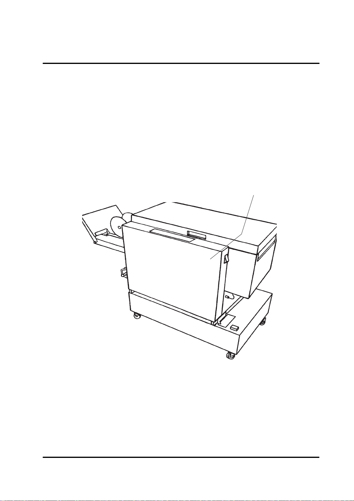
Manual operation
1 Verify that the indicator light s, associated with the paper size button
(example showing A4 selected) and type of finishing (example showing side/corner stapling) that you selected, is on.
2 Check that the optional delivery tray for side/corner stapling is in-
stalled. Or , if a trimmer is present, consult the trimmer operator
manual.
T o facilitate hand feeding, use an optional feeding tray as shown in the
drawing below .
Stapler Folder Model 102 Operator Manual 3-8
T10087 Febrary 1999
Page 16

3.6 Restoring the factory set A3, A4 or A5 program
This section shows you how to restore the factory set program.
Y ou might want to do this after you made fine adjustments of the A3, A4 or
A5 program but no longer need those adjustments.
1 Select the type of finishing and paper size format, for which you want
to restore the factory preset paper size program.
2 Press and hold the paper size button until the indicator light goes off
and then comes back on after approximately 7 seconds.
3 Again, press the type of finishing button. The factory set program is
restored and the Model 102 will set up the retrieved format.
Example:
Restoring the factory setting for side stapling of A4 paper size.
1 Press the side/corner stapling button. The paper size program indica-
tors will now lit up in sequence (running light). Press the A4 button.
Wait until the Model 102 is finished setting up the “old” adjustments.
2 Press and hold the A4 button until the indicator light goes off and then
comes back on after approximately 7 seconds. The type of finishing
indicators will now lit up in sequence (running light).
3 Press the side/corner stapling button. The factory set program is
restored and the Model 102 will set up the retrieved format.
Stapler Folder Model 102 Operator Manual
T10087 February 1999
3-9
Page 17

3.7 Jam indications
Staple(s) missing indicator
The staple(s) missing indicator is illuminated when a set is missing one or
two staples. The model 102 will automatically shut down the on-line system
when this indicator is lit. Check/replace the staple cartridge(s) according
to section 4.1.
Stacker full indicator
The stacker full indicator is illuminated when the belt stacker is full. Remove the completed sets.
Paper jam indicator
The paper jam indicator is illuminated when an operation in the Model 102
is not done within the preset time. Open the top cover and remove the
jammed sets reachable.
If necessary:
• Lift the fold roll guide cassette.
• Turn the upper fold roll using the open end wrench at the hex grip at the
front side of the roll. The Model 102 is delivered with an open end
wrench for that purpose in the tool box.
• Press the staple stop down and move the paper guides apart.
• Fold down the fold roller guide cassette and reposition the paper
guides. There is a magnetic lock holding the paper guides together .
Close the top cover and the model 102 will automatically purge remaining
jammed sets.
Staplers or side joggers incorrectly positioned indicator
The staplers or side joggers incorrectly positioned indicator is illuminated
when the distance between the side jogger and the stapler is to narrow .
Check/adjust the position of the staplers according to section 3.2. Switch
the power off and then on again to reset the position of the side joggers.
Stapler Folder Model 102 Operator Manual
T10087 Febrary 1999
3-10
Page 18

4. Maintenance
This chapter explains how to do routine maintenance of the Model 102.
Maintenance of the Model 102 consists of removal and replacement of the stapler head
and the staple cartridge, and lubrication of the parts associated with the staplers and
joggers. The steps for how to do this are given next.
4.1 Removal/replacement of the staple cartridge
Y ou may remove and replace the staple cartridge while the stapler head
assembly is in place.
1 Open the top cover.
2 Raise the staple cartridge locking lever as indicated in the drawing
below.
3 Gently twist the staple cartridge from side to side, and pull out the
staple cartridge from the stapler head.
32
Stapler Folder Model 102 Operator Manual
T10087 February 1999
4-1
Page 19

4.1 Removal/replacement of the staple cartridge, continues
4 If the staple cartridge is empty , discard it and replace it with a new
one. Before replacing the cartridge, pull at least 20 mm of the staples
out and tear off at the staple tear line which is marked on the cartridge.
If there has been a miss-feed, and the cartridge still contains staples,
pull 20 mm of staples out of the cartridge and tear off at the stapler
tear line. Check that the first staple is flat. If not, tear off another 20
mm, using less force.
4
5 Insert the cartridge into the stapler head with the staples facing to-
wards the head mechanism. The cartridge should be placed flat on
the slide on the bottom of the stapler head and pushed firmly into the
stapler head.
5
6 Hold the staple cartridge firmly in place and push down the cartridge
locking lever .
NOTE: If the cartridge is allowed to move away from the stapler head
before the locking lever is in engaged, remove cartridge and tear
off 20 mm of staples level with the staple tear line.
Stapler Folder Model 102 Operator Manual 4-2
T10087 Febrary 1999
Page 20

4.1 Removal/replacement of the staple cartridge, continues
NOTE: The staples will not be fed until a few booklets have passed
through the Model 102.
7 Move the staple detection switch to the disable position to prevent the
Model 102 from shutting down when it detects missing staples in the
first few booklets. Reset the staple detection switch to normal position
to enable future staple miss-feed indications, after checking that there
are two staples in the booklet.
8 Continue production.
Stapler Folder Model 102 Operator Manual 4-3
T10087 February 1999
Page 21

4.2 Removal/replacement of the stapler head
1 Select the A3 (11"x17") position to ensure that the side joggers are
away from the stapler head.
2 Loosen the thumb screw . Rotate the lock spring towards the thumb-
screws and remove the lock pin from the stapler head assembly .
3 Disconnect the red wire. Push the stapler head towards the in-feed
side, out of the stapler head assembly .
NOTE: Whenever you remove a stapler head, be sure to manually eject
some staples before replacing it in the Model 102. To do this,
rest the stapler head on a firm surface (for example, the top of a
table or the Model 102) and actuate the staple driver post up/
down through full travel. Do this a number of times to ensure
that the staples are ejected on each down movement. If you need
to change the staple cartridge, see previous section, removal/
replacement of staple cartridge.
WARNING: When manually ejecting the stapler, stay clear from stapler
output area.
Stapler Folder Model 102 Operator Manual
T10087 Febrary 1999
4-4
Page 22

4.2 Removal/replacement of the stapler head, continues
4 Before inserting the stapler head, centre the movable carrier over the
area that will receive the stapler head. Ensure that the staple driver
post is in its uppermost position.
5 Place the stapler head back into the Model 102. The front tab of the
stapler assembly must be placed under the nylon tension spring and
the driver post arm placed into the carrier .
4
driver post arm
5
CAUTION: If the driver post arm is not correctly positioned into the
carrier (4) it will cause permanent damage to the stapler
head as well as the carrier. Subsequently, also future correctly mounted stapler heads will be damaged.
6 Press on the lower front edge of the stapler head to align the hole in
the stapler bracket with the hole in the stapler head. Insert the lock
spring so that it engages the stapler head and the metal sides of the
stapler assembly .
8
7 Lock the pin by rotating it towards the in-feed side. Check that the
stapler head is correctly mounted by pushing the stapler head towards
the infeed area.
8 Insert the red wire into its outlet.
Stapler Folder Model 102 Operator Manual
T10087 February 1999
6
4-5
Page 23

4.3 Cleaning fold rolls
The fold rolls will eventually need cleaning due to colour deposits from the
print-out. Especially the upper fold rolls. How often depends of the printing
method but you will notice that when you can see marks or deposits on the
cover of the booklets.
The fold rolls guide cassette can be folded up for better access. At the
front end of the upper fold roll you will find a hex grip. Use the open end
wrench delivered with the Model 102 in the tool box to turn the fold rolls.
Use the same procedure to clean the lower fold rolls.
Stapler Folder Model 102 Operator Manual 4-6
T10087 Febrary 1999
Page 24

4.3 Lubrication of parts
Lubrication of parts
The parts that need lubrication are shown in the table below .
Drive post Stapler drive bar Stapler drive carrier
Staple driver Clincher
TRAPYCNEUQERFNOITACOLTRAP
srehcnilCstelkoobK02yrevE
stsopevirDstelkoobK02yrevE)esaerg(egirtracelpatS
rabevirdrelpatSstelkoobK02yrevE
evirdrelpatS
reirrac
stelkoobK02yrevE
revirdelpatSstelkoobK02yrevE)lioniht(revirdelpatS
daehrelpatsehthtaeneB
)lioniht(ylbmessa
daehelpatsehtevobA
)esaerg(
daehelpatsehtevobA
)esaerg(
Stapler Folder Model 102 Operator Manual
T10087 February 1999
4-7
Page 25

5. Specifications
5.1 Specifications
yticapaC msg57steehs42otpU
sedoM gnidlofdnagnilpatselddaS
deepS
gnidlofdnagnilpatselddaS
gnilpatsrenrocdnaediS
201ledoMredloFrelpatS
ylnognidloF
gnilpatsediS
gnilpatsrenroC
ruohrepstelkoobdezis)"52.4x"5.5(6A0082otpU
ruohrepstelkoobdezis)"5.8x"5.5(5A0062otpU
ruohrepstelkoobdezis)"11x"5.8(4A0022otpU
ruohrepstelkoobdezis)"11x"5.8(4A0012otpU
ezisrepaPniM
xaM
sthgiewrepaPniM
xaM
selpatS detnioplesihc0005x2
dnanoitcetedytpmerelpatS
noitcetedmaj
semmargorpteserP dna"11x"5.8,"41x"5.8,"71x"11/5Adna4A,3A
gnirotstamrofrepapmotsuC
seitilbissop
)DxWxH(snoisnemiD 026x5841x549
thgieW gk741
egatloV zH06-05V042/032
mm012x021
mm754x023
msg06
msg002
seY
"5.8x"5.5
yraropmet1,tnenamrep4+4
zH06V511
ecitontuohtiwegnahcottcejbuserasnoitacificepsdnangisedenihcamehT
Stapler Folder Model 102 Operator Manual
T10087 Febrary 1999
5-1
Page 26

Notes
 Loading...