

MBM FGMD107, FGMD207, FGMD67, FGMD107SC, FGMD67SC Maintenance Manual
...
- 1 -
LAST REVISION: 27/06/00 IMFOC 00230
INSTALLATION, OPERATION AND
MAINTENANCE INSTRUCTIONS
DIRECT”COMBINED”ANALOGUEELECTRONICGASOVEN
TO STANDARDS EN 437 and EN 203 Part I
EN 60335 - I and EN 60335 - II - 42
FGMD67
FGMD107
FGMD207
FGMD67SC
FGMD107SC
FGMD207SC

- 2 -
CONTENTS
SECTION DESCRIPTION PAGE
1. Warnings ............................................................................................................................................ 3
1.1 General warnings ............................................................................................................................... 3
2. Technical data ................................................................................................................................... 4
2.1 Gas appliances................................................................................................................................... 4
3. Installation diagrams ......................................................................................................................... 5
3.1 Direct ”Combined” gas oven FGMD67/FGMD67SC....................................................................... 5
3.2 Direct ”Combined” gas oven FGMD67/FGMD67SC with stand SF3 .............................................. 7
3.3 Direct ”Combined” gas oven FGMD107/FGMD107SC with cabinet SF A - SFRU .......................... 8
3.4 Direct ”Combined” gas oven FGMD207/FGMD207SC with stand SF2.......................................... 9
4. Installation instructions .................................................................................................................... 10
4.1 Preparing for installation .................................................................................................. ................. 10
4.1.1 Laws, regulations and technical directives ....................................................................................... 10
4.1.2 Plate to E.U. standards....................................................................................................................... 10
4.2 Positioning ........................................................................................................................................ 11
4.3 Cold water connection ...................................................................................................................... 11
4.4 Waste water outlet ............................................................................................................................. 11
4.5 Electrical connection ........................................................................................................................ 12
4.5.1 Earthing ............................................................................................................................................. 12
4.5.2 Equipotential system ......................................................................................................................... 12
4.5.3 Power supply cable............................................................................................................................ 12
4.5.4 Cable wiring to terminal block ......................................................................................................... 1 2
4.6.0 Table I gas, pressure and classes in different countries ..................................................................... 13
4.6 Hook-up with the gas system ............................................................................................................ 14
4.6.1 Transformation for operation with a different type of gas ................................................................ 14
4.6.1.1 Replacing burner nozzle (FGMD67, FGMD67SC, FGMD107 and FGMD107SC) ......................... 14
4.6.1.2 Replacing burner nozzle (FGMD207 and FGMD207SC) ................................................................ 15
4.6.1.3 Adjusting gas pressure at the burner ................................................................................................. 15
4.6.1.4.1a Table II: gas burner injectors for direct ovens................................................................................... 18
4.6.1.4.1b Table III: gas burner injectors for direct ovens.................................................................................. 19
4.6.1.4.1c Table IV: gas burner injectors for direct ovens.................................................................................. 20
4.6.1.5 Checking heat capacity by means of pressure .................................................................................. 21
4.6.1.6 Discharging the products of combustion under a suction hood ....................................................... 2 1
4.6.1.7 Discharging the products of combustion using a flue ......................................................................21
4.6.1.8 Type of installation for discharging the products of combustion .................................................... 21
4.6.1.9 Other outlets ...................................................................................................................................... 2 3
4.7 Room ventilation .............................................................................................................................. 23
5. Use ..................................................................................................................................................... 23
5.1 User instructions: commissioning..................................................................................................... 2 3
6. Using the electronic oven ................................................................................................................. 25
6.1 Cooking selection ............................................................................................................................. 25
6.2 Vent valve in cooking chamber ........................................................................................................ 25
6.3 Humidifier ......................................................................................................................................... 2 6
6.4 Chamber light.................................................................................................................................... 26
6.5 Fan speed ........................................................................................................................................... 26
6.6 Cooking chamber temperature.......................................................................................................... 26
6.7 Cooking time and starting the oven ................................................................................................. 26
6.8 Core probe ......................................................................................................................................... 27
6.9 Cook & Hold ..................................................................................................................................... 2 7
6.10 Displaying and modifying cooking parameters ............................................................................... 2 7
6.11 Messages and alarms ......................................................................................................................... 28
7. Cleaning and Maintenance ............................................................................................................... 28
7.1 Cleaning ............................................................................................................................................ 2 8
7.1.1 Cleaning after cooking and at the end of the day............................................................................. 28
7.1.2 Troubleshooting................................................................................................................................29
7.2 Maintenance...................................................................................................................................... 2 9
7.2.1 Replacing components ...................................................................................................................... 2 9
A) Electric components and electronic card ..................................................................................... 29
B) Burners.......................................................................................................................................... 29
C) Detection device........................................................................................................................... 29
D) Ignition devices ............................................................................................................................ 29
E) Gas multi-functional valves.......................................................................................................... 29
F) Oven lamp ..................................................................................................................................... 30
G) Oven door gasket.......................................................................................................................... 30
H) Cleaning solenoid valve filters .................................................................................................... 3 0
7.2.2 Yearly maintenance ........................................................................................................................... 3 1
7.2.3 Safety devices Equipment control and safety systems .................................................................... 31
7.3 Switching off in the event of equipment faults.............................................................................. ... 31
7.3.1 Precautions if the oven is not to be used for a lengthy period.......................................................... 32

- 3 -
The manufacturer disclaims all responsibility for any inaccuracies in this booklet that may be due to typing or printing
mistakes. The manufacturer, moreover, reserves the right to make the modifications to the product it considers useful or
necessary, without affecting its basic features.
In the event of the user or the installation technician failing to observe the instructions given in this manual, the Firm
disclaims all responsibility thereof and cannot be held liable for any accidents or trouble caused by such non-observance.
1. WARNINGS
- Installation, start-up and maintenance of the oven are to be carried out only by skilled personnel authorized by our firm
or by licensed installers.
- Read the instructions contained in this manual carefully as they provide important information on the correct installation,
operation and maintenance procedures.
- Store this manual carefully for future reference by the operators.
- After removing the packing, check the integrity of the equipment.
- In the event of equipment failure or trouble, do not operate the equipment, call professionally qualified personnel.
- Packaging elements (plastic bags, polystyrene foam, nails, etc.) are potentially dangerous and should not be left within the
reach of children.
- Before connecting the equipment, make sure that the data reported on the plate correspond to those of the gas, electric and
water supply networks.
- The plate is located on the base inside the panel, under the oven door.
- The equipment is to be operated by specifically trained staff only.
- This equipment must only be used for the purposes for which it was designed, i.e. cooking or warming up food; any other use
is to be considered improper and therefore dangerous.
- Do not obstruct air vents or heat dissipation openings.
- Switch off the oven after use.
1.1 GENERAL WARNINGS
- 4 -
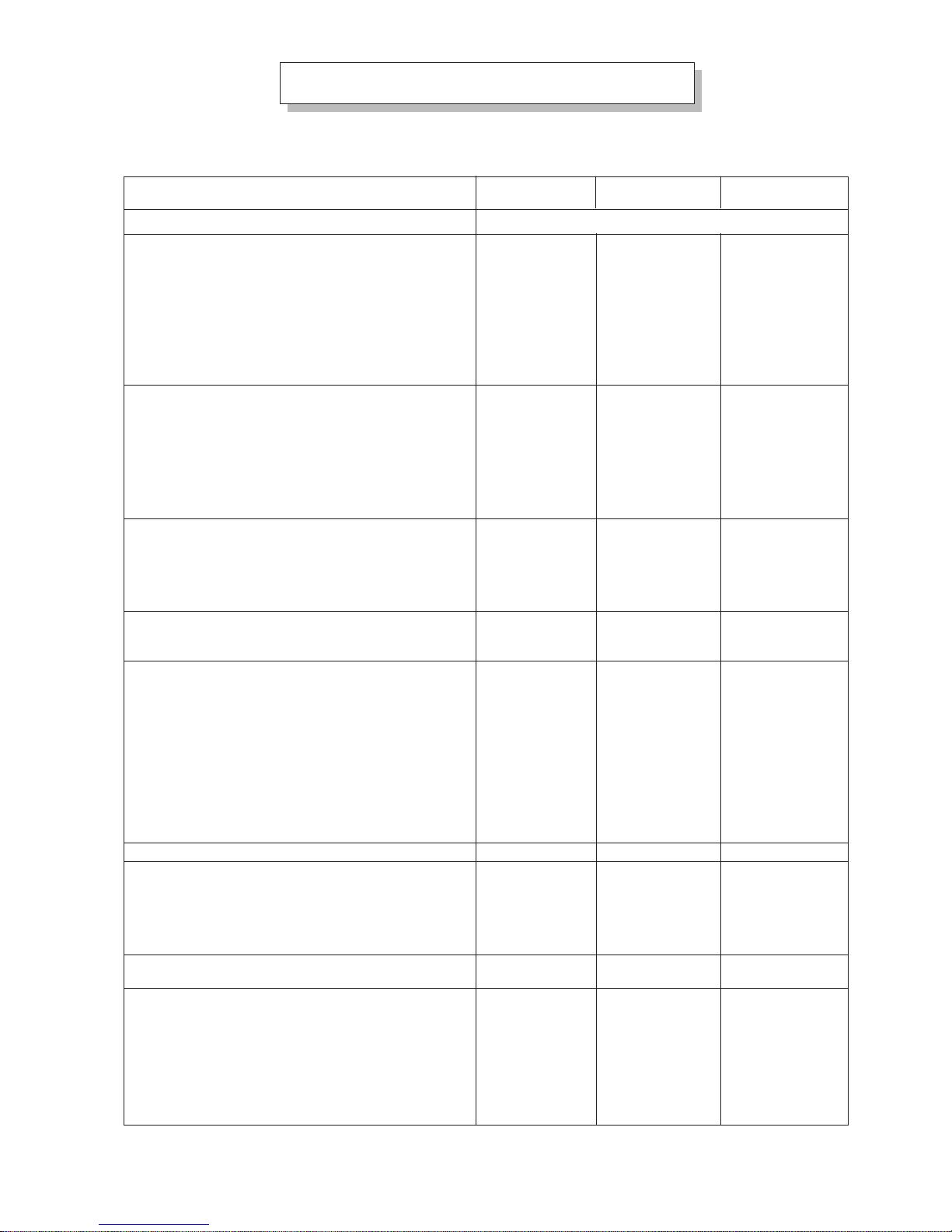
2. TECHNICAL DATA
2.1 GAS APPLIANCES
MODEL
Standards
Outside dimensions
Width
Depth
Height
Height
Full height type A
Full height type B
Outlet type A
Outlet type B
Net weight
Cooking chamber dimensions
Width
Depth
Height
Useful volume
Capacity No. Grilles GN 1/1-2/1
Oven load capacity
Guide c/c distance GN 1/1
Tray depth
Power supply voltage
AC 230 V 50 Hz (or 60 Hz)
External residual
current device
T otal absorbed electric power
Motor absorbed electric power
Power supply
Power supply cable type H07RN-F
Cable no. 3 wires Cross-section
Class according to EN 203 part 1
Outlet type
Nom. outlet diameter
Height type A
Height type B
Nominal heat capacity (min-max)
Gas consumption (15°C)
G30 - 29/50 mbar
G31 - 30/37/50/67 mbar
G20 - 20 mbar
G25 - 25 mbar
Gas supply
W ater supply
Softened water (min÷max)
Consumption
Steam generation
Steam elimination
* NB : 1 bar = 100 kPa
W aste water outlet
T emperature
Oven performance
Oven air temperature range
Steam temperature range
Core probe temperature range
Time to reach 200°C
Consumption to keep average 180°C
Fan speed
868
746
720
807
1097
1237
100
110
120
590
335
430
85
6/18
60
20
x
10
0.55
0.5
1.5
II
A or B
100/110
290
430
8/11.4
0.897
0.885
1.21
1.40
G 3/4”
G 3/4”
0.5÷4
7.5
90
40
100
20 ÷ 270
20 ÷ 100
20 ÷ 99
7
1.8
1400
2800
mm
mm
min.mm
max.mm
max.mm
max.mm
Ø mm
Ø mm
kg
mm
mm
mm
dm
3
max.kg
mm
min.mm
A/ph
kW
kW
mim.mm
2
Ø mm
mm
mm
kW
kW
kg/h
kg/h
m
3
/h
m
3
/h
“R”
min÷max bar*
l/h
l/h
Ø mm
max.°C
°C
°C
°C
min.
kWh
min.g/min
max.g/min
EN 437 and EN 203 part 1
EN 60335 - I and EN 60335 - II - 42
FGMD67
FGMD67SC
FGMD107
FGMD107SC
Gas
Electric
940
900
1045
1095
1365
1575
130
150
175
640
465
670
199
10/-
30÷40
60
20
x
10
0.65
0.6
1.5
II
A or B
130/150
270
480
11.2/15.5
1.26
1.243
1.694
1.97
G 3/4”
G 3/4”
0.5÷4
10
140
40
100
20 ÷ 270
20 ÷ 100
20 ÷ 99
8
2.1
700
1400
1340
995
960
1010
1270
1525
160
180
250
638
850
670
363
10-20
60÷80
60
20
x
10
0.7
0.65
1.5
II
A or B
160/180
260
515
19.6/28.0
2.205
2.175
2.964
3.447
G 3/4”
(2x) G 3/4”
0.5÷4
15
140
40
100
20 ÷ 270
20 ÷ 100
20 ÷ 99
5.7
4.0
700
1400
FGMD207
FGMD207SC
- 5 -
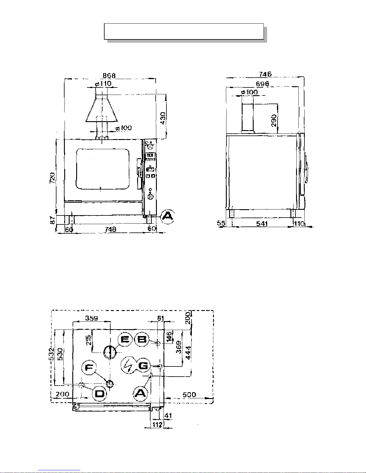
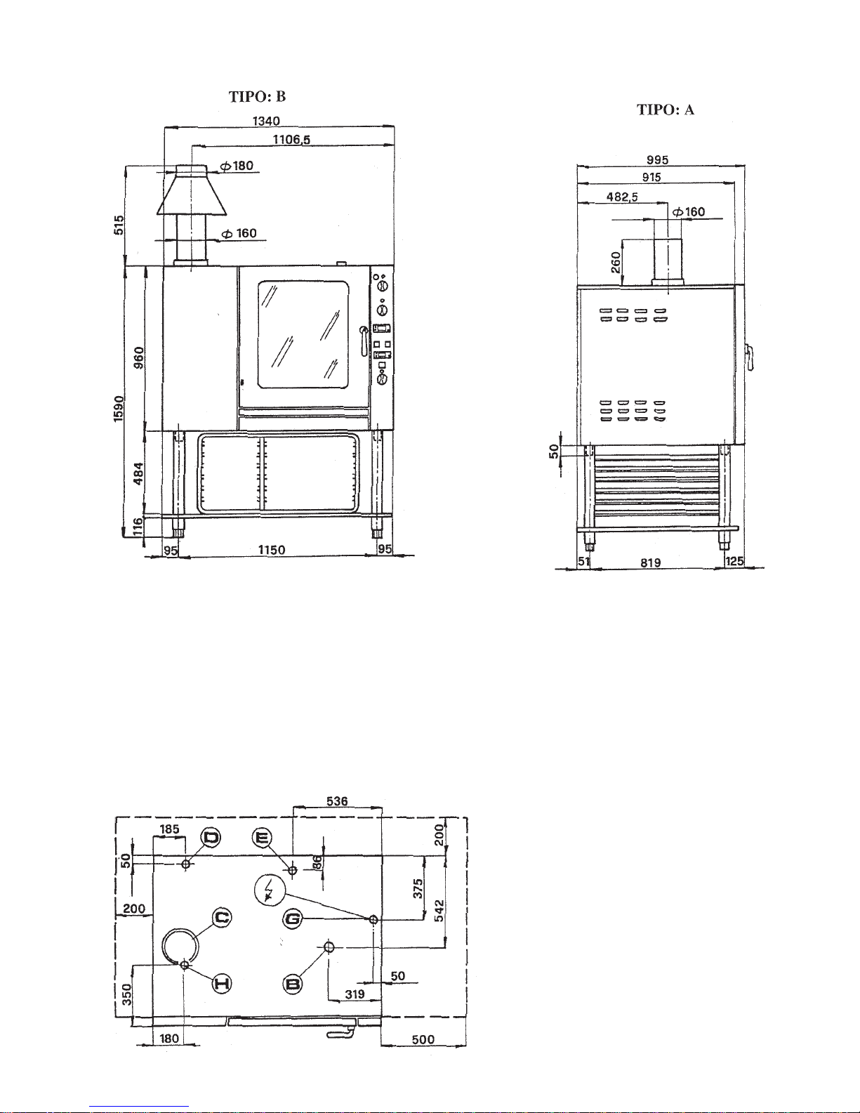
3. INSTALLATION DIAGRAMS
3.1 DIRECT ”COMBINED” GAS OVEN FGMD67/FGMD67SC
B) Softened water inlet G 3/4”
D) Water outlet Ø 40 mm
F) Vent pipe Ø 50 mm
G) Power supply cable input
A) Gas connection G 3/4”
E) Chamber flue Ø 100 mm

- 6 -
DIRECT “COMBINED” GAS OVEN FGMD107/FGMD107SC
B) Softened water inlet G 3/4”
D) Water outlet Ø 40 mm
F) Vent pipe Ø 50 mm
G) Power supply cable input
A) Gas connection G 3/4”
E) Chamber flue Ø 130 mm
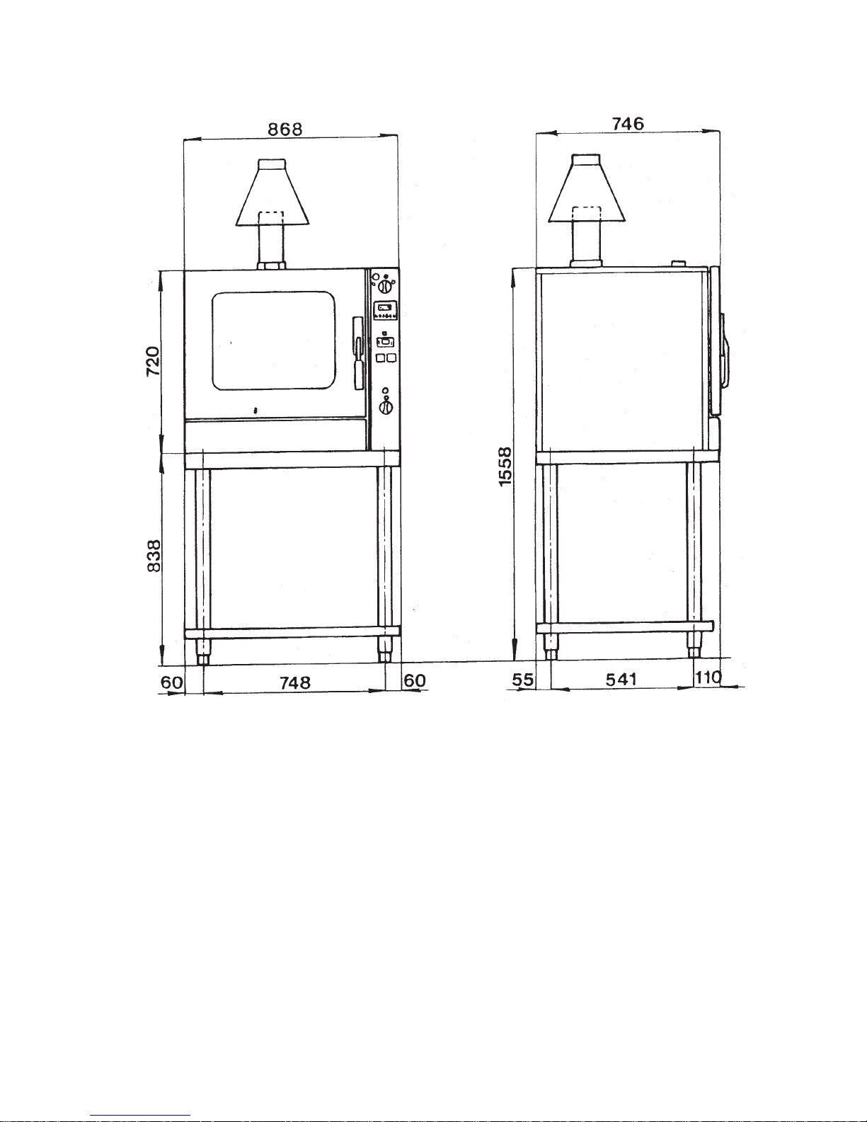
- 7 -
3.2 DIRECT ”COMBINED” GAS OVEN FGMD67/FGMD67SC WITH STAND SF3
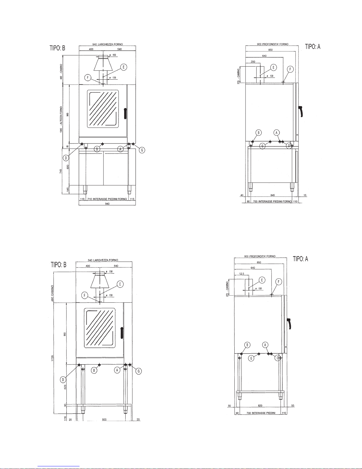
- 8 -
3. 3 DIRECT “COMBINED” GAS OVEN FGMD107/FGMD107SC
WITH CABINET SFA - SFRU
DIRECT “COMBINED” GAS OVEN FGMD107/FGMD107SC WITH STAND SFCV
A) Gas connection G 3/4”
B) Softened water inlet G 3/4”
D) W ater outlet Ø 40 mm
E) Chamber flue Ø 130 mm
F) Vent pipe Ø 50 mm
G) Power supply cable entry
A) Gas connection G 3/4”
B) Softened water inlet G 3/4”
D) W ater outlet Ø 40 mm
E) Chamber flue Ø 130 mm
F) Vent pipe Ø 50 mm
G) Power supply cable entry
- 9 -
3.4 DIRECT ”COMBINED” GAS OVEN FGMD207/FGMD207SC WITH STAND SF2
E) Water outlet Ø 40 mm
G) Power supply cable input
B) Adjustable top condensate outlet Ø 50 mm
C) Chamber flue Ø 160 mm
D) Humidifier water and steam
reduction inlet G 3/4”
H) Gas connection G 3/4”
- 10 -
4. INSTALLATION INSTRUCTIONS
Installation and adjustment operations are to be carried out by qualified personnel according to the norms in force.
(See technical specification tables on page 4).
WARNINGS:
- If the oven is installed against a wall, the wall needs to withstand temperatures of 80°C and must be incombustible.
- Inlets (water and electricity) and outlets (waste water, steam etc.) are signalled by dedicated tags.
- The top of the oven is not to be used to store goods!
4.1 PREPARING FOR INSTALLATION
Before proceeding to installation, remove the protective plastic film and eliminate any adhesive residues by means of a
suitable product for cleaning stainless steel.
4.1.1 LAWS, REGULATIONS AND TECHNICAL DIRECTIVES
The following regulations must be observed during installation:
- Fire regulations.
- Current accident-prevention regulations.
- The regulations of the gas board.
- “Gas system installation” standards.
- “Electric system installation” standards.
- The regulations of the electricity board.
- The regulations of the water board.
- Local ”municipal” norms on the drainage of waste water.
- Health regulations.
- Italian law no.46 05/03/1990.
- Safety standards UNI-CIG 8723 and Italian Ministerial Decree D.M. no. 74 dated 12/04/96.
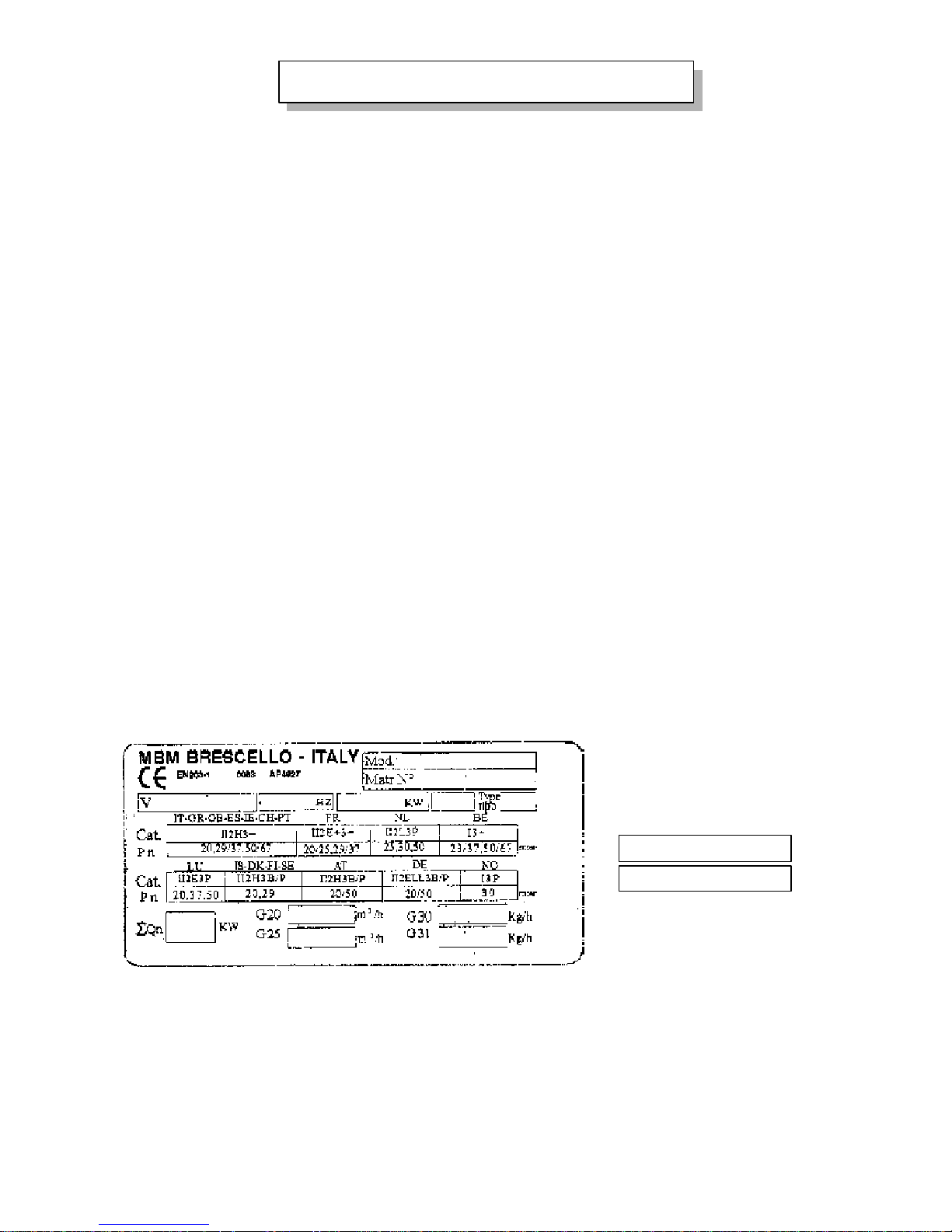
4.1.2 PLATE TO E.U. STANDARDS
TO STANDARDS EN 437 and EN 203 Part 1
ADHESIVE PLATES
GAS FITTING
G 20 20 mbar
G 30/31 29/37 mbar
 Loading...