

Page 1
Title
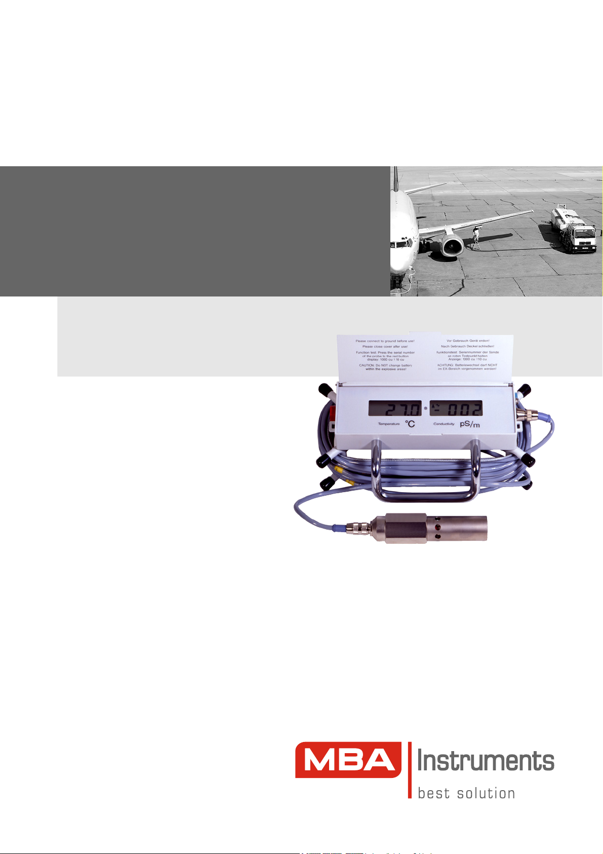
MLA 900
Conductivity meter
for light petroleum products
Operation
Maintenance
Approvals
Operating Instructions
Page 2
Document information
Document ID
Title: Operating Instructions MLA 900
Order No.: 8011381
Version: 2.0
Status: 2010-06
Subject
Product name: MLA 900
Software: Version 1.1
Manufacturer
MBA Instruments GmbH
Friedrich-List-Str. 7 · D-25451 Quickborn · Germany
Phone: +49 (0) 41 06 123 888-0
Fax: +49 (0) 41 06 123 888-9
E-Mail: [email protected]
Trademarks
IBM is a trademark of the International Business Machine
Corporation.
MS-DOS and Windows are trademarks of the Microsoft
Corporation.
Other product names used in this document may also be
trademarks and are only used for identification purpose.
© MBA Instruments GmbH. All rights reserved.
Warning symbols
Hazard (general)
Hazard in explosion-hazardous locations
Hazard by explosive substances/mixtures
Warning levels / signal words
GEFAHR
Immediate hazard which will result in serious injury or death.
WARNUNG
Risk or hazardous situation which could result in serious injury or
death.
VORSICHT
Hazard or unsafe practice which may result in minor or moderate
personal injury.
NOTICE
Hazard or unsafe practice which could result in property
damage.
Information symbols
Important technical information for this product
Nice to know
Supplementary information
Link to information at another place
2
Operating Instructions 8011381 V2.0 © MBA Instruments GmbH
Page 3

Contents
Contents
1 For your own safety … . . . . . . . . . . . . . . . . . . . . . . . . . . . . . . . . . . . . . . . . . . . . . . 5
1.1 General safety in hazardous locations . . . . . . . . . . . . . . . . . . . . . . . . . . . . . . . . . . . . . . . . . 6
1.2 Essential safety notes for the MLA 900 . . . . . . . . . . . . . . . . . . . . . . . . . . . . . . . . . . . . . . . . . 6
2 Notes on application . . . . . . . . . . . . . . . . . . . . . . . . . . . . . . . . . . . . . . . . . . . . . . . . . 7
2.1 Approved use . . . . . . . . . . . . . . . . . . . . . . . . . . . . . . . . . . . . . . . . . . . . . . . . . . . . . . . . . . . . . . . . 8
2.1.1 Designated use . . . . . . . . . . . . . . . . . . . . . . . . . . . . . . . . . . . . . . . . . . . . . . . . . . . . . . . . . . . . 8
2.1.2 Application restrictions. . . . . . . . . . . . . . . . . . . . . . . . . . . . . . . . . . . . . . . . . . . . . . . . . . . . . . 8
2.1.3 Regulations and standards fulfilled. . . . . . . . . . . . . . . . . . . . . . . . . . . . . . . . . . . . . . . . . . . 9
2.2 Official approval . . . . . . . . . . . . . . . . . . . . . . . . . . . . . . . . . . . . . . . . . . . . . . . . . . . . . . . . . . . . . . 9
2.2.1 Definitions of terms. . . . . . . . . . . . . . . . . . . . . . . . . . . . . . . . . . . . . . . . . . . . . . . . . . . . . . . . . 9
2.2.2 Approval for the MLA 900 . . . . . . . . . . . . . . . . . . . . . . . . . . . . . . . . . . . . . . . . . . . . . . . . . . 10
3 Preparing for operation . . . . . . . . . . . . . . . . . . . . . . . . . . . . . . . . . . . . . . . . . . . .11
3.1 Supply schedule. . . . . . . . . . . . . . . . . . . . . . . . . . . . . . . . . . . . . . . . . . . . . . . . . . . . . . . . . . . . . 12
3.2 Assembly . . . . . . . . . . . . . . . . . . . . . . . . . . . . . . . . . . . . . . . . . . . . . . . . . . . . . . . . . . . . . . . . . . . 13
4 Handling. . . . . . . . . . . . . . . . . . . . . . . . . . . . . . . . . . . . . . . . . . . . . . . . . . . . . . . . . . . . . . . . 15
4.1 Display unit . . . . . . . . . . . . . . . . . . . . . . . . . . . . . . . . . . . . . . . . . . . . . . . . . . . . . . . . . . . . . . . . . 17
4.1.1 Handling . . . . . . . . . . . . . . . . . . . . . . . . . . . . . . . . . . . . . . . . . . . . . . . . . . . . . . . . . . . . . . . . . 17
4.1.2 Switching on and off. . . . . . . . . . . . . . . . . . . . . . . . . . . . . . . . . . . . . . . . . . . . . . . . . . . . . . . 17
4.1.3 Measuring value displays . . . . . . . . . . . . . . . . . . . . . . . . . . . . . . . . . . . . . . . . . . . . . . . . . 17
4.2 Fault/limit value displays . . . . . . . . . . . . . . . . . . . . . . . . . . . . . . . . . . . . . . . . . . . . . . . . . . 19
4.3 Performance test . . . . . . . . . . . . . . . . . . . . . . . . . . . . . . . . . . . . . . . . . . . . . . . . . . . . . . . . . . . 21
4.4 Measuring procedure . . . . . . . . . . . . . . . . . . . . . . . . . . . . . . . . . . . . . . . . . . . . . . . . . . . . . . . . 23
4.5 Measures in the event of a fault/damage . . . . . . . . . . . . . . . . . . . . . . . . . . . . . . . . . . . . .24
5 Maintenance . . . . . . . . . . . . . . . . . . . . . . . . . . . . . . . . . . . . . . . . . . . . . . . . . . . . . . . . . . 25
5.1 Cleaning. . . . . . . . . . . . . . . . . . . . . . . . . . . . . . . . . . . . . . . . . . . . . . . . . . . . . . . . . . . . . . . . . . . . 27
5.1.1 Cleaning the probe cable . . . . . . . . . . . . . . . . . . . . . . . . . . . . . . . . . . . . . . . . . . . . . . . . . . 27
5.1.2 Cleaning the measuring probe. . . . . . . . . . . . . . . . . . . . . . . . . . . . . . . . . . . . . . . . . . . . . .27
5.1.3 Cleaning the display unit . . . . . . . . . . . . . . . . . . . . . . . . . . . . . . . . . . . . . . . . . . . . . . . . . . . 27
5.2 Battery . . . . . . . . . . . . . . . . . . . . . . . . . . . . . . . . . . . . . . . . . . . . . . . . . . . . . . . . . . . . . . . . . . . . . 29
5.3 Spare parts . . . . . . . . . . . . . . . . . . . . . . . . . . . . . . . . . . . . . . . . . . . . . . . . . . . . . . . . . . . . . . . . 30
6 Storage, transport . . . . . . . . . . . . . . . . . . . . . . . . . . . . . . . . . . . . . . . . . . . . . . . . . . . 31
6.1 Correct storage . . . . . . . . . . . . . . . . . . . . . . . . . . . . . . . . . . . . . . . . . . . . . . . . . . . . . . . . . . . . . 32
6.2 Short-distance transports. . . . . . . . . . . . . . . . . . . . . . . . . . . . . . . . . . . . . . . . . . . . . . . . . . . . . 32
6.3 Correct shipping. . . . . . . . . . . . . . . . . . . . . . . . . . . . . . . . . . . . . . . . . . . . . . . . . . . . . . . . . . . . . 32
6.4 Shipping for repair . . . . . . . . . . . . . . . . . . . . . . . . . . . . . . . . . . . . . . . . . . . . . . . . . . . . . . . . . . . 33
7 Approval certificate . . . . . . . . . . . . . . . . . . . . . . . . . . . . . . . . . . . . . . . . . . . . . . . . .35
MLA 900 Operating Instructions V 2.0 8011381 © MBA Instruments GmbH 3
Page 4

Contents
4 MLA 900 Operating Instructions V 2.0 8011381 © MBA Instruments GmbH
Page 5

For your own safety …
MLA 900
1 For your own safety …
General safety
Essential safety notes
MLA 900 Operating Instructions V 2.0 8011381 © MBA Instruments GmbH 5
Page 6
For your own safety …
1.1
General safety in hazardous locations
WARNUNG:
b
Before using the instrument for the first time in a hazardous location:
Observe all the safety instructions in these operating instructions.
1.2 Essential safety notes for the MLA 900
b
Observe the following safety notes when assembling and operating the instrument,
during maintenance and repair, and when exchanging parts – for your own protection.
The most important safety rules are:
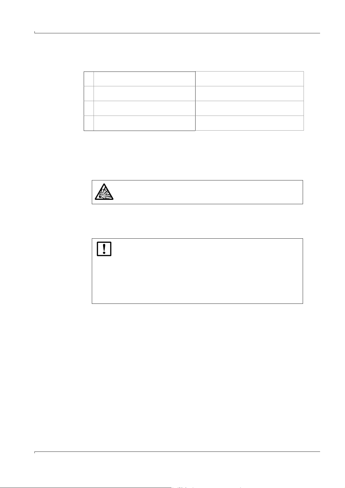
VORSICHT: Risk of wrong measurements
b
Before using the MLA 900: carry out a performance test (→S. 21, §4.3) –
always to be done outside of the hazardous locations.
WARNUNG: Hazard when potential equalisation is missing:
b
Before the measuring probe is lowered into the liquid container: Safely
connect the ground clamp of the display unit with the liquid container
(potential equalisation).
WARNUNG: Hazard when enclosure is open
b
Never open the instrument enclosure as long as it is in a hazardous
location.
WARNUNG: Hazard by unsafe instrument
b
If there is any reason to assume that the instrument is no longer safe: shut
down the instrument and protected it against unauthorised use.
6 MLA 900 Operating Instructions V 2.0 8011381 © MBA Instruments GmbH
Page 7

Notes on application
MLA 900
2 Notes on application
Designated use
Application restrictions
Official approval
MLA 900 Operating Instructions V 2.0 8011381 © MBA Instruments GmbH 7
Page 8
Notes on application
2.1
2.1.1 Designated use
Approved use
Measuring function
The MLA 900 determines the electrical conductivity and the temperature of petroleum
products such as occur, for example, in aviation fuels and in other petroleum products.
During the filling process, pumping or filtering, these liquids may become electrostatically
charged. If, in addition, there is an inflammable gas mixture present in the ambient
atmosphere, there is a danger that the gas mixture will be ignited by a discharge spark,
which means that it may explode. To evaluate this risk, the electrical conductivity of the
liquid is measured (see German standard DIN 51 412-T02-79, »Determining electrical
conductivity, field procedure«).
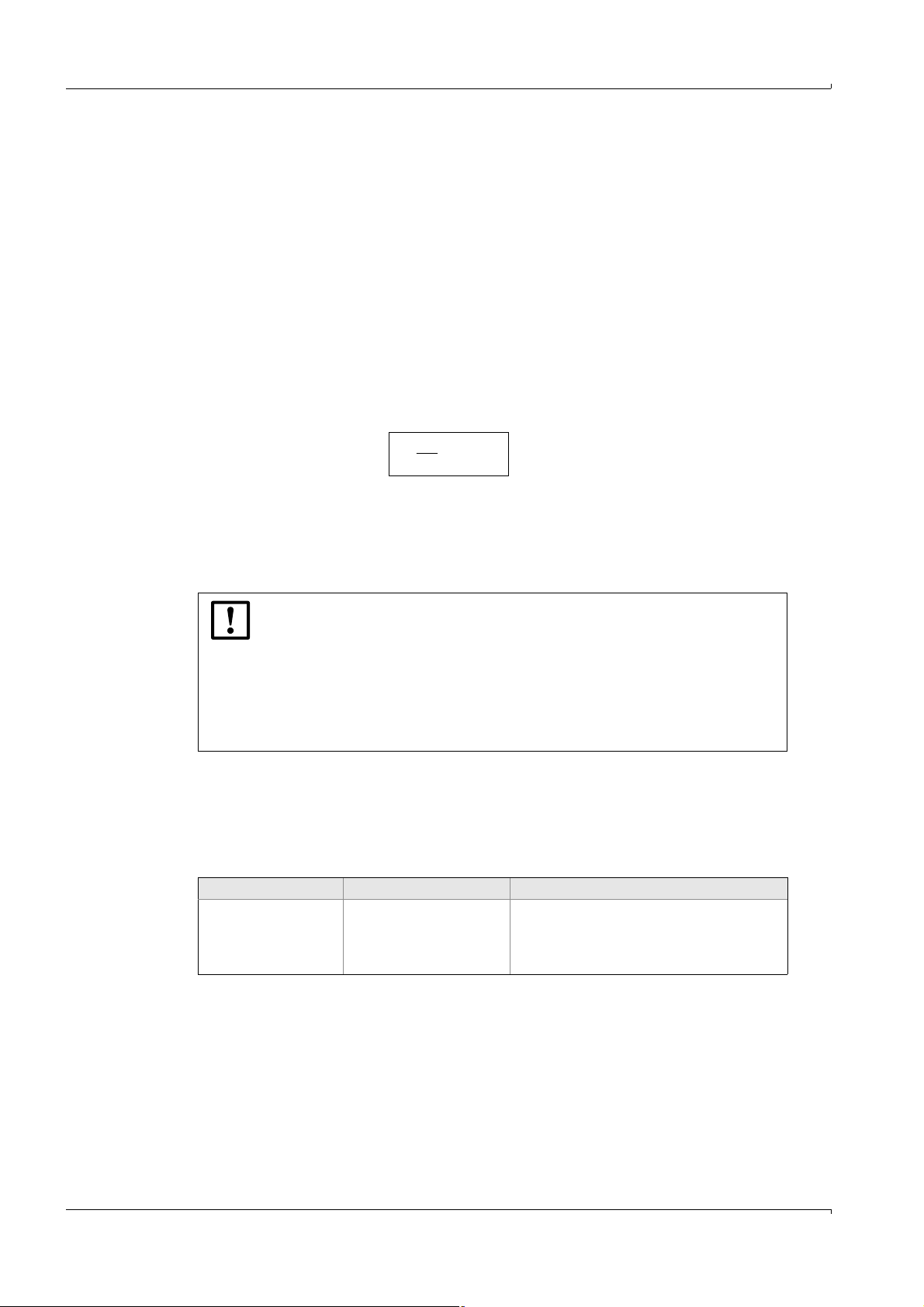
The conductivity is stated in the physical unit »pS/m« (picosiemens per meter). This unit
corresponds to »c.u.« (conductivity unit), which is still commonly used in the petroleum
industry:
Ambient conditions
The MLA 900 is designed as a measuring instrument for outside use.
b
Use the MLA 900 at an ambient temperature of –20 °C … +60 °C (–4 … +140 °F).
Outside this temperature range it can no longer be guaranteed that the instrument will
function correctly.
pS
1
1c.u.=
m
● At temperatures above +60 °C (140 °F) there is a danger that caustic liquid
from the battery may escape and damage the electronics. Apart from this,
the LC displays may be damaged (irreversible blackening).
● At temperatures of below –20 °C (–4 °F), the LC displays in the display unit
may freeze, resulting in the LC display enclosure bursting.
● Low temperatures affect the flexibility of the probe cable.
b
Avoid bending the probe cables in low temperatures.
Otherwise the probe cable could brake due to the sheath becoming brittle.
2.1.2 Application restrictions
The MLA 900 may only be used to measure the conductivity and temperature of petroleum
products, such as petrol, kerosene and oils/greases. Other liquids such as acids or
solvents containing chlorinated hydrocarbons, for example, can damage the measuring
probe.
component clean with avoid contact with
measuring probe
probe cables
petrol
spirit (ethanol)
isopropanol
acids
chlorinated hydrocarbons (CHC)
methanol
acetone
8 MLA 900 Operating Instructions V 2.0 8011381 © MBA Instruments GmbH
Page 9

Notes on application
2.1.3
Regulations and standards fulfilled
The MLA 900 measuring procedure corresponds to:
● German standard DIN 51 412-T02-79 (»Determining electrical conductivity, field
procedure«)
● ASTM 02624 »Standard Test Methods for Electrical Conductivity of Aviation and
Distaillate Fuels«
The technical design of the MLA 900 corresponds to:
● European standard EN 60079-0:2006
● European standard EN 60079-11:2007
● European standard EN 60079-26:2007
● European Council Directrive 94/9/EC (ATEX guideline)
● German »Ordinance on electrical appliances in hazardous locations« (»Verordnung
über elektrische Anlagen in explosionsgefährdeten Räumen«, ElexV) of 13 December
1996.
2.2 Official approval
2.2.1 Definitions of terms
● An explosive mixture is a mixture of gases, vapours, mists or dusts in which a reaction
continues independently after ignition.
● An explosive atmosphere contains explosive mixtures of gases, vapours, mists or dusts
with air, including usual admixtures (for example, humidity) under atmospheric
conditions. Atmospheric conditions are here defined as total pressures of 0.8 to 1.1 bar
and gas mixture temperatures of from –20 °C to +60 °C.
A dangerous explosive atmosphere occurs when in the event of an ignition injury may
be caused to persons as a direct or indirect result of the explosion.
● Hazardous locations are those areas in which a dangerous explosive atmosphere may
occur due to local and operational conditions.
Hazardous locations are divided into zones on the basis the probability (in terms of time
and place) of the presence of dangerous explosive atmospheres:
– Zone 0 includes areas in which a dangerous explosive atmosphere is present
»constantly or for longer periods«; for example, in tank facilities.
– Zone 1 covers areas in which a dangerous explosive atmosphere »occasionally«
occurs; for example, in the vicinity of refuelling nozzles.
MLA 900 Operating Instructions V 2.0 8011381 © MBA Instruments GmbH 9
Page 10
Notes on application
2.2.2
Approval for the MLA 900
Approved area of application
The MLA 900 is approved for use in hazardous locations in which inflammable gases,
vapours or mists may occur (EEx ia IIB T6). The MLA 900 measuring probe is approved for
use in Zone 0, the display unit for use in Zone 1.
Prescribed operating conditions
The following applies for the use of the MLA 900 conductivity meter in the area of
application as defined in the »Ordinance on electrical appliances in hazardous locations
(ElexV)«:
WARNUNG: Hazards in explosions-hazardous locations
● The MLA 900 is intended exclusively for mobile use at different locations.
● The measuring probe of the MLA 900 is approved for use in containers for
inflammable liquids (Hazardous Location Zone 0).
● The display unit of the MLA 900 may only be used in Hazardous Location
Zone 1.
● The measuring probe may only be used in such liquids against which the
→
materials of which it is made offer adequate chemical resistance (
§2.1.2).
● Damaged measuring probes may not be used in Zone 0.
● Before the measuring probe is taken to Zone 0, all plug and threaded cable
connections must be checked.
● The measuring probe may only be used with the appropriate display unit.
● Before the measuring probe is lowered into the liquid container (tank), the
ground clamp of the display unit must be connected to the container to
equalize the electric potentials.
S. 8,
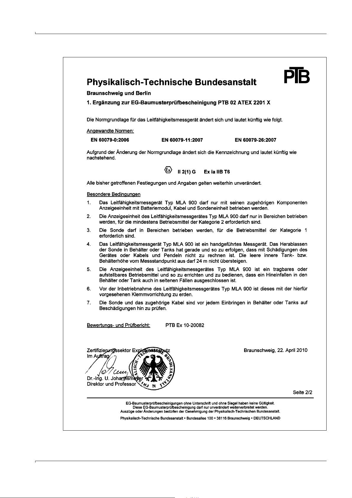
Approval document →S. 36
10 MLA 900 Operating Instructions V2.0 8011381 © MBA Instruments GmbH
Page 11

Preparing for operation
MLA 900
3 Preparing for operation
Supplied parts
Assembly
MLA 900 Operating Instructions V 2.0 8011381 © MBA Instruments GmbH 11
Page 12
Preparing for operation
Nr.: 930XXX
PTB02ATEX2201X
3.1
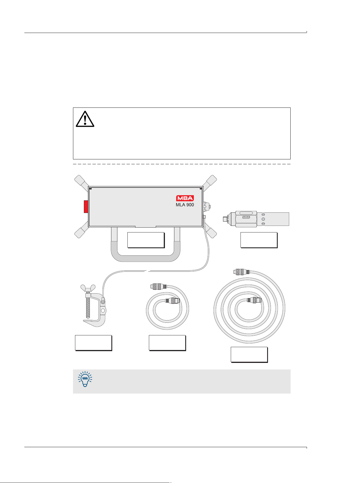
Supply schedule
When delivered, the MLA 900 consists of:
● display unit with ground clamp
● measuring probe
● probe cable, 2 m long
● probe cable, 10 m long
● transport case
VORSICHT: Risk of damage
● Tight bending may damage the cable (cable breaks).
● Damaged cables must not be used in hazardous locations.
b
Never buckle the probe cable and do not bend the cables too far.
b
At temperatures below 0 °C (32 °F), treat the probe cable with particular
care – because the cable sheath may become brittle at these temperatures.
Avoid tight bending (risk of breakage).
Bild 1 MLA 900 supply schedule
ground clamp
● Keep the transport box even if you do not wish to use it when operating the
● List of spare parts
display unit
probe cable
2m
MLA 900. It may be useful as a shipping packaging.
→
S. 30, §5.3
measuring
probe
probe cable
10 m
12 MLA 900 Operating Instructions V2.0 8011381 © MBA Instruments GmbH
Page 13
Preparing for operation
Nr.: 930XXX
PTB02ATEX2201X
3.2
Assembly
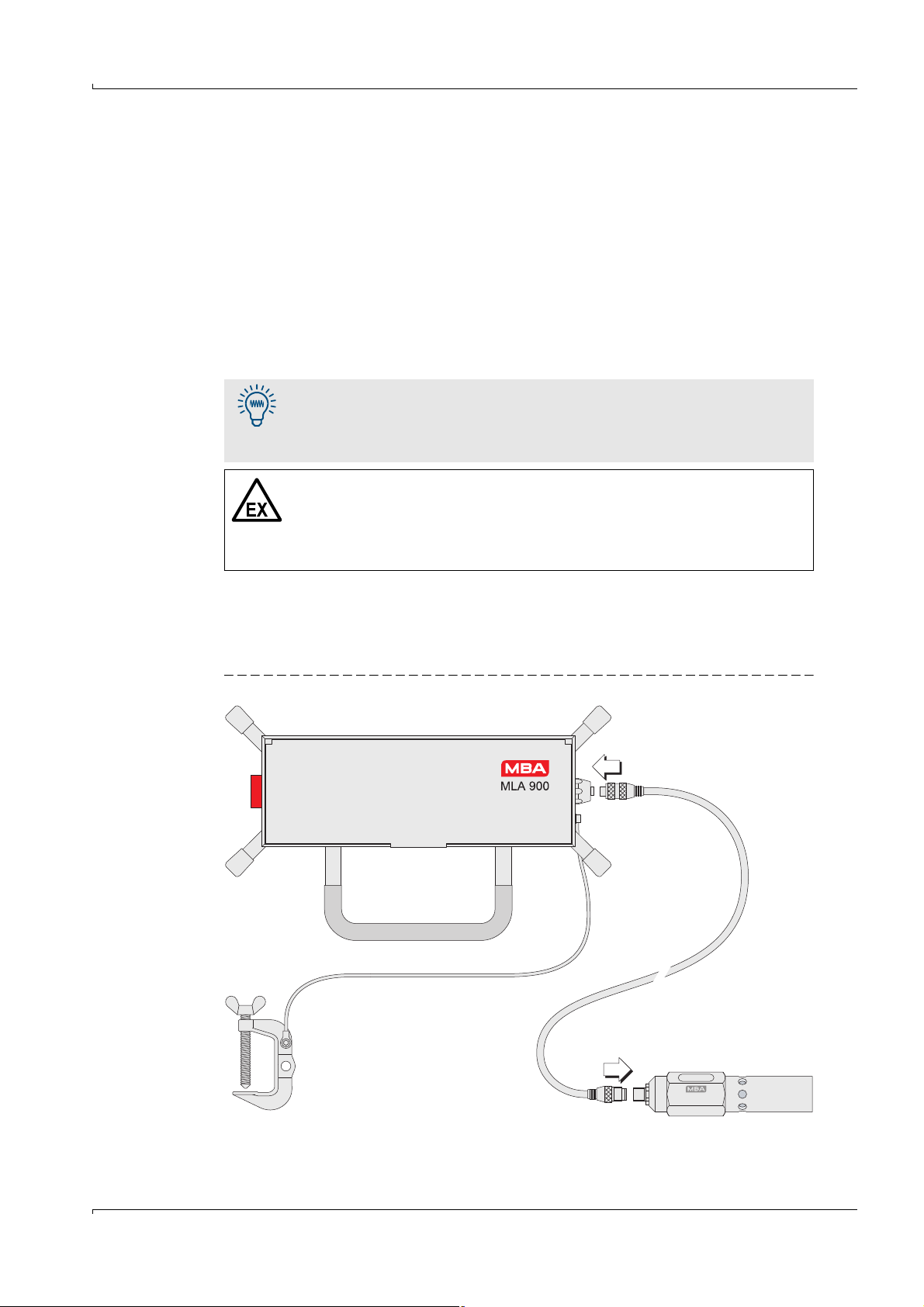
The MLA 900 consists of four instrument components (measuring probe, display unit,
ground clamp, probe cables). – Note: These components will only conform to the technical
safety regulations for the petroleum industry when used as an assembled unit.
Measuring probe and display unit are a matching pair
Display unit and measuring probe have been individually adapted in the factory. If a
different probe is connected, the measuring accuracy cannot be guaranteed.
b
Only connect a measuring probe to a display unit with the identical serial number on it.
Probe cables
b
Connect the display unit to the measuring probe with one of the probe cables supplied.
(Choose the cable length which is the best for the application.)
You can also connect the probe cables to each other to have a 12 m length of
cable. Greater cable lengths can be obtained by using further cable sections
→
(order designations
The maximum allowable total cable length is 24 m.
WARNUNG: Risk by wrong equipment
b
Use only use cables of the type supplied to connect the display unit and the
measuring probe.
It is not permitted to operate the instrument with other cables in hazardous
locations.
Ground clamp
b
Make sure that the ground clamp is firmly attached to the display unit (threaded
connections, cable lugs).
b
Do not start up the MLA 900 if this is not sure.
S. 30, §5.3).
Bild 2 Connecting the probe cable
MLA 900 Operating Instructions V 2.0 8011381 © MBA Instruments GmbH 13
Page 14

Preparing for operation
14 MLA 900 Operating Instructions V2.0 8011381 © MBA Instruments GmbH
Page 15

Handling
MLA 900
4 Handling
Instrument display
Performance test
Measuring procedure
MLA 900 Operating Instructions V 2.0 8011381 © MBA Instruments GmbH 15
Page 16
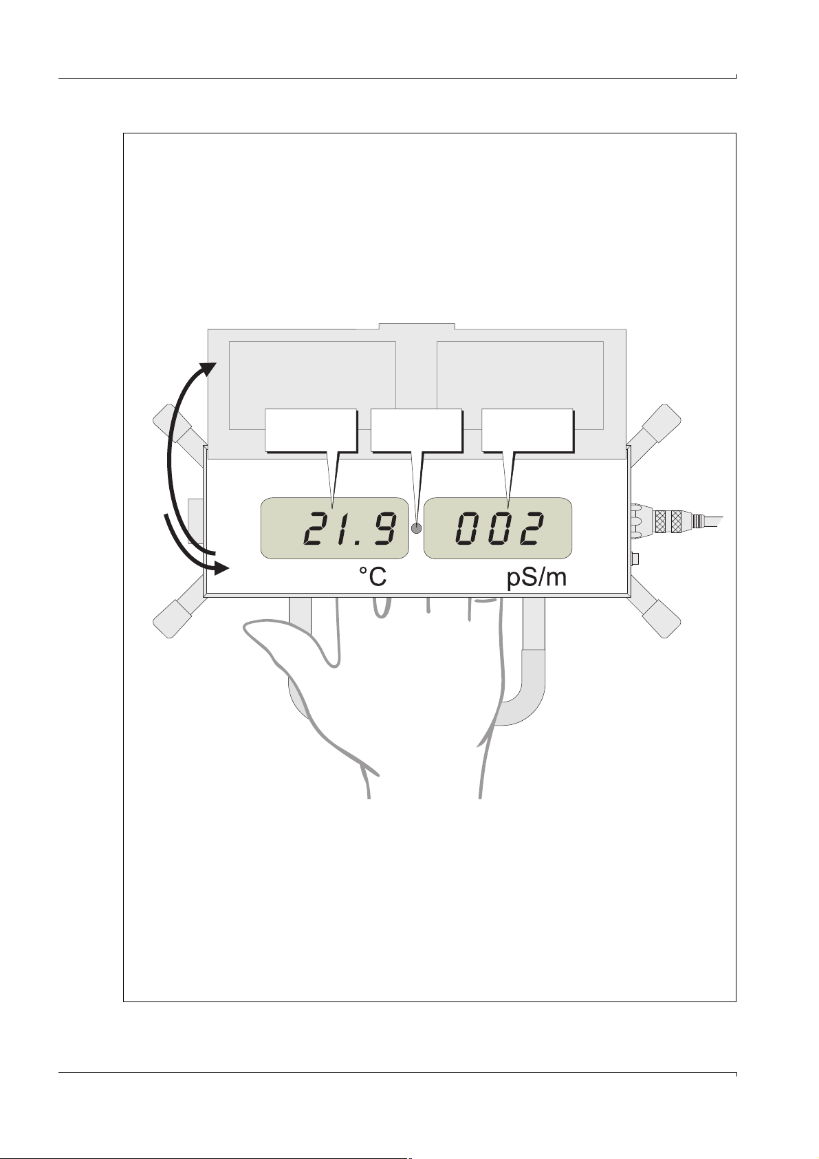
Bild 3 Display unit
Handling
ON
OFF
Please close cover after use!
Function test: Press the serial number
of the probe to to red button
display: 1000 cu + 10 cu
CAUTION: Do NOT change battery
within the explosive areas!
temperature
measured
Temperature
light
sensor
Nach Gebrauch Deckel schlieen!
Funktionstest: Seriennummer der Sonde
an roten Testpunkt halten
Anzeige: 1000 cu + 10 cu
ACHTUNG: Batteriewechsel darf NICHT
im EX-Bereich vorgenommen werden!
conductivity
measured
Conductivity
16 MLA 900 Operating Instructions V2.0 8011381 © MBA Instruments GmbH
Page 17

Handling
4.1
4.1.1 Handling
Display unit
Handling during transport
b
Always use the carrying handle to carry the instrument.
⊗ Do not use the cover flap or the cable brackets to carry the instrument.
Handling during measurement
b
During measurements, hold the display unit safely in your hand.
If you put the display unit down while measuring: make sure that it is standing
securely – because it might be pulled down by the weight of the measuring
probe, or even fall into the liquid container.
WARNUNG: Risks by wrong use
b
In hazardous locations the display unit may only be operated within
»Zone 1«.
b
Before the measuring probe is introduced into the liquid container (tank):
connect the ground clamp of the display unit to the container.
4.1.2 Switching on and off
b
Switching on: Open the cover flap of the display unit.
➝ The MLA 900 automatically starts up when the light sensor is exposed to light.
b
Switching off: Close the cover flap.
➝ When the flap is closed, the MLA 900 automatically shuts off.
4.1.3 Measuring value displays
left-hand display: right-hand display:
temperature of the measuring probe/
the liquid
Display range:
b
Watch out for fault and limit value indications (→S. 19, §4.2).
-199
The MLA 900 is approved for measurement in hazardous locations only in a
temperature range of
the MLA 900 fulfils the stated specifications.
°C … +
conductivity measured
199
°C Measuring range:0…
–20
°C … +60°C. This is the temperature range where
1999
pS/m
MLA 900 Operating Instructions V 2.0 8011381 © MBA Instruments GmbH 17
Page 18
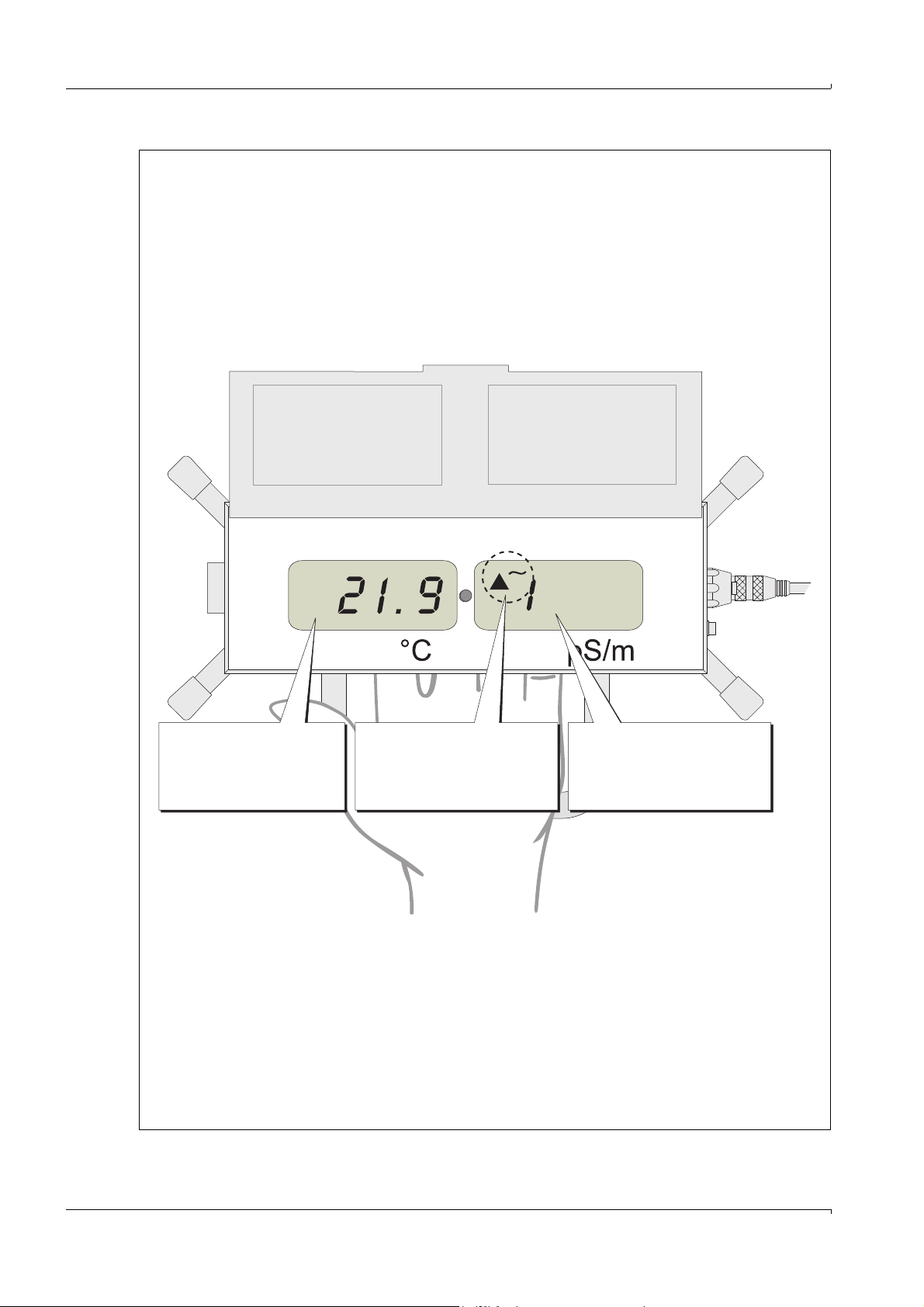
Bild 4 Fault/limit value displays
Handling
Function test: Press the serial number
CAUTION: Do NOT change battery
battery
is almost spent
Please close cover after use!
of the probe to to red button
display: 1000 cu + 10 cu
within the explosive areas!
BAT BAT
Temperature
conductivity measured
is lower than 50 pS/m
Conductivity
– or –
fault
Nach Gebrauch Deckel schlieen!
Funktionstest: Seriennummer der Sonde
an roten Testpunkt halten
Anzeige: 1000 cu + 10 cu
ACHTUNG: Batteriewechsel darf NICHT
im EX-Bereich vorgenommen werden!
measuring range
overflow
(conductivity measured
is greater than 1999 pS/m
18 MLA 900 Operating Instructions V2.0 8011381 © MBA Instruments GmbH
Page 19
Handling
4.2
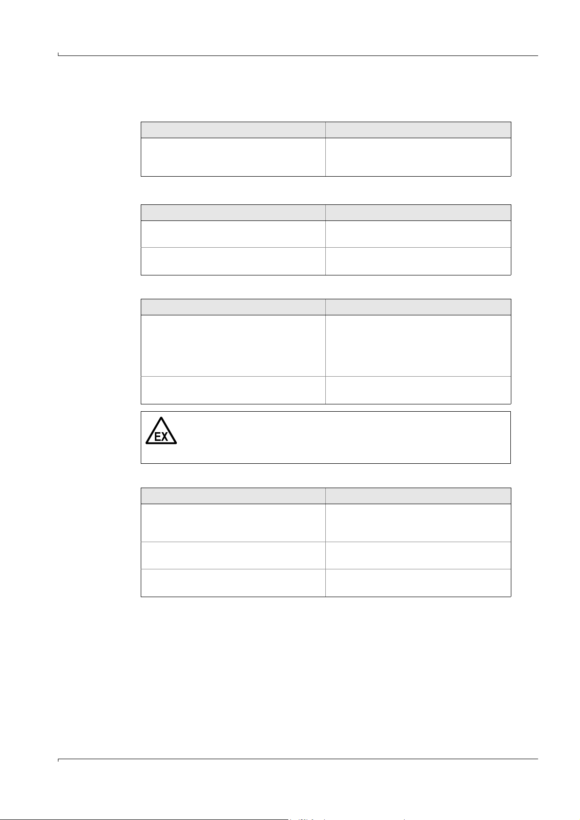
Fault/limit value displays
BAT
(shown on both displays)
Meaning Measures/instructions
The life of the built-in battery is almost over.
b
The battery voltage is lower than 8 V
(new battery: 9 V).
Replace the battery (→S. 29, §5.2).
▲~
Meaning Measures/instructions
b
The measuring probe is outside the liquid.
The conductivity of the sample solution is
50
lower than
▲~
1
xxx + constantly changing temperature measuring valuet
Meaning Measures/instructions
The probe cable is broken.
Measuring probe is badly contaminated or
moist (splashed with water).
pS/m.
Immerse the measuring probe in the
liquid.
b
Observe the safety rules and carry out
the measures laid down for this case.
b
Carry out a performance test (→S. 21,
§4.3).
b
If unsuccessful: change the probe
cable. Then carry out another
performance test.
b
Clean and dry the measuring probe
→
S. 27, §5.1).
(
WARNUNG: Risk by damaged cable
b
Do not operate the instrument in hazardous locations if the probe cable is
damaged or defective.
b
Only change the probe cable outside hazardous locations.
1
Meaning Measures/instructions
b
Measuring value is greater than
1999
Measuring probe is badly contaminated or
moist (splashed with water).
MLA 900 is damaged.
pS/m.
Check whether the conductivity of the
liquid can actually be greater than
1999 pS/m.
b
Clean and dry the measuring probe
→
S. 27, §5.1).
(
b
Carry out a performance test (→S. 21,
§4.3).
MLA 900 Operating Instructions V 2.0 8011381 © MBA Instruments GmbH 19
Page 20
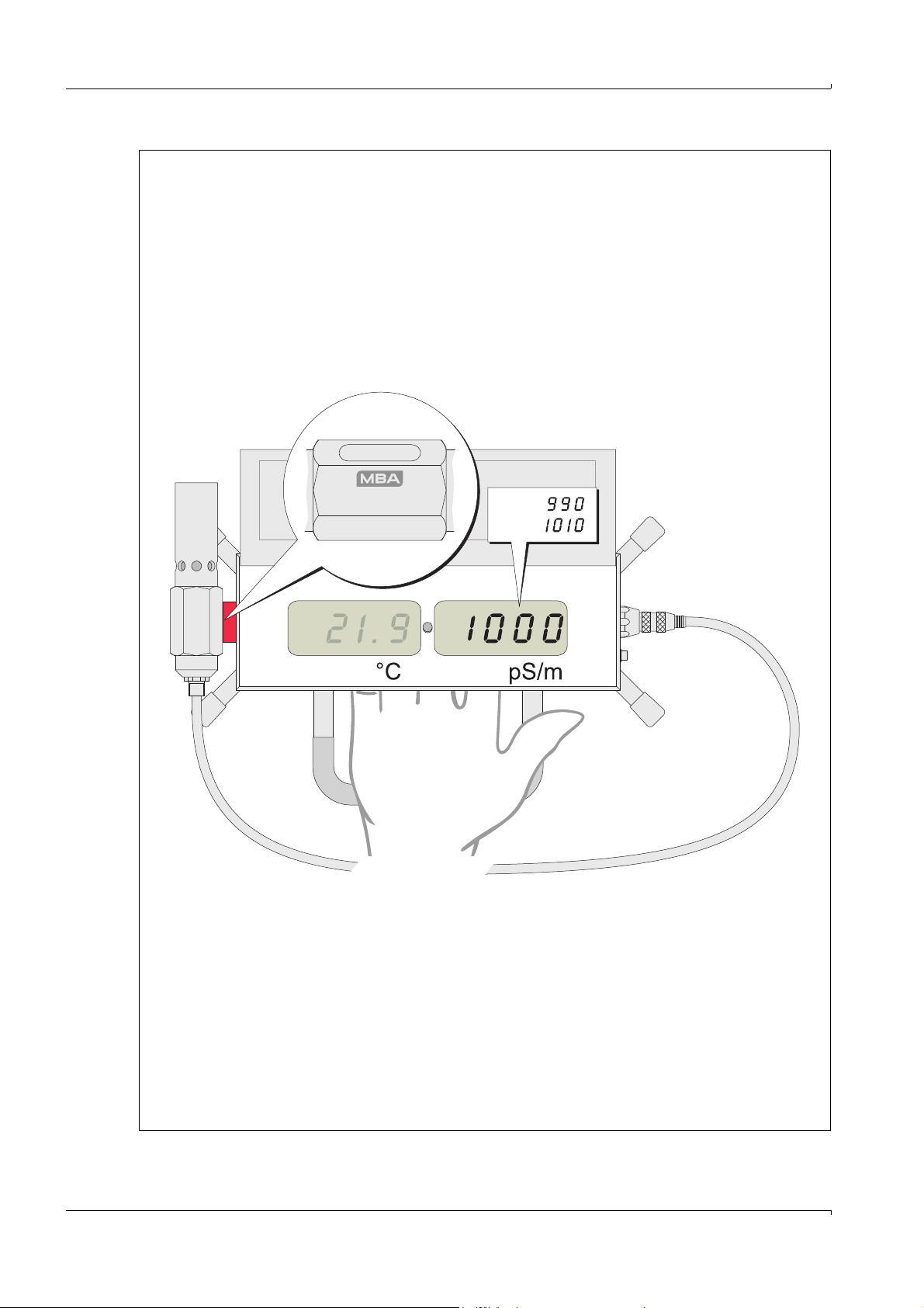
Bild 5 Performance test
Nr.: 930XXX
PTB02ATEX2201X
Handling
Please close cover after use!
Function test: Press the serial number
of the probe to to red button
display: 1000 cu + 10 cu
CAUTION: Do NOT change battery
within the explosive areas!
MLA 900
Temperature
Nach Gebrauch Deckel schlieen!
Funktionstest: Seriennummer der Sonde
an roten Testpunkt halten
Anzeige: 1000 cu + 10 cu
min.
ACHTUNG: Batteriewechsel darf NICHT
im EX-Bereich vorgenommen werden!
max.
Conductivity
20 MLA 900 Operating Instructions V2.0 8011381 © MBA Instruments GmbH
Page 21
Handling
4.3
Performance test
VORSICHT: Risk of wrong measurements
b
Always make a performance test before operating the MLA 900.
b
Perform this performance test outside hazardous locations.
Check condition of instrument
1 Make sure that
– the cylinder of the measuring probe is tightly screwed on
– the measuring probe is sufficiently clean and dry
– display unit and measuring probe are correctly connected to each other (inspect
cables and plug connectors).
Check basic condition
2 Open the cover flap of the display unit in order to switch on the MLA 900. Let the
measuring probe hang free in the air.
➝ The conductivity value measured should then read
b
If a value above 2pS/m is displayed: carefully clean the measuring probe (→S. 27,
§5.1).
b
If a value below
Check measuring function
3 Hold the surface of the measuring probe with the company logo close to the red disc on
the display unit.
➝ The MLA 900 should display
b
If the value is not between
-2
pS/m is displayed: check the battery (→S. 29, §5.2).
1000
990
pS/m (±10 pS/m).
and
1010
-2…2
pS/m: check the battery (→S. 29, §5.2).
pS/m.
A re-calibration (a new adaptation of measuring probe and electronics) is
usually not required. If it is however necessary, this work must be made at the
manufacturer's factory, for safety reasons. Please observe the transport
→
instructions before shipping the instrument (
S. 31, §6).
MLA 900 Operating Instructions V 2.0 8011381 © MBA Instruments GmbH 21
Page 22
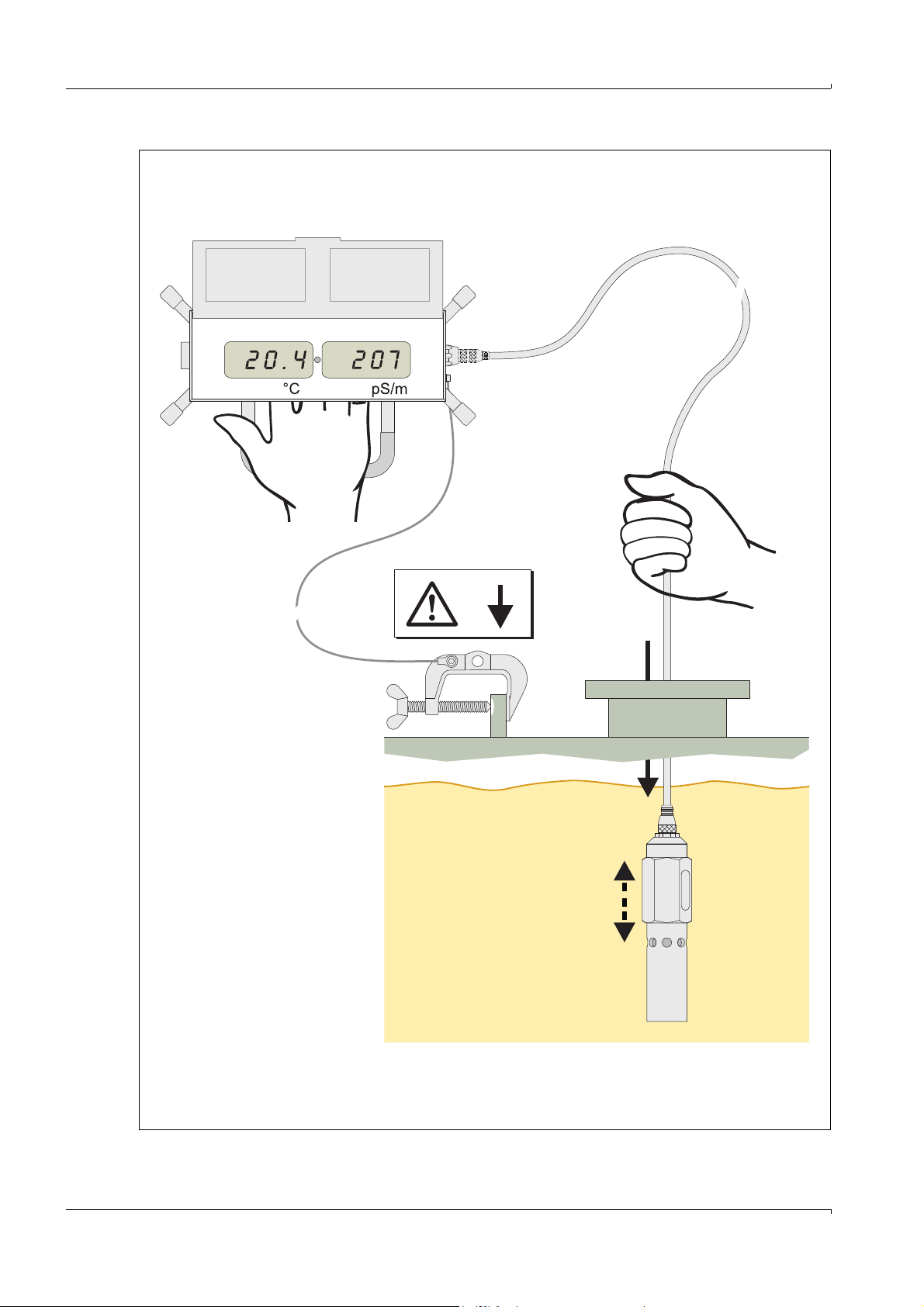
Bild 6 Measuring procedure
Handling
Please close cover after use!
Function test: Press the serial number
of the probe to to red button
display: 1000 cu + 10 cu
CAUTION: Do NOT change battery
within the explosive areas!
Temperature
Nach Gebrauch Deckel schlieen!
Funktionstest: Seriennummer der Sonde
an roten Testpunkt halten
Anzeige: 1000 cu + 10 cu
ACHTUNG: Batteriewechsel darf NICHT
im EX-Bereich vorgenommen werden!
Conductivity
1.
2.
3.
22 MLA 900 Operating Instructions V2.0 8011381 © MBA Instruments GmbH
Page 23
Handling
4.4
Measuring procedure
Checking the instrument
Measuring probe safely connected to
1.
the probe cable?
Cylinder of the measuring probe tightly
2.
screwed on
3. Measuring probe sufficiently clean?
Connection of ground clamp and display
4.
unit in perfect condition?
Measuring
Hold the display unit in your hand or use the transport case for holding the display unit (do
not put the display instrument down!).
1 Connect the ground clamp: Attach the ground clamp to a metallic, unpainted, rust-free
and grease-free point on the liquid container. Make sure that there is a good metallic
connection between the liquid container and the display unit.
WARNUNG: Explosion risk
b
Do not lower the measuring probe into the liquid container before the
ground clamp is safely connected to the container.
2 Immerse the measuring probe: Take the measuring probe and the probe cables out of
the bracket on the display unit and lower the measuring probe, hanging from the cable,
carefully into the liquid.
3 Measure: Open the cover flap of the display unit and read the measuring values. Note:
So that the measuring probe won’t get lost
in the liquid container.
Otherwise wrong measurements and/or
faults could occur (
→
S. 19, §4.2).
Contamination results in wrong measuring
→
results (cleaning
S. 27, §5.1).
Otherwise safety is not guaranteed.
b
Make sure that the measuring probe is completely filled with liquid. Air
bubbles would distort the measuring result.
b
If possible, measure the conductivity just when the desired immersion
depth is reached, or move the measuring probe constantly while
1
measuring.
b
Wait for the final temperature reading until the temperature display
remains approximately constant.
b
Please consider: there can be different temperatures at different
2
depths.
1
If the measuring probe is resting in the liquid, the conductivity measuring value will slowly change, due to
unavoidable electrochemical effects (ionic migration, polarisation, surface effects).
2
This takes about 30 seconds after the immersion; you can speed-up this by constantly moving the measuring
probe.
Finishing the measurement
1 Switch off the MLA 900: Close the cover flap of the display unit.
2 Remove the measuring probe: Pull in the measuring probe carefully out of the liquid
container (recommendation: wipe the probe cable when pulling out and dry with a soft
cloth). Stow the cables and measuring probe in the brackets of the display unit.
3 Stow away the ground clamp: Detach the ground clamp and attach it to the underside
of the display unit.
MLA 900 Operating Instructions V 2.0 8011381 © MBA Instruments GmbH 23
Page 24
Handling
4.5
Measures in the event of a fault/damage
WARNUNG: Risks caused by damage
If a fault or damage to an instrument component is detected, the MLA 900 must
not be taken into a hazardous location.
If the MLA 900 is faulty or damaged:
b
Mark the instrument clearly as faulty (for example, using a sticker).
b
Make sure that the MLA 900 is no longer used in hazardous locations.
WARNUNG: Risk caused by damaged measuring probe
If the cylinder of the measuring probe is deformed (for example, partly dented),
the conductivity measuring values will be distorted. This fault may not be detected
→
during a performance test (
b
Check the mechanical condition of the measuring probe.
b
If the MLA 900 is faulty of damaged: send both the display unit and the measuring
probe to the manufacturer's factory for repair (detailed information
S. 21, §4.3).
→
S. 13, §3.2).
24 MLA 900 Operating Instructions V2.0 8011381 © MBA Instruments GmbH
Page 25

Maintenance
MLA 900
5 Maintenance
Cleaning
Battery replacement
Spare parts
MLA 900 Operating Instructions V 2.0 8011381 © MBA Instruments GmbH 25
Page 26
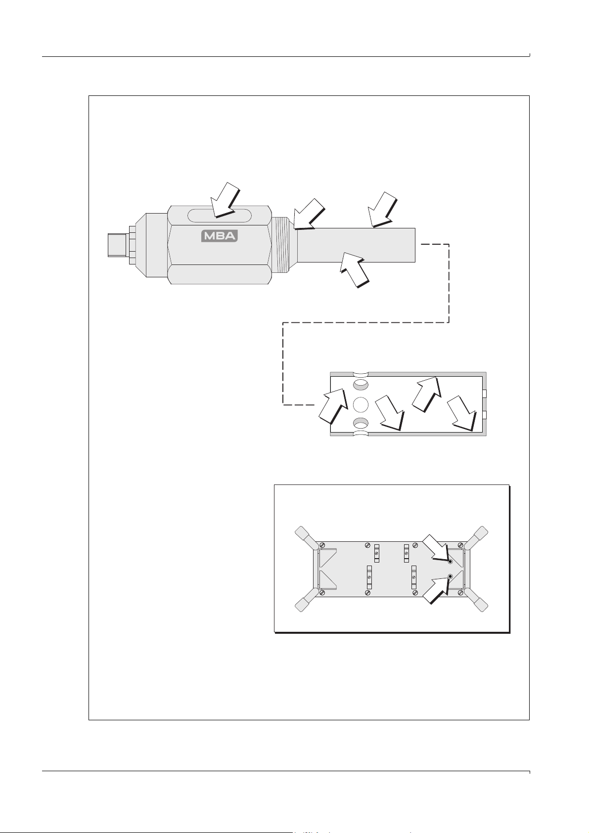
Bild 7 Surfaces of the measuring probe sensitive to contamination
Nr.: 930XXX
PTB02ATEX2201X
Maintenance
26 MLA 900 Operating Instructions V2.0 8011381 © MBA Instruments GmbH
Page 27
Maintenance
5.1
Cleaning
WARNUNG: Hazard in explosion-hazardous locations
b
Perform any cleaning works only outside hazardous locations.
5.1.1 Cleaning the probe cable
b
To clean the probe cable, use a soft cloth moistened with spirits or any other mild
solvent (
b
Make sure that dirt and solvent residue are completely removed.
5.1.2 Cleaning the measuring probe
→
S. 8, §2.1.2).
1 Unscrew the cylinder of the measuring probe.
If you are not able to detach the cylinder by hand: try using the two pins on the
underside of the display unit which fit into the cylinder face.
VORSICHT: Damage risk
⊗ Do not fix the measuring probe’s body or cylinder in a vice.
The pressure from the vice could burst the plastic material in the probe body.
Deformations in the cylinder will cause wrong measuring results.
2 Clean all surfaces of probe body and cylinder carefully with a soft cloth moistened with
→
a »mild« solvent (
S. 8, §2.1.2).
The quality of your next measurement depends on how clean the parts of the
probe are.
VORSICHT: Damage risk
b
Only use solvents which cannot have an aggressive effect on the
measuring probe materials (
b
Make sure that the plastic material is not scratched. Any dirt collecting in
such scratches may affect measuring results.
b
Do not use measuring probes in hazardous locations which have been
damaged or attacked by aggressive solvents.
5.1.3 Cleaning the display unit
b
Regularly clean the enclosure of the display unit with a soft cloth moistened with a mild
cleaning agent or solvent.
b
Use only solvents which cannot attack the enclosure or the print on the display unit
(
→
S. 8, §2.1.2).
VORSICHT: Risk by damage parts
b
If the display unit enclosure has been attacked by solvents: Do not put the
MLA 900 into operation.
→
S. 8, §2.1.2).
MLA 900 Operating Instructions V 2.0 8011381 © MBA Instruments GmbH 27
Page 28
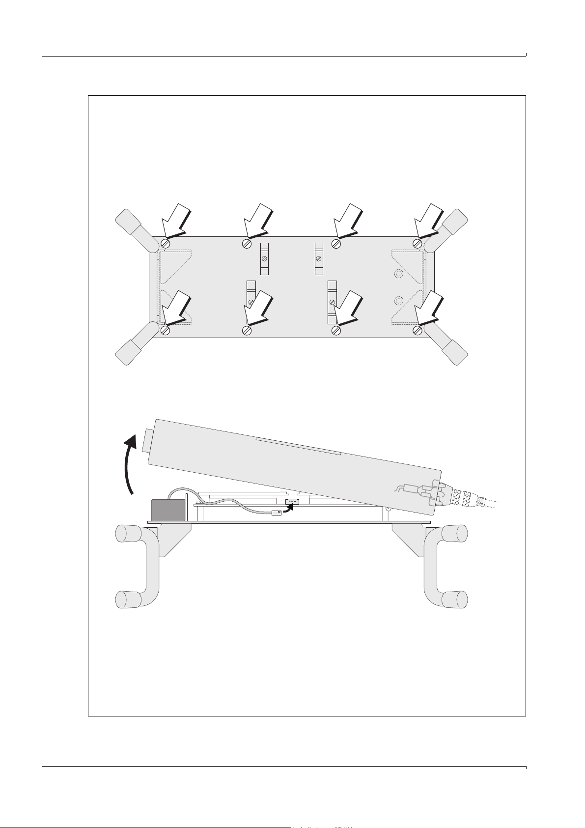
Figure 8: Changing the battery
Maintenance
28 MLA 900 Operating Instructions V2.0 8011381 © MBA Instruments GmbH
Page 29
Maintenance
5.2
Battery
Check
When the life of the built-in battery comes to an end, the message
display.
b
Whenever you open the display unit, check if
HINWEIS: Risk of damage by leaking battery
Caustic liquid could escape from the spent battery and could damage the
electronics of the display unit.
b
Remove a spent battery as soon as possible.
b
Replace the built-in battery at the latest after 3 years.
b
Note in a suitable place when the battery was last replaced.
Replacing the battery
WARNUNG: Risks in explosion-hazardous locations
b
When using the MLA 900 in hazardous locations, use only batteries of the
→
original type (
S. 30, §5.3).
BAT
is indicated.
⊗ Never open the enclosure inside a hazardous location.
1 Undo the 8 screws at the rear of the display unit.
2 Lift the upper section of the enclosure on the left-hand side.
➝ The battery is located in the lower section.
3 Detach the battery cable from the electronics (pin-and-socket connector) and remove
the battery.
4 Check the enclosure seal.
b
If the seal is damaged: replace the seal (spare parts →S. 30, §5.3).
5 Insert the new battery and connect the battery cable.
6 Screw the enclosure back together. Make sure
– that the enclosure seal is correctly positioned
– that no cables are pinched.
7 Carry out a performance test (
performance test after battery replacement outside hazardous locations.
→
S. 21, § 4.3) – Caution: for safety reasons, make this first
BAT
is indicated on the
MLA 900 Operating Instructions V 2.0 8011381 © MBA Instruments GmbH 29
Page 30
Maintenance
5.3
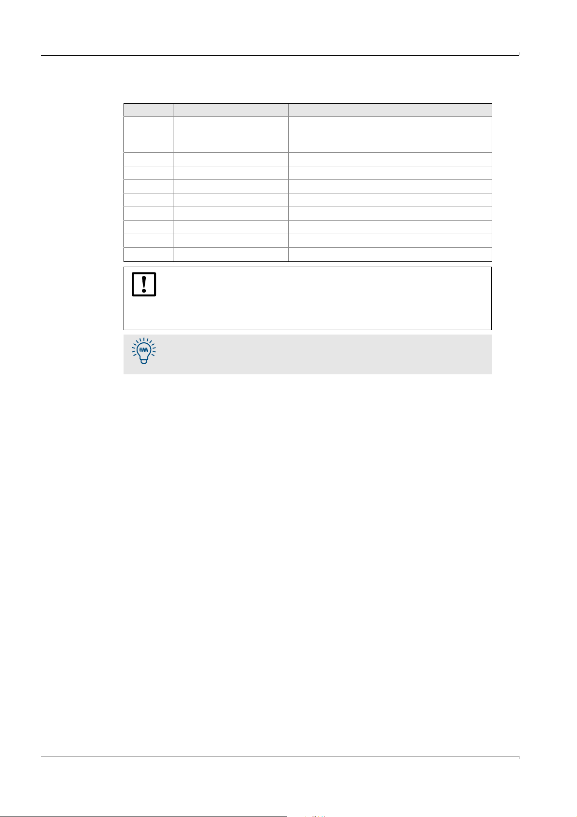
Spare parts
Part No. Description Remark
consists of: display unit, measuring probe,
1025073 MLA 900, complete
2028594 measuring probe MLA900
6026885 cable, 2 m
6026886 cable, 10 m
2028595 battery, MBA type
2028595 ground clamp
5316999 permanent magnet disc on display unit; used for performance test
4039227 seal seal for display unit enclosure
4038445 transport case
Display unit and measuring probe have been individually adapted in the
factory. If you connect a different probe, the measuring accuracy cannot be
guaranteed.
b
Only connect the measuring probe to the display unit with the identical
serial number on it.
If only the measuring probe or the display unit has become unusable or has
been lost, you can send the remaining part to the manufacturer's factory and
have this made back into a complete MLA 900.
ground clamp (with cable), 2 m cable,
10 m cable; without transport case
30 MLA 900 Operating Instructions V2.0 8011381 © MBA Instruments GmbH
Page 31

Storage, transport
MLA 900
6 Storage, transport
Storage
Shipping notes
MLA 900 Operating Instructions V 2.0 8011381 © MBA Instruments GmbH 31
Page 32
Storage, transport
6.1
Correct storage
Please observe these instructions if the MLA 900 is to be taken out of service for more than
3 months:
b
Remove the battery (→S. 29, §5.2).
b
Keep all the components stored in a dry place at room temperature (15 … 20 °C/
59 … 68 °F).
b
Observe the admissible storage and transport temperature (–20 °C … +60 °C).
WARNUNG: Damage risks caused by wrong storage
● At lower temperatures the LC displays in the display unit may freeze,
resulting in the enclosure of the LC display bursting.
● Lower temperatures affect the flexibility of the probe cables. At low
temperatures avoid bending the probe cables too far as the cable sheath
may become brittle and break.
● At higher temperatures there is a risk that caustic fluid may escape from the
battery, damaging the electronics. In addition, the LC displays may be
damaged (irreversible blackening).
6.2 Short-distance transports
b
Wind-up both the probe cable and the ground cable onto the cable brackets of the
display unit.
b
Attach the measuring probe and the ground clamp in the supports on the display unit –
do not detach the cable connections.
b
Use the hand-grip to carry the instrument.
6.3 Correct shipping
If the MLA 900 is to be transported over long distances:
b
Secure instrument: Wind the probe cable and the cable with the ground clamp carefully
onto the cable bracket of the display unit. Attach the measuring probe and the ground
clamp in the brackets of the display unit.
b
Protect the display unit: Protect the display unit against condensation, humidity and
splashing
b
Packing: Stow the MLA 900 in transport case supplied.
b
Observe the admissible storage and transport temperature (→§6.1).
b
If the instrument is to be sent for repair: observe the notes in §6.4 (→S. 33).
32 MLA 900 Operating Instructions V2.0 8011381 © MBA Instruments GmbH
Page 33

Storage, transport
6.4
Shipping for repair
b
Always send both the measuring probe and the display unit together for repair
(explanation
b
Please attach the following notes:
– A detailed, clear description of the problem (single words are fine, but merely stating
that »the instrument does not work« is of little help).
– A short description of the operating conditions.
– The name of the our representative who is informed about the problem or with whom
you have arranged transport to the workshop.
– The contact person in your company who can answer any questions that may arise.
This will help to bring your instrument quickly back to perfect operation. Please add the
information even if your matter has already been discussed with our customer service
or a representative.
→
S. 13, §3.2).
If only the measuring probe or the display unit has become unusable or
been lost, you can send the remaining part to the manufacturer's factory
and have these made back into a complete MLA 900.
MLA 900 Operating Instructions V 2.0 8011381 © MBA Instruments GmbH 33
Page 34

Storage, transport
34 MLA 900 Operating Instructions V2.0 8011381 © MBA Instruments GmbH
Page 35

Approval certificate
MLA 900
7 Approval certificate
MLA 900 Operating Instructions V 2.0 8011381 © MBA Instruments GmbH 35
Page 36
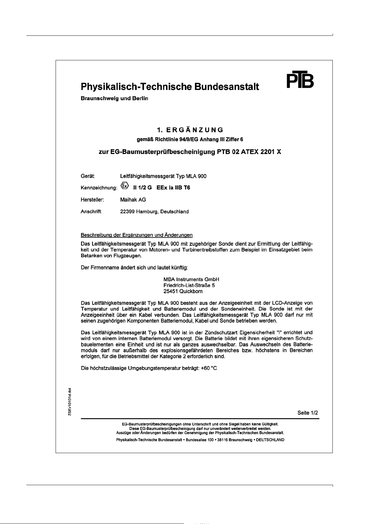
Bild 9 European approval certificate, page 1 of 2
Approval certificate
36 MLA 900 Operating Instructions V2.0 8011381 © MBA Instruments GmbH
Page 37
Approval certificate
Bild 10 Certificate of the European approval, page 2 of 2
MLA 900 Operating Instructions V 2.0 8011381 © MBA Instruments GmbH 37
Page 38

Index
Index
A
Ambient conditions during operation . . . . . . . . . . . . 8
Application restrictions
Approval
- definitions of terms
- European approval
Approved use
Area of application
Assembly
. . . . . . . . . . . . . . . . . . . . . . . . . . . . . . 8
. . . . . . . . . . . . . . . . . . . . . . . . . . . . . . . . 13
. . . . . . . . . . . . . . . . . . . . . . . 8
. . . . . . . . . . . . . . . . . . . . . . . . 9
. . . . . . . . . . . . . . . . . . . . . . . 10
. . . . . . . . . . . . . . . . . . . . . . . . . . 8
B
Battery . . . . . . . . . . . . . . . . . . . . . . . . . . . . . . . . . . 29
- replacing
- spare part
. . . . . . . . . . . . . . . . . . . . . . . . . . . . . . . 29
. . . . . . . . . . . . . . . . . . . . . . . . . . . . . . 30
C
Carrying handle . . . . . . . . . . . . . . . . . . . . . . . . . . . 17
Certificates
Checking the instrument function
Chemical Resistance
Cleaning
- the display unit
- the measuring probe
- the probe cable
Conductivity display
. . . . . . . . . . . . . . . . . . . . . . . . . . . . . . . 35
. . . . . . . . . . . . . . 21
. . . . . . . . . . . . . . . . . . . . . . . . 8
. . . . . . . . . . . . . . . . . . . . . . . . . . 27
. . . . . . . . . . . . . . . . . . . . . . 27
. . . . . . . . . . . . . . . . . . . . . . . . . . 27
. . . . . . . . . . . . . . . . . . . . . . . . 17
D
Damage (consequences) . . . . . . . . . . . . . . . . . . . . 24
Definitions of terms
Deformation of the measuring probe
DIN 51412
Display unit
- approval
- battery
- cleaning
- connecting the measuring probe
- handling
- performance test
- spare parts
- switching on/off
Displays
- fault
- limit value
. . . . . . . . . . . . . . . . . . . . . . . . . . . . . 8 - 9
. . . . . . . . . . . . . . . . . . . . . . . . . . . . . . . 10
. . . . . . . . . . . . . . . . . . . . . . . . . . . . . . . . . 29
. . . . . . . . . . . . . . . . . . . . . . . . . . . . . . . 27
. . . . . . . . . . . . . . . . . . . . . . . . . . . . . . . 17
. . . . . . . . . . . . . . . . . . . . . . . . . . . . . . . . . 17
. . . . . . . . . . . . . . . . . . . . . . . . . . . . . . . . . . . 19
. . . . . . . . . . . . . . . . . . . . . . . . . 9
. . . . . . . . . . . 24
. . . . . . . . . . . . 13
. . . . . . . . . . . . . . . . . . . . . . . . . 21
. . . . . . . . . . . . . . . . . . . . . . . . . . . . . 30
. . . . . . . . . . . . . . . . . . . . . . . . . . 17
. . . . . . . . . . . . . . . . . . . . . . . . . . . . . . 19
E
EEx ia IIB T6 . . . . . . . . . . . . . . . . . . . . . . . . . . . . . 10
EIZulBergV
ElexV
EN (European Standards)
European Standards
. . . . . . . . . . . . . . . . . . . . . . . . . . . . . . . . 9
. . . . . . . . . . . . . . . . . . . . . . . . . . . . . . . . 9 - 10
. . . . . . . . . . . . . . . . . . . . 9
. . . . . . . . . . . . . . . . . . . . . . . . 9
F
Fault (consequences) . . . . . . . . . . . . . . . . . . . . . . .24
Fault displays
. . . . . . . . . . . . . . . . . . . . . . . . . . . . .19
G
Ground terminal
- handling during measurement
- spare part
- testing
. . . . . . . . . . . . . . . . . . . . . . . . . . . . . . . 30
. . . . . . . . . . . . . . . . . . . . . . . . . . . . . . . . . . 13
. . . . . . . . . . . . . . . 23
H
Handling . . . . . . . . . . . . . . . . . . . . . . . . . . . . . . . . .15
Hazardous areas
. . . . . . . . . . . . . . . . . . . . . . . . . . . 9
I
Information symbols . . . . . . . . . . . . . . . . . . . . . . . . 2
Intrinsically safety
. . . . . . . . . . . . . . . . . . . . . . . . . . 9
L
Limit value . . . . . . . . . . . . . . . . . . . . . . . . . . . . . . . .19
M
Maintenance . . . . . . . . . . . . . . . . . . . . . . . . . . . . . .25
Materials (chemical resistance)
Measuring probe
- approval
- chemical resistance
- cleaning
- connecting the display unit
- handling during measurement
- measures in case of deformation/damage
- performance test
- spare part
Measuring procedure
Measuring value displays
Mining ordinance
. . . . . . . . . . . . . . . . . . . . . . . . . . . . . . . .10
. . . . . . . . . . . . . . . . . . . . . . . 8
. . . . . . . . . . . . . . . . . . . . . . . . . . . . . . . .27
. . . . . . . . . . . . . . . . . . . . . . . . .21
. . . . . . . . . . . . . . . . . . . . . . . . . . . . . . . 30
. . . . . . . . . . . . . . . . . . . . . . .23
. . . . . . . . . . . . . . . . . . . . . . . . . . . 9
. . . . . . . . . . . . . . . . 8
. . . . . . . . . . . . . . . . . .13
. . . . . . . . . . . . . . . 23
. . . . . . 24
. . . . . . . . . . . . . . . . . . . . 17
O
Official approval . . . . . . . . . . . . . . . . . . . . . . . . . . . . 9
Operating conditions
. . . . . . . . . . . . . . . . . . . . . . . .10
P
Performance test . . . . . . . . . . . . . . . . . . . . . . . . . . . 21
Preparing for operation
Probe cable
- cleaning
- connection
- maximum length
. . . . . . . . . . . . . . . . . . . . . . . . . . . . . . . .27
. . . . . . . . . . . . . . . . . . . . . . . . . . . . . .13
. . . . . . . . . . . . . . . . . . . . . . 11
. . . . . . . . . . . . . . . . . . . . . . . . . .13
38 MLA 900 Operating Instructions V2.0 8011381 © MBA Instruments GmbH
Page 39

Index
R
Regulations . . . . . . . . . . . . . . . . . . . . . . . . . . . . . . . 9
S
Seal for display unit . . . . . . . . . . . . . . . . . . . . . . . . 30
Shipping
Signal words
Spare parts
Storage
Supply schedule
Switching on/off
Symbols (explanation)
. . . . . . . . . . . . . . . . . . . . . . . . . . . . . . . . . 32
. . . . . . . . . . . . . . . . . . . . . . . . . . . . . . 2
. . . . . . . . . . . . . . . . . . . . . . . . . . . . . . 30
. . . . . . . . . . . . . . . . . . . . . . . . . . . . . . 31 - 32
. . . . . . . . . . . . . . . . . . . . . . . . . . 12
. . . . . . . . . . . . . . . . . . . . . . . . . . . 17
. . . . . . . . . . . . . . . . . . . . . . . 2
T
Temperature
-display
- during operation
- for storage/transport
Transport
. . . . . . . . . . . . . . . . . . . . . . . . . . . . . . . . . 17
. . . . . . . . . . . . . . . . . . . . . . . . . . . 8
. . . . . . . . . . . . . . . . . . . . . . 32
. . . . . . . . . . . . . . . . . . . . . . . . . . . . . 31 - 32
W
Warning symbols, warning levels . . . . . . . . . . . . . . . 2
Z
Zone 0, Zone 1 . . . . . . . . . . . . . . . . . . . . . . . . . . . . . 9
MLA 900 Operating Instructions V 2.0 8011381 © MBA Instruments GmbH 39
Page 40

MLA 900
MBA Instruments GmbH
Friedrich-List-Str. 7
Telefon +49 (0) 41 06 123 888-0
www.mba-instruments.de · [email protected]
· D-25451 Quickborn · Germany
· Fax +49 (0) 41 06 123 888-9
8011381 (2.0) · 2010-06
 Loading...