

Page 1

Table of Contents
Introduction 4
Instrument Cluster 12
Warning lights and chimes 12
Gauges 17
Entertainment Systems 19
Auxiliary input jack 25
Climate Controls 29
Manual heating and air conditioning 29
Rear window defroster 31
Lights 32
Headlamps 32
Turn signal control 35
Bulb replacement 36
Driver Controls 42
Windshield wiper/washer control 42
Steering wheel adjustment 43
Power windows 47
Mirrors 48
Cruise control 49
Moon roof 53
Locks and Security 60
Keys 60
Locks 62
Anti-theft system 68
Seating and Safety Restraints 72
Seating 72
Safety restraints 81
Airbags 97
Child restraints 113
2008 Tribute (j14)
Owners Guide (post-2002-fmt)
USA (fus)
1
Page 2

Table of Contents
Tires, Wheels and Loading 125
Tire information 127
Tire inflation 130
Tire Pressure Monitoring System (TPMS) 143
Vehicle loading 148
Trailer towing 154
Recreational towing 160
Driving 161
Starting 161
Brakes 166
Electronic stability control 168
Transmission operation 173
Roadside Emergencies 188
Hazard flasher switch 188
Fuel pump shut-off switch 189
Fuses and relays 189
Changing tires 196
Lug nut torque 206
Overheating 206
Jump starting 207
Wrecker towing 213
Customer Assistance 215
Reporting safety defects (U.S. only) 225
Reporting safety defects (Canada only) 225
Cleaning 226
2
2008 Tribute (j14)
Owners Guide (post-2002-fmt)
USA (fus)
Page 3

Table of Contents
Maintenance and Specifications 232
Engine compartment 240
Engine oil 244
Battery 248
Engine coolant 250
Fuel information 256
Air filter(s) 269
Maintenance product specifications and capacities 271
Engine data 273
Accessories 276
Index 277
All rights reserved. Reproduction by any means, electronic or mechanical
including photocopying, recording or by any information storage and retrieval
system or translation in whole or part is not permitted without written
authorization from MNAO. MNAO may change the contents without notice and
without incurring obligation.
Copyright © 2006 MNAO
2008 Tribute (j14)
Owners Guide (post-2002-fmt)
USA (fus)
3
Page 4

Introduction
CALIFORNIA Proposition 65 Warning
WARNING: Engine exhaust, some of its constituents, and
certain vehicle components contain or emit chemicals known to
the State of California to cause cancer and birth defects or
other reproductive harm. In addition, certain fluids contained in
vehicles and certain products of component wear contain or
emit chemicals known to the State of California to cause cancer
and birth defects or other reproductive harm.
PERCHLORATE MATERIAL
Certain components of this vehicle such as air bag modules, seat belt
pretensioners, and button cell batteries may contain Perchlorate Material
– Special handling may apply for service or vehicle end of life disposal.
See www.dtsc.ca.gov/hazardouswaste/perchlorate.
CONGRATULATIONS
Congratulations on acquiring your new Mazda product. Please take the
time to get well acquainted with your vehicle by reading this handbook.
The more you know and understand about your vehicle, the greater the
safety and pleasure you will derive from driving it.
For more information on Mazda and its products visit the following
website:
• In the United States: www.mazdausa.com
• In Canada: www.mazda.ca
Additional owner information is given in separate publications or refer to
the Mazda importers/distributors section in the Customer Assistance
chapter.
This Owner’s Manual describes every option and model variant available
and therefore some of the items covered may not apply to your
particular vehicle. Furthermore, due to printing cycles it may describe
options before they are generally available.
Remember to pass on the Owner’s Manual when reselling the vehicle. It
is an integral part of the vehicle.
4
2008 Tribute (j14)
Owners Guide (post-2002-fmt)
USA (fus)
Page 5
Introduction
WARNING: In the event of an accident the Fuel pump shut-off
switch will automatically cut off the fuel supply to the engine.
The switch can also be activated through sudden vibration (e.g.
collision when parking). To reset the switch, refer to the Fuel
pump shut-off switch in the Roadside Emergencies chapter.
SAFETY AND ENVIRONMENT PROTECTION
Warning symbols in this guide
How can you reduce the risk of
personal injury to yourself or
others? In this guide, answers to
such questions are contained in
comments highlighted by a bold
WARNING statement. These comments should be read and observed.
Warning symbols on your vehicle
When you see this symbol, it is
imperative that you consult the
relevant section of this guide before
touching or attempting adjustment
of any kind.
Protecting the environment
We must all play our part in
protecting the environment. Correct
vehicle usage and the authorized
disposal of waste, cleaning and
lubrication materials are significant
steps towards this aim. Information in this respect is highlighted in this
guide with the tree symbol.
Always dispose of used automotive fluids in a responsible manner. Follow
your community’s regulations and standards for recycling and disposing
of automotive fluids.
2008 Tribute (j14)
Owners Guide (post-2002-fmt)
USA (fus)
5
Page 6

Introduction
BREAKING-IN YOUR VEHICLE
There are no particular breaking-in rules for your vehicle. During the
first 1,000 miles (1,600 km) of driving, vary speeds frequently. This is
necessary to give the moving parts a chance to break in.
SPECIAL NOTICES
Event Data Recorder
The computer in your vehicle is capable of recording detailed data
potentially including but not limited to information such as:
• the use of restraint systems including seat belts by the driver and
passengers,
• information about the performance of various systems and modules in
the vehicle, and
• information related to engine, throttle, steering, brake or other system
status potentially including information related to how the driver
operates the vehicle including but not limited to vehicle speed.
This information may be stored during regular operation or in a crash or
near crash event. This stored information may be read out and used by:
• service and repair facilities.
• law enforcement or government agencies.
• the Manufacturer and Distributor.
6
2008 Tribute (j14)
Owners Guide (post-2002-fmt)
USA (fus)
Page 7

Introduction
Emission warranty
The New Vehicle Limited Warranty includes Bumper to Bumper
Coverage, Safety Restraint Coverage and Corrosion Coverage. In addition,
your vehicle is eligible for Emissions Defect and Emissions Performance
Warranties. For a detailed description of what is covered and what is not
covered, refer to the Warranty Information Booklet that is provided to
you along with your Owner’s Manual.
Using your vehicle with a snowplow
WARNING: Do not use this vehicle for snowplowing.
Your vehicle is not equipped with a snowplowing package.
Using your vehicle as an ambulance
WARNING: Do not use this vehicle as an ambulance.
Your vehicle is not equipped with an ambulance preparation package.
2008 Tribute (j14)
Owners Guide (post-2002-fmt)
USA (fus)
7
Page 8
Introduction
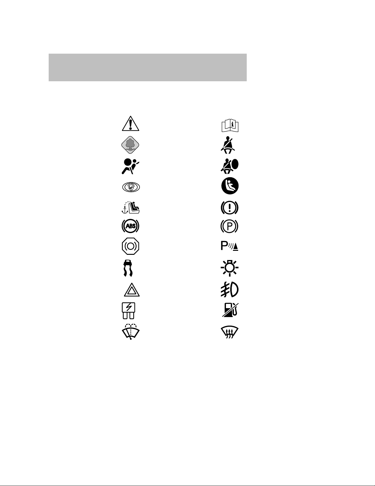
These are some of the symbols you may see on your vehicle.
Vehicle Symbol Glossary
Safety Alert
Protecting the
Environment
Airbag - Front Airbag - Side
Passenger Airbag Off
Child Seat Tether
Anchor
Anti-Lock Brake System Parking Brake System
Brake Fluid Non-Petroleum Based
Stability Control System Master Lighting Switch
Hazard Warning Flasher Fog Lamps-Front
See Owner’s Manual
Fasten Seat Belt
Child Seat Lower
Anchor
Brake System
Parking Aid System
Fuse Compartment Fuel Pump Reset
Windshield Wash/Wipe
8
Windshield
Defrost/Demist
2008 Tribute (j14)
Owners Guide (post-2002-fmt)
USA (fus)
Page 9
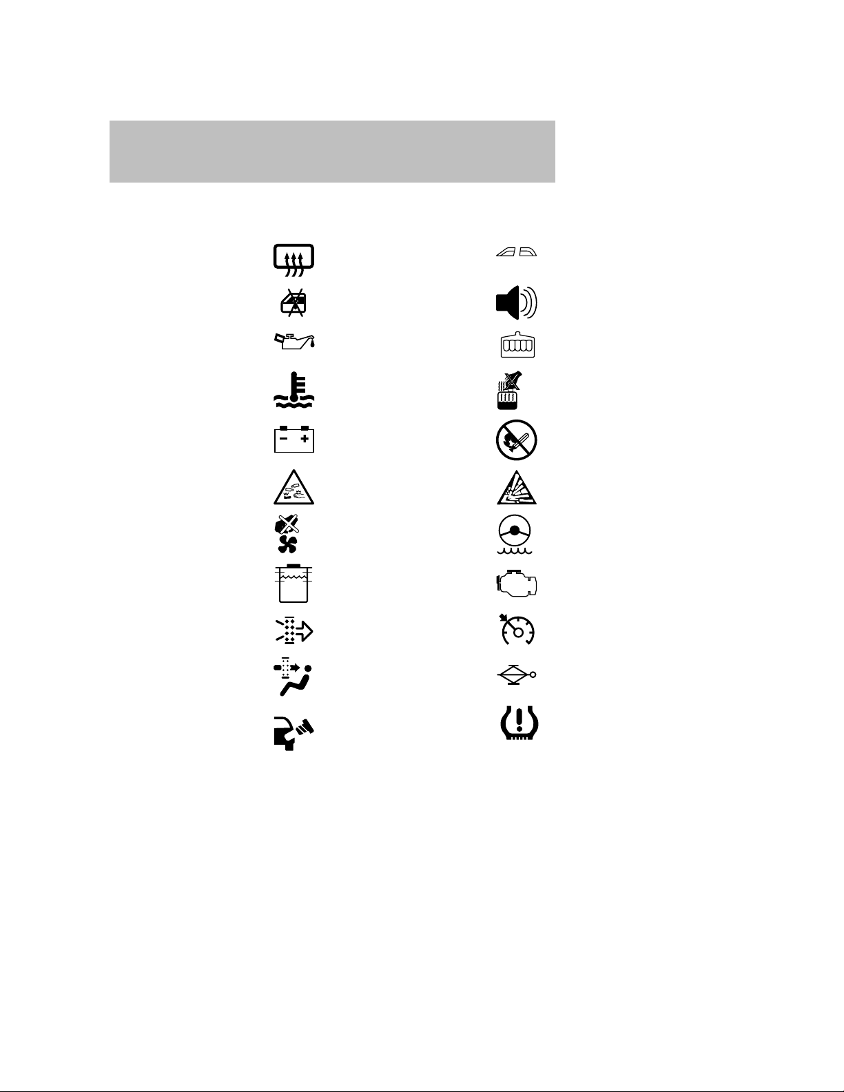
Vehicle Symbol Glossary
Introduction
Rear Window
Defrost/Demist
Power Window Lockout
Power Windows
Personal Alarm System
Feature
Engine Oil Engine Coolant
Engine Coolant
Temperature
Battery
Do Not Open When Hot
Avoid Smoking, Flames,
or Sparks
Battery Acid Explosive Gas
Fan Warning Power Steering Fluid
Maintain Correct Fluid
Level
MAX
MIN
Emission System
Engine Air Filter Speed Control
Passenger Compartment
Air Filter
Check Fuel Cap
Jack
Low Tire Pressure
Warning
INFORMATION ABOUT THIS GUIDE
The information found in this guide was accurate at the time of printing.
Mazda may change the contents without notice.
2008 Tribute (j14)
Owners Guide (post-2002-fmt)
USA (fus)
9
Page 10
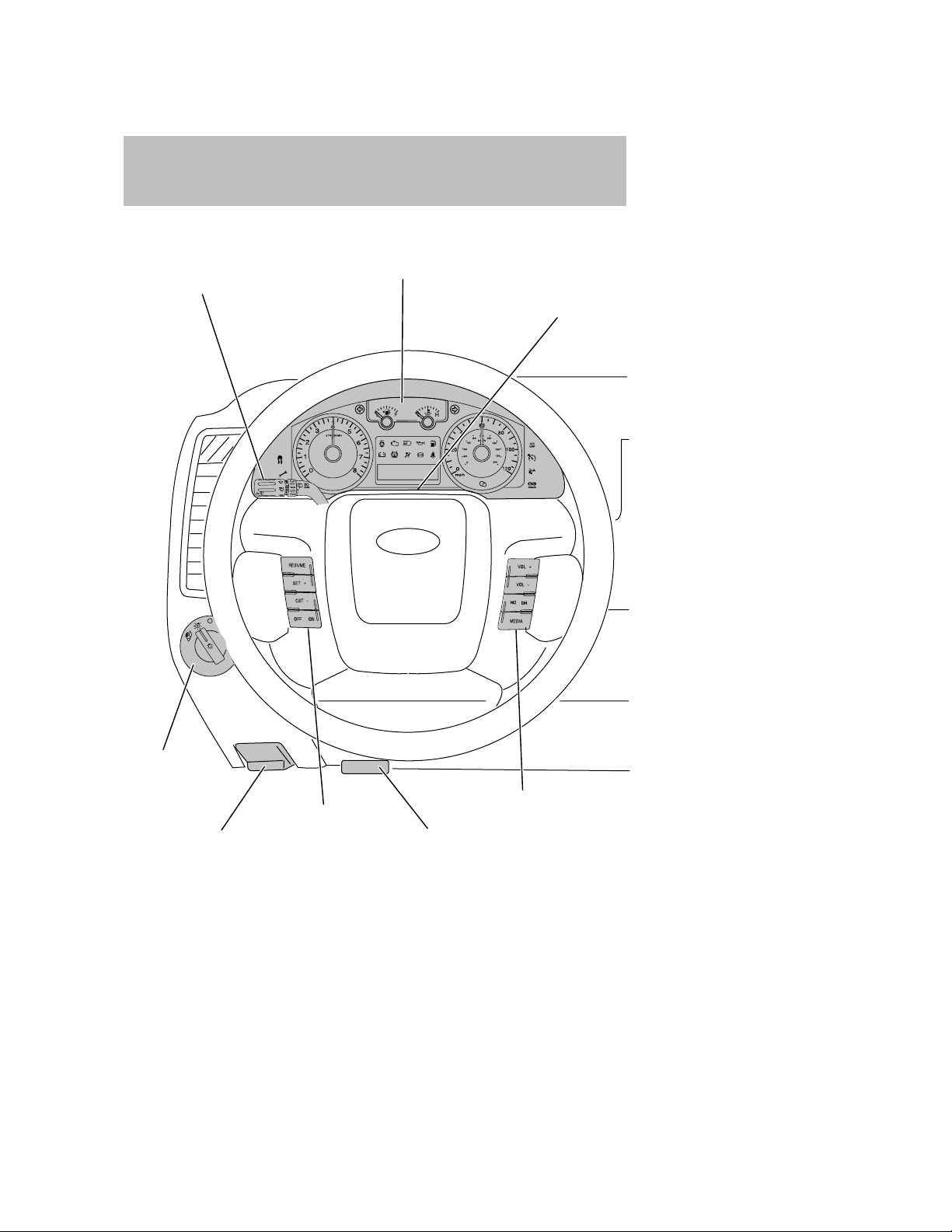
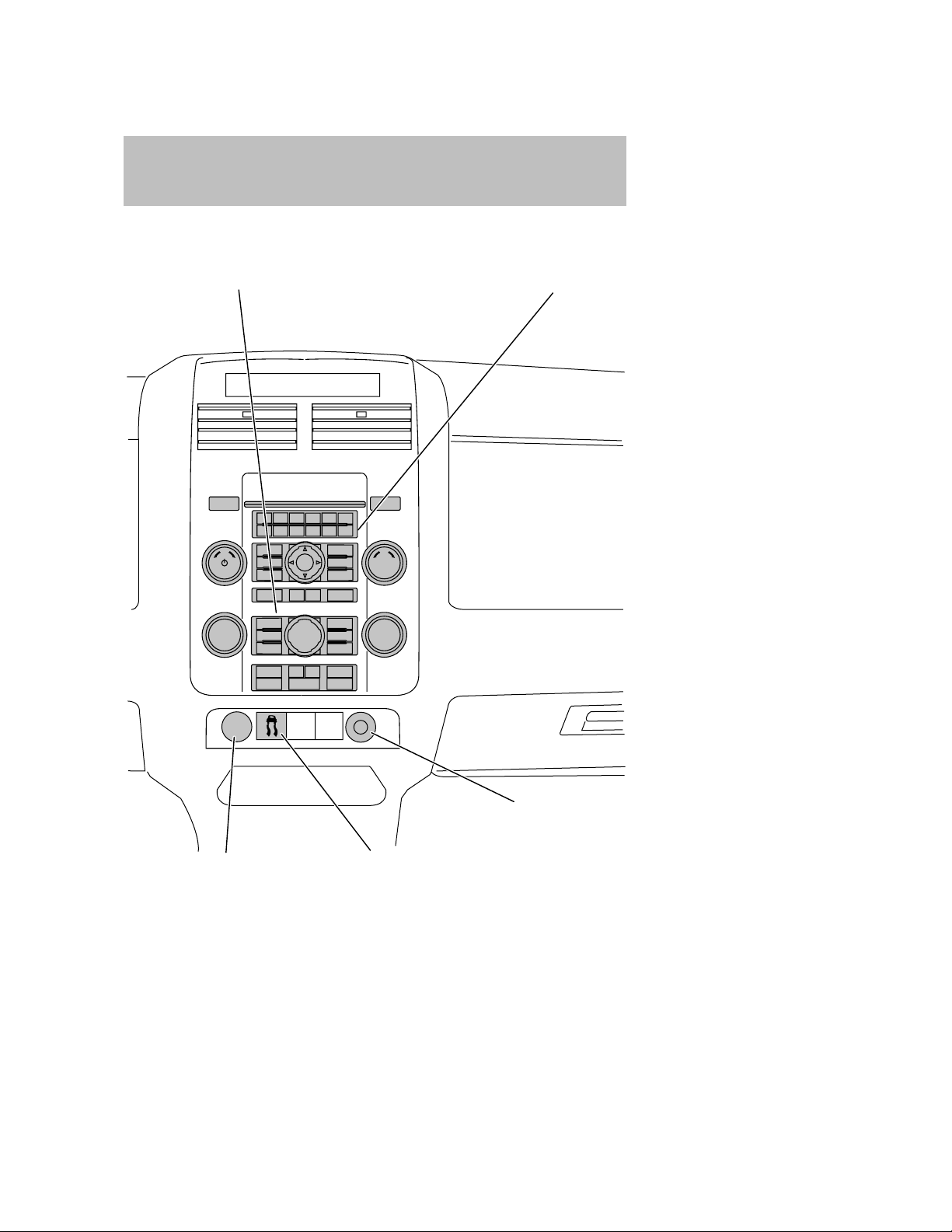
Instrument Cluster
Multi-function lever
(pg. 42)
Instrument cluster
(pg. 12)
Hazard flasher control
(pg. 188)
Headlamp
control
(pg. 32)
Speed controls*
(pg. 49)
Parking brake release
(pg. 167)
* if equipped
10
2008 Tribute (j14)
Owners Guide (post-2002-fmt)
USA (fus)
Steering wheel controls*
(pg. 52)
Hood release
(pg. 239)
Page 11
Instrument Cluster
Climate controls
(pg. 29)
Audio system
(pg. 19)
Auxiliary power point
(pg. 46)
Electronic stability
control
(pg. 168)
2008 Tribute (j14)
Owners Guide (post-2002-fmt)
USA (fus)
Auxiliary input jack
(pg. 25)
*if equipped
11
Page 12
Instrument Cluster
WARNING LIGHTS AND CHIMES
Warning lights and gauges can alert you to a vehicle condition that may
become serious enough to cause extensive repairs. A warning light may
illuminate when a problem exists with one of your vehicle’s functions.
Many lights will illuminate when you start your vehicle to make sure the
bulbs work. If any light remains on after starting the vehicle, refer to the
respective system warning light for additional information.
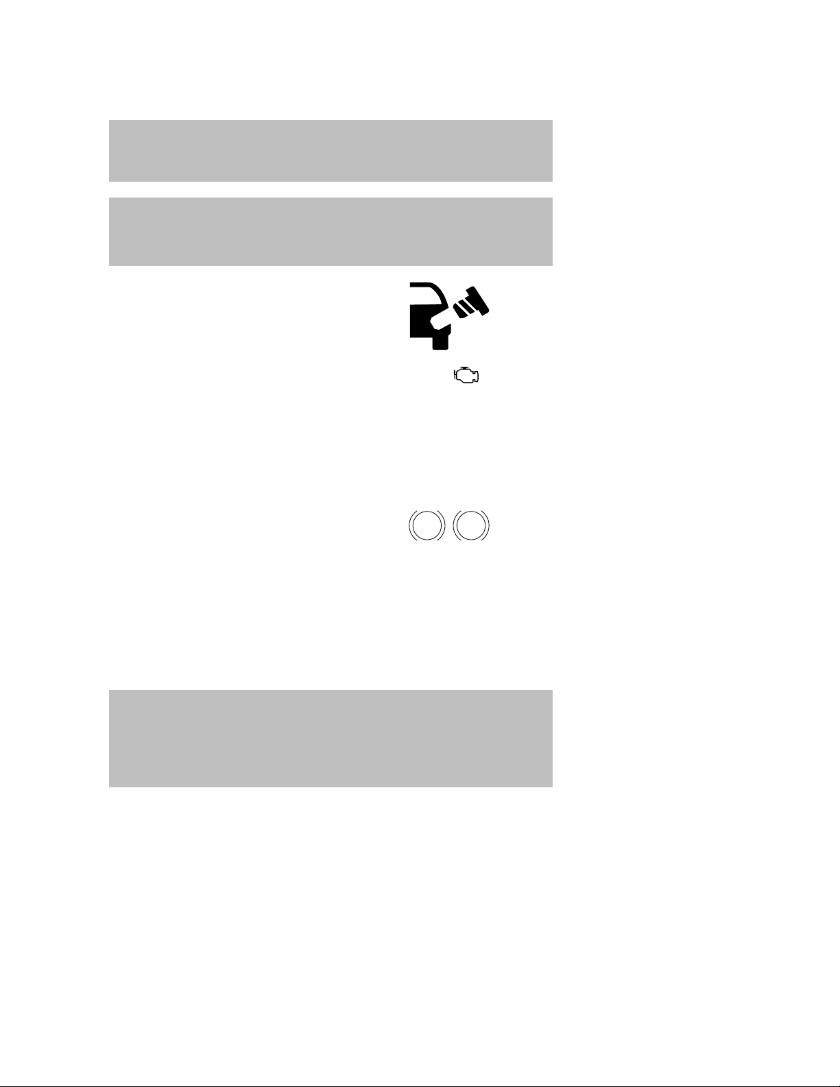
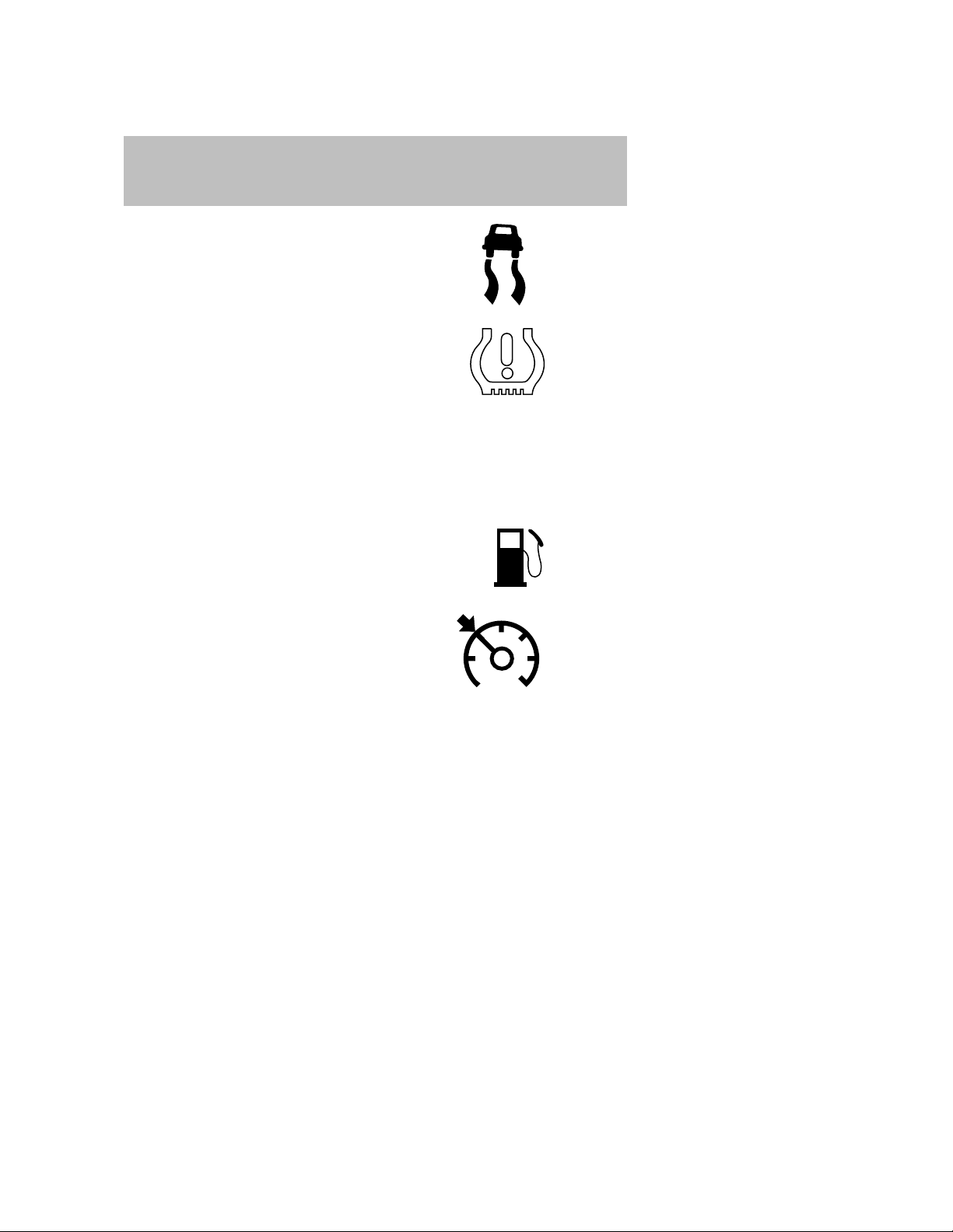
Check engine: The Check Engine
indicator light illuminates when the
ignition is first turned to the RUN
position to check the bulb and to
indicate whether the vehicle is ready for Inspection/Maintenance (I/M)
testing. Normally, the ⬙Check Engine⬙ light will stay on until the engine is
cranked, then turn itself off if no malfunctions are present. However, if
after 15 seconds the ⬙Check Engine⬙ light blinks eight times, it means
that the vehicle is not ready for I/M testing. See the Readiness for
Inspection/Maintenance (I/M) testing in the Maintenance and
Specifications chapter.
Solid illumination after the engine is started indicates the On Board
Diagnostics System (OBD-II) has detected a malfunction. Refer to On
board diagnostics (OBD-II) in the Maintenance and Specifications
chapter. If the light is blinking, engine misfire is occurring which could
damage your catalytic converter. Drive in a moderate fashion (avoid
heavy acceleration and deceleration) and have your vehicle serviced
immediately by your authorized dealer.
If the
available opportunity.
light remains on, have your vehicle serviced at the first
12
2008 Tribute (j14)
Owners Guide (post-2002-fmt)
USA (fus)
Page 13
Instrument Cluster
WARNING: Under engine misfire conditions, excessive exhaust
temperatures could damage the catalytic converter, the fuel
system, interior floor coverings or other vehicle components,
possibly causing a fire.
Check fuel cap: Momentarily
illuminates when the ignition is
turned to the RUN position to
ensure your bulb is working. When
the light stays on, check the fuel
filler cap. Continuing to operate the
vehicle with the check fuel cap light on, can activate the
light. When the fuel filler cap is properly re-installed, the light(s) will
turn off after a period of normal driving. This period will vary depending
on driving conditions.
It may take a long period of time for the system to detect an
improperly installed fuel filler cap.
For more information, refer to Fuel filler cap in the Maintenance and
Specifications chapter.
Brake system warning light: To
confirm the brake system warning
light is functional, it will
momentarily illuminate when the
ignition is turned to the RUN
position when the engine is not running, or in a position between RUN
and START, or by applying the parking brake when the ignition is turned
to the RUN position. If the brake system warning light does not
illuminate at this time, seek service immediately from an authorized
Mazda dealer. Illumination after releasing the parking brake indicates low
brake fluid level and the brake system should be inspected immediately
by an authorized Mazda dealer.
BRAKE
warning
P!
WARNING: Driving a vehicle with the brake system warning
light on is dangerous. A significant decrease in braking
performance may occur. It will take you longer to stop the
vehicle. Have the vehicle checked by your authorized dealer.
Driving extended distances with the parking brake engaged can
cause brake failure and the risk of personal injury.
2008 Tribute (j14)
Owners Guide (post-2002-fmt)
USA (fus)
13
Page 14
Instrument Cluster
Anti-lock brake system (ABS): If
the ABS light stays illuminated or
continues to flash, a malfunction has
been detected, have the system
serviced immediately by an
authorized Mazda dealer. Normal braking is still functional unless the
brake system warning light also is illuminated.
WARNING: If the light remains on, continues to flash or fails
to illuminate, have the system serviced immediately by an
authorized Mazda dealer. With the ABS light on, the anti-lock
brake system is disabled but normal braking is still effective
unless the brake warning light also remains illuminated with
the parking brake released.
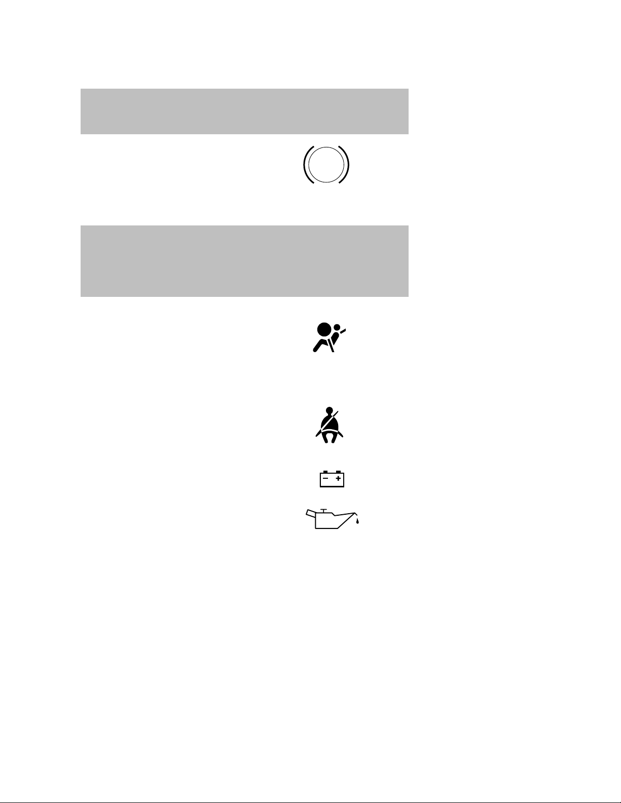
Airbag readiness: If this light fails
to illuminate when ignition is turned
to RUN, continues to flash or
remains on, have the system
serviced immediately by an authorized Mazda dealer. A chime will also
sound when a malfunction in the supplemental restraint system has been
detected.
Seat belt: Reminds you to fasten
your seat belt. A Belt-Minder威
chime will also sound to remind you
to fasten your seat belt. Refer to the
Seating and safety restraints
chapter to activate/deactivate the Belt-Minder威 chime feature.
Charging system: Illuminates when
the battery is not charging properly.
ABS
Engine oil pressure: Illuminates
when the oil pressure falls below the
normal range, refer to Engine oil in
the Maintenance and
Specifications chapter.
14
2008 Tribute (j14)
Owners Guide (post-2002-fmt)
USA (fus)
Page 15
Instrument Cluster
Traction Control娂: Illuminates
when the Traction Control娂 is
active. If the light remains on, have
the system serviced immediately,
refer to the Driving chapter for
more information.
Low tire pressure warning:
Illuminates when your tire pressure
is low. If the light remains ON at
start up or while driving, the tire
pressure should be checked. Refer
to Inspecting and Inflating Your Tires in the Tires, Wheels and
Loading chapter. When the ignition is first turned to RUN, the light will
illuminate for 3 seconds to ensure the bulb is working. If the light does
not turn ON or begins to flash, have the system inspected by your
authorized dealer. For more information on this system, refer to
Understanding Your Tire Pressure Monitoring System in the Tires,
Wheels and Loading chapter.
Low fuel: Illuminates when the fuel
level in the fuel tank is at or near
empty (refer to Fuel gauge in this
chapter).
Cruise control/Speed control:
Illuminates when the cruise
control/speed control is activated.
Turns off when the cruise
control/speed control system is
deactivated, refer to the Driver
Controls chapter.
Overdrive off (automatic
transmission): Illuminates when
the overdrive function of the
transmission has been turned off.
Refer to the Driving chapter for transmission function and operation.If
the light flashes steadily, have the system serviced immediately,
or damage to the transmission could occur.
O/D
OFF
2008 Tribute (j14)
Owners Guide (post-2002-fmt)
USA (fus)
15
Page 16
Instrument Cluster
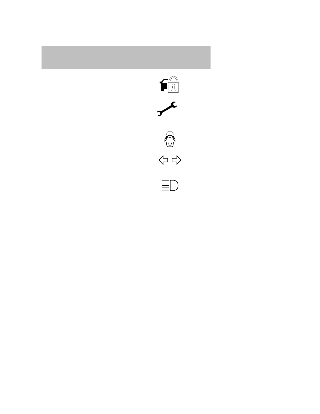
Anti-theft system: Flashes when
the SecuriLock娂 Passive Anti-theft
System has been activated.
Throttle control/Powertrain:
Illuminates when a powertrain fault
has been detected. Contact your
authorized dealer as soon as
possible.
Door ajar: Illuminates when the
ignition is in the RUN position and
any door is open.
Turn signal: Illuminates when the
left or right turn signal or the
hazard lights are turned on. If the
indicators flash faster, check for a burned out bulb.
High beams: Illuminates when the
high beam headlamps are turned on.
Key-in-ignition warning chime: Sounds when the key is left in the
ignition in the OFF/LOCK or ACCESSORY position and the driver’s door
is opened.
Headlamps on warning chime: Sounds when the headlamps or parking
lamps are on, the ignition is off (the key is not in the ignition) and the
driver’s door is opened.
Parking brake ON chime: Sounds when the parking brake is left ON
and the vehicle is driven. If the warning stays on after the park brake is
off, contact your authorized dealer as soon as possible.
16
2008 Tribute (j14)
Owners Guide (post-2002-fmt)
USA (fus)
Page 17
Instrument Cluster
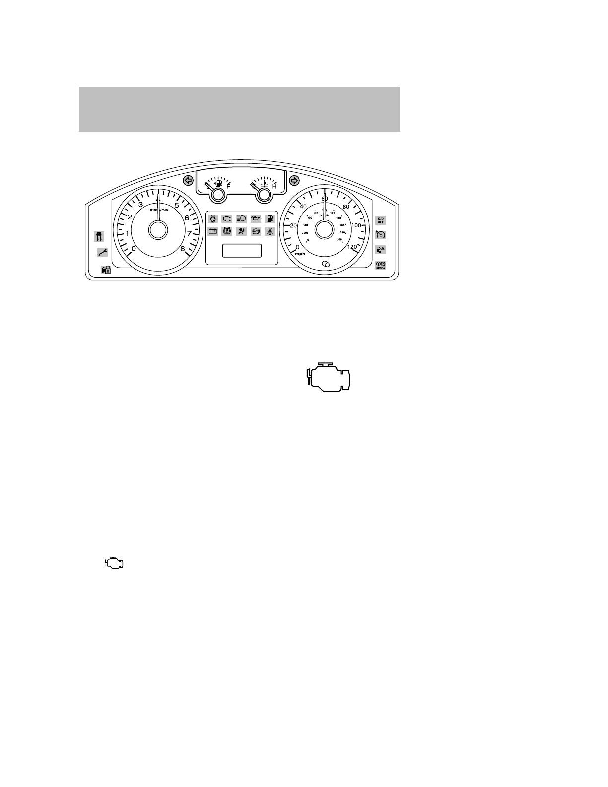
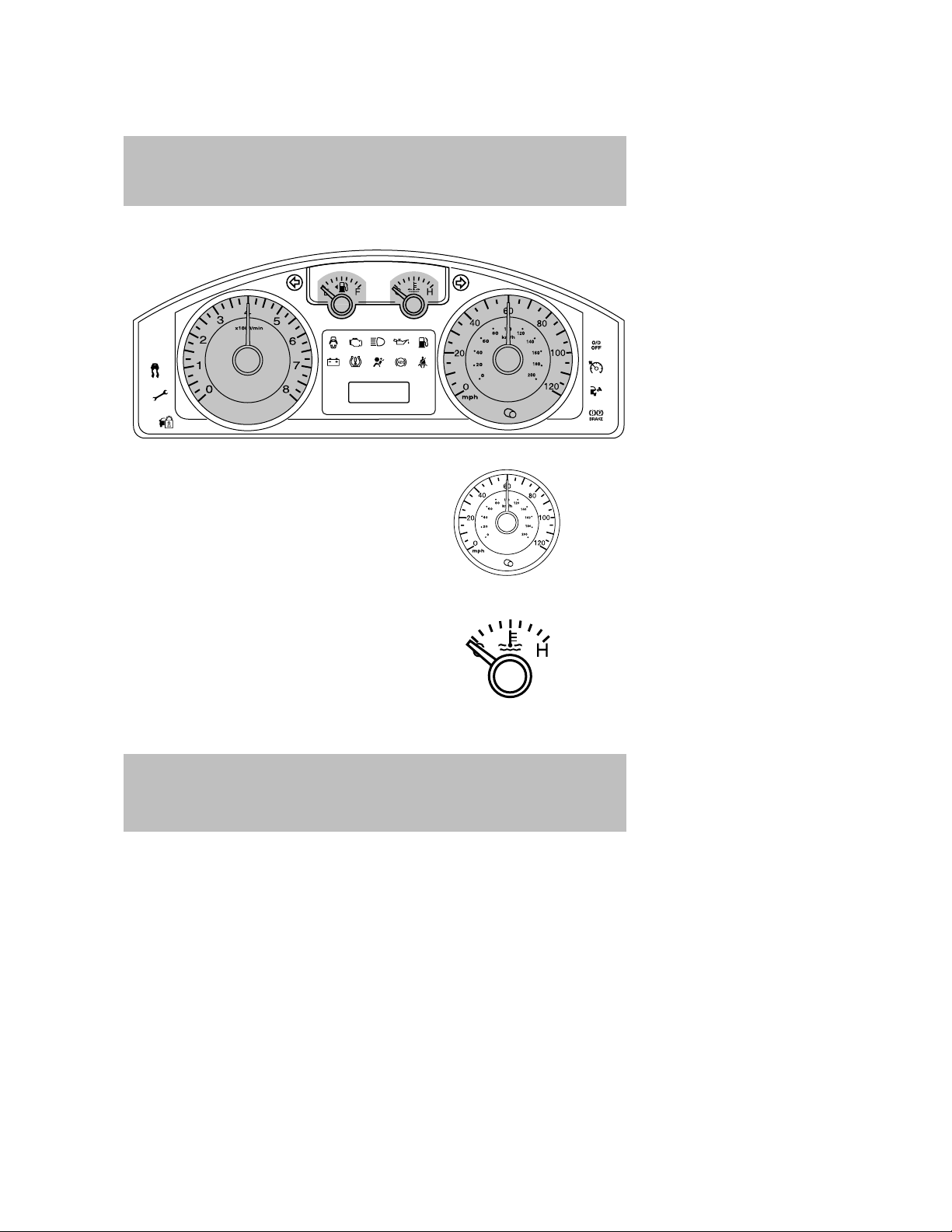
GAUGES
Speedometer: Indicates the
current vehicle speed.
Engine coolant temperature
gauge: Indicates engine coolant
temperature. At normal operating
temperature, the needle will be in
the normal range (between “H” and
“C”). If it enters the red section,
the engine is overheating. Stop
the vehicle as soon as safely
possible, switch off the engine and let the engine cool.
WARNING: When the engine and radiator are hot, scalding
coolant and steam may shoot out under pressure and cause
serious injury. Do not remove the cooling system cap when the
engine and radiator are hot.
2008 Tribute (j14)
Owners Guide (post-2002-fmt)
USA (fus)
17
Page 18
Instrument Cluster
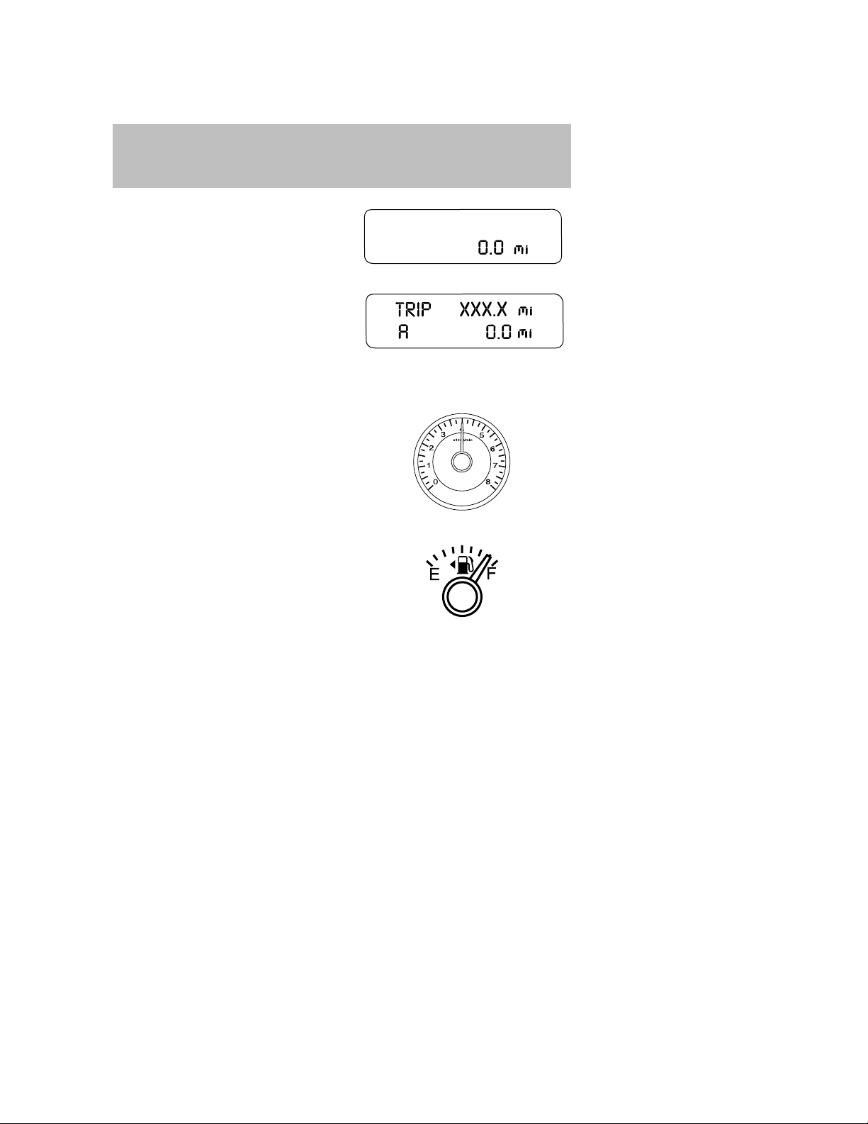
Odometer: Registers the total miles
(kilometers) of the vehicle.
Trip odometer: Registers the miles
(kilometers) of individual journeys.
To reset, tap on the trip
SELECT/RESET button to toggle
the display between the TRIP A and
TRIP B. Holding the
SELECT/RESET button for two seconds will reset the trip odometer to
zero.
Tachometer: Indicates the engine
speed in revolutions per minute.
Driving with your tachometer
pointer continuously at the top of
the scale may damage the engine.
Fuel gauge: Indicates
approximately how much fuel is left
in the fuel tank (when the ignition
is in the ON position). The fuel
gauge may vary slightly when the
vehicle is in motion or on a grade.
The arrow near the fuel pump icon
indicates which side of the vehicle
the fuel filler door is located.
Refer to Filling the tank in the Maintenance and Specifications
chapter for more information.
18
2008 Tribute (j14)
Owners Guide (post-2002-fmt)
USA (fus)
Page 19
Entertainment Systems
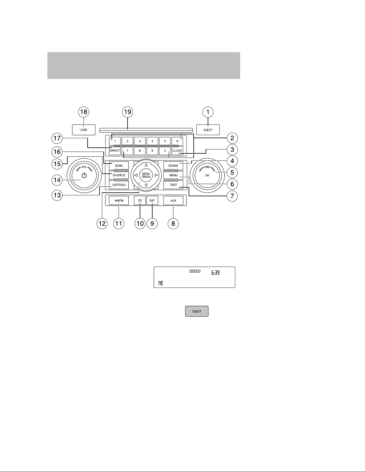
AUDIO SYSTEMS
AM/FM/single CD/in-dash CD6/MP3 sound system
Accessory delay: Your vehicle is equipped with accessory delay. With
this feature, the window switches, radio and moon roof (if equipped)
may be used for up to ten minutes after the ignition is turned off or until
either front door is opened.
Note: Your vehicle is equipped with
a unique audio system. If your
display shows six small circles in the
display, your audio system is a CD6
system. If not, your system is a
Single CD system.
1. EJECT: For a single CD
system, press EJECT to eject
the CD.
For a CD6 system, press EJECT and select the desired CD slot by
pressing the corresponding memory preset #. The display will read
EJECTING #. When the system has ejected the CD, the display will
read REMOVE CD #. Remove the CD. If you do not remove the CD
2008 Tribute (j14)
Owners Guide (post-2002-fmt)
USA (fus)
19
Page 20
Entertainment Systems
the system will reload the disc.
To auto eject all loaded discs, press and hold EJECT. The system
will eject all discs and prompt you when to remove them.
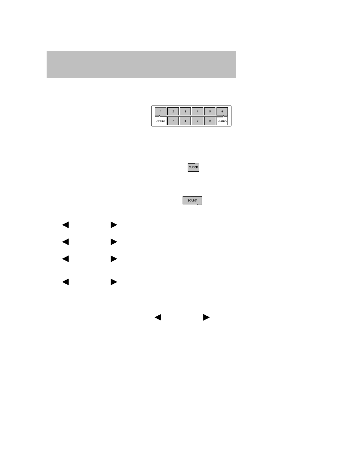
2. MEMORY PRESETS:In radio
mode, to set a station, select
the desired frequency band, AM,
FM1 or FM2. Tune to the
desired station. Press and hold a
preset button until sound returns and PRESET # SAVED appears in
the display. You can save up to 30 stations, 10 in AM, 10 in FM1 and
FM2.
In CD/MP3 mode, press to select tracks or desired folders.
3. CLOCK: To set the time, press
CLOCK. The display will read
SET TIME. Use the memory
preset #s to enter in the desired time, hours and minutes. The clock
will then begin from that time.
4. SOUND: Press repeatedly to
cycle through the following
features:
BASS: Press SOUND repeatedly to reach the bass setting.
Press
TREBLE: Press SOUND repeatedly to reach the treble setting.
Press
BALANCE: Press SOUND repeatedly to reach the balance setting.
Press
right (R) speakers.
FADE: Press SOUND repeatedly to reach the bass setting.
Press
and front (F) speakers.
SPEED COMPENSATED VOLUME (if equipped): Press SOUND
repeatedly to reach the SPEED COMPENSATED VOLUME setting. Radio
volume automatically gets louder with increasing vehicle speed to
compensate for road and wind noise. Use
adjust.
The default setting is off; increasing your vehicle speed will not change
the volume level.
SEEK/TRACK to adjust the level of bass.
SEEK/TRACK to adjust the level of treble.
SEEK/TRACK to adjust the audio between the left (L) and
SEEK/TRACK to adjust the audio between the back (B)
SEEK/TRACK to
20
2008 Tribute (j14)
Owners Guide (post-2002-fmt)
USA (fus)
Page 21
Entertainment Systems
Adjust 1–7: Increasing this setting from 1 (lowest setting) to 7 (highest
setting) allows the radio volume to automatically change slightly with
vehicle speed to compensate for road and wind noise.
Recommended level is 1–3; SPEED OFF turns the feature off and level 7
is the maximum setting.
ALL SEATS (Occupancy mode, if equipped): Press SOUND
repeatedly to reach the Occupancy mode setting.
Press
SEATS, DRIVERS SEAT or REAR SEATS.
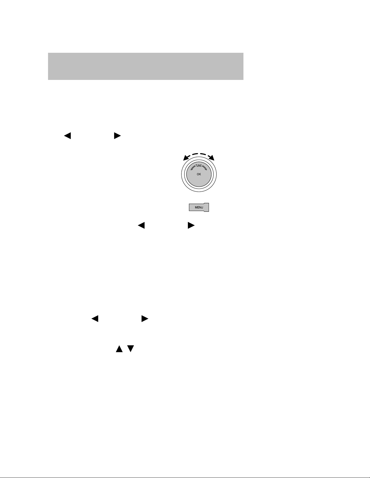
5. TUNE: In radio mode, turn
6. MENU: Press repeatedly to
SEEK/TRACK to select and optimize sound for ALL
right / left to go up /down the
frequency band in individual
increments.
access the following features:
AUTO PRESET ON/OFF: Press
between ON/OFF. Autoset allows you to set the strongest local radio
stations without losing your original manually set preset stations for
AM/FM1/FM2. To activate the autoset feature, toggle AUTOSET to ON,
and either wait five seconds for the search to initiate or press OK to
immediately initiate the search. (If you press another control within
those five seconds, the search will not initiate. ) The 10 strongest
stations will be filled and the station stored in preset 1 will begin playing.
If there are less than 10 strong stations, the system will store the last
one in the remaining presets.
RDS ON/OFF: Available only in FM mode. This feature allows you to
search RDS-equipped stations for a certain category of music format:
CLASSIC, COUNTRY, JAZZ/RB, ROCK, etc.
To activate, press MENU repeatedly until RDS (ON/OFF) appears in
the display. Use
RDS is OFF, you will not be able to search for RDS equipped stations or
view the station name or type.
To change categories: Press MENU until RDS ON appears in the
display. Press CAT. Press
SEEK/TRACK to toggle RDS ON/OFF. When
/ until the desired category appears in
SEEK/TRACK to toggle
21
2008 Tribute (j14)
Owners Guide (post-2002-fmt)
USA (fus)
Page 22
Entertainment Systems
the display. Then press SEEK/TRACK to find the next station
playing that category of music or SCAN for a brief sampling of all
stations playing that category of music.
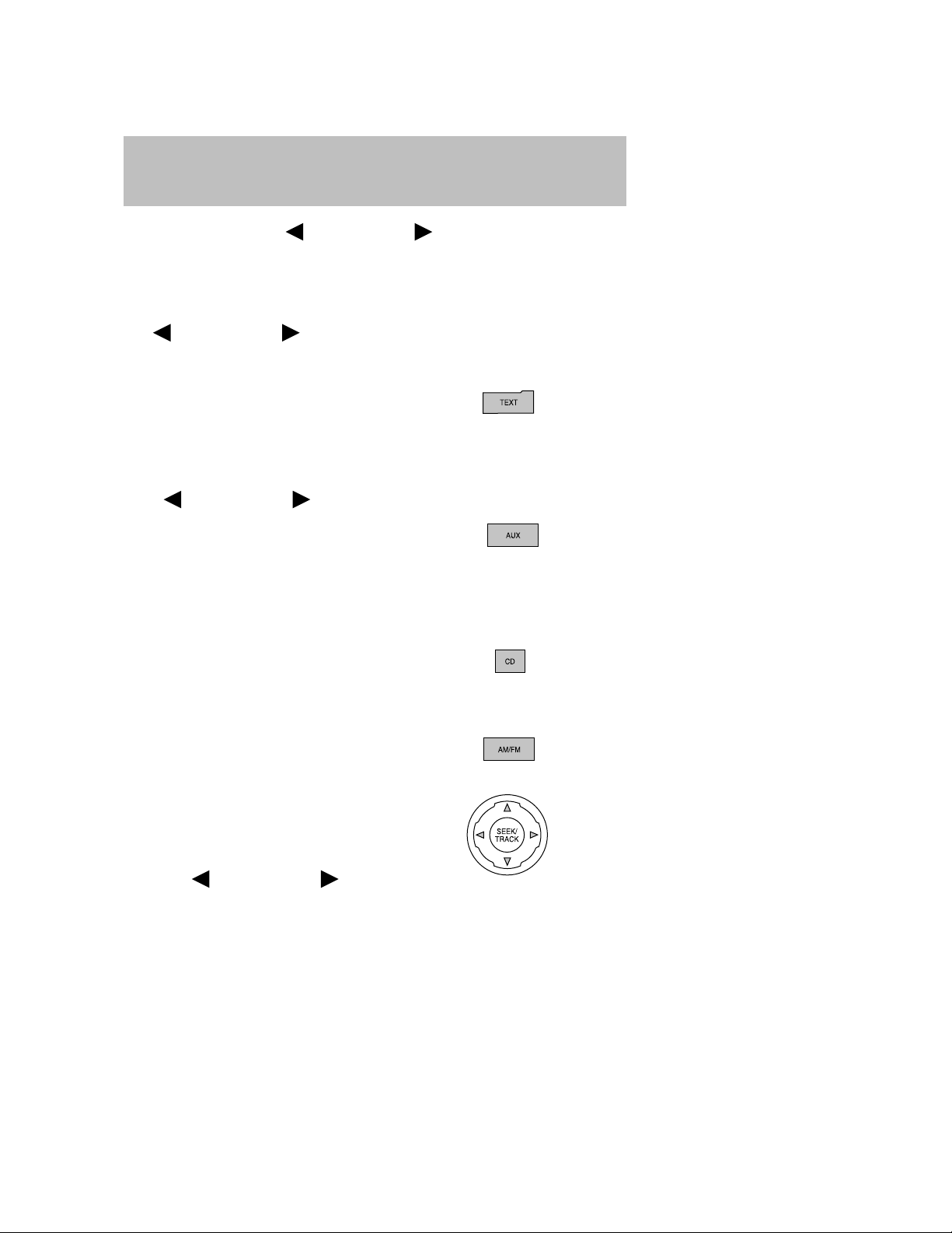
COMPRESSION: Available only in CD/MP3 mode. Press MENU until
COMPRESSION ON/OFF appears in the display.
Use
ON, the system will bring the soft and loud CD passages together for a
more consistent listening level.
7. TEXT: In MP3 mode, press
In TEXT MODE, sometimes the display requires additional text to be
displayed. When the</>indicator is active, press TEXT and then
press
8. AUX: Press AUX to access
9. SAT (Satellite Radio, if equipped): This control is not
10. CD: Press to enter CD/MP3
11. AM/FM: Press repeatedly to
12. SEEK/TRACK: In radio
SEEK/TRACK to toggle ON/OFF. When COMPRESSION is
TEXT repeatedly to view Album
(AL), Folder (FL), Song (SO)
and Artist (AR) in the display, if available.
SEEK/TRACK to view previous / additional display text.
LINE (auxiliary audio mode).
For location and further
information on auxiliary audio mode, refer to Auxiliary input jack
later in this chapter.
operational.
mode. If a disc is already loaded
into the system, CD/MP3 play
will begin where it ended last. If no CD is loaded, NO DISC will
appear in the display.
select AM/FM1/FM2 frequency
band.
mode, press to access the
previous/next strong radio
station.
In CD/MP3 mode,
press
access the previous/next track.
SEEK/TRACK to
22
2008 Tribute (j14)
Owners Guide (post-2002-fmt)
USA (fus)
Page 23
Entertainment Systems
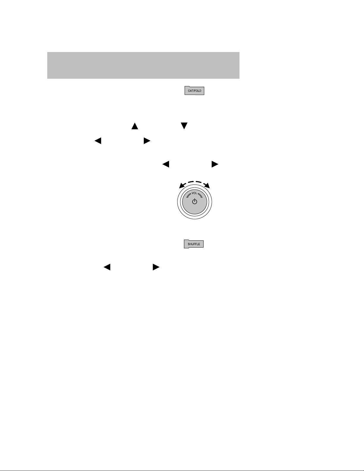
13. CAT (Category) /FOLD
(Folder):In Category mode,
use to select from various music
categories. To change RDS categories, ensure that RDS is ON in the
Menu listing. Press MENU again until RDS ON appears in the display.
Press CAT. PRESS UP OR DOWN TO CHANGE RDS CATEGORY will
appear in the display. Press
all possible categories. When the desired category appears in the
display, press
that selection or press SCAN for a brief sampling of all stations
playing that category of music.
In MP3 mode, press FOLD and then press
access the previous/next folder.
14. ON/OFF/VOL (Volume): Press
to turn ON/OFF. Turn to
increase/decrease volume.
Note: If the volume is set above a
certain level and the ignition is
turned off, the volume will come
back on at a “nominal” listening
level when the ignition switch is
turned back on.
15. SHUFFLE: In CD and MP3
mode,press SHUFFLE to
engage shuffle mode. SHUFFLE
ON will appear in the display. If you wish to engage shuffle mode
right away, press
Otherwise, random play will begin when the current track is finished
playing. SHUFFLE and the track # will appear in the display.
To disengage, press SHUFFLE again. SHUFFLE OFF will appear in
the display.
For a single CD system, the system will shuffle within the current
disc.
For a CDX6 system, the system will shuffle between all loaded discs.
The disc # will appear in the top left hand corner of the display.
SEEK/TRACK to find the next station playing
SEEK/TRACK to begin random play.
SEEK/TRACK to scroll through
SEEK/TRACK to
2008 Tribute (j14)
Owners Guide (post-2002-fmt)
USA (fus)
23
Page 24

Entertainment Systems
16. SCAN:In radio mode, press
for a brief sampling of all strong
radio stations.
In CD/MP3 mode, press for a brief sampling of all tracks on the
current disc or folder.
17. DIRECT: Press to access the
desired radio station, track or
MP3 folder.
In radio mode, press DIRECT and then press the desired radio
frequency (i.e. 101.1) using the memory presets.
In CD mode, press DIRECT. The display will read DIRECT TRACK
MODE SELECT TRACK. Enter the desired track number using the
numbered controls. The system will then begin playing that track.
In MP3 folder mode, press DIRECT and the number of the desired
folder. The system will advance to that specific folder.
18. LOAD: For a single CD
system, this control is not
operational. To load a CD,
simply insert the disc label side up into the CD slot.
For a CD6 system, press LOAD. When the display reads SELECT
SLOT, choose the desired slot number using memory presets 1–6.
When the display reads LOAD CD#, load the desired disc, label side
up. If you do not choose a slot within 5 seconds, the system will
choose for you. Once loaded, the first track will begin to play.
To auto load up to 6 discs, press and hold LOAD until the display
reads AUTOLOAD#. Load the desired disc, label side up. The system
will prompt you to load discs for the remaining available slots. Insert
the discs, one at a time, label side up, when prompted. Once loaded,
the disc in preset #1 will begin to play.
19. CD slot:For a single CD
system, insert a CD/MP3, label
side up.
For a CD6 system, press LOAD and select a CD slot using the
memory presets. When prompted by the system, insert a CD/MP3
label side up.
24
2008 Tribute (j14)
Owners Guide (post-2002-fmt)
USA (fus)
Page 25
Entertainment Systems
Auxiliary input jack
Your vehicle is equipped with an
Auxiliary Input Jack (AIJ). The
Auxiliary Input Jack provides a way
to connect your portable music
player to the in-vehicle audio
system. This allows the audio from a
portable music player to be played
through the vehicle speakers with
high fidelity. To achieve optimal
performance, please observe the
following instructions when
attaching your portable music
device to the audio system.
Required equipment:
1. Any portable music player designed to be used with headphones
2. An audio extension cable with stereo male 1/8 in. (3.5 mm)
connectors at each end
To play your portable music player using the auxiliary input jack:
1. Begin with the vehicle parked and the radio turned off.
2. Ensure that the battery in your portable music player is new or fully
charged and that the device is turned off.
3. Attach one end of the audio extension cable to the headphone
output of your player and the other end of the audio extension cable
to the AIJ in your vehicle.
4. Turn the radio on, using either a tuned FM station or a CD loaded
into the system. Adjust the volume to a comfortable listening level.
5. Turn the portable music player on and adjust the volume to 1/2 the
volume.
2008 Tribute (j14)
Owners Guide (post-2002-fmt)
USA (fus)
25
Page 26

Entertainment Systems
6. Press AUX on the vehicle radio repeatedly until LINE IN appears in
the display.
You should hear audio from your portable music player although it
may be low.
7. Adjust the sound on your portable music player until it reaches the
level of the FM station or CD by switching back and forth between
the AUX and FM or CD controls.
Troubleshooting:
1. Do not connect the audio input jack to a line level output. Line level
outputs are intended for connection to a home stereo and are not
compatible with the AIJ. The AIJ will only work correctly with
devices that have a headphone output with a volume control.
2. Do not set the portable music player’s volume level higher than is
necessary to match the volume of the CD or FM radio in your audio
system as this will cause distortion and will reduce sound quality.
Many portable music players have different output levels, so not all
players should be set at the same levels. Some players will sound
best at full volume and others will need to be set at a lower volume.
3. If the music sounds distorted at lower listening levels, turn the
portable music player volume down. If the problems persists, replace
or recharge the batteries in the portable music player.
4. The portable music player must be controlled in the same way
manner when it is used with headphones as the AIJ does not provide
control (play, pause, etc.) over the attached portable music player.
5. For safety reasons, connecting or adjusting the settings on your
portable music player should not be attempted while the vehicle is
moving. Also, the portable music player should be stored in a secure
location, such as the center console or the glove box, when the
vehicle is in motion. The audio extension cable must be long enough
to allow the portable music player to be safely stored while the
vehicle is in motion.
GENERAL AUDIO INFORMATION
Radio frequencies:
AM and FM frequencies are established by the Federal Communications
Commission (FCC) and the Canadian Radio and Telecommunications
Commission (CRTC). Those frequencies are:
AM: 530, 540–1700, 1710 kHz
FM: 87.7, 87.9–107.7, 107.9 MHz
26
2008 Tribute (j14)
Owners Guide (post-2002-fmt)
USA (fus)
Page 27
Entertainment Systems
Radio reception factors:
There are three factors that can affect radio reception:
• Distance/strength: The further you travel from an FM station, the
weaker the signal and the weaker the reception.
• Terrain: Hills, mountains, tall buildings, power lines, electric fences,
traffic lights and thunderstorms can interfere with your reception.
• Station overload: When you pass a broadcast tower, a stronger signal
may overtake a weaker one and play while the weak station frequency
is displayed.
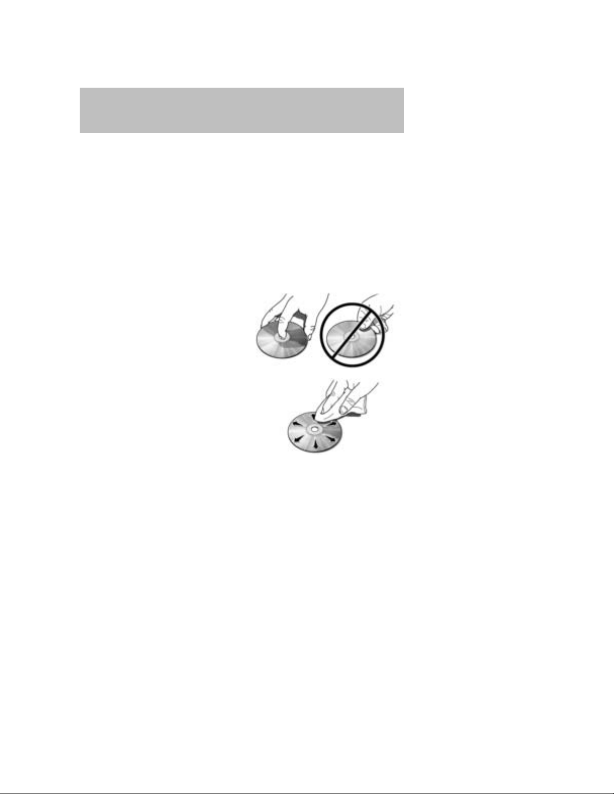
CD/CD player care
Do:
• Handle discs by their edges only.
(Never touch the playing
surface).
• Inspect discs before playing.
• Clean only with an approved CD
cleaner.
• Wipe discs from the center out.
Don’t:
• Expose discs to direct sunlight or heat sources for extended periods
of time.
• Clean using a circular motion.
CD units are designed to play commercially pressed 4.75 in (12 cm)
audio compact discs only. Due to technical incompatibility, certain
recordable and re-recordable compact discs may not function
correctly when used in Mazda CD players.
27
2008 Tribute (j14)
Owners Guide (post-2002-fmt)
USA (fus)
Page 28
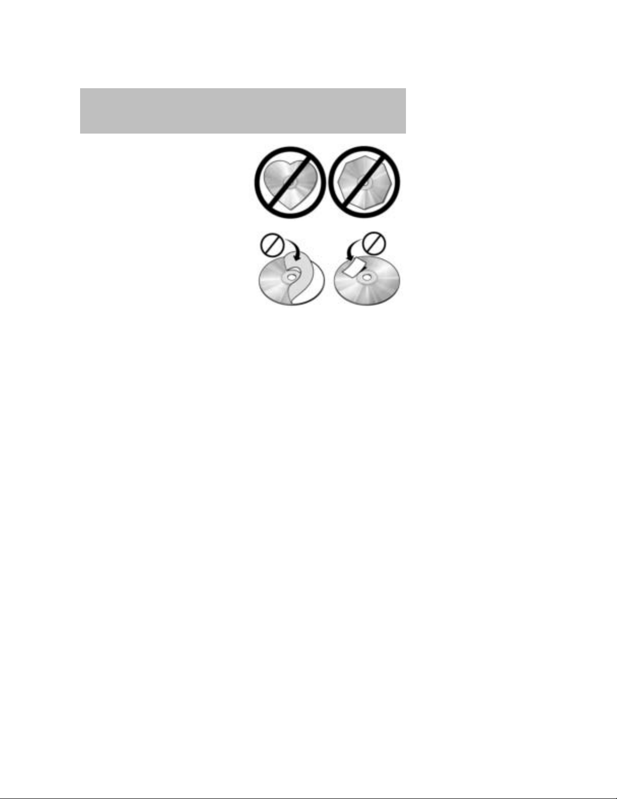
Entertainment Systems
Do not use any irregular shaped
CDs or discs with a scratch
protection film attached.
CDs with homemade paper
(adhesive) labels should not be
inserted into the CD player as
the label may peel and cause the
CD to become jammed. It is
recommended that homemade
CDs be identified with
permanent felt tip marker rather
than adhesive labels. Ballpoint pens may damage CDs. Please
contact your authorized dealer for further information.
Audio system warranty and service
Refer to the Warranty Information Booklet for audio system warranty
information. If service is necessary, see your authorized Mazda
dealership.
28
2008 Tribute (j14)
Owners Guide (post-2002-fmt)
USA (fus)
Page 29
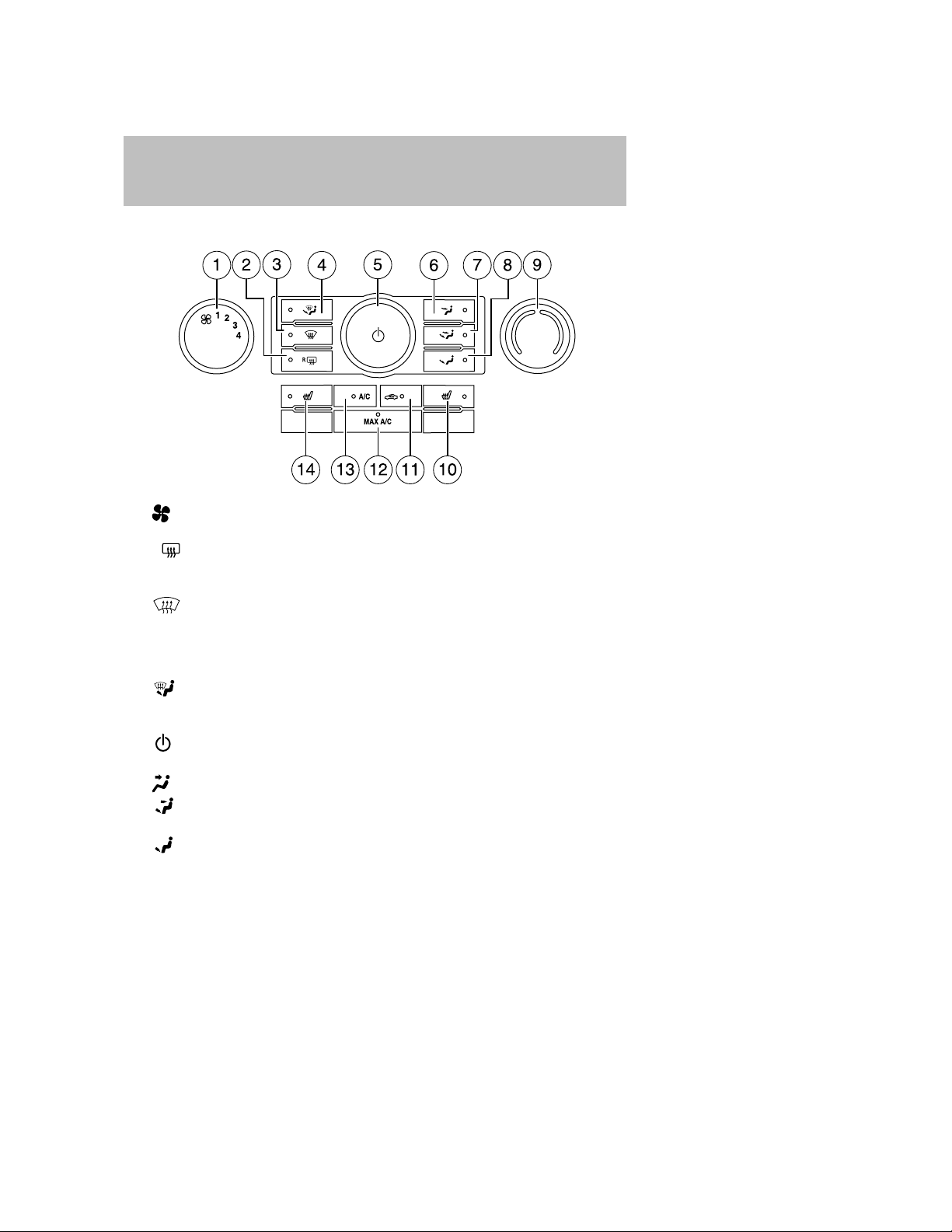
Climate Controls
MANUAL HEATING AND AIR CONDITIONING SYSTEM
Fan speed adjustment: Controls the volume of air circulated in
1.
the vehicle.
R
2.
3.
4.
5.
6.
7.
8.
9. Temperature control: Controls the temperature of the airflow in
Rear defroster: Press to activate/deactivate the rear window
defroster. Refer to Rear window defroster later in this chapter for
more information.
Defrost: Distributes outside air through the windshield
defroster vents and demister vents. Can be used to clear the
windshield of fog and thin ice. The system will automatically provide
outside air to reduce window fogging. Press this button again to
return to the previous air flow selection.
: Distributes air through the windshield defroster vents,
demister vents, floor vents and rear seat floor vents. The system will
automatically provide outside air to reduce window fogging.
Power: Press to activate/deactivate the climate control system.
When the system is off, outside air is shut out.
: Distributes air through the instrument panel vents.
: Distributes air through the instrument panel vents, demister
vents, floor vents and rear seat floor vents.
: Distributes air through the demister vents, floor vents and rear
seat floor vents.
the vehicle.
2008 Tribute (j14)
Owners Guide (post-2002-fmt)
USA (fus)
29
Page 30

Climate Controls
10. Passenger heated seat control (if equipped): Press to
activate/deactivate the passenger heated seat. See Heated seats in
the Seating and Safety Restraints chapter.
11.
recirculation in the vehicle. Recirculated air may reduce the amount
of time needed to cool down the interior of the vehicle and may also
help reduce undesired odors from reaching the interior of the
vehicle. Recirculated air engages automatically when MAX A/C is
selected or can be engaged manually in any airflow mode
except
all airflow modes except MAX A/C. When the ignition switch is
turned off and back on, the climate system will return to the
recirculated air mode only if the A/C button LED is illuminated and
the air distribution selection is either (panel) or (panel/floor).
12. MAX A/C: Distributes recirculated air through the instrument panel
vents to cool the vehicle. This re-cooling of the interior air is more
economical and efficient. Recirculated air may also help reduce
undesirable odors from entering the vehicle. Press the MAX A/C
button again for normal A/C operation.
13. A/C: Press to activate/deactivate air conditioning. Use with
recirculated air to improve cooling performance and efficiency.
Engages automatically in MAX A/C,
(floor/defrost).
14.
activate/deactivate the driver heated seat. See Heated seats in the
Seating and Safety Restraints chapter.
Outside temperature (if equipped): The outside temperature will
appear in the display and is labeled EXT TEMP.
Operating tips
• To reduce fog build up on the windshield during humid weather,
select
• To reduce humidity build up inside the vehicle, do not drive with the
system off or with
• Do not put objects under the front seats that will interfere with the
airflow to the back seats.
• Remove any snow, ice or leaves from the air intake area at the base of
the windshield.
• To improve the A/C cool down, drive with the windows slightly open
for 2-3 minutes after start up or until the vehicle has been “aired out.”
Recirculated air: Press to activate/deactivate air
(defrost). Recirculated air may turn off automatically in
(defrost) and
Driver heated seat control (if equipped): Press to
(defrost) or (floor/defrost).
(recirculated air) engaged and A/C off.
30
2008 Tribute (j14)
Owners Guide (post-2002-fmt)
USA (fus)
Page 31

Climate Controls
For maximum cooling performance in MAX A/C mode:
1. Select MAX A/C.
2. Move temperature control selector to the coolest setting.
3. Set the fan to the highest speed initially, then adjust to maintain
comfort.
To aid in side window defogging/demisting in cold weather:
1. Select
2. Select A/C.
3. Adjust the temperature control to maintain comfort.
4. Set the fan speed to the highest setting.
5. Direct the outer instrument panel vents towards the side windows.
To increase airflow to the outer instrument panel vents, close the vents
located in the middle of the instrument panel.
WARNING: Do not place objects on top of the instrument panel
as these objects may become projectiles in a collision or sudden
stop.
.
REAR WINDOW DEFROSTER
The rear defroster control is located on the climate control panel and
works to clear the rear window of fog and thin ice.
The engine must be running to operate the rear window defroster.
R
Press
the button will illuminate when active. The rear window defroster turns
off automatically after a predetermined amount of time, if a low battery
condition is detected or when the ignition is turned to the 1 (LOCK) or
2 (ACC) position. To manually turn off the rear window defroster at any
time, press the control again.
If your vehicle is equipped with both rear defroster and heated mirrors,
the same button will activate both. Refer to Heated outside mirrors in
the Driver Controls chapter.
Do not use razor blades or other sharp objects to clean the inside
of the rear window or to remove decals from the inside or the
rear window. This may cause damage to the heated grid lines and
will not be covered by your warranty.
to turn the rear window defroster on. An indicator light on
R
31
2008 Tribute (j14)
Owners Guide (post-2002-fmt)
USA (fus)
Page 32

Lights
HEADLAMP CONTROL
Rotate the headlamp control to the
first position to turn on the
parking lamps. Rotate to the second
position
headlamps.
Foglamp control (if equipped)
The headlamp control also operates
the foglamps. The foglamps can be
turned on when the headlamp
control is in the
positions and the high beams are
not turned on.
Pull headlamp control towards you
to turn foglamps on. The foglamp
indicator light
to turn on the
, or
will illuminate.
High beams
After turning the headlamps on,
push the lever toward the
instrument panel to activate. Pull
the lever towards you to deactivate.
32
2008 Tribute (j14)
Owners Guide (post-2002-fmt)
USA (fus)
Page 33

Lights
Flash to pass
Pull toward you slightly to activate
and release to deactivate.
Daytime running lamps (DRL) (if equipped)
Turns the lowbeam headlamps on with a reduced output.
To activate:
• the ignition must be in the 3 (RUN) position.
• the headlamp control must be in the OFF, parking lamps or autolamp
position.
• with automatic transmission, the transmission is not in P (Park),
• with manual transmission, the parking brake must be released.
WARNING: Always remember to turn on your headlamps at
dusk or during inclement weather. The Daytime Running Lamp
(DRL) system does not activate the tail lamps and generally
may not provide adequate lighting during these conditions.
Failure to activate your headlamps under these conditions may
result in a collision.
INSTRUMENT PANEL DIMMER CONTROL
Use to adjust the brightness of the
instrument panel and all applicable
switches in the vehicle during
headlamp and parklamp operation.
Move the control to the full upright
position, past detent, to turn on the
interior lamps.
Rotate to full down position (past
detent) to prevent interior lamps
from illuminating when the doors
are opened.
2008 Tribute (j14)
Owners Guide (post-2002-fmt)
USA (fus)
33
Page 34

Lights
AIMING THE HEADLAMPS
The headlamps on your vehicle are properly aimed at the assembly plant.
If your vehicle has been in an accident the alignment of your headlamps
should be checked by your authorized dealer.
Vertical aim adjustment
1. Park the vehicle directly in front of a wall or screen on a level
surface, approximately 25 feet (7.6 meters) away.
• (1) 8 feet (2.4 meter)
• (2) Center height of lamp to
ground
• (3) 25 feet (7.6 meters)
• (4) Horizontal reference line
2. Measure the height from the
center of your headlamp to the
ground and mark an 8 foot
(2.4 meter) horizontal reference
line on the vertical wall or
screen at this height (a piece of masking tape works well). The
center of the lamp is marked by a 3.0 mm circle on the headlamp
lens.
3. Turn on the low beam headlamps to illuminate the wall or screen
and open the hood. Cover the left-hand headlamp with an opaque
cloth.
4. On the wall or screen you will
observe a light pattern with a
distinct horizontal edge of high
intensity light towards the right.
If this edge is not at the
horizontal reference line, the
beam will need to be adjusted.
34
2008 Tribute (j14)
Owners Guide (post-2002-fmt)
USA (fus)
Page 35

Lights
5. Locate the vertical adjuster on
the headlamp, then usea4mm
socket to turn the adjuster
either counterclockwise (to
adjust up) or clockwise (to
adjust down) aligning the upper
edge of the light pattern to the
horizontal line.
6. Move the opaque cloth to cover
the right-hand headlamp and
repeat Steps 4 and 5 for the
left-hand headlamp.
7. HORIZONTAL AIM IS NOT REQUIRED FOR THIS VEHICLE AND IS
NON-ADJUSTABLE.
8. Close the hood and turn off the lamps.
TURN SIGNAL CONTROL
• Push down to activate the left
turn signal.
• Push up to activate the right turn
signal.
INTERIOR LAMPS
Cargo and dome lamp
Rear cargo lamp equipped with an
ON/OFF/DOOR control will light
when:
• the doors are closed and the
control is in the ON position.
• the control is in the DOOR
position and any door is open.
When the control is in the OFF position, it will not illuminate when you
open the doors.
2008 Tribute (j14)
Owners Guide (post-2002-fmt)
USA (fus)
35
Page 36

Lights
Dome lamps and map lamps
The front dome lamp is located overhead between the driver and
passenger seats.
The dome lamp control has three
positions:
• OFF: In this position, the lamp
will not illuminate.
• DOOR: In this position, the dome
lamp will illuminate only when a
door is opened and will remain
illuminated for 25 seconds after
the door is shut.
• ON: In this position, the lamp will remain illuminated.
The map lamp controls (without
moon roof) are located on the dome
lamp. Press the button on either
side of each map lamp to illuminate
the lamps. Push the button again to
turn off the lamps.
For models equipped with a moon
roof, the map lamps are located on
the moon roof control panel. Press
the button on either side of each
map lamp to illuminate the lamps.
Push the button again to turn off
the lamps.
The map lamps will illuminate
whenever a door is opened. After
the door is shut, the lamps will remain illuminated for 25 seconds.
BULB REPLACEMENT
Headlamp Condensation
The headlamps are vented to equalize pressure. When moist air enters
the headlamp(s) through the vents, there is a possibility that
condensation can occur. This condensation is normal and will clear
within 45 minutes of headlamp operation.
36
2008 Tribute (j14)
Owners Guide (post-2002-fmt)
USA (fus)
Page 37

Lights
Using the right bulbs
Replacement bulbs are specified in the chart below. Headlamp bulbs
must be marked with an authorized “D.O.T.” for North America to ensure
lamp performance, light brightness and pattern and safe visibility.
Note: The correct bulbs will not damage the lamp assembly or void the
lamp assembly warranty and will provide quality bulb burn time.
Function Number of bulbs Trade number
Headlamps (high and low
beams)
Park/turn lamps (front) 2 3457 NAK (amber)
Rear stop/tail/sidemarker 2 4157K
Backup lamp 2 921
Foglamp (front) 2 9145
Center High-mount stop
lamp
Rear license plate lamp 2 168
All replacement bulbs are clear in color except where noted.
To replace all instrument panel lights - see your authorized dealer
Replacing the interior bulbs
Check the operation of the following interior bulbs frequently:
• interior overhead lamp
• map lamp
For bulb replacement, see an authorized Mazda dealer.
2
5
H13
W5WL
Replacing exterior bulbs
Check the operation of all the bulbs frequently.
2008 Tribute (j14)
Owners Guide (post-2002-fmt)
USA (fus)
37
Page 38

Lights
Replacing headlamp bulbs
1. Make sure that the headlamp control is in the OFF position.
2. Open the hood.
3. Reach over the front bolster.
4. Remove the bulb by turning it
counterclockwise and then
pulling it straight out.
WARNING: Handling Halogen Bulbs: When a halogen bulb
breaks, it is dangerous. These bulbs contain pressurized gas. If
one is broken, it will explode and serious injuries could be
caused by the flying glass. If the glass portion of the bulb is
touched with bare hands, body oil could cause the bulb to
overheat and explode when lit. Never touch the glass portion of
the bulb with your bare hands and always wear eye protection
when handling or working around halogen bulbs.
5. Disconnect the electrical
connector from the bulb.
WARNING: Children and
Halogen Bulbs: Playing with a
halogen bulb is dangerous.
Serious injuries could be
caused by dropping a halogen
bulb or breaking in some other
way. Always keep halogen
bulbs out of the reach of
children.
6. Connect the electrical connector on the new bulb.
7. Insert the glass end of the new bulb into the headlamp assembly.
When the grooves in the plastic base are aligned, turn the new bulb
clockwise to install.
Replacing front parking lamp/turn signal bulbs
For bulb replacement, see your authorized Mazda dealer.
38
2008 Tribute (j14)
Owners Guide (post-2002-fmt)
USA (fus)
Page 39

Lights
Replacing tail/stop/turn/backup lamp bulbs
The tail/stop/turn/sidemarker/backup lamp bulbs are located in the same
portion of the tail lamp assembly, one just below the other. Follow the
same steps to replace either bulb:
1. Make sure the headlamp switch
is in the OFF position and then
open the liftgate to expose the
lamp assembly screws.
2. Remove the two screws from
the lamp assembly.
3. Carefully remove the lamp
assembly away from the vehicle
by pulling the assembly straight
out to expose the bulb socket.
DO NOT TIP THE LAMP ASSEMBLY SIDEWAYS.
4. Rotate the bulb socket counterclockwise and remove from lamp
assembly.
5. Pull bulb straight out of socket and push in the new bulb.
6. Install the bulb socket into the lamp assembly and rotate clockwise.
7. Carefully install the tail lamp assembly on the vehicle and secure
with two screws.
Replacing license plate lamp bulbs
1. Make sure the headlamp switch
is in the OFF position.
2. Depress the lever and carefully
pry the license plate lamp
assembly (located above the
license plate) from the liftgate.
3. Rotate the bulb socket
counterclockwise and remove
from lamp assembly.
2008 Tribute (j14)
Owners Guide (post-2002-fmt)
USA (fus)
39
Page 40

Lights
4. Pull bulb straight out of socket
and push in the new bulb.
5. Install the bulb socket into the
lamp assembly and rotate
clockwise.
6. To install, carefully press the
lamp assembly into liftgate.
Replacing high-mount brake lamp bulbs
To remove the lamp assembly:
1. Remove the two screws and
move the lamp assembly away
from the liftgate.
2. Remove the bulb holder from
the lamp assembly by
depressing the snaps.
3. Pull the bulb straight out of the
socket and push in the new
bulb.
To complete installation, follow the
removal procedure in reverse order.
40
2008 Tribute (j14)
Owners Guide (post-2002-fmt)
USA (fus)
Page 41

Replacing foglamp bulbs (if equipped)
1. Make sure the foglamp switch is
in the OFF position.
2. From underneath the vehicle,
rotate the harness/bulb
assembly counterclockwise, to
remove from the fog lamp.
3. Carefully disconnect the bulb
from the harness assembly via
the two snap clips.
Install the new bulb in reverse order.
Lights
2008 Tribute (j14)
Owners Guide (post-2002-fmt)
USA (fus)
41
Page 42

Driver Controls
MULTI-FUNCTION LEVER
Windshield wiper: Rotate the end
of the control away from you to
increase the speed of the wipers;
rotate towards you to decrease the
speed of the wipers.
Windshield washer: Push the end
of the stalk:
• briefly: causes a single swipe of
the wipers without washer fluid.
• a quick push and hold: the wipers
will swipe three times with
washer fluid.
• a long push and hold: the wipers and washer fluid will be activated for
up to ten seconds.
Courtesy wipe feature: One extra wipe will happen a few seconds
after washing the front window to clear any water that is dripping down
from the top of the windshield caused by the washing.
Note: Do not operate the washer when the washer reservoir is empty.
This may cause the washer pump to overheat. Check the washer fluid
level frequently. Do not operate the wipers when the windshield is dry.
This may scratch the glass, damage the wiper blades and cause the wiper
motor to burn out. Before operating the wiper on a dry windshield,
always use the windshield washer. In freezing weather, be sure the wiper
blades are not frozen to the windshield before operating the wipers.
Rear window wiper/washer controls
For rear wiper operation, rotate the
rear window wiper and washer
control to the desired position.
Select:
INT 2 — Normal speed operation of
rear wiper.
INT 1 — Intermittent operation of
rear wiper.
OFF — Rear wiper and washer off.
42
2008 Tribute (j14)
Owners Guide (post-2002-fmt)
USA (fus)
Page 43

Driver Controls
For rear wash cycle, rotate (and hold as desired) the rear wiper/washer
control to either
From either position, the control will automatically return to the INT 2
or OFF position.
MANUAL TILT STEERING COLUMN
To adjust the steering wheel:
1. Pull down the steering column
tilt lever.
2. Move the steering wheel up or
down until you find the desired
location.
3. Push the steering column tilt
lever up. This will lock the
steering wheel in position.
WARNING: Adjusting the
steering wheel while the
vehicle is moving is dangerous.
Moving it can very easily cause
the driver to abruptly turn to
the left or right. This can lead
to loss of control or an
accident. Never adjust the
steering wheel while the
vehicle is moving.
position.
2008 Tribute (j14)
Owners Guide (post-2002-fmt)
USA (fus)
43
Page 44

Driver Controls
ILLUMINATED VISOR MIRROR (IF EQUIPPED)
Lift the mirror cover to turn on the
visor mirror lamps.
OVERHEAD CONSOLE (IF EQUIPPED)
The appearance of your vehicle’s overhead console will vary according to
your option package.
Storage compartment (if equipped)
Press the OPEN control to open the
storage compartment. The door will
open slightly and can be moved to
full open.
CENTER CONSOLE
Your vehicle is equipped with a variety of console features. These
include:
1. Cupholders
2. Utility compartment console lid
has a CD holder, a business card
holder and two pen holders.
The utility compartment has a
removable bin with coin holder
slots, a sliding tray, a cell phone
holder and CD holders
3. Rear power point
4. Rear cupholders
5. Small storage trays
WARNING: Use only soft cups in the cupholders. Hard objects
can injure you in a collision.
44
2008 Tribute (j14)
Owners Guide (post-2002-fmt)
USA (fus)
Page 45

The tray and inside bin can be
removed to open up space to fit a
laptop computer, MP3 players, CDs
or handbags. To remove, open the
console lid and pull the bin straight
up and out from the console
housing.
The sliding tray and inside bin can
be hooked on the side or rear of the
console for extra storage.
Driver Controls
2008 Tribute (j14)
Owners Guide (post-2002-fmt)
USA (fus)
45
Page 46

Driver Controls
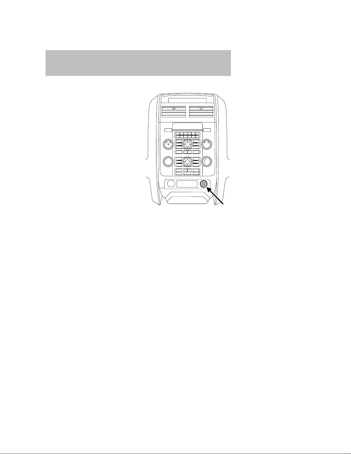
AUXILIARY POWER POINT (12VDC)
WARNING: Power outlets are designed for accessory plugs
only. Do not insert any other object in the power outlet as this
will damage the outlet and blow the fuse. Do not hang any type
of accessory or accessory bracket from the plug. Improper use
of the power outlet can cause damage not covered by your
warranty.
The auxiliary power point is located
on the center console in front of the
gearshift.
Do not use the power point for
operating the cigarette lighter
element (if equipped).
To prevent the fuse from being
blown, do not use the power
point(s) over the vehicle capacity of
12 VDC/180W. If the power point or
cigar lighter socket is not working, a fuse may have blown. Refer to
Fuses and Relays in the Roadside Emergencies chapter for information
on checking and replacing fuses.
To prevent the battery from being discharged, do not use the power
point longer than necessary when the engine is not running.
Cigarette/Cigar lighter (if equipped)
Do not plug optional electrical accessories into the cigarette lighter
socket.
Do not hold the lighter in with your hand while it is heating, this will
damage the lighter element and socket. The lighter will be released from
its heating position when it is ready to be used.
Improper use of the lighter can cause damage not covered by your
warranty.
46
2008 Tribute (j14)
Owners Guide (post-2002-fmt)
USA (fus)
Page 47

Driver Controls
POWER WINDOWS
WARNING: Do not leave children unattended in the vehicle and
do not let children play with the power windows. They may
seriously injure themselves.
WARNING: When closing the power windows, you should verify
they are free of obstructions and ensure that children and/or
pets are not in the proximity of the window openings.
Press and pull the window switches
to open and close windows.
• Push down (to the first detent)
and hold the switch to open.
• Pull up (to the first detent) and
hold the switch to close.
One touch down
Allows the driver’s window to open
fully without holding the control
down. Push the switch completely
down to the second detent and
release quickly. The window will
open fully. Momentarily press the
switch to any position to stop the
window operation.
AUTO
Window lock
The window lock feature allows only
the driver to operate the power
windows.
To lock out all the window controls
except for the driver’s press the
right side of the control. Press the
left side to restore the window
controls.
2008 Tribute (j14)
Owners Guide (post-2002-fmt)
USA (fus)
47
Page 48

Driver Controls
Accessory delay
With accessory delay, power windows and moonroof operate for up to
ten minutes after the ignition switch is turned from the ACC or ON to
the OFF position, the key is not in the ignition or until either front door
is opened.
WARNING: Do not leave children unattended in the vehicle and
do not let children play with the power windows or moon roof.
They may seriously injure themselves.
INTERIOR MIRROR
The interior rear view mirror has two pivot points on the support arm
which lets you adjust the mirror UP or DOWN and from SIDE to SIDE.
WARNING: Do not adjust the mirror while the vehicle is in
motion.
EXTERIOR MIRRORS
Power side view mirrors
To adjust your mirrors:
1. Rotate the control clockwise to
adjust the right mirror and
rotate the control
counterclockwise to adjust the
left mirror.
2. Move the control in the
direction you wish to tilt the
mirror.
3. Return to the center position to lock mirrors in place.
48
2008 Tribute (j14)
Owners Guide (post-2002-fmt)
USA (fus)
Page 49

Fold-away mirrors
Fold the side mirrors in carefully
when driving through a narrow
space, like an automatic car wash.
Driver Controls
Heated outside mirrors
Both mirrors are heated
automatically to remove ice, mist
and fog when the rear window
defrost is activated.
Do not remove ice from the
mirrors with a scraper or
attempt to readjust the mirror
glass if it is frozen in place.
These actions could cause damage to the glass and mirrors.
CRUISE CONTROL/SPEED CONTROL (IF EQUIPPED)
With cruise control/speed control set, you can maintain a set speed
without keeping your foot on the accelerator pedal.
WARNING: Using cruise control in the following conditions
could cause you to lose control of the vehicle:
• Heavy or unsteady traffic
• Slippery or winding roads
• Similar restrictions that require inconsistent speed
Don’t use cruise control in these situations.
(if equipped)
2008 Tribute (j14)
Owners Guide (post-2002-fmt)
USA (fus)
49
Page 50

Driver Controls
Setting speed control
The controls for using your speed
control are located on the steering
wheel for your convenience.
1. Press the ON control and
release it.
2. Accelerate to the desired speed.
3. Press the SET + control and
release it.
4. Take your foot off the
accelerator pedal.
5. The indicator light
instrument cluster will turn on.
Note:
• Vehicle speed may vary momentarily when driving up and down a
steep hill.
• If the vehicle speed increases above the set speed on a downhill, you
may want to apply the brakes to reduce the speed.
• If the vehicle speed decreases more than 10 mph (16 km/h) below
your set speed on an uphill, your speed control will disengage.
• If the vehicle speed decreases to 30 mph (48 km/h) or less, your
speed control will disengage
Disengaging speed control
To disengage the speed control:
• Depress the brake pedal
Disengaging the speed control will not erase previous set speed.
Note: When you use the clutch pedal to disengage the speed control,
the engine speed may briefly increase, this is normal.
on the
50
2008 Tribute (j14)
Owners Guide (post-2002-fmt)
USA (fus)
Page 51

Driver Controls
Resuming a set speed
Press the RESUME control and
release it. This will automatically
return the vehicle to the previously
set speed.
Increasing speed while using speed control
There are three ways to set a higher
speed:
• Press and hold the SET + control
until you get to the desired
speed, then release the control.
• Press and release the SET +
control to operate the Tap-Up
function. Each tap will increase
the set speed by 1 mph (1.6 km/h).
• Use the accelerator pedal to get
to the desired speed. When the vehicle reaches that speed press and
release the SET + control.
Reducing speed while using speed control
There are three ways to reduce a
set speed:
• Press and hold the CST - control
until you get to the desired
speed, then release the control.
• Press and release the CST control to operate the Tap-Down
function. Each tap will decrease
the set speed by 1 mph (1.6 km/h).
2008 Tribute (j14)
Owners Guide (post-2002-fmt)
USA (fus)
51
Page 52

Driver Controls
• Depress the brake pedal or the
clutch pedal (if equipped) until
the desired vehicle speed is
reached, press the SET + control.
Turning off speed control
There are two ways to turn off the
speed control:
• Press the speed control OFF
control.
• Turn OFF the ignition.
Note: When you turn off the speed
control or the ignition, your speed
control set speed memory is erased.
STEERING WHEEL CONTROLS (IF EQUIPPED)
These controls allow you to operate some audio control features.
Radio control features
Press MEDIA to select:
• AM, FM1, FM2, or CD
• LINE IN (Auxiliary input jack) (if
equipped)
52
2008 Tribute (j14)
Owners Guide (post-2002-fmt)
USA (fus)
Page 53

Driver Controls
In Radio mode:
• Press
next/previous preset station.
In CD mode:
• Press
next track on the disc.
In any mode:
• Press VOL + or - to adjust the
volume.
MOON ROOF (IF EQUIPPED)
WARNING: Do not let children play with the moon roof or
leave children unattended in the vehicle. They may seriously
hurt themselves.
to access the
to listen to the
WARNING: When closing the moon roof, you should verify that
it is free of obstructions and ensure that children and/or pets
are not in the proximity of the moon roof opening.
2008 Tribute (j14)
Owners Guide (post-2002-fmt)
USA (fus)
53
Page 54

Driver Controls
To operate the moon roof:
• The moon roof is equipped with
an automatic, one-touch, express
opening feature. Press and
release the rear portion of the
control. To stop motion at any
time during the one-touch
opening, press the control again.
• To close, press and hold the front
portion of the control.
To operate the moon roof vent position:
• To open, press and hold the front portion of the control. This will
open the vent.
• To close, press and hold the rear portion of the control.
NOTE: If the battery is disconnected, discharged, or a new battery is
installed, the moon roof needs to be opened to the vent position to reset
the moon roof positions.
NOTE: If you open and close the moon roof repeatedly, the moon roof
motor may overheat and shut down for 45 seconds while the motor
cools.
LIFTGATE
• To open the liftgate window,
unlock the liftgate (with the
power door locks or the remote
entry) and push the right side
control button under the license
plate lamp shield.
• To open the liftgate, unlock the
liftgate (with the power door
locks or the remote entry) and
push the middle control button
under the license plate lamp
shield.
To lock the liftgate and the liftgate window, use the power door locks.
Do not open the liftgate or liftgate glass in a garage or other enclosed
area with a low ceiling. If the liftgate glass is raised and the liftgate is
also opened, both liftgate and glass could be damaged against a low
ceiling.
54
2008 Tribute (j14)
Owners Guide (post-2002-fmt)
USA (fus)
Page 55

Driver Controls
Do not leave the liftgate or liftgate glass open while driving. Doing so
could cause serious damage to the liftgate and its components as well as
allowing carbon monoxide to enter the vehicle.
WARNING: Make sure that the liftgate door and/or window are
closed to prevent exhaust fumes from being drawn into the
vehicle. Exhaust fumes contain carbon monoxide which can
injure your lungs and cause drowsiness and even death. This
will also prevent passengers and cargo from falling out. If you
must drive with the liftgate door or window open, keep the
vents open so outside air comes into the vehicle.
CARGO AREA FEATURES
Cargo shade (if equipped)
If your vehicle has a cargo shade, you can use it to cover items in the
cargo area of your vehicle.
To install the shade:
• Insert the ends of the cargo
shade into the mounting features
located behind the rear seat on
the rear trim panels.
To operate the shade:
1. Grasp the handle at the rear
edge of the shade and pull
rearward.
2. Secure both ends of the support
rod into the retention slots located on the rear quarter trim panels.
WARNING: Ensure that the posts are properly latched in
mounting features. The cover may cause injury in a sudden stop
or accident if it is not securely installed.
WARNING: Do not place any objects on the cargo area shade.
They may obstruct your vision or strike occupants of vehicle in
the case of a sudden stop or collision.
2008 Tribute (j14)
Owners Guide (post-2002-fmt)
USA (fus)
55
Page 56

Driver Controls
WARNING: Not securing luggage or cargo while driving is
dangerous as it could move or be crushed during sudden
braking or a collision and cause injury. Make sure luggage and
cargo is secured before driving.
Cargo management system (if equipped)
The cargo management system consists of two storage compartments
located in the floor of the rear cargo area.
1. The larger, rearward,
compartment is for customer
storage.
• To open, lift the lid with the
pull latch. The lid can be
removed to allow for flexible
storage.
• To close, lower the lid and
press down at the latch area
until you hear the latch engage.
A pad lock or combination lock
can be applied to use the lockable storage feature on the large
customer storage bin.
2. The smaller compartment contains the jack kit. There is also extra
storage space for customer use. The lid on the small compartment is
accessible and secured by two snap features.
WARNING: This storage compartment is not designed to
restrain objects during a collision with the lid removed.
56
2008 Tribute (j14)
Owners Guide (post-2002-fmt)
USA (fus)
Page 57

LUGGAGE RACK
Your vehicle is equipped with a roof
rack. The maximum load for the
roof rack is 100 lbs (44 kg), evenly
distributed on the cross-bars. If it is
not possible to evenly distribute the
load, position it in the center or as
far forward on the cross-bars as
possible.
Do not use the vehicle’s door
handles as tie down loops. Use
the tie-down loops on the
thumbwheels to secure load.
To adjust the cross-bar (if equipped) position:
1. Loosen the thumbwheel at both
ends of the cross-bar (both
cross-bars are adjustable).
2. Slide the cross-bar to the
desired location.
3. Tighten the thumbwheel at both
ends of the cross-bar.
Driver Controls
2008 Tribute (j14)
Owners Guide (post-2002-fmt)
USA (fus)
57
Page 58

Driver Controls
To remove the cross-bar assembly (if equipped) from the roof rack side rails:
1. Loosen the thumbwheel at both
ends of the cross-bar (both
cross-bars are adjustable).
2. Slide the cross-bar to the end of
the rail.
3. Use a long, flat object to
depress the tongue in the
endcaps on both sides of the
cross-bar.
4. Slide the cross-bar assembly off
the end of the rail.
58
2008 Tribute (j14)
Owners Guide (post-2002-fmt)
USA (fus)
Page 59

Driver Controls
To reinstall the cross-bar assembly (if equipped) to the roof rack side rails:
1. Ensure that both cross-bar
assemblies are installed with the
F (front) arrow facing towards
the front of the vehicle.
2. Use a long, flat object to
depress the tongue in the
endcaps on both sides of the
cross-bar.
3. Slide the cross-bar assemblies
over the end cap tongue and
into the side rails.
4. Tighten thumbwheel at both
ends of the cross-bar.
2008 Tribute (j14)
Owners Guide (post-2002-fmt)
USA (fus)
59
Page 60

Locks and Security
KEYS
Your vehicle is equipped with two
Integrated Keyhead Transmitters
(IKTs). The IKT functions as both a
programmed ignition key that
operates all the locks and starts the
vehicle, and a remote keyless entry
transmitter.
Your IKTs are programmed to your vehicle; using a non-programmed key
will not permit your vehicle to start. If you lose your authorized dealer
supplied IKTs, replacement IKTs are available through your authorized
dealer. Standard SecuriLock娂 keys without remote entry transmitter
functionality can also be purchased from your authorized dealer if
desired.
Always carry a spare key with you in case of an emergency.
For more information regarding programming replacement IKTs, refer to
the SecuriLock娂 passive anti-theft system section later in this chapter.
Note: Your vehicle’s IKTs were
issued with an adhesive security
label on them that provides
important vehicle key cut
information. It is recommended that
you maintain the label in a safe
place for future reference, such as
the inside front cover of this
Owner’s Manual.
60
2008 Tribute (j14)
Owners Guide (post-2002-fmt)
USA (fus)
Page 61

Locks and Security
RECOMMENDED HANDLING OF THE INTEGRATED KEYHEAD TRANSMITTER (IKT)
To avoid inadvertently activating the remote entry functions of your
vehicle, it is recommended that the Integrated Keyhead Transmitter
(IKT) be handled properly when starting and turning off your vehicle.
When inserting the IKT into the
ignition cylinder, place your thumb
on the center thumb rest of the IKT
and forefinger on the logo badge on
the opposite side.
To gain more leverage when rotating
the IKT in the ignition lock cylinder,
you can readjust the location of
your thumb to grasp the IKT on the
outer edge next to the
control.
Likewise, when rotating the IKT to
the 1 (LOCK) position in the
ignition lock cylinder, the bottom
edge of the IKT adjacent to the
control can be utilized.
2008 Tribute (j14)
Owners Guide (post-2002-fmt)
USA (fus)
61
Page 62

Locks and Security
POWER DOOR LOCKS
• Press the
doors.
• Press the
doors.
Door key unlocking/locking
Unlocking the doors
Turn the key in the door cylinder to unlock the driver’s door only. All
other doors will remain locked.
Locking the doors
Turn the key in the door cylinder to lock the driver’s door only.
Smart unlocking feature
The smart unlocking feature helps prevent you from locking yourself out
of the vehicle. With the key in any ignition position, the driver’s door will
automatically unlock if it is locked using the power lock control on the
driver’s door panel while the driver’s door is open.
CHILDPROOF DOOR LOCKS
When these locks are set, the rear
doors cannot be opened from the
inside. The rear doors can be
opened from the outside when the
doors are unlocked.
The childproof locks are located on
rear edge of each rear door and
must be set separately for each
door.
NOTE: Setting the lock for one
door will not automatically set the
lock for both doors so you must set
each child lock on each door
separately.
Insert the key and turn in the direction of arrow shown on the door to
engage the child proof lock. Turn in the opposite direction to disengage
childproof locks.
control to unlock all
control to lock all
62
2008 Tribute (j14)
Owners Guide (post-2002-fmt)
USA (fus)
Page 63

Locks and Security
REMOTE ENTRY SYSTEM (IF EQUIPPED)
The Integrated Keyhead Transmitter (IKT) complies with part 15 of the
FCC rules and with RSS-210 of Industry Canada. Operation is subject to
the following two conditions: (1) This device may not cause harmful
interference, and (2) This device must accept any interference received,
including interference that may cause undesired operation.
Changes or modifications not expressly approved by the party
responsible for compliance could void the user’s authority to
operate the equipment.
The typical operating range for your
IKT is approximately 33 feet
(10 meters). A decrease in
operating range could be caused by:
• weather conditions,
• nearby radio towers,
• structures around the vehicle, or
• other vehicles parked next to
your vehicle.
The IKT allows you to:
• remotely unlock the vehicle
doors.
• remotely lock all the vehicle
doors.
• remotely open the power liftgate glass.
• activate the personal alarm.
• operate the illuminated entry feature.
The remote entry lock/unlock feature operates in any ignition position
except while the key is held in the 4 (START) position. The panic
feature operates with the key in the 1 (LOCK) position.
If there are problems with the remote entry system, make sure to take
ALL Integrated Keyhead Transmitters with you to the authorized
dealer in order to aid in troubleshooting the problem.
2008 Tribute (j14)
Owners Guide (post-2002-fmt)
USA (fus)
63
Page 64

Locks and Security
Two step door unlocking
1. Press and release to unlock the driver’s door. Note: The interior
lamps will illuminate if the control on the overhead lamp is in the
DOOR position.
2. Press
passenger doors, the liftgate and liftgate glass.
One step door unlocking
If the one step door unlocking feature is activated, press
once to unlock all of the doors, the liftgate and liftgate glass. Note: The
interior lamps will illuminate (refer to the Illuminated entry feature
later in this section), if the control on the overhead lamp is in the DOOR
position.
Switching from two step to one step door unlocking
Unlocking can be switched between two step and one step door
unlocking by pressing and holding both
simultaneously on the remote entry transmitter for approximately
4 seconds. The turn signal will flash twice to indicate that the vehicle has
switched to one step unlocking. Repeat the procedure to switch back to
two step unlocking.
Locking the doors
1. Press
and the liftgate are properly closed, the park/turn lamps will flash
once.
2. Press
the doors and liftgate are closed and locked. Note: The doors will
lock again and the horn will chirp once.
If any of the doors or the hood are not properly closed, the horn will
chirp twice and park/turn lamps will not flash when the
pressed.
and release again within three seconds to unlock the
and release
and buttons
and release to lock all the doors. Assuming all vehicle doors
and release again within three seconds to confirm that all
control is
Opening the liftgate (if equipped)
Press twice within 3 seconds to open the liftgate glass.
Car finder
Press
will flash. It is recommended that this method be used to locate your
vehicle, rather than using the panic alarm.
64
twice within 3 seconds. The horn will chirp and the turn lamps
2008 Tribute (j14)
Owners Guide (post-2002-fmt)
USA (fus)
Page 65

Locks and Security
Sounding a panic alarm
Press and hold
the feature, press the control again, turn the ignition to the 3 (ON) or
4 (START) position, or wait for the alarm to time out in approximately
3 minutes.
Note: The panic alarm will only operate when the ignition is in the
1 (LOCK) position.
Replacing the battery
The Integrated Keyhead Transmitter uses one coin type three-volt
lithium battery CR2032 or equivalent.
To replace the battery:
1. Twist a thin coin in the slot of
the IKT near the key ring in
order to remove the battery
cover.
2. Do not wipe off any grease on
the battery terminals on the
back surface of the circuit
board.
for 1.5 secondsto activate the alarm. To deactivate
3. Remove the old battery. Note: Please refer to local regulations when
disposing of transmitter batteries.
4. Insert the new battery. Refer to the instructions inside the IKT for
the correct orientation of the battery. Press the battery down to
ensure that the battery is fully seated in the battery housing cavity.
5. Snap the battery cover back onto the key.
Note: Replacement of the battery will not cause the IKT to become
deprogrammed from your vehicle. The IKT should operate normally after
battery replacement.
65
2008 Tribute (j14)
Owners Guide (post-2002-fmt)
USA (fus)
Page 66

Locks and Security
Replacing lost Integrated Keyhead Transmitters (IKTs)
If you would like to have your Integrated Keyhead Transmitters
reprogrammed because you lost one, or would like to buy additional
IKTs, you can either reprogram them yourself, or take all IKTs to your
authorized dealer for reprogramming.
How to reprogram your Integrated Keyhead Transmitters (IKTs)
To program a new Integrated Keyhead Transmitter yourself, refer to
Programming spare keys in the SecuriLock娂 passive anti-theft
section of this chapter. Note: At least two IKTs are required to perform
this procedure yourself.
Illuminated entry
The interior lamps and puddle lamps (if equipped) illuminate when the
Integrated Keyhead Transmitter or the keyless entry system keypad is
used to unlock the door(s).
The illuminated entry system will turn off the interior lights if:
• the ignition is turned to the 3 (RUN) position, or
• the Integrated Keyhead Transmitter lock control is pressed, or
• the vehicle is locked using the keyless entry keypad (if equipped), or
• after 25 seconds of illumination.
The inside lights will not turn off if:
• they have been turned on with the dimmer control, or
• any door is open.
Perimeter lamps illuminated entry
With the Integrated Keyhead Transmitter system, the following items will
illuminate when the
• Head lamps
• Park lamps
• Tail lamps
The lamps will automatically turn off:
• if the ignition switch is turned to the 3 (RUN) position, or
• the IKT
• after 25 seconds of illumination.
Note: On some vehicles, the perimeter lamps illuminated entry feature
will not activate in daylight conditions.
66
(lock) control is pressed, or
(unlock) control on the transmitter is pressed:
2008 Tribute (j14)
Owners Guide (post-2002-fmt)
USA (fus)
Page 67

Locks and Security
Deactivating/activating perimeter lamps illuminated entry
You may enable/disable this feature by having your vehicle serviced by
your authorized dealer.
You may also perform the following power door lock sequence to
enable/disable the perimeter lamps feature. Note: Before starting, ensure
the ignition is in the 1 (LOCK) position and all vehicle doors are closed.
You must complete Steps 1–5 within 30 seconds or the procedure will
have to be repeated. If the procedure needs to be repeated, wait a
minimum of 30 seconds before beginning again.
1. The ignition must be OFF to
begin the sequence.
2. Place the key in the ignition and
turn the ignition to the 3 (RUN)
position.
3. Press the power door unlock
control on the door panel three
times.
4. Turn the ignition from the 3
(RUN) position to the 1 (LOCK)
position.
5. Press the power door unlock control on the door panel three times.
6. Turn the ignition back to the 3 (RUN) position. The horn will chirp
one time to confirm programming mode has been entered and is
active.
7. Press the power door unlock control twice within 5 seconds. Note:
The horn will chirp once to indicate the perimeter lighting feature
has been deactivated. The horn will chirp once and honk once (one
short and one long) to indicate the perimeter lighting feature has
been activated.
8. Turn the ignition to the 1 (LOCK) position to exit the procedure.
Note: The horn will chirp once to confirm the procedure is
complete.
Illuminated exit
• The interior lights will illuminate when the key is removed from the
ignition.
The lamps automatically turn off after 25 seconds. The dome and cargo
lamp controls must not be set to the OFF position for the illuminated
exit system to operate.
2008 Tribute (j14)
Owners Guide (post-2002-fmt)
USA (fus)
67
Page 68

Locks and Security
SECURILOCK姟 PASSIVE ANTI-THEFT SYSTEM
SecuriLock娂 passive anti-theft system is an engine immobilization
system. This system is designed to help prevent the engine from being
started unless a coded Integrated Keyhead Transmitter (IKT)
programmed to your vehicle is used. The use of the wrong type of
coded key may lead to a “no-start” condition.
Your vehicle comes with two coded Integrated Keyhead Transmitters;
additional coded IKTs may be purchased from your authorized dealer.
Standard SecuriLock娂 keys without remote entry transmitter
functionality can also be purchased from your authorized dealer if
desired. The authorized dealer can program your spare IKTs to your
vehicle or you can program the IKTs yourself. Refer to Programming
spare Integrated Keyhead Transmitters for instructions on how to
program the coded key.
Note: The SecuriLock娂 passive anti-theft system is not compatible with
non-Mazda aftermarket remote start systems. Use of these systems may
result in vehicle starting problems and a loss of security protection.
Note: Large metallic objects, electronic devices that are used to
purchase gasoline or similar items, or a second coded key on the same
key chain may cause vehicle starting issues. You need to prevent these
objects from touching the coded IKT while starting the engine. These
objects will not cause damage to the coded IKT, but may cause a
momentary issue if they are too close to the IKT when starting the
engine. If a problem occurs, turn the ignition off, remove all objects on
the key chain away from the coded IKT and restart the engine.
Anti-theft indicator
The anti-theft indicator is located in the instrument panel cluster.
• When the ignition is in the 1
(LOCK) position, the indicator
will flash once every 2 seconds to
indicate the SecuriLock娂 system
is functioning as a theft deterrent.
• When the ignition is in the 3 (RUN) position, the indicator will glow
for 3 seconds to indicate normal system functionality.
If a problem occurs with the SecuriLock娂 system, the indicator will flash
rapidly or glow steadily when the ignition is in the 3 (RUN) position. If
this occurs, the vehicle will not start and should be taken to an
authorized dealer for service.
68
2008 Tribute (j14)
Owners Guide (post-2002-fmt)
USA (fus)
Page 69

Locks and Security
Automatic arming
The vehicle is armed immediately after switching the ignition to the
1 (LOCK) position.
The theft indicator will flash every
two seconds to act as a theft
deterrent when the vehicle is
armed.
Automatic disarming
The vehicle is disarmed immediately after the ignition is turned to the
3 (RUN) position.
The theft indicator will illuminate for three seconds and then go out. If
the theft indicator stays on for an extended period of time or flashes
rapidly, have the system serviced by your authorized dealer.
Replacement Integrated Keyless Transmitters (IKT) and coded keys
Note: Your vehicle comes equipped with two Integrated Keyhead
Transmitters (IKTs). The IKT functions as both a programmed ignition
key that operates all the locks and starts the vehicle, as well as a remote
keyless entry transmitter. A maximum of eight coded keys can be
programmed to your vehicle; only four of these eight keys can be IKTs
with remote entry functionality.
If your IKTs or standard SecuriLock娂 coded keys are lost or stolen and
you don’t have an extra coded key, you will need to have your vehicle
towed to an authorized dealer. The key codes need to be erased from
your vehicle and new coded keys will need to be programmed.
Replacing coded keys can be very costly. Store an extra programmed key
away from the vehicle in a safe place to help prevent any
inconveniences. Please visit an authorized dealer to purchase additional
spare or replacement keys.
Programming spare keys
You can program your own Integrated Keyhead Transmitters or standard
SecuriLock娂 coded keys to your vehicle. This procedure will program
both the engine immobilizer keycode and the remote entry transmitter
portion of the IKT to your vehicle. Note: A maximum of eight coded
keys can be programmed to your vehicle; only four of these eight can be
IKTs with remote entry functionality.
2008 Tribute (j14)
Owners Guide (post-2002-fmt)
USA (fus)
69
Page 70

Locks and Security
Tips:
• Only use Integrated Keyhead Transmitters (IKTs) or standard
SecuriLock娂 keys.
• You must have two previously programmed coded keys (keys that
already operate your vehicle’s engine) and the new unprogrammed
key(s) readily accessible.
• If two previously programmed coded keys are not available, you must
take your vehicle to your authorized dealer to have the spare key(s)
programmed.
Please read and understand the
entire procedure before you begin.
1. Insert the first previously
programmed coded key into
the ignition.
2. Turn the ignition from the 1 (LOCK) position to the 3 (RUN)
position. Keep the ignition in the 3 (RUN) position for at least three
seconds, but no more than 10 seconds.
3. Turn the ignition to the 1 (LOCK) position and remove the first
coded key from the ignition.
4. Within ten seconds of turning the ignition to the 1 (LOCK) position,
insert the second previously coded key into the ignition.
5. Turn the ignition from the 1 (LOCK) position to the 3 (RUN)
position. Keep the ignition in the 3 (RUN) position for at least three
seconds, but no more than 10 seconds.
6. Turn the ignition to the 1 (LOCK) position and remove the second
previously programmed coded key from the ignition.
7. Within twenty seconds of turning the ignition to the 1 (LOCK)
position and removing the previously programmed coded key, insert
the new unprogrammed key (new key/valet key) into the ignition.
8. Turn the ignition from the 1 (LOCK) position to the 3 (RUN)
position. Keep the ignition in the 3 (RUN) position for at least six
seconds.
70
2008 Tribute (j14)
Owners Guide (post-2002-fmt)
USA (fus)
Page 71

Locks and Security
9. Remove the newly programmed coded key from the ignition.
If the key has been successfully programmed it will start the vehicle’s
engine and will operate the remote entry system (if the new key is an
Integrated Keyhead Transmitter). The theft indicator light will illuminate
for three seconds and then go out to indicate successful programming.
If the key was not successfully programmed, it will not start your
vehicle’s engine and/or will not operate the remote entry features. The
theft indicator light may flash on and off. Wait 20 seconds and you may
repeat Steps 1 through 8. If failure repeats, bring your vehicle to your
authorized dealer to have the new key(s) programmed.
To program additional new unprogrammed key(s), wait twenty seconds
and then repeat this procedure from Step 1.
2008 Tribute (j14)
Owners Guide (post-2002-fmt)
USA (fus)
71
Page 72

Seating and Safety Restraints
SEATING
Adjustable head restraints
The purpose of these head restraints is to help limit head motion in the
event of a rear collision. To properly adjust your head restraints, lift the
head restraint so that it is located directly behind your head or as close
to that position as possible.
The head restraints can be moved
up and down.
Push side control and push down on
head restraint to lower it.
Adjusting the front manual seat
WARNING: Never adjust the driver’s seat or seatback when the
vehicle is moving. Sudden braking or a collision could cause
serious injury. Adjust the seat only when the vehicle is stopped.
WARNING: Do not pile cargo higher than the seatbacks to
reduce the risk of injuring people in a collision or sudden stop.
72
2008 Tribute (j14)
Owners Guide (post-2002-fmt)
USA (fus)
Page 73

Seating and Safety Restraints
WARNING: Not securing luggage or cargo while driving is
dangerous as it could move or be crushed during sudden
braking or a collision and cause injury. Make sure luggage and
cargo are secured before driving.
WARNING: Always drive and ride with your seatback upright
and the lap belt snug and low across the hips and the shoulder
belt snug across the chest.
WARNING: Sitting in a reclined position while the vehicle is
moving is dangerous because you don’t get the full protection
from seat belts. During sudden braking or a collision, you can
slide under the lap belt and suffer serious internal injury, or in
a rear end collision you could fly up and out of the vehicle. For
maximum protection, sit well back and upright.
Lift handle to move seat forward or
backward.
Pull lever up to adjust seatback.
2008 Tribute (j14)
Owners Guide (post-2002-fmt)
USA (fus)
73
Page 74

Seating and Safety Restraints
Using the manual lumbar support (if equipped)
The lumbar support control is
located on the inboard side of the
driver’s seatback.
Turn the lumbar support control
clockwise to increase firmness.
Turn the lumbar support control
counterclockwise to increase
softness.
Adjusting the front power seat (if equipped)
WARNING: Never adjust the driver’s seat or seatback when the
vehicle is moving. You could move out of position to control the
vehicle. Then a serious accident could occur. Sudden braking or
a collision could cause serious injury. Adjust the seat only when
the vehicle is stopped.
WARNING: Do not pile cargo higher than the seatbacks to
reduce the risk of injuring people in a collision or sudden stop.
WARNING: Always drive and ride with your seatback upright
and the lap belt snug and low across the hips and the shoulder
belt snug across the chest.
WARNING: Sitting in a reclined position while the vehicle is
moving is dangerous because you don’t get the full protection
from seat belts. During sudden braking or a collision, you can
slide under the lap belt and suffer serious internal injury, or in
a rear end collision you could fly up and out of the vehicle. For
maximum protection, sit well back and upright.
WARNING: Sitting improperly out of position or with the seat
back reclined too far can take off weight from the seat cushion
and affect the decision of the passenger sensing system,
resulting in serious injury or death in a crash. Always sit
upright against your seatback, with your feet on the floor.
74
2008 Tribute (j14)
Owners Guide (post-2002-fmt)
USA (fus)
Page 75

Seating and Safety Restraints
WARNING: To reduce the risk of possible serious injury: Do
not hang objects off seat back or stow objects in the seatback
map pocket (if equipped) when a child is in the front passenger
seat. Do not place objects underneath the front passenger seat
or between the seat and the center console (if equipped).
Check the “passenger airbag off” or “pass airbag off” indicator
lamp for proper airbag status. Refer to Front passenger
sensing system section for additional details. Failure to follow
these instructions may interfere with the front passenger seat
sensing system.
The control is located on the outboard side of the seat cushion.
Move the front of the control up or
down to raise or lower the front
portion of the seat cushion.
Move the rear of the control up or
down to raise or lower the rear
portion of the seat cushion.
Move the control in the directions
shown to move the seat forward,
backward, up or down.
2008 Tribute (j14)
Owners Guide (post-2002-fmt)
USA (fus)
75
Page 76

Seating and Safety Restraints
Heated seats (if equipped)
To operate the heated seats:
• Push the button located on the
instrument panel to activate.
• Push again to deactivate.
The heated seats will activate when the ignition is in the RUN position
and the engine is running.
The system automatically shuts off after 10 minutes.
REAR SEATS
Head restraints (if equipped)
The purpose of these head restraints is to help limit head motion in the
event of a rear collision. To properly adjust your head restraints, lift the
head restraint so that it is located directly behind your head or as close
to that position as possible.
The head restraints can be moved
up and down.
76
2008 Tribute (j14)
Owners Guide (post-2002-fmt)
USA (fus)
Page 77

Seating and Safety Restraints
Push control to lower head restraint.
Folding down rear seats (60/40 split bench)
1. Raise the rear seat head
restraint and remove.
2. Place the head restraint under
the front seat for storage.
3. Pull the seat release control.
NOTE: Make sure the floor is clear of all objects before folding the seat.
2008 Tribute (j14)
Owners Guide (post-2002-fmt)
USA (fus)
77
Page 78

Seating and Safety Restraints
4. Flip seat forward.
Attach the seat belt web snap
button to the quarter trim panel
snap button. This will assure that
seatbelt does not get caught by
staying out of the seat back folding
path.
5. To release seatback, pull the
seatback release lever (on top
of seat) toward the front seat.
NOTE: When the seatback release
lever is pulled, slowly lower
seatback to the flat position.
78
2008 Tribute (j14)
Owners Guide (post-2002-fmt)
USA (fus)
Page 79

Seating and Safety Restraints
6. Rotate seatback down into load
floor position.
Returning the rear seats to upright position
1. Pull seatback up and into
upright position making sure
seatback locks into place.
2. Rotate seat cushion down into
the seating position making sure
that the seat cushion is locked
into place and the RED seat
unlatched indicator on release
paddle is not visible.
2008 Tribute (j14)
Owners Guide (post-2002-fmt)
USA (fus)
79
Page 80

Seating and Safety Restraints
WARNING: Make sure seat belt buckle heads are through
elastic holders on seat backs. Seat belt buckle heads may break
if they are trapped underneath the seatback as the seatback is
rotated down.
WARNING: Before returning the seatback to its original
position, make sure that cargo or any objects are not trapped
underneath the seatback. After returning the seatback to its
original position, pull on the seatback to ensure that it has fully
latched. An unlatched seat may become dangerous in the event
of a sudden stop or collision.
3. Remove the head restraints
stored under the front
passenger seat and return them
to the original position on the
seat backs.
To remove the rear cushion
1. Lift the yellow tab to release the
hinges.
2. Pull the cushion to the outboard
side of the vehicle.
80
2008 Tribute (j14)
Owners Guide (post-2002-fmt)
USA (fus)
Page 81

Seating and Safety Restraints
To install the rear cushion
1. Insert rod ends into floor
mounting points and push the
cushion to the inboard side of
the vehicle.
2. Make sure that the hinges are
locked into place.
SAFETY RESTRAINTS
Personal Safety System姟
The Personal Safety System娂 provides an improved overall level of
frontal crash protection to front seat occupants and is designed to help
further reduce the risk of airbag-related injuries. The system is able to
analyze different occupant conditions and crash severity before activating
the appropriate safety devices to help better protect a range of
occupants in a variety of frontal crash situations.
Your vehicle’s Personal Safety System娂 consists of:
• Driver and passenger dual-stage airbag supplemental restraints.
• Front seat belts with pretensioners (front row only), load limiter
(front row only), and seat belt usage sensors (front row only).
• Front passenger sensing system
• “Passenger airbag off” or “pass airbag off” indicator lamp
• Front crash severity sensor.
• Restraints Control Module (RCM) with impact and safing sensors.
• Restraint system warning light and back-up tone.
• The electrical wiring for the airbags, crash sensor(s), seat belt
pretensioners, front seat belt usage sensors, driver seat position
sensor, front passenger sensing system, and indicator lights.
2008 Tribute (j14)
Owners Guide (post-2002-fmt)
USA (fus)
81
Page 82

Seating and Safety Restraints
How does the Personal Safety System姟 work?
The Personal Safety System娂 can adapt the deployment strategy of your
vehicle’s safety devices according to crash severity and occupant
conditions. A collection of crash and occupant sensors provides
information to the Restraints control module (RCM). During a crash, the
RCM activates the seat belt pretensioners and/or either one or both
stages of the dual-stage airbag supplemental restraints based on crash
severity and occupant conditions.
The fact that the pretensioners or airbags did not activate for both front
seat occupants in a collision does not mean that something is wrong with
the system. Rather, it means the Personal Safety System娂 determined
the accident conditions (crash severity, belt usage, etc.) were not
appropriate to activate these safety devices. Front airbags and
pretensioners are designed to activate only in frontal and near-frontal
collisions, not rollovers, side-impacts, or rear-impacts unless the collision
causes sufficient longitudinal deceleration.
Driver and passenger dual-stage airbag supplemental restraints
The dual-stage airbags inflation energy is tailored to crash severity, belt
use, driver seat position, and other factors. A lower, less forceful energy
level is provided for more common, moderate-severity impacts. A higher
energy level is used for the most severe impacts unless the driver’s seat
is forward for a small occupant. Refer to Airbag supplemental
restraints section in this chapter.
Front crash severity sensor
The front crash severity sensor enhances the ability to detect the
severity of an impact. Positioned up front, it provides valuable
information early in the crash event on the severity of the impact. This
allows your Personal Safety System娂 to distinguish between different
levels of crash severity and modify the deployment strategy of the
dual-stage airbags and seat belt pretensioners.
Driver’s seat position sensor
The driver’s seat position sensor allows your Personal Safety System娂 to
tailor the deployment level of the driver dual-stage airbag based on seat
position. The system is designed to help protect smaller drivers sitting
close to the driver airbag by providing a lower airbag output level.
82
2008 Tribute (j14)
Owners Guide (post-2002-fmt)
USA (fus)
Page 83

Seating and Safety Restraints
Front passenger sensing system
For airbags to do their job they must inflate with great force, and this
force can pose a potentially deadly risk to occupants that are very close
to the airbag when it begins to inflate. For some occupants, like infants
in rear-facing child seats, this occurs because they are initially sitting
very close to the airbag. For other occupants, this occurs when the
occupant is not properly restrained by seat belts or child safety seats and
they move forward during pre-crash braking. The most effective way to
reduce the risk of unnecessary injuries is to make sure all occupants are
properly restrained. Accident statistics suggest that children are much
safer when properly restrained in the rear seating positions than in the
front.
WARNING: Air bags can kill or injure a child in a child seat.
NEVER place a rear-facing child seat in front of an active air
bag. If you must use a forward-facing child seat in the front
seat, move the seat all the way back.
WARNING: Always transport children 12 years old and under
in the back seat and always properly use appropriate child
restraints.
The front passenger sensing system can automatically turn off the
passenger front airbag. The system is designed to help protect small
(child size) occupants from airbag deployments when they are
improperly seated or restrained in the front passenger seat contrary to
proper child-seating or restraint usage recommendations. Even with this
technology, parents are STRONGLY encouraged to always properly
restrain children in the rear seat. The sensor also turns off the passenger
front airbag and passenger seat-mounted side airbag (if equipped) when
the passenger seat is empty.
When the front passenger seat is occupied and the sensing system has
turned off the passenger’s frontal airbag, the “pass airbag off” indicator
will light and stay lit to remind you that the front passenger frontal
airbag is off. See Front passenger sensing system in the airbags section
of this chapter.
Front seat belt usage sensors
The front seat belt usage sensors detect whether or not the driver and
front outboard passenger seat belts are fastened. This information allows
your Personal Safety System娂 to tailor the airbag deployment and seat
belt pretensioner activation depending upon seat belt usage. Refer to
Safety restraints section in this chapter.
2008 Tribute (j14)
Owners Guide (post-2002-fmt)
USA (fus)
83
Page 84

Seating and Safety Restraints
Front seat belt pretensioners
The seat belt pretensioners at the front outboard seating positions are
designed to tighten the seat belts firmly against the occupant’s body
during frontal collisions, and in side collisions and rollovers when the
vehicle is equipped with the side-curtain airbag system. This helps
increase the effectiveness of the seat belts. In frontal collisions, the seat
belt pretensioners can be activated alone or, if the collision is of
sufficient severity, together with the front airbags.
Front seat belt load limiter
The front outboard seat belt load limiter allows webbing to be pulled out
of the retractor in a gradual and controlled manner in response to the
occupant’s forward momentum. This helps reduce the risk of
force-related injuries to the occupant’s chest by limiting the load on the
occupant. Refer to Load limiter feature section in this chapter.
Determining if the Personal Safety System姟 is operational
The Personal Safety System娂 uses a warning light in the instrument
cluster or a back-up tone to indicate the condition of the system. Refer
to the Warning light section in the Instrument cluster chapter. Routine
maintenance of the Personal Safety System娂 is not required.
The Restraints control module (RCM) monitors its own internal circuits
and the circuits for the airbag supplemental restraints, crash sensor(s),
seat belt pretensioners, front seat belt buckle sensors, driver seat
position sensor, and front passenger sensing system. In addition, the
RCM also monitors the restraints warning light in the instrument cluster.
A malfunction with the system is indicated by one or more of the
following.
• The warning light will either flash or stay lit.
• The warning light will not illuminate immediately after ignition is
turned on.
• A series of five beeps will be heard. The tone pattern will repeat
periodically until the problem and warning light are repaired.
If any of these things happen, even intermittently, have the Personal
Safety System娂 serviced at an authorized dealer immediately. Unless
serviced, the system may not function properly in the event of a
collision.
84
2008 Tribute (j14)
Owners Guide (post-2002-fmt)
USA (fus)
Page 85

Seating and Safety Restraints
Safety restraints precautions
WARNING: Always drive and ride with your seatback upright
and the lap belt snug and low across the hips and the shoulder
belt snug across the chest.
WARNING: To reduce the risk of injury, make sure children sit
where they can be properly restrained.
WARNING: Never let a passenger hold a child on his or her lap
while the vehicle is moving. The passenger cannot protect the
child from injury in a collision.
WARNING: All occupants of the vehicle, including the driver,
should always properly wear their seat belts, even when an air
bag supplemental restraint system (SRS) is provided.
WARNING: It is extremely dangerous to ride in a cargo area,
inside or outside of a vehicle. In a collision, people riding in
these areas are more likely to be seriously injured or killed. Do
not allow people to ride in any area of your vehicle that is not
equipped with seats and seat belts. Be sure everyone in your
vehicle is in a seat and using a seat belt properly.
WARNING: In a rollover crash, an unbelted person is
significantly more likely to die or be seriously injured than a
person wearing a seat belt.
WARNING: Each seating position in your vehicle has a specific
seat belt assembly which is made up of one buckle and one
tongue that are designed to be used as a pair. 1) Use the
shoulder belt on the outside shoulder only. Never wear the
shoulder belt under the arm. 2) Never swing the seat belt
around your neck over the inside shoulder. 3) Never use a
single belt for more than one person.
2008 Tribute (j14)
Owners Guide (post-2002-fmt)
USA (fus)
85
Page 86

Seating and Safety Restraints
WARNING: Placing a child, 12 years or younger, in the front
seat is dangerous. The child could be hit by a deploying airbag
and be seriously injured or even killed. A sleeping child is more
likely to lean against the door and be hit by the side airbag (if
equipped) in a moderate collision. Whenever possible, always
secure a child, 12 years or younger, in the rear seat, with an
appropriate child restraint system for the child’s age and size.
Never use a rear-facing child restraint system in the front seat
with an airbag that could deploy.
Combination lap and shoulder belts
1. Insert the belt tongue into the
proper buckle (the buckle
closest to the direction the
tongue is coming from) until
you hear a snap and feel it
latch. Make sure the tongue is
securely fastened in the buckle.
2. To unfasten, push the release
button and remove the tongue
from the buckle.
Load Limiter Feature
• This vehicle has a seat belt system with a load limiter feature at the
front seating positions to help further reduce the risk of injury in the
event of a head-on collision.
• This seat belt system has a retractor assembly that is designed to pay
out webbing in a controlled manner. This feature is designed to help
reduce the belt force acting on the occupant’s chest.
86
2008 Tribute (j14)
Owners Guide (post-2002-fmt)
USA (fus)
Page 87

Seating and Safety Restraints
All seat belts in the vehicle are combination lap and shoulder belts. The
passenger seat belts have two types of locking modes described below:
Vehicle sensitive mode
This is the normal retractor mode, which allows free shoulder belt length
adjustment to your movements and locking in response to vehicle
movement. For example, if the driver brakes suddenly or turns a corner
sharply, or the vehicle receives an impact of approximately 5 mph (8 km/h)
or more, the combination seat belts will lock to help reduce forward
movement of the driver and passengers.
Automatic locking mode for use with child safety seats
When to use the automatic locking mode
In this mode, the shoulder belt is automatically pre-locked. The belt will
still retract to remove any slack in the shoulder belt. The automatic
locking mode is not available on the driver seat belt.
This mode should be used any time a child safety seat, except a
booster, is installed in passenger front or rear seating positions. Children
12 years old and under should be properly restrained in the rear seat
whenever possible. Refer to Safety restraints for children or Safety
seats for children later in this chapter.
How to use the automatic locking mode for use with child safety seats
• Buckle the combination lap and
shoulder belt.
2008 Tribute (j14)
Owners Guide (post-2002-fmt)
USA (fus)
87
Page 88

Seating and Safety Restraints
• Grasp the shoulder portion and
pull downward until the entire
belt is pulled out.
• Allow the belt to retract. As the belt retracts, you will hear a clicking
sound. This indicates the seat belt is now in the automatic locking
mode.
How to disengage the automatic locking mode
Disconnect the combination lap/shoulder belt and allow it to retract
completely to disengage the automatic locking mode and activate the
vehicle sensitive (emergency) locking mode.
If the seat belt is not coming out of the retractor when it looks to be
fully retracted, check to see if it might still be attached to the side of the
vehicle by the snaps designed to keep it out of the way when you last
put the rear seat into cargo configuration. Refer to Returning the rear
seats to upright position in this chapter.
WARNING: After any vehicle collision, the seat belt systems at
all seating positions (except the driver position, which doesn’t
have this feature) must be checked by an authorized dealer to
verify that the automatic locking retractor feature for child
seats is still functioning properly. In addition, all seat belts
should be checked for proper function.
WARNING: BELT AND RETRACTOR ASSEMBLY MUST BE
REPLACED if the seat belt assembly “automatic locking
retractor” feature or any other seat belt function is not
operating properly when checked according to the procedures in
Workshop Manual. Failure to replace the Belt and Retractor
assembly could increase the risk of injury in collisions.
88
2008 Tribute (j14)
Owners Guide (post-2002-fmt)
USA (fus)
Page 89

Seating and Safety Restraints
Seat belt height adjustment
Your vehicle has seat belt height
adjustments at the front outboard
seating positions. Adjust the height
of the shoulder belt so the belt rests
across the middle of your shoulder.
To adjust the shoulder belt height,
squeeze and hold the buttons on the
side and slide the height adjuster up
or down. Release the buttons and
pull down on the height adjuster to
make sure it is locked in place.
WARNING: Position the seat belt height adjusters so that the
belt rests across the middle of your shoulder. Failure to adjust
the seat belt properly could reduce the effectiveness of the seat
belt and increase the risk of injury in a collision.
Seat belt pretensioner
Your vehicle is equipped with seat belt pretensioners at the driver and
right front passenger seating positions.
The seat belt pretensioner removes some slack from the seat belt system
at the start of a crash. The seat belt pretensioner uses the same crash
sensor system as the front airbags and side-curtain airbags (if equipped).
When the seat belt pretensioner deploys, the lap and shoulder belt are
tightened.
When the side-curtain airbags (if equipped) and/or the front airbags are
activated, the seat belt pretensioners for the driver and right front
passenger seating positions will be activated when the respective seatbelt
is properly buckled.
WARNING: The driver and the right front passenger seat belt
system (including retractors, buckles and height adjusters)
must be replaced if the vehicle is involved in a collision that
results in deployment of front airbags, seat-mounted side
airbags, or side-curtain airbags (if equipped) and seat belt
pretensioners.
2008 Tribute (j14)
Owners Guide (post-2002-fmt)
USA (fus)
89
Page 90

Seating and Safety Restraints
WARNING: Failure to replace both front restraints under the
above conditions could result in severe personal injuries in the
event of a collision. The seat belt pretensioners will only
function once. After they are deployed, they will not work again
and must be replaced immediately, even if there was no front
seat occupant seated at the time.
WARNING: Modifying the components or wiring of the
pretensioner system, including the use of electronic testing
devices is dangerous. You could accidentally activate it or make
it inoperable which would prevent it from activating in an
accident. Front occupants could be seriously injured. Never
modify the components or wiring, or use electronic testing
devices on the pretensioner system.
WARNING: Improper disposal of the pretensioner system or a
vehicle with non-deactivated pretensioners is dangerous. Unless
all safety procedures are followed, injury could result. Ask an
authorized Mazda dealer how to safely dispose of the
pretensioner system or how to scrap a front
pretensioner-equipped vehicle.
Refer to the Seat belt maintenance section in this chapter.
Seat belt extension assembly
If the seat belt is too short when fully extended, a 9 inch (23 cm) or 12
inch (31 cm) seat belt extension assembly can be added (part numbers
611C22–A and 611C22–B respectively). Seat belt extension assemblies
can be obtained from your authorized Mazda dealership.
Use only extensions manufactured by the same supplier as the seat belt.
Manufacturer identification is located at the end of the webbing on the
label. Also, use the seat belt extension only if the seat belt is too short
for you when fully extended.
When you are not using the extensions store them in another location so
that no one will accidentally use them.
NOTE: Do not use extensions to change the fit of the shoulder belt
across the torso.
90
2008 Tribute (j14)
Owners Guide (post-2002-fmt)
USA (fus)
Page 91

Seating and Safety Restraints
Seat belt maintenance
Inspect the seat belt systems periodically to make sure they work
properly and are not damaged.
NOTE: If unsure about the proper procedures, bring your vehicle to an
authorized Mazda dealership for inspection. Inspect the seat belts to
make sure there are no nicks, tears or cuts, replacing if necessary. Check
all emergency locking retractors on all outboard seating positions as well
as the automatic locking mode for child safety seats on all seats except
the driver’s seat. All seat belt assemblies, including retractors, buckles,
front seat belt buckle assemblies, buckle support assemblies (slide bar-if
equipped), shoulder belt height adjusters (if equipped), shoulder belt
guide on seatback (if equipped), child safety seat tether bracket
assemblies (if equipped), LATCH child seat tether anchors and lower
anchors (if equipped), and attaching hardware, should be inspected after
a collision. Mazda recommends that all seat belt assemblies used in
vehicles involved in a collision be replaced. However, if the collision was
minor and an authorized Mazda technician finds that the belts do not
show damage and continue to operate properly, they do not need to be
replaced. Seat belt assemblies not in use during a collision should also be
inspected and replaced if either damage or improper operation is noted.
The energy absorbing functions may have been activated in a collision so
the restraints should be examined; if the front airbags have deployed, the
pretensioners have also deployed and must be replaced — regardless of
whether there was an occupant in the passenger seat or not. The
optional side airbags are not connected to the pretensioners.
WARNING: Failure to inspect and if necessary replace the seat
belt assembly under the above conditions could result in severe
personal injuries in the event of a collision.
Refer to Interior in the Cleaning chapter.
Seat belt warning light and indicator chime
The seat belt warning light illuminates in the instrument cluster and a
chime sounds to remind the occupants to fasten their seat belts.
2008 Tribute (j14)
Owners Guide (post-2002-fmt)
USA (fus)
91
Page 92

Seating and Safety Restraints
Conditions of operation
If... Then...
The driver’s seat belt is not
buckled before the ignition
switch is turned to the ON
position...
The driver’s seat belt is
buckled while the indicator
light is illuminated and the
warning chime is sounding...
The driver’s seat belt is
buckled before the ignition
switch is turned to the ON
position...
Belt-Minder姞
The Belt-Minder威 feature is a supplemental warning to the seat belt
warning function. This feature provides additional reminders by
intermittently sounding a chime and illuminating the seat belt warning
lamp in the instrument cluster when the driver’s and front passenger’s
seat belt is unbuckled.
The Belt-Minder威 feature uses information from the front passenger
sensing system to determine if a front seat passenger is present and
therefore potentially in need of a warning. To avoid activating the
Belt-Minder威 feature for objects placed in the front passenger seat,
warnings will only be given to large front seat occupants as determined
by the front passenger sensing system.
Both the driver’s and passenger’s seat belt usages are monitored and
either may activate the Belt-Minder威 feature. The warnings are the same
for the driver and the front passenger. If the Belt-Minder威 warnings have
expired (warnings for approximately 5 minutes) for one occupant (driver
or front passenger), the other occupant can still activate the
Belt-Minder威 feature.
The seat belt warning light illuminates
1-2 minutes and the warning chime
sounds 4-8 seconds.
The seat belt warning light and
warning chime turn off.
The seat belt warning light and
indicator chime remain off.
92
2008 Tribute (j14)
Owners Guide (post-2002-fmt)
USA (fus)
Page 93

Seating and Safety Restraints
If... Then...
The driver’s and front
passenger’s seat belts are
buckled before the ignition
switch is turned to the
ON position or less than
1-2 minutes have elapsed since
the ignition switch has been
turned ON...
The driver’s or front
passenger’s seat belt is not
buckled when the vehicle has
reached at least 5 km/h (3 mph)
and 1-2 minutes have elapsed
since the ignition switch has
been turned to ON...
The driver’s or front
passenger’s seat belt becomes
unbuckled for approximately
1 minute while the vehicle is
traveling at least 5 km/h (3 mph)
and more than 1-2 minutes
have elapsed since the ignition
switch has been turned to ON...
The following are reasons most often given for not wearing seat belts
(All statistics based on U.S. data):
The Belt-Minder威 feature will not
activate.
The Belt-Minder威 feature is activated
- the seat belt warning light
illuminates and the warning chime
sounds for 6 seconds every
30 seconds, repeating for
approximately 5 minutes or until the
seat belts are buckled.
The Belt-Minder威 feature is activated
- the seat belt warning light
illuminates and the warning chime
sounds for 6 seconds every
30 seconds, repeating for
approximately 5 minutes or until the
seat belts are buckled.
Reasons given... Consider...
⬙Crashes are rare events⬙ 36,700 crashes occur every day.
The more we drive, the more we are
exposed to ⬙rare⬙ events, even for
good drivers. 1 in 4 of us will be
seriously injured in a crash during
our lifetime.
⬙I’m not going far⬙ 3of4fatal crashes occur within
25 miles of home.
2008 Tribute (j14)
Owners Guide (post-2002-fmt)
USA (fus)
93
Page 94

Seating and Safety Restraints
Reasons given... Consider...
⬙Belts are uncomfortable⬙ Seat belts are designed to enhance
comfort. If you are uncomfortable try different positions for the seat belt
upper anchorage and seatback which
should be as upright as possible; this
can improve comfort.
⬙I was in a hurry⬙ Prime time for an accident. Seat
Belt Warning Chime reminds us to
take a few seconds to buckle up.
⬙Seat belts don’t work⬙ Seat belts, when used properly,
reduce risk of death to front seat
occupants by 45% in cars, and by
60% in light trucks.
⬙Traffic is light⬙ Nearly 1 of 2 deaths occur in
single-vehicle crashes, many when
no other vehicles are around.
⬙Belts wrinkle my clothes⬙ Possibly, but a serious crash can do
much more than wrinkle your clothes,
particularly if you are unbelted.
⬙The people I’m with don’t
wear belts⬙
⬙I have an airbag⬙ Airbags offer greater protection when
⬙I’d rather be thrown clear⬙ Not a good idea. People who are
Set the example, teen deaths occur
4 times more often in vehicles with
TWO or MORE people. Children and
younger brothers/sisters imitate
behavior they see.
used with seat belts. Frontal airbags
are not designed to inflate in rear and
side crashes or rollovers.
ejected are 40 times more likely
to DIE. Seat belts help prevent
ejection, WE CAN’T ⬙PICK OUR
CRASH⬙.
94
2008 Tribute (j14)
Owners Guide (post-2002-fmt)
USA (fus)
Page 95

Seating and Safety Restraints
WARNING: Always wear the seat belt. Do not be tempted to sit
on top of the belt to fool police or to defeat the warning
system. The seat belt and seat belt warning system are there to
protect your life.
One time disable
If at any time the driver/front passenger quickly buckles then unbuckles
the seat belt for that seating position, the Belt-Minder威 is disabled for
the current ignition cycle. The Belt-Minder威 feature will enable during
the same ignition cycle if the occupant buckles and remains buckled for
approximately 30 seconds. Confirmation is not given for the one time
disable.
Deactivating/activating the Belt-Minder姞 feature
The driver and front passenger Belt-Minder威 are
deactivated/activated independently. When deactivating/activating
one seating position, do not buckle the other position as this will
terminate the process.
Read Steps1-4thoroughly before proceeding with the
deactivation/activation programming procedure.
The driver and front passenger Belt-Minder威 features can be
deactivated/activated by performing the following procedure:
Before following the procedure, make sure that:
• The parking brake is set
• The gearshift is in P (Park) (automatic transmission)
• The gearshift is in N (Neutral) (manual transmission)
• The ignition switch is in the OFF position
• The driver and front passenger seat belts are unbuckled
WARNING: While the design allows you to deactivate your
Belt-Minder威, this system is designed to improve your chances
of being safely belted and surviving an accident. We recommend
you leave the Belt-Minder威 system activated for yourself and
others who may use the vehicle. To reduce the risk of injury, do
not deactivate/activate the Belt-Minder威 feature while driving
the vehicle.
2008 Tribute (j14)
Owners Guide (post-2002-fmt)
USA (fus)
95
Page 96

Seating and Safety Restraints
1. Turn the ignition switch to the RUN (or ON) position. (DO NOT
START THE ENGINE)
2. Wait until the seat belt warning light turns off. (Approximately
1 minute)
• Step 3 must be completed within 50 seconds after the seat belt
warning light turns off.
3. For the seating position being disabled, buckle then unbuckle the
seat belt 9 times, ending in the unbuckled state. (Step 3 must be
completed within 50 seconds after the seat belt warning light turns
off.)
• After Step 3, the seat belt warning light will be turned on for three
seconds.
4. Within approximately 7 seconds of the light turning off, buckle then
unbuckle the seat belt.
• This will disable the Belt-Minder威 feature for that seating position if it
is currently enabled. As confirmation, the seat belt warning light will
flash 4 times per second for 3 seconds.
• This will enable the Belt-Minder威 feature for that seating position if it
is currently disabled. As confirmation, the seat belt warning light will
flash 4 times per second for 3 seconds, followed by 3 seconds with the
light off, then followed by the seat belt warning light flashing 4 times
per second for 3 seconds again.
• After receiving confirmation, the deactivation/activation procedure is
complete.
96
2008 Tribute (j14)
Owners Guide (post-2002-fmt)
USA (fus)
Page 97

Seating and Safety Restraints
AIRBAG SUPPLEMENTAL RESTRAINT SYSTEM (SRS)
4X4
Important supplemental restraint system (SRS) precautions
The supplemental restraint system
is designed to work with the seat
belt to help protect the driver and
right front passenger from certain
upper body injuries.
WARNING: Airbags DO NOT
inflate slowly or gently and the
risk of injury from a deploying
airbag is greatest close to the
trim covering the airbag
module.
WARNING: All occupants of the vehicle, including the driver,
should always properly wear their seat belts, even when an air
bag supplemental restraint system (SRS) is provided.
WARNING: Always transport children 12 years old and under
in the back seat and always properly use appropriate child
restraint systems.
WARNING: National Highway Traffic Safety Administration
(NHTSA) recommends a minimum distance of at least 10 inches
(25 cm) between an occupant’s chest and the driver airbag
module.
2008 Tribute (j14)
Owners Guide (post-2002-fmt)
USA (fus)
97
Page 98

Seating and Safety Restraints
WARNING: The driver should always hold onto only the rim of
the steering wheel. Never place your arm over the airbag
module or anywhere inside the rim as a deploying airbag can
result in serious arm fractures or other injuries.
Steps you can take to properly position yourself away from the airbag:
• Move your seat to the rear as far as you can while still reaching the
pedals comfortably.
• Recline the seat slightly (one or two notches) from the upright
position.
WARNING: Do not put anything on or over the airbag module
including hands or feet. Placing objects on or over the airbag
inflation area may cause those objects to be propelled by the
airbag into your face and torso causing serious injury.
WARNING: Do not attempt to service, repair, or modify the
Airbag Supplemental Restraint Systems or its fuses. See your
authorized Mazda dealership.
WARNING: Modifications to the front end of the vehicle,
including frame, bumper, front end body structure, tow hooks,
and snow plows may affect the performance of the airbag
sensors increasing the risk of injury. Do not modify the front
end of the vehicle.
WARNING: Additional equipment may affect the performance
of the airbag sensors increasing the risk of injury. Consult your
authorized Mazda dealership before installation of additional
equipment.
98
2008 Tribute (j14)
Owners Guide (post-2002-fmt)
USA (fus)
Page 99

Seating and Safety Restraints
Children and airbags
For additional important safety
information, read all information on
safety restraints in this guide.
WARNING: Children must
always be properly restrained.
Accident statistics suggest that
children are safer when
properly restrained in the rear
seating positions rather than
in the front seating position.
Failure to follow these
instructions may increase the
risk of injury in a collision.
WARNING: Airbags can kill or injure a child in a child seat.
NEVER place a rear-facing child seat in front of an active
airbag. If you must use a forward-facing child seat in the front
seat, move the seat all the way back. Secure the seat and the
child in it properly.
How does the airbag supplemental restraint system work?
The airbag SRS is designed to
activate when the vehicle sustains
longitudinal deceleration sufficient
to cause the sensors to close an
electrical circuit that initiates airbag
inflation.
The fact that the airbags did not
inflate in a collision does not mean
that something is wrong with the
system. Rather, it means the forces
were not of the type sufficient to
cause activation. Airbags are designed to inflate in frontal and
near-frontal collisions, not rollover, side-impact, or rear-impacts unless
the collision causes sufficient longitudinal deceleration.
2008 Tribute (j14)
Owners Guide (post-2002-fmt)
USA (fus)
99
Page 100

Seating and Safety Restraints
The airbags inflate and deflate
rapidly upon activation. After airbag
deployment, it is normal to notice a
smoke-like, powdery residue or
smell the burnt propellant. This may
consist of cornstarch, talcum
powder or sodium compounds which
may irritate the skin and eyes, but
none of the residue is toxic.
While the SRS is designed to help
reduce serious injuries, contact with
a deploying airbag may also cause
abrasions, swelling or temporary
hearing loss. Because airbags must
inflate rapidly and with considerable
force, there is the risk of death or
serious injuries such as fractures, facial and eye injuries or internal
injuries, particularly to occupants who are not properly restrained or are
otherwise out of position at the time of airbag deployment. It is
extremely important that occupants be properly restrained as far away
from the airbag module as possible while maintaining vehicle control.
WARNING:
inflation. Do not touch them after inflation or you may be burned.
WARNING: If the airbag and seat belt pretensioners have
deployed, the airbag or seat belt pretensioners will not function
again and must be replaced immediately. If the airbag or seat
belt pretensioners are not replaced, the unrepaired area will
increase the risk of injury in a collision.
The SRS consists of:
• driver and passenger airbag modules (which include the inflators and
airbags),
• seat-mounted side airbags (if equipped). Refer to Seat-mounted side
airbag system later in this chapter
• one or more impact and safing sensors,
• a readiness light and tone
• diagnostic module
• and the electrical wiring which connects the components.
100
Several airbag system components get hot after
2008 Tribute (j14)
Owners Guide (post-2002-fmt)
USA (fus)
 Loading...