

Mazda TTCC007700-1155-0011H, TC070-15-01H Owner's Manual
LLEEVVEELL 11
Air Conditioning
Operation & Diagnosis
TTCC007700--1155--0011H
H
Student Guide
Mazda Motor Corporation
Technical Service Training
AIR CONDITIONING
SG00 - General
SG00-1
-
-
OUTLINE
Air conditioning operation & diagnosis course is 2-day training and centered on
Manual air conditioning system. Through this course, you can learn most frequent
services for air conditioning, such as Performance check, Refrigerant charge, and
Symptom troubleshooting.
The course begins with reviewing A/C Fundamentals (Mazda Masters Level F); you
are required to bring your textbook “A/C Fundamentals” to this training session.
Student guide and Student activity sheet are to be provided before the session starts.
In the Student guide and the Student activity sheet, you will find some questions and
tables that some information is intentionally removed. Try to answer to the question in
reference to what you have learnt so far and get information from relevant service
materials, such workshop manual and wiring diagram.
NOTE This course is developed based on the service materials of Mazda 3 included
in the CD-ESI (Electronic Service Information) 2/2004 Ver. 3.0 CD08-XX-04BE.
OBJECTIVES
After completing this course, you will be able to:
Describe a refrigeration cycle and what part the components play in the
cooling process.
Identify major components of a manual A/C system
Identify the components of Manual Air Conditioner and distinguish the
components from those of Full-auto Air Conditioner.
Describe a control system and how the system controls the Manual Air
Conditioner.
Identify major components of a manual A/C system
Locate A/C system protection devices
Explain the function of protection devices
Conduct A/C performance checks
Perform A/C refrigerant charging
Perform checks for A/C components
Isolate trouble cause based on Symptom based approach

AIR CONDITIONING
SG00 - General
SG00-2
-
-
CONTENTS
SG00 – General
SG01 – Basic System
Activity01 - Identifying A/C Components
Activity02 - Locating A/C Protection Devices
Activity03 - A/C performance Check
Activity04 - Refrigerant Charging
SG02 – Control System [Manual Air-conditioning]
Activity05 - Units and parts checks*
Activity06 - Symptom troubleshooting
AIR CONDITIONING
SG00 - General
SG00-3
-
-
TIMETABLE
Day 1
Time Session Remark
8:30 – 9:00 Introductions
9:00 – 10:20 Review A/C Fundamentals A/C Fundamentals textbook
10:20 – 10:30 Break
10:30 – 11:50 Basic System SG (Classroom)
12:00 – 13:00 Lunch
13:00 – 14:50
Identifying AC Components
Locating AC Protection Devices
Refrigerant Pressure Check
SG Activity (Workshop)
14:50 – 15:00 Break
15:00 – 17:00 Performance Check SG Activity (Workshop)
Day 2
Time Session Remark
8:30 – 9:50 Control System SG (Classroom)
9:50 – 10:00 Break
10:00 – 11:50 Units and parts checks SG Activity (Workshop)
12:00 – 13:00 Lunch
13:00 – 14:50 Symptom troubleshooting SG Activity (Workshop)
14:50 – 15:00 Break
15:00 – 16:40 Course completion test
16:40 – 17:00
Session evaluation
Conclusion
Attendees satisfaction survey
This schedule is subject to change when necessary.
AIR CONDITIONING
SG00b - Pre-Test
SG00b-1
-
-
1. Technician A says the refrigerant used in the A/C system absorbs and releases
large amounts of heat as it changes from a liquid to a gas.
Technician B says as the refrigerant circulates through the tubes and hoses of an
operating A/C system, it constantly changes from a liquid to a gas and back to a
liquid again.
Who is correct?
a. Technician A
b. Technician B
c. Both Technicians
d. Neither technician
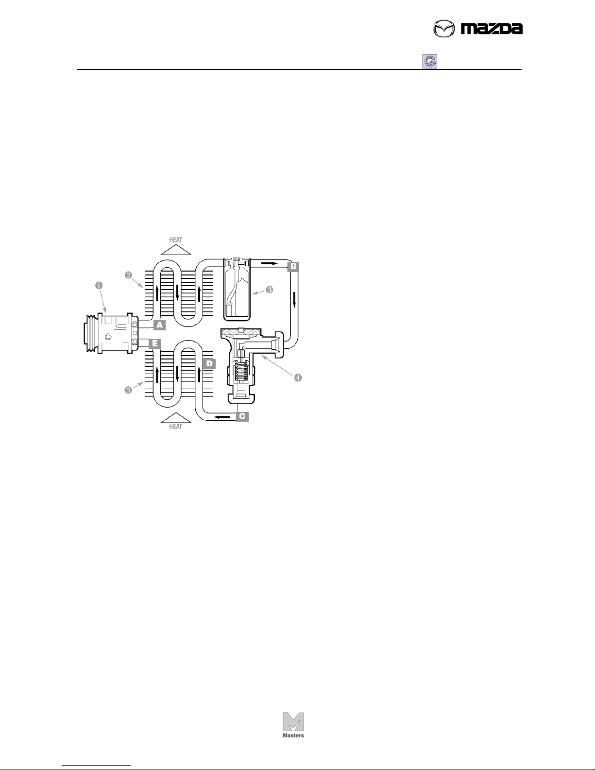
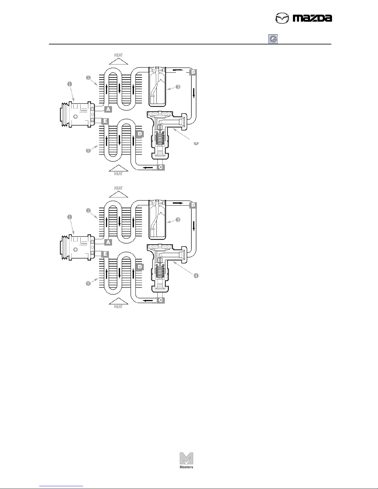
2. Technician A says that at point E in
this illustration the refrigerant is high
pressure vapor.
Technician B says at point E in this
illustration the refrigerant is a low
pressure vapor.
Who is correct?
a. Technician A
b. Technician B
c. Both Technicians
d. Neither technician
3. One BTU is the amount of heat needed at sea level to raise the temperature of
one pound of water;
a. One degree Centigrade
b. Ten degrees Centigrade
c. Ten degrees Fahrenheit
d. One degree Fahrenheit
4. Technician A says the latent heat applied to change a substance from a liquid to a
vapor is called the latent heat of vaporization.
Technician B says the latent heat applied to change a substance from a liquid to a
vapor is called the latent heat of condensation.
a. Technician A
b. Technician B
c. Both Technicians
d. Neither technician

AIR CONDITIONING
SG00b - Pre-Test
SG00b-2
-
-
5. Technician A says in a Mazda A/C system the refrigerant changes state from a
liquid to a vapor in the compressor while losing heat.
Technician B says the compressor acts as a pump for the refrigerant in an A/C
system.
Who is correct?
a. Technician A
b. Technician B
c. Both Technicians
d. Neither technician
6. Technician A says the compressor increases the temperature of the vaporized
refrigerant without adding heat.
Technician B says the compressor raises the pressure of the vaporized refrigerant
and not the temperature.
Who is correct?
a. Technician A
b. Technician B
c. Both Technicians
d. Neither technician
7. Which component in this
illustration receives hot, high
pressure refrigerant gas from the
compressor and transfers the heat to
the outside air.
a. 2
b. 3
c. 4
d. 5
8. Technician A says the expansion valve or orifice tube controls the amount of
refrigerant entering the evaporator.
Technician B says the accumulator regulates the refrigerant flow to the evaporator.
Who is correct?
a. Technician A
b. Technician B
c. Both Technicians
d. Neither technician
AIR CONDITIONING
SG00b - Pre-Test
SG00b-3
-
-
9. Which component in this
illustration removes heat from the
passenger compartment and
transfers it to the refrigerant?
a. 2
b. 3
c. 4
d. 5
10. At point A the refrigerant is;
a. High pressure liquid
b. High pressure vapor
c. Low pressure liquid
d. Low pressure vapor
11. Technician A says R-12 and R-134a system have different-sized service valves,
to prevent accidental mixing of refrigerants.
Technician B says R-134a systems use larger, metric-thread, quick connect service
valves.
Who is correct?
a. Technician A
b. Technician B
c. Both Technicians
d. Neither technician
123
4
5

AIR CONDITIONING
SG00b - Pre-Test
SG00b-4
-
-
12. Technician A says do not expose refrigerant to open flame. R-12 may produce
poisonous phosgene gas, and R-134a may support combustion.
Technician B says a propane torch style leak detector is the best type of detector for
R-12 and R134a systems.
Who is correct?
a. Technician A
b. Technician B
c. Both Technicians
d. Neither technician
13. Technician A says if refrigeration oil is not sealed properly, it will absorb moisture
from the air.
Technician B says you can reuse refrigeration oil removed from an operating A/C
system.
Who is correct?
a. Technician A
b. Technician B
c. Both Technicians
a. Neither technician
14. Technician A says after repairs have been performed, or if a system has been
open for a long period of time, the system must be evacuated to remove moisture
and ensure that it will hold a vacuum.
Technician B says the minimum time any system should be evacuated is 15 minutes.
The longer the system has been open, the longer it should be evacuated.
Who is correct?
a. Technician A
b. Technician B
c. Both Technicians
d. Neither technician
15. Technician A says all refrigerant should be recovered and recycled.
Technician B says only R-12 needs to be recovered and recycled.
Who is correct?
a. Technician A
b. Technician B
c. Both Technicians
d. Neither technician
AIR CONDITIONING
SG00b - Pre-Test
SG00b-5
-
-
16. Technician A says the accumulator traps liquid refrigerant allowing it time to
completely vaporize.
Technician B says if liquid refrigerant reaches the compressor it could be damaged.
Who is correct?
a. Technician A
b. Technician B
c. Both Technicians
d. Neither technician
17. Technician A says small refrigerant leaks are normal and the refrigerant should
be replaced once a year as a maintenance item.
Technician B says if the refrigerant has leaked out of an A/C system the technician
should charge the system with a small amount of refrigerant for leak testing purposes.
Who is correct?
a. Technician A
b. Technician B
c. Both Technicians
d. Neither technician
18. This method of charging an A/C system adds gaseous refrigerant through the
low-side service valve while the compressor is running.
a. Liquid charging
b. Vapor charging
c. Both answers a and b
d. Neither answer a or b
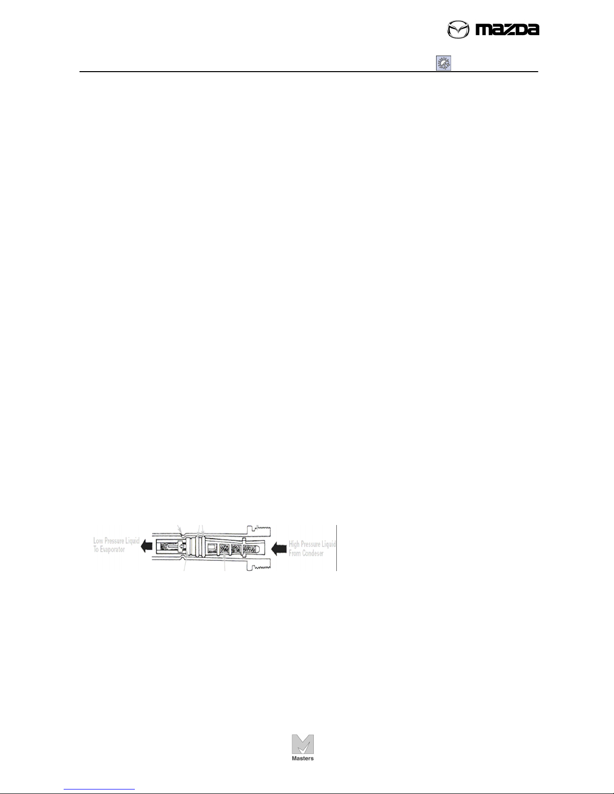
19. The component in this illustration divides the A/C system into high and low
pressure sides, what is it?
a. Fixed orifice tube
b. Expansion valve
c. Accumulator
d. Receiver dryer
AIR CONDITIONING
SG00b - Pre-Test
SG00b-6
-
-
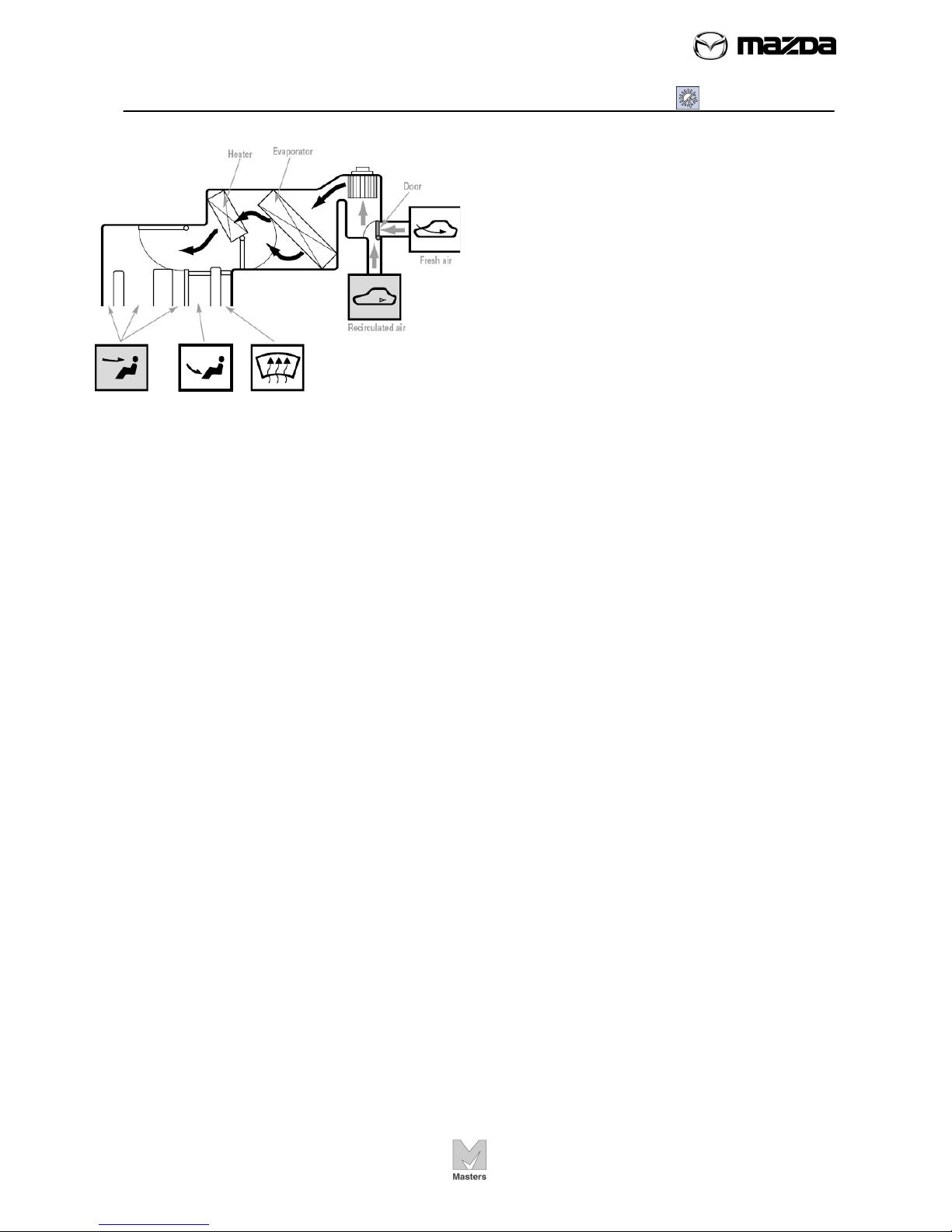
20. Which statement is true about this
climate control plenum assembly?
a. All air passes through the
evaporator
b. The air is being re-circulated
c. The temperature blend door is set
for max heat
d. All the above

AIR CONDITIONING
SG01 - Basic System
SG01-1
-
-
OBJECTIVES
After completing this section, you will be able to:
Describe a refrigeration cycle and what part the components play in the
cooling process.
Identify major components of a manual A/C system
Activities To complete this section, you will perform the following activities:
Activity Title/Description Location
AC01 Identifying A/C Components Shop
AC02 Locating A/C Protection Devices Shop
AC03 A/C performance Check Shop
AC04 Refrigerant Charging Shop
In this section:
Basic System
A/C Components ........................................................................................... 2
A/C Unit construction/operation ..................................................................... 3
Evaporator ..................................................................................................... 4
Expansion valve ............................................................................................ 4
Air Mix Door Operation .................................................................................. 5
Airflow Mode Door Operation ........................................................................ 5
Air filter function ............................................................................................. 6
A/C compressor ............................................................................................. 6
Condenser ..................................................................................................... 7
Refrigerant life ............................................................................................... 7
Spring-lock Coupling ..................................................................................... 8
Gauge manifold reading ................................................................................ 9
Refrigerant System Service Warnings (Reference) ....................................... 10
Refrigerant System Service Cautions ............................................................ 10
AC abbreviation ............................................................................................. 12
Item Specification .......................................................................................... 12
Review Exercise ............................................................................................ 13
NOTE
This SG: Student Guide is developed based on Mazda 3.
AIR CONDITIONING
SG01 - Basic System
SG01-2
-
-
A/C Components
Name the components.
AIR CONDITIONING
SG01 - Basic System
SG01-3
-
-
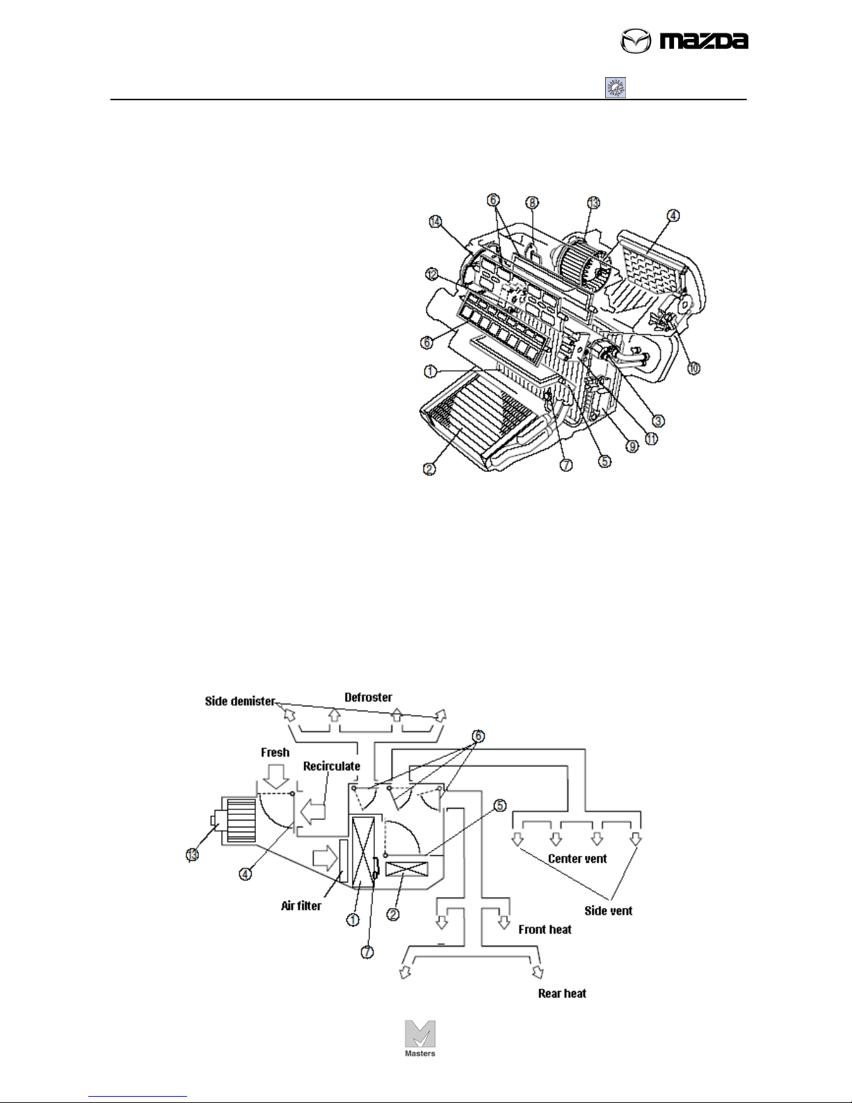
A/C unit construction/operation
• The figure below shows A/C unit which integrates the blower, cooling and heater
units.
1. Evaporator*
2. Heater core*
3. Expansion valve
4. Air intake door*
5. Air mix door*
6. Airflow mode door*
7. Evaporator temperature
sensor*
8. Resistor (manual air conditioner)
9. Power MOS FET (full-auto air conditioner)
10. Air intake actuator
11. Air mix actuator (full-auto air conditioner)
12. Airflow mode actuator (full-auto air conditioner)
13. Blower motor*
14. Airflow mode main link
* Also refer to the figure below “Ventilation System”
Ventilation System
AIR CONDITIONING
SG01 - Basic System
SG01-4
-
-
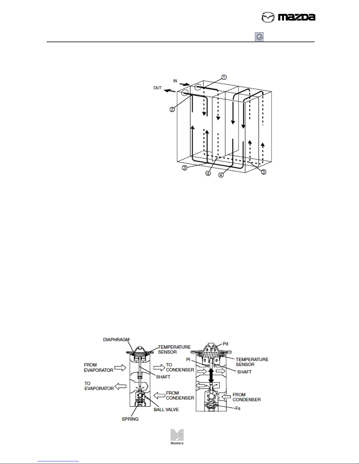
Evaporator
• The figure below shows a double-tank drawn cup.
1. Separation part
2. Rejoining point
3. Separation part
4. Rejoining point
Expansion valve
• The liquid refrigerant of about 1.5 MPa is sprayed at the expansion valve. The
splayed refrigerant is, then, expanded its volume that causes its pressure decreased
to about 0.2 MPa. This makes the refrigerant to be vaporized causing reduction of
temperature. The expansion valve regulates the flow volume of the refrigerant.
• The amount of refrigerant delivered to the evaporator is adjusted by the opening
angle of the ball valve in the expansion valve.
• Opening angle is adjusted by a balance of the R-134a pressure (Pd) in the
diaphragm, and a composite force of evaporator discharge pressure (PI) against the
lower part of the diaphragm and spring force (Fs) pushing up the ball valve. When
PI increases, the temperature of the temperature sensor near the diaphragm rises
and the Pd heated by the R-134a in the diaphragm increases. When the Pd
increases more than PI + Fs, the diaphragm is pushed down, and the shaft attached
to end of the temperature sensor rod pushes down the ball valve, increasing the
amount of liquid refrigerant flow. When the evaporator discharge refrigerant
temperature decreases, PI + Fs increases more than Pd, the ball valve is pushed
up, and the amount of liquid refrigerant flow decreases.
AIR CONDITIONING
SG01 - Basic System
SG01-5
-
-
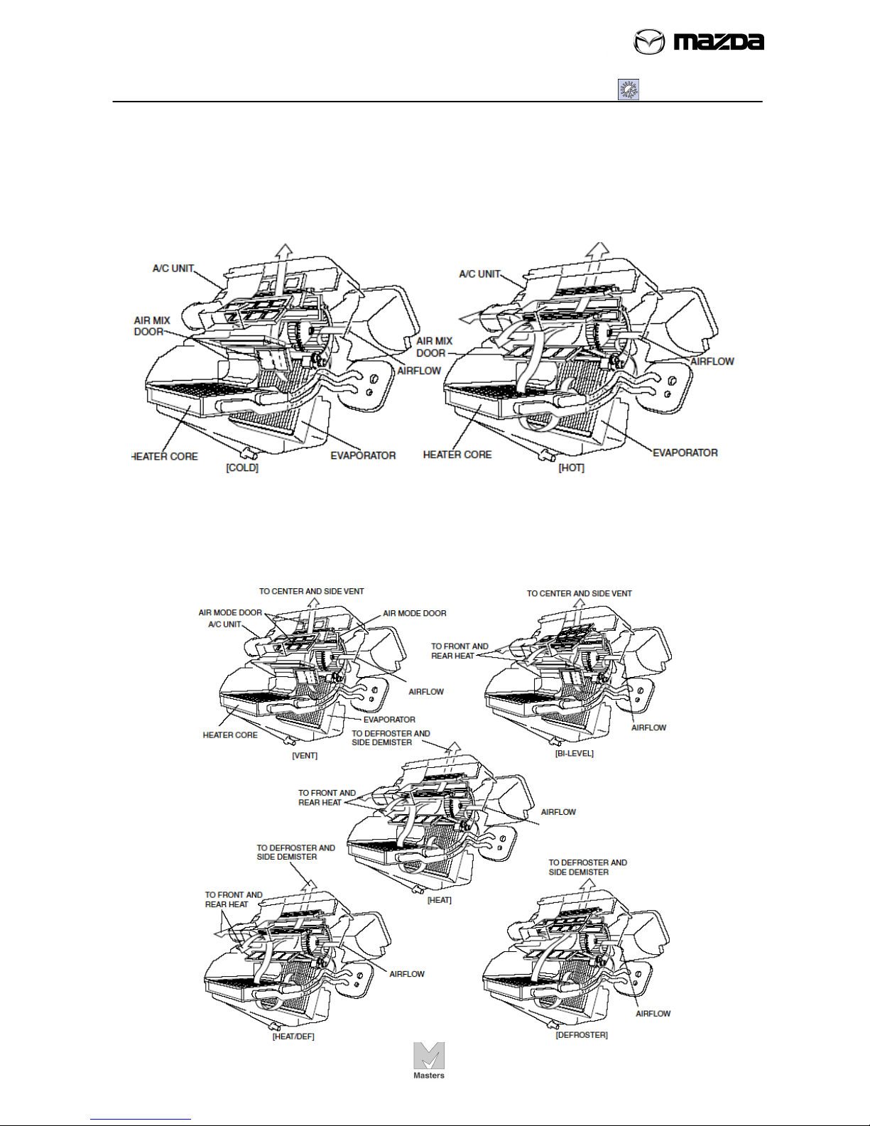
Air Mix Door Operation
• The air mix door, installed in the A/C unit, controls HOT or COLD position,
depending on the position of the temperature control dial. As a result, airflow
distribution changes, and the airflow temperature is controlled.
Airflow Mode Door Operation
• The airflow mode doors move to VENT, BI-LEVEL, HEAT, HEAT/DEF, or
DEFROSTER position, depending on the position of the airflow mode selector dial.
AIR CONDITIONING
SG01 - Basic System
SG01-6
-
-
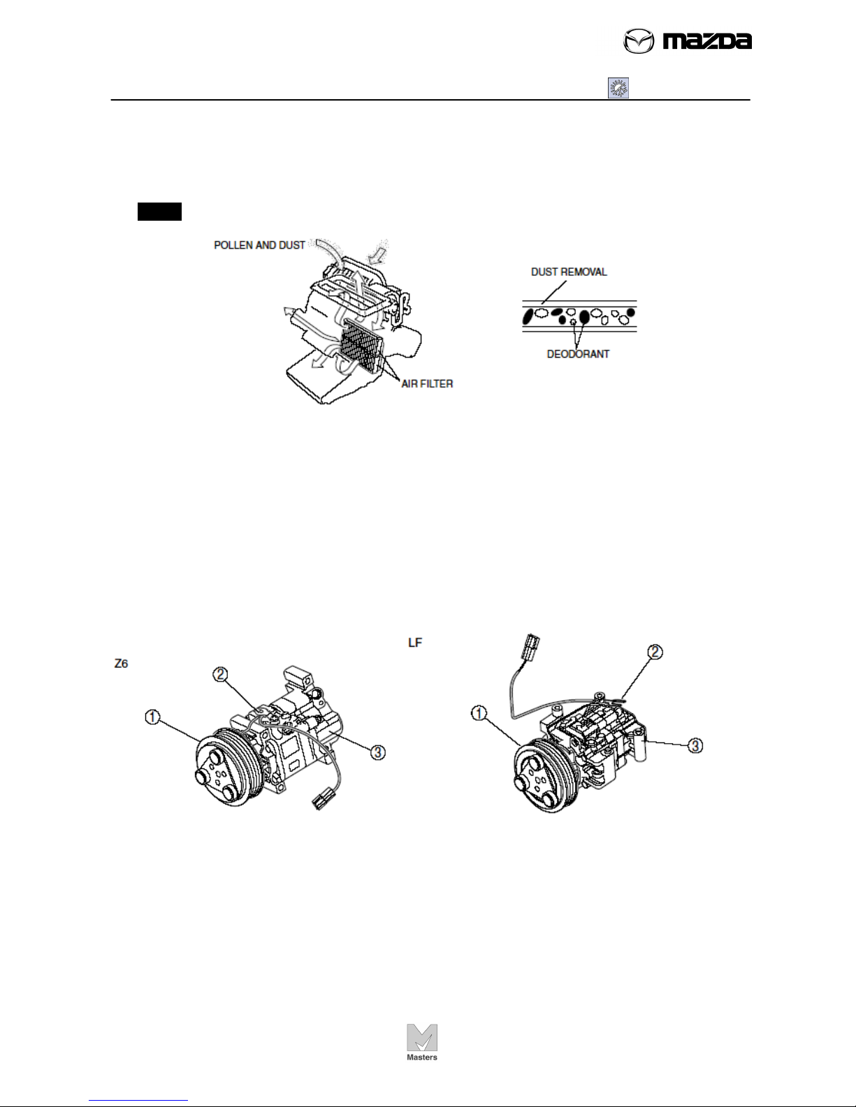
Air filter function
• The figure below shows air filter that can remove pollen and dust has been added.
• The air filter cannot be reused and must be replaced periodically.
NOTE Even new air filters are gray; be careful not to mistake the gray color as dirt.
A/C compressor
• A rotary-vane type (H12A1) A/C compressor body has been adopted for size,
weight, and operation vibration reduction.
1. Magnetic clutch
2. Thermal protector
3. A/C compressor
AIR CONDITIONING
SG01 - Basic System
SG01-7
-
-
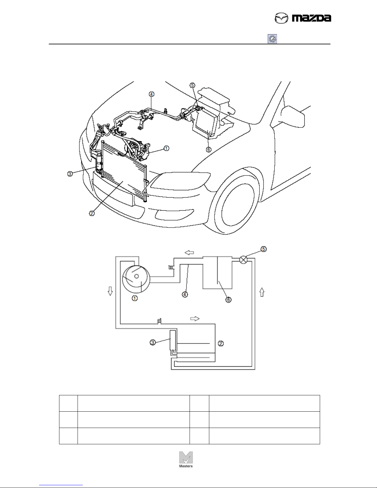
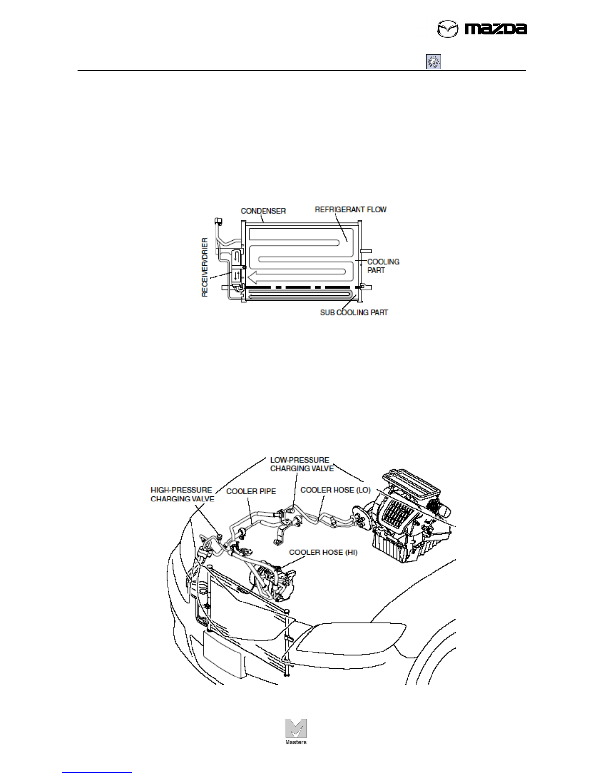
Condenser
• The figure below shows a sub cool condenser. It is a multi-flow condenser which is
equipped with a sub cooling part and integrated with a receiver/drier.
• The sub cool condenser separates liquid-gas refrigerant initially cooled at the
condenser via the receiver/drier, where it returns again to the condenser sub cooling
part and is cooled, accelerating liquefaction and improving cooling capacity.
Refrigerant life
• The pipes in the refrigerant lines are made of aluminum alloy and the hoses are
made of rubber (flexible hose).
• A high-pressure charging valve is located on the cooler hose (HI) and a lowpressure charging valve is located on the cooler hose (LO).
Z6
AIR CONDITIONING
SG01 - Basic System
SG01-8
-
-
LF
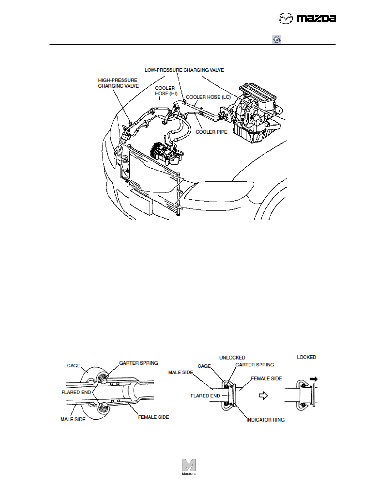
Spring-lock Coupling
• Spring-lock coupling is used for pipe-to-pipe connections. As a result, pipes can be
connected easily, maintenance of torque is unnecessary, and serviceability is
improved.
• There is a garter spring in the cage on the male side (cooler pipe or cooler hose
(LO)) of spring-lock coupling type and the end of the pipe on the female side (A/C
unit) is flared. When the pipes are being connected, the flared end of the female
side forces the garter spring on the female side to expand, and by fully inserting the
male side into the female side, the flared end is locked by the garter spring. When
the cooler pipe or cooler hose (LO) is replaced, the additional indicator ring comes
out after connecting; indicating that the flared end is locked.
AIR CONDITIONING
SG01 - Basic System
SG01-9
-
-
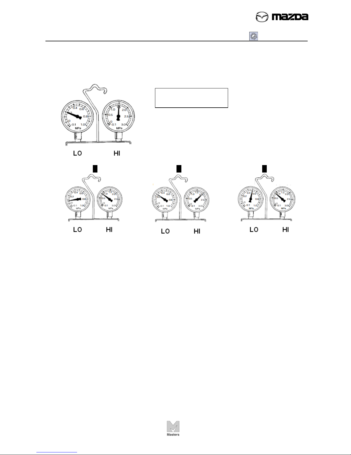
Gauge manifold reading
Normal
LO: 0.15 – 0.25 MPa
HI: 1.37 – 1.57 MPa
It may vary under the different condition.
A B C
A: Insufficient refrigerant
B: Excessive refrigerant or insufficient cooling
C: Compressor failure

AIR CONDITIONING
SG01 - Basic System
SG01-10
-
-
Refrigerant System Service Warnings (Reference)
Handling Refrigerant
• Avoid breathing air conditioning refrigerant or lubricant vapor. Exposure may irritate
eyes, nose and throat. Also, due to environmental concerns, we urge use of
recovery/recycling/recharging equipment when draining R-134a from the air
conditioning system. If accidental system discharge occurs, ventilate work area
before resuming service.
• Do not perform pressure test or leak test for R-134a service equipment and/or
vehicle air conditioning system using compressed air. Some mixtures of air and R134a have been shown to be combustible at elevated pressures. These mixtures, if
ignited, may cause injury or property damage. Additional health and safety
information may be obtained from refrigerant manufacturers.
• Do not allow the refrigerant to leak near fire or any kind of heat. A poisonous gas
may be generated if the refrigerant gas contacts fire or heat such as from cigarettes
and heaters. When carrying out any operation that can cause refrigerant leakage,
extinguish or remove the above-mentioned heat sources and maintain adequate
ventilation.
• Handling liquid refrigerant is dangerous. A drop of it on the skin can result in
localized frostbite. When handling the refrigerant, wear gloves and safety goggles. If
refrigerant splashes into the eyes, immediately wash them with clean water and
consult a doctor.
Storing Refrigerant
• The refrigerant container is highly pressurized. If it is subjected to high heat, it could
explode, scattering metal fragments and liquid refrigerant that can seriously injure
you. Store the refrigerant at temperatures below 40 °C {104 °F}.
Refrigerant System Service Cautions
Handling Insufficient Refrigerant Level
• If an insufficient refrigerant level is detected at troubleshooting, do not charge (add)
the refrigerant. Because an accurate amount of refrigerant cannot be determined
from the pressure indicated on the manifold gauge, never charge the refrigerant. If
there is too much or too little refrigerant from the refilling, there may be secondary
problems such as damage to the refrigerant cycle parts, or a decrease of cooling
performance. Therefore, if it is determined that the refrigerant level is insufficient,
completely remove refrigerant from the refrigerant cycle and refill with refrigerant to
the specified amount.
AIR CONDITIONING
SG01 - Basic System
SG01-11
-
-
Handling Compressor Oil
• Use only ATMOS GU10 compressor oil for this vehicle. Using a PAG oil other than
ATMOS GU10 compressor oil can damage the A/C compressor.
• Do not spill ATMOS GU10 compressor oil on the vehicle. A drop of compressor oil
on the vehicle surface can eat away at the paint. If oil gets on the vehicle, wipe it off
immediately.
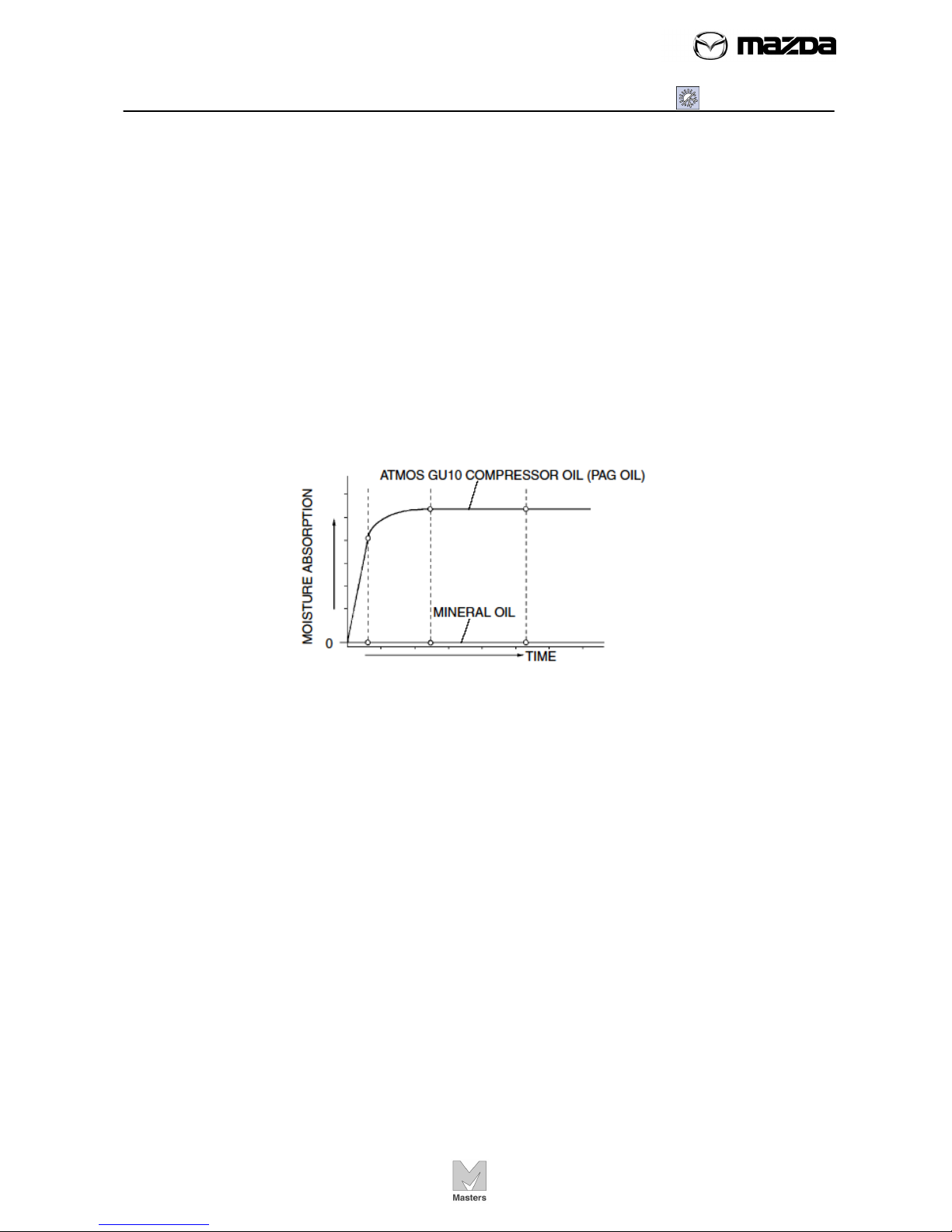
• ATMOS GU10 compressor oil (PAG oil) has higher moisture absorption efficiency
than the previously used mineral oil. If moisture mixes with the compressor oil, the
refrigerant system could be damaged. Therefore, install caps immediately after
using the compressor oil or removing refrigerant system parts to prevent moisture
absorption.
Moisture Absorption
0
• If the refrigerant gas is completely discharged from the system for reasons such as
a malfunction during A/C operation, repair or replace the malfunctioning part, charge
the refrigerant to the specified amount and always add 60 ml {60 cc, 2.03 fl oz} of
compressor. If the compressor oil is not adequately replenished, the A/C
compressor may quickly deteriorate, abnormal noise may develop, cooling
performance may be affected or, in the worst case, the A/C compressor may seize.

AIR CONDITIONING
SG01 - Basic System
SG01-12
-
-
HVAC ABBREVIATION
A/C: Air Conditioning
B+: Battery Positive Voltage
CAN: Control Area Network
CPU: Central Processing Unit
HI: High
IG: Ignition
ISO: International Organization for Standardization
LO: Low
M: Motor
MAX: Maximum
OFF: Switch Off
ON: Switch On
PCM: Powertrain Control Module
REC: Recirculate
SW: Switch
Item Specification (Mazda 3)
Heating capacity (kW {kcal/h}): 4.550 {3,913}
Cooling capacity (kW {kcal/h}): 3.960 {3,406}
Refrigerant
Type: R-134a
Regular amount: (approx. quantity) (g {oz}) 525 {18.5}
A/C compressor
Type: Vane-rotary
Discharge capacity (ml {cc, fl oz}): 120 {120, 4.06}
Max. allowable speed (rpm): 6,400/Z6, 7,200/LF
Lube oil
Type: ATMOS GU10
Sealed volume (approx. quantity) (ml {cc, fl oz}): 120 {120, 4.06}/Z6,
150 {150, 5.07}: LF
Condenser
Type: Multi-flow (sub-cooling type)
Radiated heat (kW {kcal/h}): 6.600 {5,680}
Receiver/drier capacity (ml {cc, fl oz}): 180 {180, 6.08}
Desiccant: Synthetic zeolite
Expansion valve type: Block type
Evaporator type: Double-tank drawn cup
Temperature control: Reheat full air mix type
 Loading...