

Mazda 3 2007, 6 2007, SPEED6 2007, MX-5 2007, RX-8 2007 Service Manual
...
2007
Mazda3
MAZDASPEED3
Mazda5
Mazda6
MAZDASPEED6
Mazda MX-5
Mazda RX-8
Service
Highlights
FOREWORD
This manual explains components, system
operations and functions for the Mazda3,
MAZDASPEED3, Mazda5, Mazda6,
MAZDASPEED6, Mazda MX-5,
Mazda RX-8.
Mazda3
MAZDASPEED3
Mazda5
Mazda6
MAZDASPEED6
For proper repair and maintenance, a
thorough familiarization with this manual is
important, and it should always be kept in a
handy place for quick and easy reference.
All the contents of this manual, including
drawings and specifications, are the latest
available at the time of printing.
As modifications affecting repair or
maintenance occur, relevant information
supplementary to this volume will be made
available at Mazda dealers.
This manual should be kept up-to-date.
Mazda Motor Corporation reserves the right
to alter the specifications and contents of
this manual without obligation or advance
notice.
All rights reserved. No part of this book may
be reproduced or used in any form or by
any means, electronic or mechanical—
including photocopying and recording and
the use of any kind of information storage
and retrieval system—without permission in
writing.
Mazda MX-5
Mazda RX-8
© 2006 Mazda Motor Corporation
PRINTED IN U.S.A., JULY 2006
Form No. 3422–1U–06G
Part No. 9999–95–MODL–07
Mazda Motor Corporation
HIROSHIMA, JAPAN
APPLICATION:
This manual is applicable to vehicles
beginning with the Vehicle Identification
Numbers (VIN),and related materials shown
on the following page.
Mazda MX-5
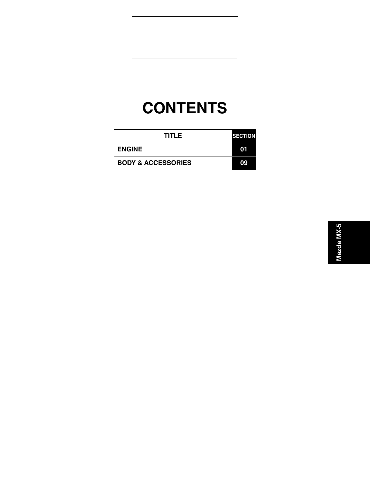
CONTENTS
TITLE
ENGINE 01
BODY & ACCESSORIES
SECTION
09
Mazda MX-5


2007 Mazda3, MAZDASPEED3, Mazda5, Mazda6, MAZDASPEED6, Mazda MX-5,
Mazda RX-8 Service Highlights (3422–1U–06G)
ENGINE
Toc of S C T
OUTLINE[LF] . . . . . . . . . . . . . . 01-00 ON-BOARD DIAGNOSTIC
[LF]. . . . . . . . . . . . . . . . . . . . . 01-02
CONTROL SYSTEM[LF] . . . . . 01-40
Toc of S C T
01-00 OUTLINE [LF]
ENGINE ABBREVIATIONS[LF] . . . . . . . . 01-00–1
ENGINE FEATURES[LF] . . . . . . . . . . . . . 01-00–1
On-board Diagnostic . . . . . . . . . . . . . . . 01-00–1
End of Toc
NG: ENGINE COMPLETE
ENGINE ABBREVIATIONS[LF]
ABS Antilock Brake System
AT Automatic Transmission
ATDC After Top Dead Center
BTDC Before Top Dead Center
CAN Controller Area Network
CCM Comprehensive Component Monitor
CM Control Module
DC Drive Cycle
DSC Dynamic Stability Control
EX Exhaust
HU Hydraulic Unit
IN Intake
KOEO Key On Engine Off
KOER Key On Engine Running
MT Manual Transmission
OCV Oil Control Valve
PCV Positive Crankcase Ventilation
PID Parameter Identification
RAM Random Access Memory
ENGINE SPECIFICATION[LF] . . . . . . . . 01-00–2
Specification. . . . . . . . . . . . . . . . . . . . . 01-00–2
01
SECTION
id0100e1100100
Mazda MX-5
End Of Sie
ENGINE FEATURES[LF]
On-board Diagnostic
To meet OBD-II regulations • Mode 03 of diagnostic test modes changed
Improved serviceability • Mode 01, 06, and 08 of diagnostic test modes changed
End Of Sie
id0100e1100200
01-00–1
2007 Mazda3, MAZDASPEED3, Mazda5, Mazda6, MAZDASPEED6, Mazda MX-5,
Mazda RX-8 Service Highlights (3422–1U–06G)
OUTLINE [LF]
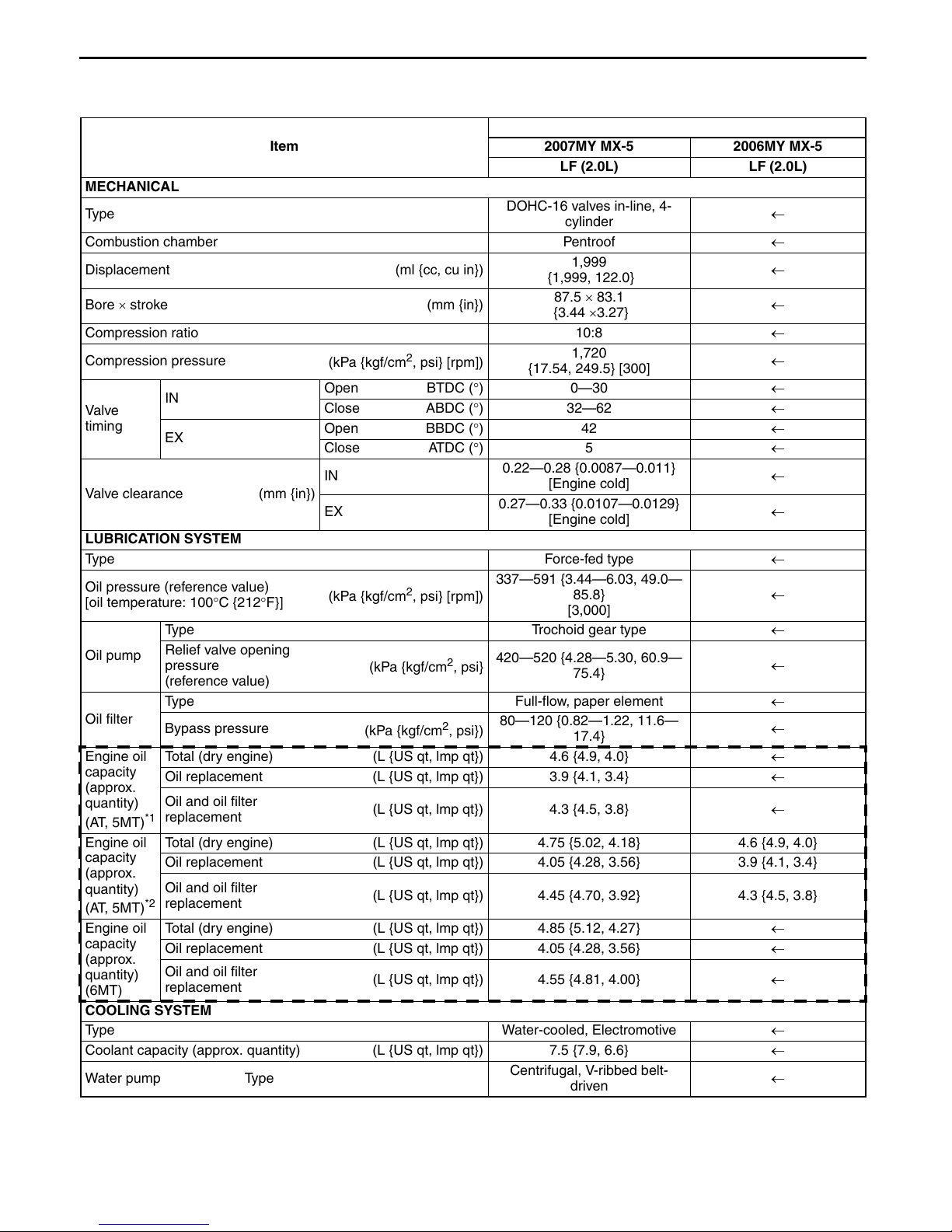
ENGINE SPECIFICATION[LF]
Specification
Specification
Item
MECHANICAL
Ty pe
Combustion chamber Pentroof ←
Displacement (ml {cc, cu in})
Bore × stroke (mm {in})
Compression ratio 10:8 ←
Compression pressure
Val ve
timing
IN
EX
(kPa {kgf/cm
Open BTDC (°) 0—30 ←
Close ABDC (°)32—62 ←
Open BBDC (°)42 ←
Close ATDC (°)5 ←
2
, psi} [rpm])
IN
Valve clearance (mm {in})
EX
LUBRICATION SYSTEM
Type Force-fed type ←
Oil pressure (reference value)
[oil temperature: 100°C {212°F}]
(kPa {kgf/cm
2
, psi} [rpm])
337—591 {3.44—6.03, 49.0—
Type Trochoid gear type ←
Oil pump
Relief valve opening
pressure
(kPa {kgf/cm
2
, psi}
420—520 {4.28—5.30, 60.9—
(reference value)
Type Full-flow, paper element ←
Oil filter
Engine oil
capacity
(approx.
quantity)
(AT, 5MT)
Engine oil
capacity
(approx.
quantity)
(AT, 5MT)
Engine oil
capacity
(approx.
quantity)
(6MT)
Bypass pressure
(kPa {kgf/cm
Total (dry engine) (L {US qt, lmp qt}) 4.6 {4.9, 4.0} ←
Oil replacement (L {US qt, lmp qt}) 3.9 {4.1, 3.4} ←
Oil and oil filter
*1
replacement
(L {US qt, lmp qt}) 4.3 {4.5, 3.8} ←
Total (dry engine) (L {US qt, lmp qt}) 4.75 {5.02, 4.18} 4.6 {4.9, 4.0}
Oil replacement (L {US qt, lmp qt}) 4.05 {4.28, 3.56} 3.9 {4.1, 3.4}
Oil and oil filter
*2
replacement
(L {US qt, lmp qt}) 4.45 {4.70, 3.92} 4.3 {4.5, 3.8}
Total (dry engine) (L {US qt, lmp qt}) 4.85 {5.12, 4.27} ←
Oil replacement (L {US qt, lmp qt}) 4.05 {4.28, 3.56} ←
Oil and oil filter
replacement
(L {US qt, lmp qt}) 4.55 {4.81, 4.00} ←
2
, psi})
COOLING SYSTEM
Type Water-cooled, Electromotive ←
Coolant capacity (approx. quantity) (L {US qt, lmp qt}) 7.5 {7.9, 6.6} ←
Water pump Type
2007MY MX-5 2006MY MX-5
LF (2.0L) LF (2.0L)
DOHC-16 valves in-line, 4-
cylinder
1,999
{1,999, 122.0}
87.5 × 83.1
{3.44 ×3.27}
1,720
{17.54, 249.5} [300]
0.22—0.28 {0.0087—0.011}
[Engine cold]
0.27—0.33 {0.0107—0.0129}
[Engine cold]
85.8}
[3,000]
75.4}
80—120 {0.82—1.22, 11.6—
17.4}
Centrifugal, V-ribbed belt-
driven
id0100e1100300
←
←
←
←
←
←
←
←
←
←
01-00–2
Revised 12/2006 (Ref. No. R223/06)
2007 Mazda3, MAZDASPEED3, Mazda5, Mazda6, MAZDASPEED6, Mazda MX-5,
Mazda RX-8 Service Highlights (3422–1U–06G)
OUTLINE [LF]
Specification
Item
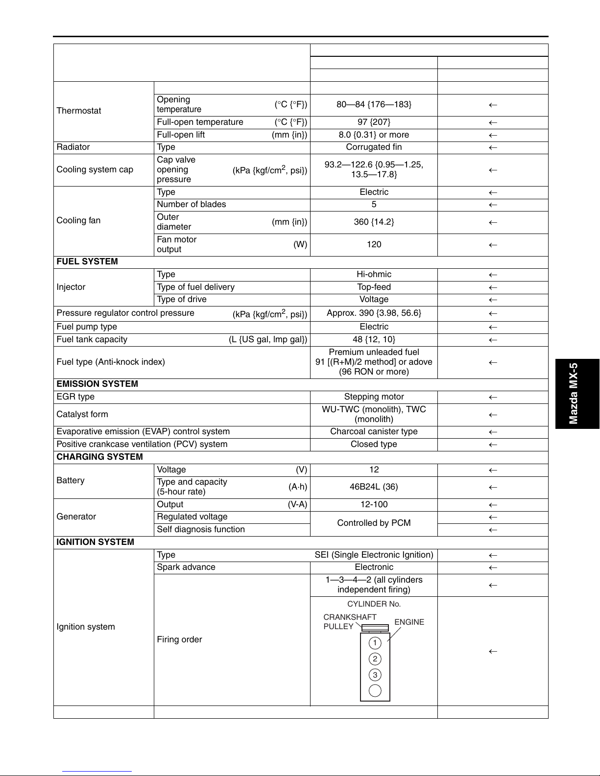
Type Wax, bottom-bypass ←
Opening
Thermostat
Radiator Type Corrugated fin ←
Cooling system cap
Cooling fan
FUEL SYSTEM
Injector
Pressure regulator control pressure
Fuel pump type Electric ←
Fuel tank capacity (L {US gal, lmp gal}) 48 {12, 10} ←
Fuel type (Anti-knock index)
EMISSION SYSTEM
EGR type Stepping motor ←
Catalyst form
Evaporative emission (EVAP) control system Charcoal canister type ←
Positive crankcase ventilation (PCV) system Closed type ←
CHARGING SYSTEM
Battery
Generator
IGNITION SYSTEM
Ignition system
temperature
Full-open temperature (°C {°F}) 97 {207} ←
Full-open lift (mm {in}) 8.0 {0.31} or more ←
Cap valve
opening
pressure
Type Electric ←
Number of blades 5 ←
Outer
diameter
Fan mo tor
output
Type Hi-ohmic ←
Type of fuel delivery Top-feed ←
Type of drive Voltage ←
Voltage (V) 12 ←
Type and capacity
(5-hour rate)
Output (V-A) 12-100 ←
Regulated voltage
Self diagnosis function ←
Type SEI (Single Electronic Ignition) ←
Spark advance Electronic ←
Firing order
(kPa {kgf/cm2, psi})
(kPa {kgf/cm
(°C {°F}) 80—84 {176—183} ←
(mm {in}) 360 {14.2} ←
(W) 120 ←
2
, psi})
91 [(R+M)/2 method] or adove
(A·h) 46B24L (36) ←
2007MY MX-5 2006MY MX-5
LF (2.0L) LF (2.0L)
93.2—122.6 {0.95—1.25,
13.5—17.8}
Approx. 390 {3.98, 56.6} ←
Premium unleaded fuel
(96 RON or more)
WU-TWC (monolith), TWC
CRANKSHAFT
PULLEY
(monolith)
Controlled by PCM
1—3—4—2 (all cylinders
independent firing)
CYLINDER No.
ENGINE
1
2
3
4
←
←
←
←
←
←
Mazda MX-5
Spark plug Type L3G2 18 110, L3Y1 18 110 ←
01-00–3
2007 Mazda3, MAZDASPEED3, Mazda5, Mazda6, MAZDASPEED6, Mazda MX-5,
SM
Item
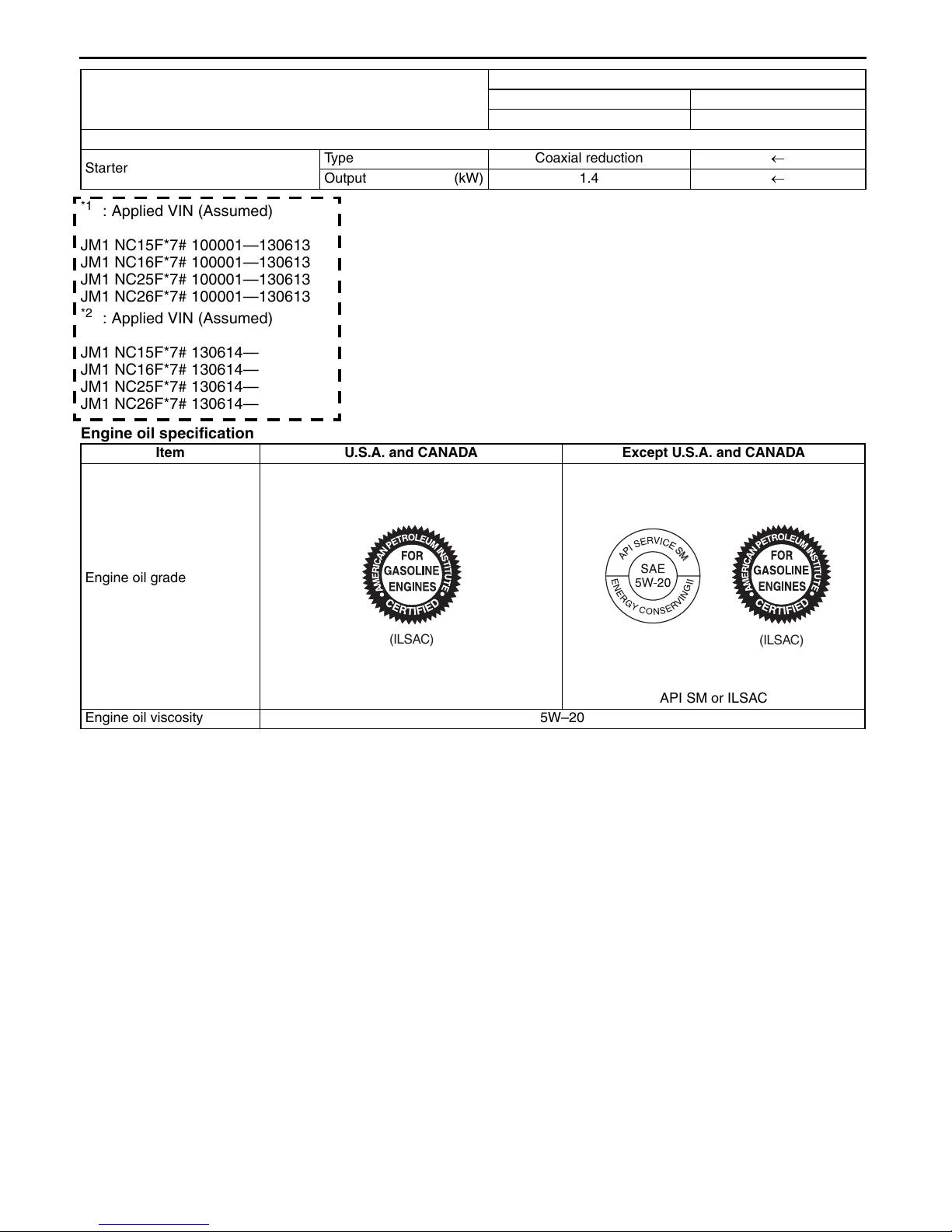
STARTING SYSTEM
Starter
*1
: Applied VIN (Assumed)
JM1 NC15F*7# 100001—130613
JM1 NC16F*7# 100001—130613
JM1 NC25F*7# 100001—130613
JM1 NC26F*7# 100001—130613
*2
: Applied VIN (Assumed)
JM1 NC15F*7# 130614—
JM1 NC16F*7# 130614—
JM1 NC25F*7# 130614—
JM1 NC26F*7# 130614—
Engine oil specification
Item U.S.A. and CANADA Except U.S.A. and CANADA
Mazda RX-8 Service Highlights (3422–1U–06G)
OUTLINE [LF]
Specification
2007MY MX-5 2006MY MX-5
LF (2.0L) LF (2.0L)
Type Coaxial reduction ←
Output (kW) 1.4 ←
Engine oil grade
(ILSAC)
Engine oil viscosity 5W–20
End Of Sie
SM
(ILSAC)
API SM or ILSAC
01-00–4
Revised 12/2006 (Ref. No. R223/06)
ON-BOARD DIAGNOSTIC [LF]
01-02 ON-BOARD DIAGNOSTIC [LF]
DIAGNOSTIC TEST MODE[LF] . . . . . . . 01-02–1
Sending Diagnostic Data . . . . . . . . . . . 01-02–2
Sending Freeze Frame Data . . . . . . . . 01-02–3
Sending Emission-related
Malfunction Code . . . . . . . . . . . . . . . . 01-02–4
Sending Intermittent Monitoring
System Test Results . . . . . . . . . . . . . 01-02–7
Sending Continuous Monitoring
System Test Results . . . . . . . . . . . . . 01-02–7
DLC-2 Outline . . . . . . . . . . . . . . . . . . . 01-02–8
DTC DETECTION LOGIC AND
CONDITIONS[LF] . . . . . . . . . . . . . . . . . . 01-02–8
KOEO/KOER SELF-TEST[LF] . . . . . . . . . 01-02–17
KOEO (Key ON, Engine Off)
Self-test. . . . . . . . . . . . . . . . . . . . . . . . 01-02–17
KOER (Key ON, Engine Running)
Self-test. . . . . . . . . . . . . . . . . . . . . . . . 01-02–17
PID/DATA MONITOR AND
RECORD[LF] . . . . . . . . . . . . . . . . . . . . . 01-02–20
SIMULATION TEST[LF] . . . . . . . . . . . . . . 01-02–23
End of Toc
NG: ON-BOARD DIAGNOSTIC (ENGINE CONTROL SYSTEM)
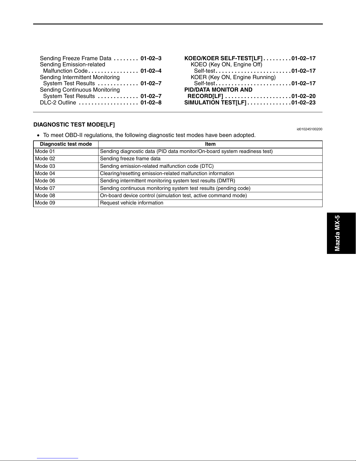
DIAGNOSTIC TEST MODE[LF]
• To meet OBD-II regulations, the following diagnostic test modes have been adopted.
Diagnostic test mode Item
Mode 01 Sending diagnostic data (PID data monitor/On-board system readiness test)
Mode 02 Sending freeze frame data
Mode 03 Sending emission-related malfunction code (DTC)
Mode 04 Clearing/resetting emission-related malfunction information
Mode 06 Sending intermittent monitoring system test results (DMTR)
Mode 07 Sending continuous monitoring system test results (pending code)
Mode 08 On-board device control (simulation test, active command mode)
Mode 09 Request vehicle information
id010245100200
Mazda MX-5
01-02–1
ON-BOARD DIAGNOSTIC [LF]
Sending Diagnostic Data
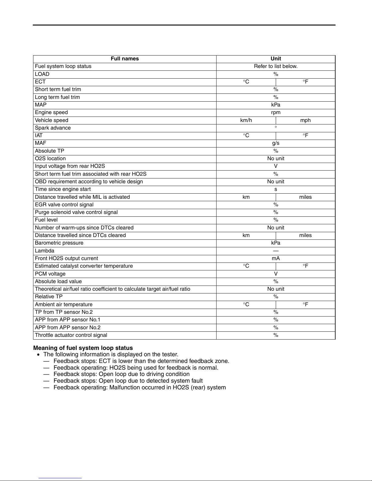
PID data monitor
• The PID data monitor items are shown below.
PID data monitor table
Full names Unit
Fuel system loop status Refer to list below.
LOAD %
ECT °C °F
Short term fuel trim %
Long term fuel trim %
MAP kPa
Engine speed rpm
Vehicle speed km/h mph
Spark advance °
IAT °C °F
MAF g/s
Absolute TP %
O2S location No unit
Input voltage from rear HO2S V
Short term fuel trim associated with rear HO2S %
OBD requirement according to vehicle design No unit
Time since engine start s
Distance travelled while MIL is activated km miles
EGR valve control signal %
Purge solenoid valve control signal %
Fuel level %
Number of warm-ups since DTCs cleared No unit
Distance travelled since DTCs cleared km miles
Barometric pressure kPa
Lambda —
Front HO2S output current mA
Estimated catalyst converter temperature °C °F
PCM voltage V
Absolute load value %
Theoretical air/fuel ratio coefficient to calculate target air/fuel ratio No unit
Relative TP %
Ambient air temperature °C °F
TP from TP sensor No.2 %
APP from APP sensor No.1 %
APP from APP sensor No.2 %
Throttle actuator control signal %
Meaning of fuel system loop status
• The following information is displayed on the tester.
— Feedback stops: ECT is lower than the determined feedback zone.
— Feedback operating: HO2S being used for feedback is normal.
— Feedback stops: Open loop due to driving condition
— Feedback stops: Open loop due to detected system fault
— Feedback operating: Malfunction occurred in HO2S (rear) system
01-02–2
ON-BOARD DIAGNOSTIC [LF]
On-board system readiness test
• The items supported by the on-board system readiness test are shown below.
Continuous monitoring system
— HO2S heater
— HO2S
— Fuel system
— Misfire
— CCM
Intermittent monitoring system
— HO2S heater
— HO2S
— Catalyst
— EGR system
— Evaporative system
— Engine cooling system
— Cold start emission reduction strategy monitoring
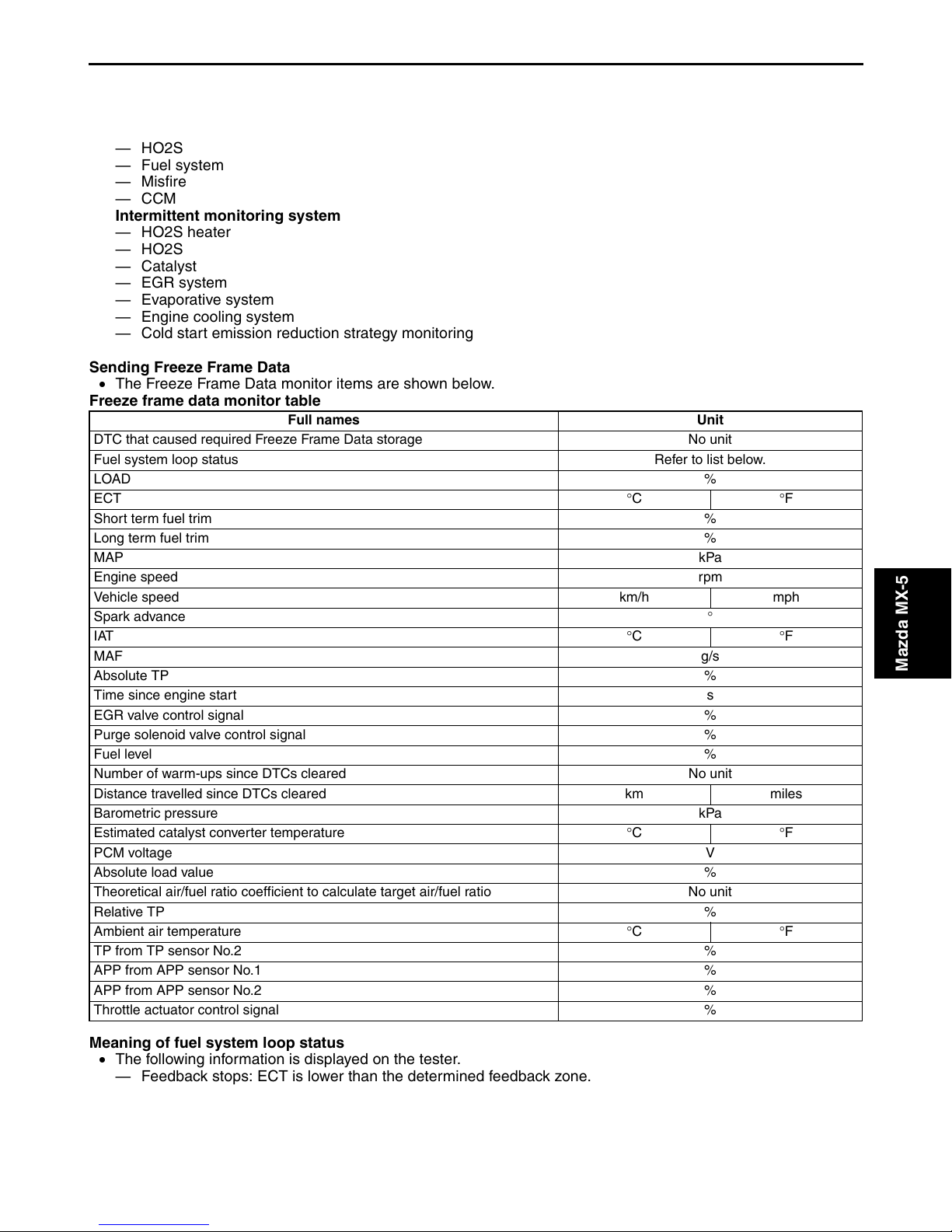
Sending Freeze Frame Data
• The Freeze Frame Data monitor items are shown below.
Freeze frame data monitor table
Full names Unit
DTC that caused required Freeze Frame Data storage No unit
Fuel system loop status Refer to list below.
LOAD %
ECT °C °F
Short term fuel trim %
Long term fuel trim %
MAP kPa
Engine speed rpm
Vehicle speed km/h mph
Spark advance °
IAT °C °F
MAF g/s
Absolute TP %
Time since engine start s
EGR valve control signal %
Purge solenoid valve control signal %
Fuel level %
Number of warm-ups since DTCs cleared No unit
Distance travelled since DTCs cleared km miles
Barometric pressure kPa
Estimated catalyst converter temperature °C °F
PCM voltage V
Absolute load value %
Theoretical air/fuel ratio coefficient to calculate target air/fuel ratio No unit
Relative TP %
Ambient air temperature °C °F
TP from TP sensor No.2 %
APP from APP sensor No.1 %
APP from APP sensor No.2 %
Throttle actuator control signal %
Mazda MX-5
Meaning of fuel system loop status
• The following information is displayed on the tester.
— Feedback stops: ECT is lower than the determined feedback zone.
— Feedback operating: HO2S being used for feedback is normal.
— Feedback stops: Open loop due to driving condition
— Feedback stops: Open loop due to detected system fault
— Feedback operating: Malfunction occurred in HO2S (rear) system
01-02–3
ON-BOARD DIAGNOSTIC [LF]
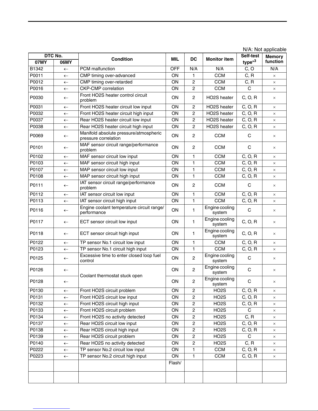
Sending Emission-related Malfunction Code
• The DTCs are shown below.
×: Applicable
N/A: Not applicable
DTC No.
07MY 06MY
B1342 ← PCM malfunction OFF N/A N/A C, O N/A
P0011 ← CMP timing over-advanced ON 1 CCM C, R ×
P0012 ← CMP timing over-retarded ON 2 CCM C, R ×
P0016 ← CKP-CMP correlation ON 2 CCM C ×
P0030 ←
P0031 ← Front HO2S heater circuit low input ON 2 HO2S heater C, O, R ×
P0032 ← Front HO2S heater circuit high input ON 2 HO2S heater C, O, R ×
P0037 ← Rear HO2S heater circuit low input ON 2 HO2S heater C, O, R ×
P0038 ← Rear HO2S heater circuit high input ON 2 HO2S heater C, O, R ×
P0069 ←
P0101 ←
P0102 ← MAF sensor circuit low input ON 1 CCM C, O, R ×
P0103 ← MAF sensor circuit high input ON 1 CCM C, O, R ×
P0107 ← MAP sensor circuit low input ON 1 CCM C, O, R ×
P0108 ← MAP sensor circuit high input ON 1 CCM C, O, R ×
P0111 ←
P0112 ← IAT sensor circuit low input ON 1 CCM C, O, R ×
P0113 ← IAT sensor circuit high input ON 1 CCM C, O, R ×
P0116 ←
P0117 ← ECT sensor circuit low input ON 1
P0118 ← ECT sensor circuit high input ON 1
P0122 ← TP sensor No.1 circuit low input ON 1 CCM C, O, R ×
P0123 ← TP sensor No.1 circuit high input ON 1 CCM C, O, R ×
P0125 ←
P0126 ←
P0128 ← ON 2
P0130 ← Front HO2S circuit problem ON 2 HO2S C, O, R ×
P0131 ← Front HO2S circuit low input ON 2 HO2S C, O, R ×
P0132 ← Front HO2S circuit high input ON 2 HO2S C, O, R ×
P0133 ← Front HO2S circuit problem ON 2 HO2S C ×
P0134 ← Front HO2S no activity detected ON 2 HO2S C, R ×
P0137 ← Rear HO2S circuit low input ON 2 HO2S C, O, R ×
P0138 ← Rear HO2S circuit high input ON 2 HO2S C, O, R ×
P0139 ← Rear HO2S circuit problem ON 2 HO2S C ×
P0140 ← Rear HO2S no activity detected ON 2 HO2S C, R ×
P0222 ← TP sensor No.2 circuit low input ON 1 CCM C, O, R ×
P0223 ← TP sensor No.2 circuit high input ON 1 CCM C, O, R ×
P0300 ← Random misfire detected
P0301 ← Cylinder No.1 misfire detected
Front HO2S heater control circuit
problem
Manifold absolute pressure/atmospheric
pressure correlation
MAF sensor circuit range/performance
problem
IAT sensor circuit range/performance
problem
Engine coolant temperature circuit range/
performance
Excessive time to enter closed loop fuel
control
Coolant thermostat stuck open
Condition MIL DC Monitor item
ON 2 HO2S heater C, O, R ×
ON 2 CCM C ×
ON 2 CCM C ×
ON 2 CCM C ×
ON 1
ON 2
ON 2
Flash/
ON
Flash/
ON
1 or 2 Misfire C, R ×
1 or 2 Misfire C, R ×
Engine cooling
system
Engine cooling
system
Engine cooling
system
Engine cooling
system
Engine cooling
system
Engine cooling
system
Self-test
type*
C ×
C, O, R ×
C, O, R ×
C ×
C ×
C ×
3
Memory
function
01-02–4
ON-BOARD DIAGNOSTIC [LF]
DTC No.
07MY 06MY
P0302 ← Cylinder No.2 misfire detected
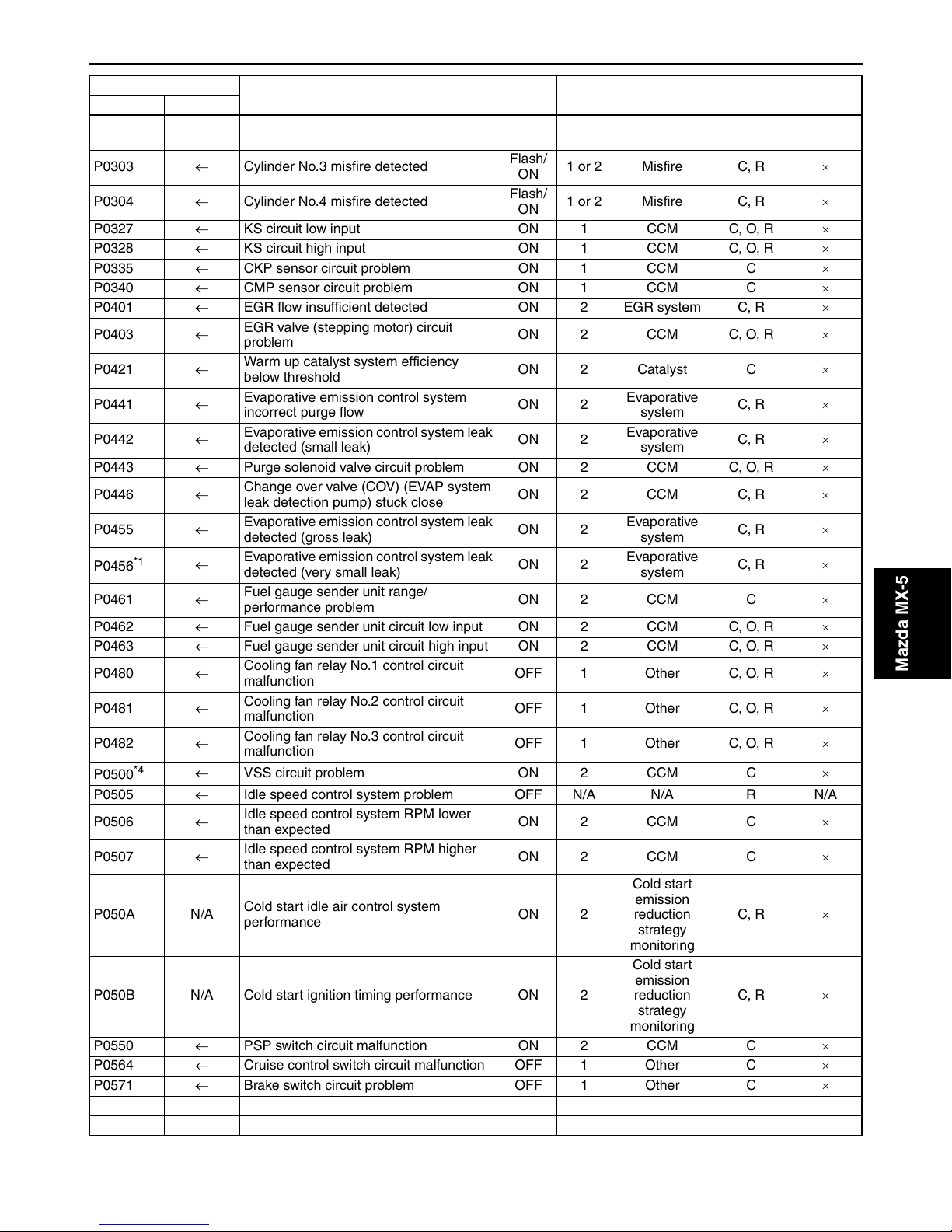
P0303 ← Cylinder No.3 misfire detected
P0304 ← Cylinder No.4 misfire detected
P0327 ← KS circuit low input ON 1 CCM C, O, R ×
P0328 ← KS circuit high input ON 1 CCM C, O, R ×
P0335 ← CKP sensor circuit problem ON 1 CCM C ×
P0340 ← CMP sensor circuit problem ON 1 CCM C ×
P0401 ← EGR flow insufficient detected ON 2 EGR system C, R ×
P0403 ←
P0421 ←
P0441 ←
P0442 ←
P0443 ← Purge solenoid valve circuit problem ON 2 CCM C, O, R ×
P0446 ←
P0455 ←
*1
P0456
P0461 ←
P0462 ← Fuel gauge sender unit circuit low input ON 2 CCM C, O, R ×
P0463 ← Fuel gauge sender unit circuit high input ON 2 CCM C, O, R ×
P0480 ←
P0481 ←
P0482 ←
*4
P0500
P0505 ← Idle speed control system problem OFF N/A N/A R N/A
P0506 ←
P0507 ←
P050A N/A
P050B N/A Cold start ignition timing performance ON 2
P0550 ← PSP switch circuit malfunction ON 2 CCM C ×
P0564 ← Cruise control switch circuit malfunction OFF 1 Other C ×
P0571 ← Brake switch circuit problem OFF 1 Other C ×
P0601 ← PCM memory check sum error ON 1 CCM C, O, R ×
P0602 ← PCM programming error ON 1 CCM C, O, R ×
←
← VSS circuit problem ON 2 CCM C ×
EGR valve (stepping motor) circuit
problem
Warm up catalyst system efficiency
below threshold
Evaporative emission control system
incorrect purge flow
Evaporative emission control system leak
detected (small leak)
Change over valve (COV) (EVAP system
leak detection pump) stuck close
Evaporative emission control system leak
detected (gross leak)
Evaporative emission control system leak
detected (very small leak)
Fuel gauge sender unit range/
performance problem
Cooling fan relay No.1 control circuit
malfunction
Cooling fan relay No.2 control circuit
malfunction
Cooling fan relay No.3 control circuit
malfunction
Idle speed control system RPM lower
than expected
Idle speed control system RPM higher
than expected
Cold start idle air control system
performance
Condition MIL DC Monitor item
Flash/
ON
Flash/
ON
Flash/
ON
ON 2 CCM C, O, R ×
ON 2 Catalyst C ×
ON 2
ON 2
ON 2 CCM C, R ×
ON 2
ON 2
ON 2 CCM C ×
OFF 1 Other C, O, R ×
OFF 1 Other C, O, R ×
OFF 1 Other C, O, R ×
ON 2 CCM C ×
ON 2 CCM C ×
ON 2
1 or 2 Misfire C, R ×
1 or 2 Misfire C, R ×
1 or 2 Misfire C, R ×
Evaporative
system
Evaporative
system
Evaporative
system
Evaporative
system
Cold start
emission
reduction
strategy
monitoring
Cold start
emission
reduction
strategy
monitoring
Self-test
3
type*
C, R ×
C, R ×
C, R ×
C, R ×
C, R ×
C, R ×
Memory
function
Mazda MX-5
01-02–5
ON-BOARD DIAGNOSTIC [LF]
DTC No.
07MY 06MY
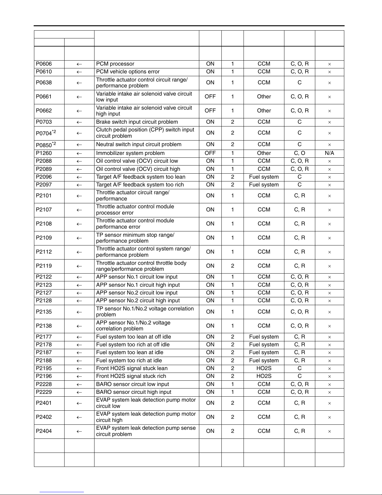
P0604 ←
P0606 ← PCM processor ON 1 CCM C, O, R ×
P0610 ← PCM vehicle options error ON 1 CCM C, O, R ×
P0638 ←
P0661 ←
P0662 ←
P0703 ← Brake switch input circuit problem ON 2 CCM C ×
*2
P0704
*2
P0850
P1260 ← Immobilizer system problem OFF 1 Other C, O N/A
P2088 ← Oil control valve (OCV) circuit low ON 1 CCM C, O, R ×
P2089 ← Oil control valve (OCV) circuit high ON 1 CCM C, O, R ×
P2096 ← Target A/F feedback system too lean ON 2 Fuel system C ×
P2097 ← Target A/F feedback system too rich ON 2 Fuel system C ×
P2101 ←
P2107 ←
P2108 ←
P2109 ←
P2112 ←
P2119 ←
P2122 ← APP sensor No.1 circuit low input ON 1 CCM C, O, R ×
P2123 ← APP sensor No.1 circuit high input ON 1 CCM C, O, R ×
P2127 ← APP sensor No.2 circuit low input ON 1 CCM C, O, R ×
P2128 ← APP sensor No.2 circuit high input ON 1 CCM C, O, R ×
P2135 ←
P2138 ←
P2177 ← Fuel system too lean at off idle ON 2 Fuel system C, R ×
P2178 ← Fuel system too rich at off idle ON 2 Fuel system C, R ×
P2187 ← Fuel system too lean at idle ON 2 Fuel system C, R ×
P2188 ← Fuel system too rich at idle ON 2 Fuel system C, R ×
P2195 ← Front HO2S signal stuck lean ON 2 HO2S C ×
P2196 ← Front HO2S signal stuck rich ON 2 HO2S C ×
P2228 ← BARO sensor circuit low input ON 1 CCM C, O, R ×
P2229 ← BARO sensor circuit high input ON 1 CCM C, O, R ×
P2401 ←
P2402 ←
P2404 ←
P2405 ←
P2407 ←
←
← Neutral switch input circuit problem ON 2 CCM C ×
PCM random access memory (RAM)
error
Throttle actuator control circuit range/
performance problem
Variable intake air solenoid valve circuit
low input
Variable intake air solenoid valve circuit
high input
Clutch pedal position (CPP) switch input
circuit problem
Throttle actuator circuit range/
performance
Throttle actuator control module
processor error
Throttle actuator control module
performance error
TP sensor minimum stop range/
performance problem
Throttle actuator control system range/
performance problem
Throttle actuator control throttle body
range/performance problem
TP sensor No.1/No.2 voltage correlation
problem
APP sensor No.1/No.2 voltage
correlation problem
EVAP system leak detection pump motor
circuit low
EVAP system leak detection pump motor
circuit high
EVAP system leak detection pump sense
circuit problem
EVAP system leak detection pump sense
circuit low input
EVAP system leak detection pump sense
circuit intermittent
Condition MIL DC Monitor item
ON 1 CCM C, O, R ×
ON 1 CCM C ×
OFF 1 Other C, O, R ×
OFF 1 Other C, O, R ×
ON 2 CCM C ×
ON 1 CCM C, R ×
ON 1 CCM C, R ×
ON 1 CCM C, R ×
ON 1 CCM C, R ×
ON 1 CCM C, R ×
ON 2 CCM C, R ×
ON 1 CCM C, O, R ×
ON 1 CCM C, O, R ×
ON 2 CCM C, R ×
ON 2 CCM C, R ×
ON 2 CCM C, R ×
ON 2 CCM C, R ×
ON 2 CCM C, R ×
Self-test
3
type*
Memory
function
01-02–6
ON-BOARD DIAGNOSTIC [LF]
DTC No.
07MY 06MY
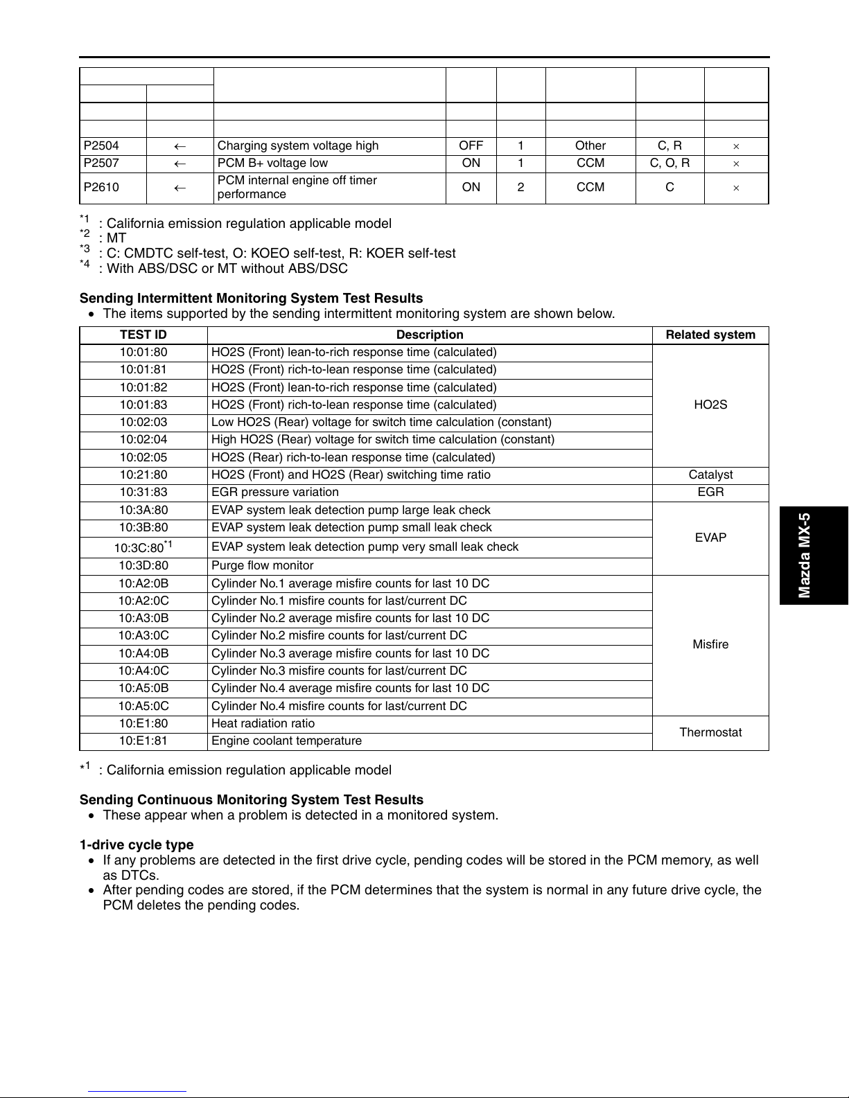
P2502 ← Charging system voltage problem OFF 1 Other C, R ×
P2503 ← Charging system voltage low OFF 1 Other C, R ×
P2504 ← Charging system voltage high OFF 1 Other C, R ×
P2507 ← PCM B+ voltage low ON 1 CCM C, O, R ×
P2610 ←
*1
: California emission regulation applicable model
*2
:MT
*3
: C: CMDTC self-test, O: KOEO self-test, R: KOER self-test
*4
: With ABS/DSC or MT without ABS/DSC
PCM internal engine off timer
performance
Condition MIL DC Monitor item
ON 2 CCM C ×
Self-test
3
type*
Memory
function
Sending Intermittent Monitoring System Test Results
• The items supported by the sending intermittent monitoring system are shown below.
TEST ID Description Related system
10:01:80 HO2S (Front) lean-to-rich response time (calculated)
10:01:81 HO2S (Front) rich-to-lean response time (calculated)
10:01:82 HO2S (Front) lean-to-rich response time (calculated)
10:01:83 HO2S (Front) rich-to-lean response time (calculated)
10:02:03 Low HO2S (Rear) voltage for switch time calculation (constant)
10:02:04 High HO2S (Rear) voltage for switch time calculation (constant)
10:02:05 HO2S (Rear) rich-to-lean response time (calculated)
10:21:80 HO2S (Front) and HO2S (Rear) switching time ratio Catalyst
10:31:83 EGR pressure variation EGR
10:3A:80 EVAP system leak detection pump large leak check
10:3B:80 EVAP system leak detection pump small leak check
10:3C:80
10:3D:80 Purge flow monitor
10:A2:0B Cylinder No.1 average misfire counts for last 10 DC
10:A2:0C Cylinder No.1 misfire counts for last/current DC
10:A3:0B Cylinder No.2 average misfire counts for last 10 DC
10:A3:0C Cylinder No.2 misfire counts for last/current DC
10:A4:0B Cylinder No.3 average misfire counts for last 10 DC
10:A4:0C Cylinder No.3 misfire counts for last/current DC
10:A5:0B Cylinder No.4 average misfire counts for last 10 DC
10:A5:0C Cylinder No.4 misfire counts for last/current DC
10:E1:80 Heat radiation ratio
10:E1:81 Engine coolant temperature
*1
EVAP system leak detection pump very small leak check
HO2S
EVAP
Misfire
Thermostat
Mazda MX-5
1
*
: California emission regulation applicable model
Sending Continuous Monitoring System Test Results
• These appear when a problem is detected in a monitored system.
1-drive cycle type
• If any problems are detected in the first drive cycle, pending codes will be stored in the PCM memory, as well
as DTCs.
• After pending codes are stored, if the PCM determines that the system is normal in any future drive cycle, the
PCM deletes the pending codes.
01-02–7
ON-BOARD DIAGNOSTIC [LF]
2-drive cycle type
• The code for a failed system is stored in the PCM memory in the first drive cycle. If the problem is not found in
the second drive cycle, the PCM determines that the system returned to normal or the problem was mistakenly
detected, and deletes the pending code when the ignition switch is turned to the ON position in the next drive
cycle. If the problem is found in the second drive cycle too, the PCM determines that the system has failed, and
stores the pending codes, and the DTCs.
• After pending codes are stored, if the PCM determines that the system is normal in any future drive cycle, the
PCM deletes the pending codes.
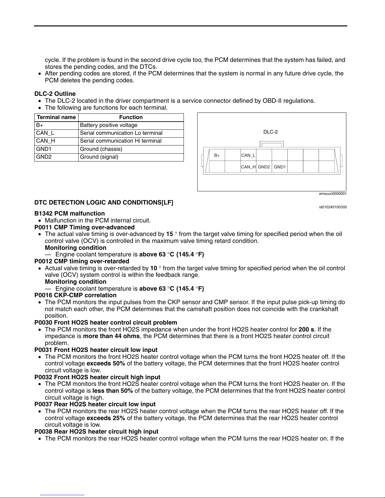
DLC-2 Outline
• The DLC-2 located in the driver compartment is a service connector defined by OBD-II regulations.
• The following are functions for each terminal.
Terminal name Function
B+ Battery positive voltage
CAN_L Serial communication Lo terminal
CAN_H Serial communication Hi terminal
GND1 Ground (chassis)
GND2 Ground (signal)
B+ CAN_L
End Of Sie
DTC DETECTION LOGIC AND CONDITIONS[LF]
B1342 PCM malfunction
• Malfunction in the PCM internal circuit.
P0011 CMP Timing over-advanced
• The actual valve timing is over-advanced by 15 ° from the target valve timing for specified period when the oil
control valve (OCV) is controlled in the maximum valve timing retard condition.
Monitoring condition
— Engine coolant temperature is above 63 °C {145.4 °F}
P0012 CMP timing over-retarded
• Actual valve timing is over-retarded by 10 ° from the target valve timing for specified period when the oil control
valve (OCV) system control is within the feedback range.
Monitoring condition
— Engine coolant temperature is above 63 °C {145.4 °F}
P0016 CKP-CMP correlation
• The PCM monitors the input pulses from the CKP sensor and CMP sensor. If the input pulse pick-up timing do
not match each other, the PCM determines that the camshaft position does not coincide with the crankshaft
position.
P0030 Front HO2S heater control circuit problem
• The PCM monitors the front HO2S impedance when under the front HO2S heater control for 200 s. If the
impedance is more than 44 ohms, the PCM determines that there is a front HO2S heater control circuit
problem.
P0031 Front HO2S heater circuit low input
• The PCM monitors the front HO2S heater control voltage when the PCM turns the front HO2S heater off. If the
control voltage exceeds 50% of the battery voltage, the PCM determines that the front HO2S heater control
circuit voltage is low.
P0032 Front HO2S heater circuit high input
• The PCM monitors the front HO2S heater control voltage when the PCM turns the front HO2S heater on. If the
control voltage is less than 50% of the battery voltage, the PCM determines that the front HO2S heater control
circuit voltage is high.
P0037 Rear HO2S heater circuit low input
• The PCM monitors the rear HO2S heater control voltage when the PCM turns the rear HO2S heater off. If the
control voltage exceeds 25% of the battery voltage, the PCM determines that the rear HO2S heater control
circuit voltage is low.
P0038 Rear HO2S heater circuit high input
• The PCM monitors the rear HO2S heater control voltage when the PCM turns the rear HO2S heater on. If the
control voltage is less than 57% of the battery voltage, the PCM determines that the rear HO2S heater control
circuit voltage is high.
DLC-2
GND1CAN_H GND2
amxuun0000001
id010245100300
01-02–8
ON-BOARD DIAGNOSTIC [LF]
P0069 Manifold absolute pressure/atmospheric pressure correlation
• PCM monitors differences between intake manifold vacuum and atmospheric pressure. If the difference is
below –12 kPa {–90 mmHg, –3.5 inHg} or above 12 kPa {90 mmHg, 3.5 inHg} when the following conditions
are met, the PCM determines that there is a MAP sensor performance problem.
MONITORING CONDITION
— 12—15 s from when ignition switch is turned off.
— Intake air temperature is above -10°C {14 °F}.
— Engine coolant temperature is above 70°C {158°F}.
P0101 MAF sensor circuit range/performance problem
• PCM monitors mass intake air flow amount when the engine is running.
— If the mass intake air flow amount is above 37 l/s for 5 s and the engine speed is below 2,000 rpm with the
engine running, the PCM determines that the detected mass intake air flow amount is too high.
— If the mass intake air flow amount is below 4.4—59 l/s (The value depends on engine speed.) for 5 s and
the engine speed is above 1,000 rpm with the engine running and the throttle opening angle above 50 %,
the PCM determines that detected the mass intake air flow amount is too low.
P0102 MAF sensor circuit low input
• The PCM monitors input voltage from the MAF sensor when the engine running. If the input voltage is below
0.21 V, the PCM determines that the MAF circuit has a malfunction.
P0103 MAF sensor circuit high input
• The PCM monitors the input voltage from the MAF sensor when the engine running. If the input voltage is
above 4.9 V, the PCM determines that the MAF circuit has a malfunction.
P0107 MAP sensor circuit low input
• The PCM monitors the input voltage from the MAP sensor when intake air temperature is above –10 °C {14
°F}. If the input voltage is below 0.1 V, the PCM determines that the MAP sensor circuit has a malfunction.
MONITORING CONDITIONS
— Calculated load: 13—32 %
P0108 MAP sensor circuit high input
• The PCM monitors the input voltage from the MAP sensor when intake air temperature is above –10 °C {14
°F}. If input the voltage is above 4.9 V, the PCM determines that the MAP sensor circuit has a malfunction.
MONITORING CONDITIONS
— Calculated load: 13—32 %
P0111 IAT sensor circuit range/performance problem
• If intake air temperature is higher than engine coolant temperature by 18 °C {32.4 °F} for 1.2 s with ignition
switch on
problem.
*: Ignition switch on when 6 h or more has passed since the previous ignition switch off
P0112 IAT sensor circuit low input
• The PCM monitors the IAT sensor signal. If the PCM detects that the IAT sensor voltage is below 0.16 V, the
PCM determines that the IAT sensor circuit has a malfunction.
P0113 IAT sensor circuit high input
• The PCM monitors the IAT sensor signal. If the PCM detects that the IAT sensor voltage is above 4.84 V, the
PCM determines that IAT sensor circuit has a malfunction.
P0116 Engine coolant temperature circuit range/performance
• The PCM monitors the maximum value and minimum value of engine coolant temperature when the engine is
started and 5 min have been passed after leaving the vehicle 6 h or more. If difference between maximum and
minimum values of engine coolant temperature is below 6 °C {10.8 °F} the PCM determines that there is an
ECT circuit range/performance problem.
P0117 ECT sensor circuit low input
• The PCM monitors the ECT sensor signal at PCM terminal 2AH. If the PCM detects the ECT sensor voltage
below 0.2 V, the PCM determines that the ECT sensor circuit has malfunction.
P0118 ECT sensor circuit high input
• The PCM monitors the ECT sensor signal at PCM terminal 2AH. If the PCM detects the ECT sensor voltage is
above 4.58 V, the PCM determines that the ECT sensor circuit has malfunction.
P0122 TP sensor No.1 circuit low input
• If the PCM detects that the TP sensor No.1 voltage is below 0.1 V while the engine is running, the PCM
determines that the TP sensor No.1 circuit has a malfunction.
P0123 TP sensor No.1 circuit high input
• If the PCM detects the TP sensor No.1 voltage is to be above 4.9 V after ignition switch to the ON position,
PCM determines that TP sensor No.1 circuit has a malfunction.
P0125 Excessive time to enter closed loop fuel control
• The PCM monitors the ECT sensor signal at PCM terminal 2AH after engine is started while the engine is cold.
If the engine coolant temperature does not reach the expected temperature for specified period, the PCM
determines that it has taken an excessive amount of time for the engine coolant temperature to reach the
temperature necessary to start closed-loop fuel control.
*
, the PCM determines that there is a intake air temperature sensor circuit range/performance
Mazda MX-5
01-02–9
ON-BOARD DIAGNOSTIC [LF]
P0126 Coolant thermostat stuck open
• If the ECT signal never exceeds 71 °C {160 °F} after engine start for specified period, PCM determines that the
coolant thermostat is stuck open.
MONITORING CONDITIONS
— IAT: above –10 °C {14 °F}
— Vehicle speed: over 6 km/h {3.7 mph}
P0128 Coolant thermostat stuck open
• PCM monitors MAF, IAT, VSS and EAT signals and calculate radiator’s heat radiation ratio while following
monitoring conditions are met. If calculated value exceeds threshold, PCM determines that the coolant
thermostat is stuck open.
MONITORING CONDITIONS
— IAT: above -10°C {14 °F}
— ECT at engine start: below 36 °C {97 °F}
— Difference between ECT at engine start and minimum IAT: below 6 °C {10.8 °F}
— Vehicle speed: over 30 km/h {18.6 mph}
P0130 Front HO2S circuit problem
• The PCM monitors the front HO2S impedance when under the front HO2S heater control. If the impedance is
more than 500 ohms, the PCM determines that there is a front HO2S circuit problem.
P0131 Front HO2S circuit low input
• The PCM monitors the input voltage from the front HO2S and the front HO2S output current when the engine is
running. If the input voltage is less than 1.8 V or the output current is less than –5 mA, the PCM determines
that the front HO2S circuit voltage is low.
P0132 Front HO2S circuit high input
• The PCM monitors the input voltage from the front HO2S and the front HO2S output current when the engine is
running. If the input voltage is more than 3.8 V or the output current is more than 5 mA, the PCM determines
that the front HO2S circuit voltage is high.
P0133 Front HO2S circuit problem
• The PCM monitors the peak differential value of oxygen sensor signal after A/F fluctuation being provided when
the following conditions are met. If the peak differential value is lower than the threshold value.
• The PCM determines that front HO2S circuit is slow.
MONITORING CONDITIONS
— HO2S heater, HO2S, and TWC Repair Verification Drive Mode
— Following conditions are met:
• Front HO2S heater monitor is completed.
• Fuel system loop status is closed loop fuel control.
— Engine speed: 1,750—3,500 rpm
— Charging efficiency: 25—63 % (at engine speed: 2,500 rpm)
— Intake air volume: 5—40 g/s
— Engine coolant temperature above 70 °C {158 °F}
P0134 Front HO2S no activity detected
• The PCM monitors the front HO2S element impedance when the following conditions are met. If the front
HO2S element impedance is 80 ohms or more, the PCM determines that front HO2S is not activated.
MONITORING CONDITIONS
— HO2S, HO2S heater and TWC Repair Verification Drive Mode
— Following conditions are met
• Time from engine start is above 30 s (ECT when engine start is 20 °C {68 °F}).
P0137 Rear HO2S circuit low input
• The PCM monitors input voltage from rear HO2S. If the input voltage from the rear HO2S is below 0.1 V for
35.2 s the PCM determines that circuit input is low.
MONITORING CONDITIONS
— HO2S, HO2S heater and TWC repair verification drive mode
— Following conditions are met.
• Engine speed is above 1,500 rpm.
• Engine coolant temperature is above 70 °C {158 °F}.
• Fuel injector control in rear HO2S closed loop control.
• The PCM monitors the input voltage from the rear HO2S when the following conditions are met. Under the
following monitoring conditions, if the input voltage from the rear HO2S does not even exceed 0.1 V though
the short term fuel trim is controlled up to 20.5 % for 9.6 s, the PCM determines that sensor circuit input is low.
MONITORING CONDITIONS
— HO2S, HO2S heater and TWC repair verification drive mode
— Following conditions are met for above 20.8 s.
• Engine speed is above 1,500 rpm.
• Engine coolant temperature is above 70 °C {158 °F}.
01-02–10
ON-BOARD DIAGNOSTIC [LF]
P0138 Rear HO2S circuit high input
• The PCM monitors input voltage from rear HO2S. If the input voltage from the rear HO2S sensor is above 1.2
V for 0.8 s, the PCM determines that circuit input is high.
P0139 Rear HO2S circuit problem
• The PCM monitors the rich (0.4 V) to lean (0.3 V) response time of the rear HO2S. The PCM measures the
response time when the following conditions are met. The PCM determines a rear HO2S response
deterioration malfunction when the measured response time is more than the threshold value (80 ms) five
consecutive times.
MONITORING CONDITIONS
— PCM Adaptive Memory Production, HO2S heater, HO2S, and TWC Repair Verification Drive Mode
— Following conditions are met:
• During deceleration fuel cut
• Engine speed is above 500 rpm.
• Engine coolant temperature is above 70 °C {158 °F}.
• Rear HO2S output voltage ia above 0.4 V.
• The PCM monitors for a time-out malfunction (when rear HO2S remains above 0.3 V for longer than a
specified period of time during fuel cut control). The PCM measures the amount of time from when the following
conditions are met until the rear HO2S output voltage drops below 0.3 V. The PCM determines a rear HO2S
time-out malfunction when the detected time is more than the threshold value (6 s) three consecutive times.
MONITORING CONDITIONS
— PCM Adaptive Memory Production, HO2S heater, HO2S, and TWC Repair Verification Drive Mode
— Following conditions are met:
• During deceleration fuel cut
• Engine speed is above 500 rpm.
• Engine coolant temperature is above 70 °C {158 °F}.
• Rear HO2S is activated (more than 0.55 V)
P0140 Rear HO2S no activity detected
• The PCM monitors the input voltage from the rear HO2S when the following conditions are met. Under the
following monitoring conditions, if the input voltage from the rear HO2S does not even exceed 0.55 V though
the short term fuel trim is controlled up to 20.5% for 9.6 s, the PCM determines that sensor circuit is not
activated.
MONITORING CONDITIONS
— HO2S, HO2S heater and TWC repair verification drive mode
— Following conditions are met for above 20.8 s
• Engine speed is above 1,500 rpm.
• Engine coolant temperature is above 70 °C {158 °F}.
— Rear HO2S voltage is above 0.1 V
P0222 TP sensor No.2 circuit low input
• If PCM detects TP sensor No.2 voltage is to be below 0.1 V after the ignition switch to the ON position, the
PCM determines that TP circuit has a malfunction.
P0223 TP sensor No.2 circuit high input
• If the PCM detects the TP sensor No.2 voltage is to be above 4.9 V after the ignition switch to the ON position,
the PCM determines that the TP circuit has a malfunction.
P0300 Random misfire detected
• The PCM monitors CKP sensor input signal interval time. The PCM calculates change of interval time for each
cylinder. If change of interval time exceeds preprogrammed criteria, the PCM detects misfire in the
corresponding cylinder. While the engine is running, the PCM counts number of misfires that occurred at 200
crankshaft revolutions and 1,000 crankshaft revolutions and calculates misfire ratio for each crankshaft
revolution. If the ratio exceeds the preprogrammed criteria, the PCM determines that a misfire, which can
damage catalytic converter or affect emission performance, has occurred.
P0301, P0302, P0303, P0304 Cylinder No.1, No.2, No.3, No.4 misfire detected
• The PCM monitors CKP sensor input signal interval time. The PCM calculates the change of interval time for
each cylinder. If the change of interval time exceeds the preprogrammed criteria, the PCM detects a misfire in
the corresponding cylinder. While the engine is running, the PCM counts number of misfires that occurred at
200 crankshaft revolutions and 1,000 crankshaft revolutions and calculates misfire ratio for each
crankshaft revolution. If the ratio exceeds the preprogrammed criteria, the PCM determines that a misfire,
which can damage catalytic converter or affect emission performance, has occurred.
P0327 KS circuit low input
• The PCM monitors input signal from the KS when the engine is running. If the input voltage is below 0.01 V the
PCM determines that the KS circuit has a malfunction.
P0328 KS circuit high input
• The PCM monitors the input signal from the KS when the engine is running. If the input voltage is above 4.58 V
the PCM determines that KS circuit has a malfunction.
Mazda MX-5
01-02–11
ON-BOARD DIAGNOSTIC [LF]
P0335 CKP sensor circuit problem
• If the PCM does not receive the input voltage from the CKP sensor for 4.2 s while the MAF is 1.95 g/s {0.25 lb/
min.} or above, the PCM determines that the CKP sensor circuit has a malfunction.
• If a malfunction is detected in the input pulse pattern from the CKP sensor.
P0340 CMP sensor circuit problem
• The PCM monitors the input voltage from the CMP sensor when the engine is running. If the PCM does not
receive the input voltage from the CMP sensor while the PCM receives the input signal from the CKP sensor,
the PCM determines that the CMP circuit has a malfunction.
• If a malfunction is detected in the input pulse pattern from the CMP sensor.
P0401 EGR flow insufficient detected
• PCM monitors difference in intake manifold pressures when EGR is operated and when it is stopped. If the
difference is too small, PCM determines that EGR flow insufficient.
P0403 EGR valve (stepping motor) circuit problem
• The PCM monitors the EGR valve control signal voltage and current. If the following conditions are met, the
PCM determines that there is the EGR control circuit problem.
— The PCM turns the EGR valve off, but the voltage of the EGR valve control signal remains low.
— The PCM turns the EGR valve on, but the current of the EGR valve control signal remains high.
P0421 Warm up catalyst system efficiency below threshold
• PCM compares number of front HO2S and rear HO2S inversions for a predetermined time. PCM monitors
number of inversions rear side performs while front side inverts for a specified number of times when the
following monitoring conditions are met, PCM detects inversion ratio. If inversion ratio is below threshold, PCM
determines that catalyst has deteriorated.
MONITORING CONDITION
— Calculated TWC temperature: more than 400 °C {752 °F}
— Engine speed: 1,500—3,000 rpm
— LOAD: 15—48 % (at engine speed 2,000 rpm)
P0441 Evaporative emission control system incorrect purge flow
• PCM measures the purge line pressure, which is the vacuum when a following condition. If vacuum between
charcoal canister and intake manifold does not reach the specified, PCM determines that the EVAP system has
clogging.
MONITORING CONDITION
— Engine speed: 1,500—3,500 rpm
— Throttle opening angle:11—20 %
— Vehicle speed: 69.5—136 km/h {43.2—84.5 mph} [MT]/34.5—136 km/h {21.4—84.5 mph} [AT]
P0442 Evaporative emission control system leak detected (small leak)
• PCM measures the pump load current (EVAP line pressure) when the specified period has passed after EVAP
system is sealed when monitoring conditions are met. If the load does not reach the reference current value
within the specified period, PCM determines that the EVAP system has small leak.
MONITORING CONDITION
— The ignition switch is turned off.
— IAT: 4.4—35 °C {40—95 °F}
— Battery voltage: 11 V or above
— Atmospheric pressure: 72.2 kPa {542 mmHg, 21.3 inHg} or above
— Fuel tank level: 15—85%
— Time from engine off: 5 h 10 min.
P0443 Purge solenoid valve circuit problem
• The PCM monitors the purge solenoid valve control signal voltage and current. If the following conditions are
met, the PCM determines that there is the purge solenoid valve control circuit problem.
— The PCM turns the purge solenoid valve off, but the voltage of the purge solenoid valve control signal
remains low.
— The PCM turns the purge solenoid valve on, but the current of the purge solenoid valve control signal
remains high.
P0446 Change over valve (COV) (EVAP system leak detection pump) stuck close
• The PCM monitors pump load current (EVAP line pressure), while evaporative leak monitor is operating. When
the decrease in pump load current is less than the specification after the reference current value has been
obtained, the PCM determines change over valve (COV) in EVAP system leak detection pump has a
malfunction.
01-02–12
ON-BOARD DIAGNOSTIC [LF]
P0455 Evaporative emission control system leak detected (gross leak)
• PCM measures the pump load current (EVAP line pressure) when the specified period has passed after EVAP
system is sealed when monitoring conditions are met. If the load does not reach the reference current value
within the specified period, PCM determines that the EVAP system has gross leak.
MONITORING CONDITION
— The ignition switch is turned off.
— IAT: 4.4—35 °C {40—95 °F}
— Battery voltage: 11 V or above
— Atmospheric pressure: 72.2 kPa {542 mmHg, 21.3 inHg} or above
— Fuel tank level: 15—85%
— Time from engine off: 5 h 10 min.
P0456 Evaporative emission control system leak detected (very small leak)
• PCM measure the pump load current (EVAP line pressure) when a specified period has passed after EVAP
system is sealed when monitoring conditions are met. If the load does not reach the reference load value or
rate of the load increase lower than the specified within a specified period, PCM determines that the EVAP
system has very small leak.
MONITORING CONDITION
— The ignition switch is turned off.
— IAT: 4.4—35 °C {40—95 °F}
— Battery voltage: 11 V or above
— Atmospheric pressure: 72.2 kPa {542 mmHg, 21.3 inHg} or above
— Fuel tank level: 15—85%
— Time from engine off: 5 h 10 min.
P0461 Fuel gauge sender unit range/performance problem
• The PCM monitors the fuel tank level difference before and after the PCM-calculated fuel consumption has
reached more than 25 L {26.4 US qt, 22 Imp qt}. If the difference is less than 5%, the PCM determines that
there is a fuel gauge sender unit range/performance problem.
P0462 Fuel gauge sender unit circuit low input
• The PCM monitors the fuel level signal and fuel gauge sender unit output voltage from the instrument cluster. If
the PCM detects a fuel level or fuel gauge sender unit output voltage is too low, the PCM determines that the
fuel gauge sender unit circuit has a malfunction.
P0463 Fuel gauge sender unit circuit high input
• The PCM monitors the fuel level signal and fuel gauge sender unit output voltage from the instrument cluster. If
the PCM detects a fuel level or fuel gauge sender unit output voltage is too high, the PCM determines that the
fuel gauge sender unit circuit has a malfunction.
P0480 Cooling fan relay No.1 control circuit malfunction
• The PCM monitors the cooling fan relay No.1 control signal voltage and current. If the following conditions are
met, the PCM determines that there is the cooling fan relay No.1 control circuit problem.
— The PCM turns the cooling fan relay No.1 off, but the voltage of the cooling fan relay No.1 control signal
remains low.
— The PCM turns the cooling fan relay No.1 on, but the current of the cooling fan relay No.1 control signal
remains high.
P0481 Cooling fan relay No.2 control circuit malfunction
• The PCM monitors the cooling fan relay No.2 control signal voltage and current. If the following conditions are
met, the PCM determines that there is the cooling fan relay No.2 control circuit problem.
— The PCM turns the cooling fan relay No.2 off, but the voltage of the cooling fan relay No.2 control signal
remains low.
— The PCM turns the cooling fan relay No.2 on, but the current of the cooling fan relay No.2 control signal
remains high.
P0482 Cooling fan relay No.3 control circuit malfunction
• The PCM monitors the cooling fan relay No.3 control signal voltage and current. If the following conditions are
met, the PCM determines that there is the cooling fan relay No.3 control circuit problem.
— The PCM turns the cooling fan relay No.3 off, but the voltage of the cooling fan relay No.3 control signal
remains low.
— The PCM turns the cooling fan relay No.3 on, but the current of the cooling fan relay No.3 control signal
remains high.
Mazda MX-5
01-02–13
ON-BOARD DIAGNOSTIC [LF]
P0500 VSS circuit problem
With ABS/DSC
• If an error in the wheel speed signal from the ABS/DSC HU/CM is detected by CAN when the following
conditions are met:
— Neutral switch and clutch pedal position switch are OFF
— Load is above 40 %
— Engine speed is 2,000 rpm or above
— Brake switch is OFF
— Shift lever position (P, N, R position) (AT)
MT without ABS/DSC
• Vehicle speed signal from vehicle speed sensor is below 3.7 km/h {2.3 mph} when the following conditions
are met:
— Neutral switch and clutch pedal position switch are OFF
— Load is above 40 %
— Engine speed is 2,000 rpm or above
— Brake switch is OFF
P0505 Idle speed control system problem
• The PCM cannot control idle speed toward target idle speed while KOER self test.
P0506 Idle speed control system RPM lower than expected
• Actual idle speed is lower than expected by 100 rpm for 14 s, when brake pedal is depressed (brake switch is
on) and steering wheel is held straight ahead (power steering pressure (PSP) switch is off).
P0507 Idle speed control system RPM higher than expected
• Actual idle speed is higher than expected by 200 rpm for 14 s, when the brake pedal is depressed (brake
switch is on) and steering wheel is held straight ahead (power steering pressure (PSP) switch is off).
P050A Cold start idle air control system performance
• Actual idle speed is lower than expected by 100 rpm for 8.4 s when the target idle speed correction value for
cold start is above 0 rpm or ignition retard value is above 10 ° CA.
Note
• If atmospheric pressure is less than 72.3 kPa {542 mmHg, 21.3 inHg} or intake air temperature is below
-10 °C {14 °F}, the PCM cancels diagnosis of P050A.
P050B Cold start ignition timing performance
• The PCM monitors actual ignition timing using the CKP sensor while electronic spark advance control fast idle
correction operating. If the ignition timing is out of specified range, the PCM determines that the ignition timing
at cold condition has performance problem.
P0550 PSP switch circuit malfunction
• The PCM monitors PSP switch signal at PCM terminal 2T. If input voltage is low voltage (switch stays on) for 1
min. when the VSS is above 60.0 km/h {37.4 mph} and ECT is above 60 °C {140 °F}, the PCM determines
that PSP switch circuit has malfunction.
P0564 Cruise control switch circuit malfunction
• The PCM monitors the cruise control switch signal at PCM terminal 1AQ. If the PCM detects that any one of
following switches (ON OFF, SET/-, SET/COAST, RES/+) remains on for 2 min, the PCM determines that the
cruise control switch circuit has a malfunction.
P0571 Brake switch circuit problem
• The PCM monitors changes in input voltage for brake switch No.1 and No.2. If the PCM detects that both brake
switches No.1 and No.2 remain on or off for 15 s, it determines that the brake switch circuit has a malfunction.
P0601 PCM memory check sum error
• PCM internal memory check sum error
P0602 PCM programming error
• No configuration data in the PCM
P0604 PCM random access memory (RAM) error
• PCM internal RAM malfunction.
P0606 PCM processor
• The PCM internal CPU malfunction
P0610 PCM vehicle options error
• PCM data configuration error
P0638 Throttle actuator control circuit range/performance problem
• The PCM compares the actual TP with the target TP when the engine is running. If the difference is more than
the specification, the PCM determines that there is a throttle actuator control circuit range/performance
problem.
01-02–14
ON-BOARD DIAGNOSTIC [LF]
P0661 Variable intake air solenoid valve circuit low input
• The PCM monitors the variable intake air solenoid valve control signal. If the PCM turns variable intake air
solenoid valve off but voltage at PCM terminal still remains low, the PCM determines that variable intake air
solenoid valve circuit has malfunction.
P0662 Variable intake air solenoid valve circuit high input
• The PCM monitors the variable intake air solenoid valve control signal at PCM terminal. If the PCM turns
variable intake air solenoid valve on but voltage at PCM terminal still remains high, the PCM determines that
the variable intake air solenoid valve circuit has malfunction.
P0703 Brake switch input circuit problem
• The PCM monitors changes in input voltage from the brake switch No.1. If the PCM does not the voltage
changes while alternately accelerating and decelerating 8 times, the PCM determines that the brake switch
No.1 circuit has a malfunction.
P0704 Clutch pedal position (CPP) switch input circuit problem
• The PCM monitors changes in input voltage from the CPP switch. If the PCM does not detect the voltage
changes while the vehicle runs with vehicle speed above 30 km/h {19 mph} and stops 8 times alternately, the
PCM determines that the CPP switch circuit has a malfunction.
P0850 Neutral switch input circuit problem
• The PCM monitors changes in input voltage from the neutral switch. If the PCM does not detect the voltage
changes while driving the vehicle at a vehicle speed above 30 km/h {19 mph} and clutch pedal turns press
and depress 10 times repeatedly, the PCM determines that the neutral switch circuit has a malfunction
P1260 Immobilizer system problem
• The instrument cluster detects an immobilizer system malfunction.
P2088 Oil control valve (OCV) circuit low
• The PCM monitors the OCV voltage. If the PCM detects the OCV control voltage (calculated from the OCV) is
below the threshold voltage (calculated from the battery positive voltage), the PCM determines that the OCV
circuit has a malfunction.
P2089 Oil control valve (OCV) circuit high
• The PCM monitors the OCV voltage. If the PCM detects that the OCV control voltage (calculated from the
OCV) is above the threshold voltage (calculated from battery positive voltage), the PCM determines that the
OCV circuit has a malfunction.
P2096 Target A/F feedback system too lean
• The PCM monitors the target A/F fuel trim when under the target A/F feedback control. If the fuel trim is more
than the specification, the PCM determines that the target A/F feedback system is too lean.
MONITORING CONDITION
— Rear HO2S voltage is above 0.1 V
P2097 Target A/F feedback system too rich
• The PCM monitors the target A/F fuel trim when under the target A/F feedback control. If the fuel trim is less
than specification, the PCM determines that the target A/F feedback system is too rich.
P2101 Throttle actuator circuit range/performance
• The PCM monitors the input voltage from the drive-by-wire relay when the PCM turns the drive-by-wire relay
on. If the input voltage is less than 5.0 V, the PCM determines that the drive-by-wire relay control circuit
voltage is low.
• The PCM monitors the input voltage from the drive-by-wire relay when the PCM turns the drive-by-wire relay
off. If the input voltage is more than 5.0 V the PCM determines that the drive-by-wire relay control circuit
voltage is high.
P2107 Throttle actuator control module processor error
• Throttle actuator control module internal processor error
P2108 Throttle actuator control module performance error
• PCM internal malfunction.
P2109 TP sensor minimum stop range/performance problem
• The PCM monitors the minimum TP when the closed TP learning is completed. If the TP is less than 6.03% or
more than 18.7%, the PCM determines that there is a TP sensor minimum stop range/performance problem.
P2112 Throttle actuator control system range/performance problem
• The PCM monitors the throttle actuator control duty ratio when the engine is running. If the duty ratio is more
than 95%, the PCM determines that there is a throttle actuator control system range/performance problem.
P2119 Throttle actuator control throttle body range/performance problem
• The PCM compares the actual TP with initial setting TP when the ignition switch is off. If the difference is less
than the specification, the PCM determines that there is a throttle actuator control circuit range/performance
problem.
P2122 APP sensor No.1 circuit low input
• The PCM monitors the input voltage from APP sensor No.1 when the engine is running. If the input voltage is
less than 0.35 V, the PCM determines that the APP sensor No.1 circuit input voltage is low.
Mazda MX-5
01-02–15
ON-BOARD DIAGNOSTIC [LF]
P2123 APP sensor No.1 circuit high input
• The PCM monitors the input voltage from APP sensor No.1 when the engine is running. If the input voltage is
above 4.8 V, the PCM determines that the APP sensor No.1 circuit input voltage is high.
P2127 APP sensor No.2 circuit low input
• The PCM monitors the input voltage from APP sensor No.2 when the engine is running. If the input voltage is
less than 0.35 V, the PCM determines that the APP sensor No.2 circuit has a malfunction.
P2128 APP sensor No.2 circuit high input
• The PCM monitors the input voltage from APP sensor No.2 when the engine is running. If the input voltage is
more than 4.8 V, the PCM determines that the APP sensor No.2 circuit has a malfunction.
P2135 TP sensor No.1/No.2 voltage correlation problem
• The PCM compares the input voltage from TP sensor No.1 with the input voltage from TP sensor No.2 when
the engine is running. If the difference is more than the specification, the PCM determines that there is a TP
sensor No.1/No.2 voltage correlation problem.
P2138 APP sensor No.1/No.2 voltage correlation problem
• The PCM compares the input voltage from APP sensor No.1 with the input voltage from APP sensor No.2 when
the engine is running. If the difference is more than the specification, the PCM determines that there is an APP
sensor No.1/No.2 angle correlation problem.
P2177 Fuel system too lean at off idle
• PCM monitors short term fuel trim (SHRTFT), long term fuel trim (LONGFT) during closed loop fuel control at
off-idle. If the LONGFT and the sum total of these fuel trims exceed preprogrammed criteria. PCM determines
that fuel system is too lean at off-idle.
P2178 Fuel system too rich at off idle
• PCM monitors short term fuel trim (SHRTFT), long term fuel trim (LONGFT) during closed loop fuel control at
off-idle. If the LONGFT and the sum total of these fuel trims exceed preprogrammed criteria. PCM determines
that fuel system is too rich at off-idle.
P2187 Fuel system too lean at idle
• PCM monitors short term fuel trim (SHRTFT) and long term fuel trim (LONGFT) during closed loop fuel control
at idle. If the LONGFT and the sum total of these fuel trims exceed preprogrammed criteria. PCM determines
that fuel system is too lean at idle.
P2188 Fuel system too rich at idle
• PCM monitors short term fuel trim (SHRTFT), long term fuel trim (LONGFT) during closed loop fuel control at
idle. If the LONGFT and the sum total of these fuel trims exceed preprogrammed criteria. PCM determines that
fuel system is too rich at idle.
P2195 Front HO2S signal stuck lean
• The PCM monitors the front HO2S output when the following conditions are met. If the output is more than
1.15 for 25 s, the PCM determines that the front HO2S signal remains lean.
MONITORING CONDITION
— ECT: more than 70 °C {158 °F}
— Engine speed: 1,000—3,200 rpm
— MAF amount: 6—80 g/s {0.80—10.58 lb/min}
— Target A/F feedback system status: feedback control
— Output voltage from the middle HO2S: more than 0.2 V
P2196 Front HO2S signal stuck rich
• The PCM monitors the front HO2S output current when the following conditions are met. If the output current is
less than 0.85 for 25 s, the PCM determines that the front HO2S signal remains rich.
MONITORING CONDITION
— ECT: more than 70 °C {158 °F}
— Engine speed: 1,000—3,200 rpm
— MAF amount: 6—80 g/s {0.80—10.58 lb/min}
— Target A/F feedback system status: feedback control
— Output voltage from the middle HO2S: less than 0.7 V
P2228 BARO sensor circuit low input
• PCM monitors input voltage from BARO sensor. If input voltage is below 2.1 V, PCM determines that BARO
sensor circuit has malfunction.
P2229 BARO sensor circuit high input
• PCM monitors input voltage from BARO sensor. If input voltage is above 4.0 V, PCM determines that BARO
sensor circuit has malfunction.
P2401 EVAP system leak detection pump motor circuit low
• The PCM monitors pump load current (EVAP line pressure), while evaporative leak monitor is operating. If the
pump load current is lower than specified, the PCM determines EVAP system leak detection pump motor circuit
has a malfunction.
01-02–16
 Loading...