

Page 1
Workshop Manual - General Information
2011 - RX- 8
General Information
VEHICLE IDENTIFICATION NUMBER (VIN) CODE
VEHICLE IDENTIFICATION NUMBER (VIN)
HOW TO USE THIS MANUAL
UNITS
SERVICE CAUTIONS
INSTALLATION OF RADIO SYSTEM
ELECTRICAL SYSTEM
JACKING POSITIONS, VEHICLE LIFT (2 SUPPORTS) AND SAFETY STAND (RIGID RACK) POSITIONS
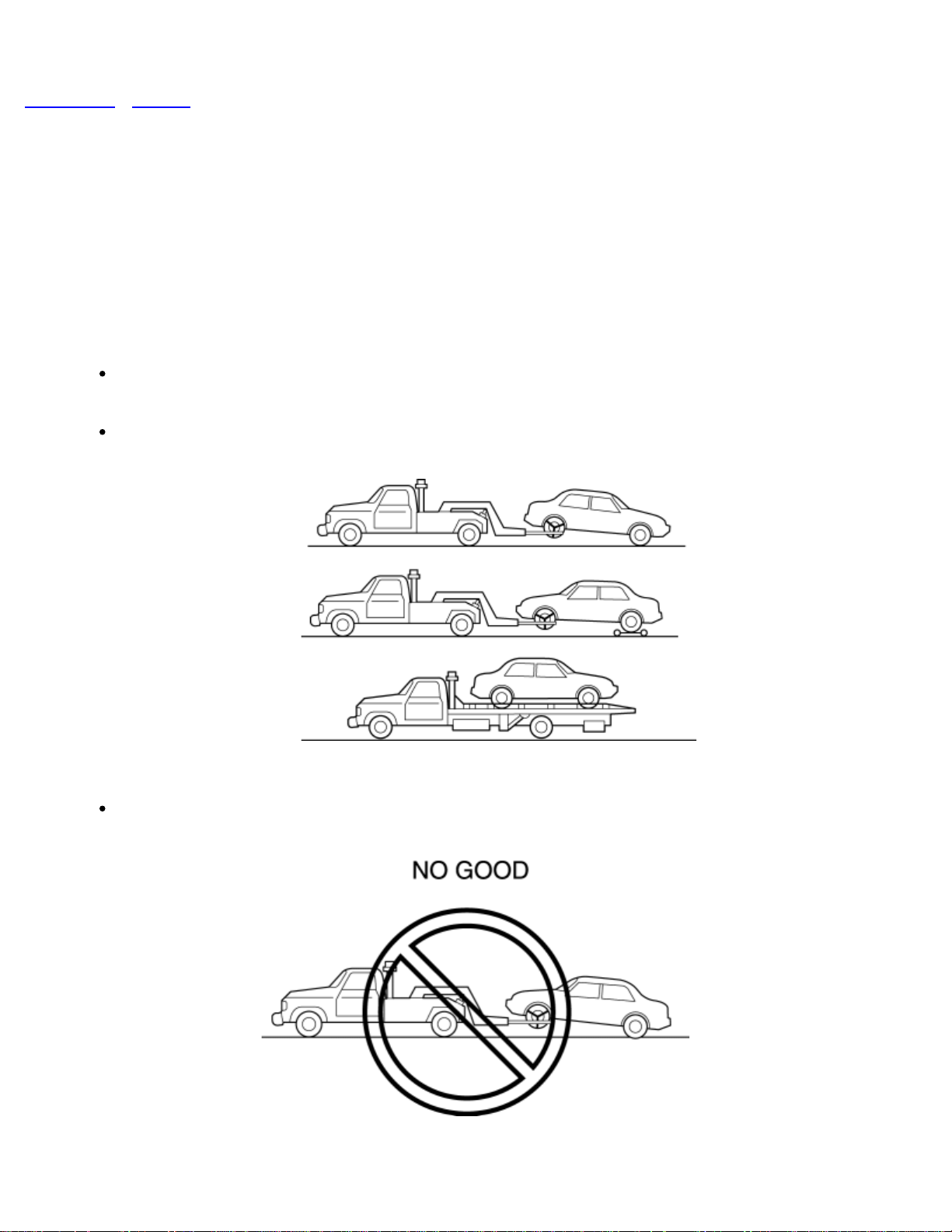
TOWING
TIEDOWN HOOK
IDENTIFICATION NUMBER LOCATIONS
SAE STANDARDS
ABBREVIATIONS
PRE-DELIVERY INSPECTION
SCHEDULED MAINTENANCE
Page 2
< Previous Next >
2011 - RX-8 - General Information
UNITS
Electric current A (ampere)
Electric power W (watt)
Electric resistanceohm
Electric voltage V (volt)
Length
Negative pressure
Positive pressure
mm (millimeter)
in (inch)
kPa (kilo pascal)
mmHg (millimeters of mercury)
inHg (inches of mercury)
kPa (kilo pascal)
kgf/cm2 (kilogram force per square centimeter)
psi (pounds per square inch)
Number of
revolutions
rpm (revolutions per minute)
N·m (Newton meter)
Page 3
kgf·m (kilogram force meter)
Torque
Volume
kgf·cm (kilogram force centimeter)
ft·lbf (foot pound force)
in·lbf (inch pound force)
L (liter)
US qt (U.S. quart)
Imp qt (Imperial quart)
ml (milliliter)
cc (cubic centimeter)
cu in (cubic inch)
fl oz (fluid ounce)
g (gram)
Weight
oz (ounce)
Conversion to SI Units (Système International d'Unités)
All numerical values in this manual are based on SI units. Numbers shown in conventional
units are converted from these values.
Rounding Off
Converted values are rounded off to the same number of places as the SI unit value. For
example, if the SI unit value is 17.2 and the value after conversion is 37.84, the converted
value will be rounded off to 37.8.
Page 4

Upper and Lower Limits
When the data indicates upper and lower limits, the converted values are rounded down if
the SI unit value is an upper limit and rounded up if the SI unit value is a lower limit.
Therefore, converted values for the same SI unit value may differ after conversion. For
example, consider 2.7 kgf/cm
210—260 kPa {2.1—2.7 kgf/cm2, 30—38 psi}
270—310 kPa {2.7—3.2 kgf/cm2, 39—45 psi}
The actual converted values for 2.7 kgf/cm2 are 264 kPa and 38.4 psi. In the first
specification, 2.7 is used as an upper limit, so the converted values are rounded down to
260 and 38. In the second specification, 2.7 is used as a lower limit, so the converted
values are rounded up to 270 and 39.
< Previous Next >
2
in the following specifications:
© 2010 Mazda North American Operations, U.S.A.
Back to Top
Page 5
Next >
2011 - RX-8 - General Information
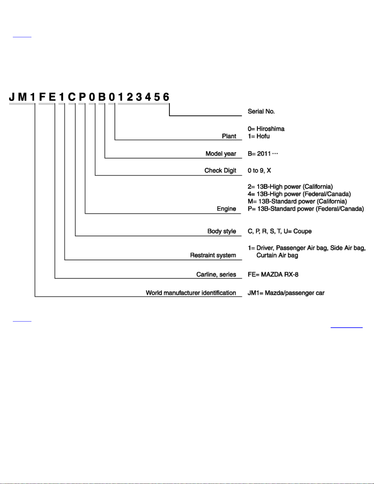
VEHICLE IDENTIFICATION NUMBER (VIN) CODE
Next >
Back to Top
© 2010 Mazda North American Operations, U.S.A.
Page 6

< Previous Next >
2011 - RX-8 - General Information
VEHICLE IDENTIFICATION NUMBER (VIN)
JM1 FE1*2*B# 400001—
JM1 FE1*4*B# 400001—
JM1 FE1*M*B# 400001—
JM1 FE1*P*B# 400001—
< Previous Next >
© 2010 Mazda North American Operations, U.S.A.
Back to Top
Page 7
< Previous Next >
2011 - RX-8 - General Information
SAE STANDARDS
In accordance with new regulations, SAE (Society of Automotive Engineers) standard
names and abbreviations are now used in this manual. The table below lists the names
and abbreviations that have been used in Mazda manuals up to now and their SAE
equivalents.
SAE Standard
Remark
Abbreviation Name Abbreviation Name
AP Accelerator Pedal MIL Malfunction Indicator Lamp
APP Accelerator Pedal Position MAP Manifold Absolute Pressure
ACL Air Cleaner MAF sensor Mass Air Flow Sensor
A/C Air Conditioning MFL Multiport Fuel Injection
A/F sensor Air Fuel Ratio Sensor OBD On–board Diagnostic System
BARO Barometric Pressure OL Open Loop
SAE Standard
Remark
B+ Battery Positive Voltage OC Oxidation Catalytic Converter
CMP sensor Camshaft Position Sensor O2S Oxygen sensor
CAC Charge Air Cooler PNP Park/Neutral Position
CLS Closed Loop System PSP Power Steering Pressure
CTP Closed Throttle Position PCM Powertrain Control Module #3
Page 8
CPP Clutch Pedal Position
PAIR
CIS
CKP sensor
DTM Diagnostic Test Mode #1
DTC Diagnostic Test Code(s) SAPV Secondary Air Pulse Valve
DI Distributor Ignition
DLI Distributorless Ignition
Continuous Fuel Injection
System
Crankshaft Position
Sensor
AIR Secondary Air Injection
SFI
Pulsed Secondary Air
Injection
Sequential Multiport Fuel
Injection
Pulsed injection
Injection with air
pumpDLC Data Link Connector
EI Electronic Ignition #2 3GR Third Gear
ECT
EM Engine Modification TB Throttle Body
EVAP Evaporative Emission TP sensor Throttle Position Sensor
EGR Exhaust Gas Recirculation TCC Torque Converter Clutch
FC Fan Control
FF Flexible Fuel
4GR Fourth Gear TR
Engine Coolant
Temperature
TWC
TCM
Three Way Catalytic
Converter
Transmission (Transaxle)
Control Module
Transmission (Transaxle)
Range
GEN Generator TC Turbocharger
GND Ground VSS Vehicle Speed Sensor
Page 9
VR Voltage Regulator
HO2S Heated Oxygen Sensor
IAC Idle Air Control
IAT Intake Air Temperature
KS Knock Sensor WOT Wide Open Throttle
#1: Diagnostic trouble codes depend on the diagnostic test mode.
#2: Controlled by the PCM
#3: Device that controls engine and powertrain
#4: Directly connected to exhaust manifold
With
heater
VAF sensor Volume Air Flow Sensor
WU-TWC
Warm Up Three Way
Catalytic Converter
#4
< Previous Next >
Back to Top
© 2010 Mazda North American Operations, U.S.A.
Page 10
< Previous Next >
2011 - RX-8 - General Information
HOW TO USE THIS MANUAL
Range of Topics
This manual contains procedures for performing all required service operations. The procedures are divided into the following five basic
operations:
Removal/Installation
Disassembly/Assembly
Replacement
Inspection
Adjustment
Simple operations which can be performed easily just by looking at the vehicle (i.e., removal/installation of parts, jacking, vehicle lifting,
cleaning of parts, and visual inspection) have been omitted.
Service Procedure
Inspection, adjustment
Inspection and adjustment procedures are divided into steps. Important points regarding the location and contents of the procedures are
explained in detail and shown in the illustrations.
Page 11
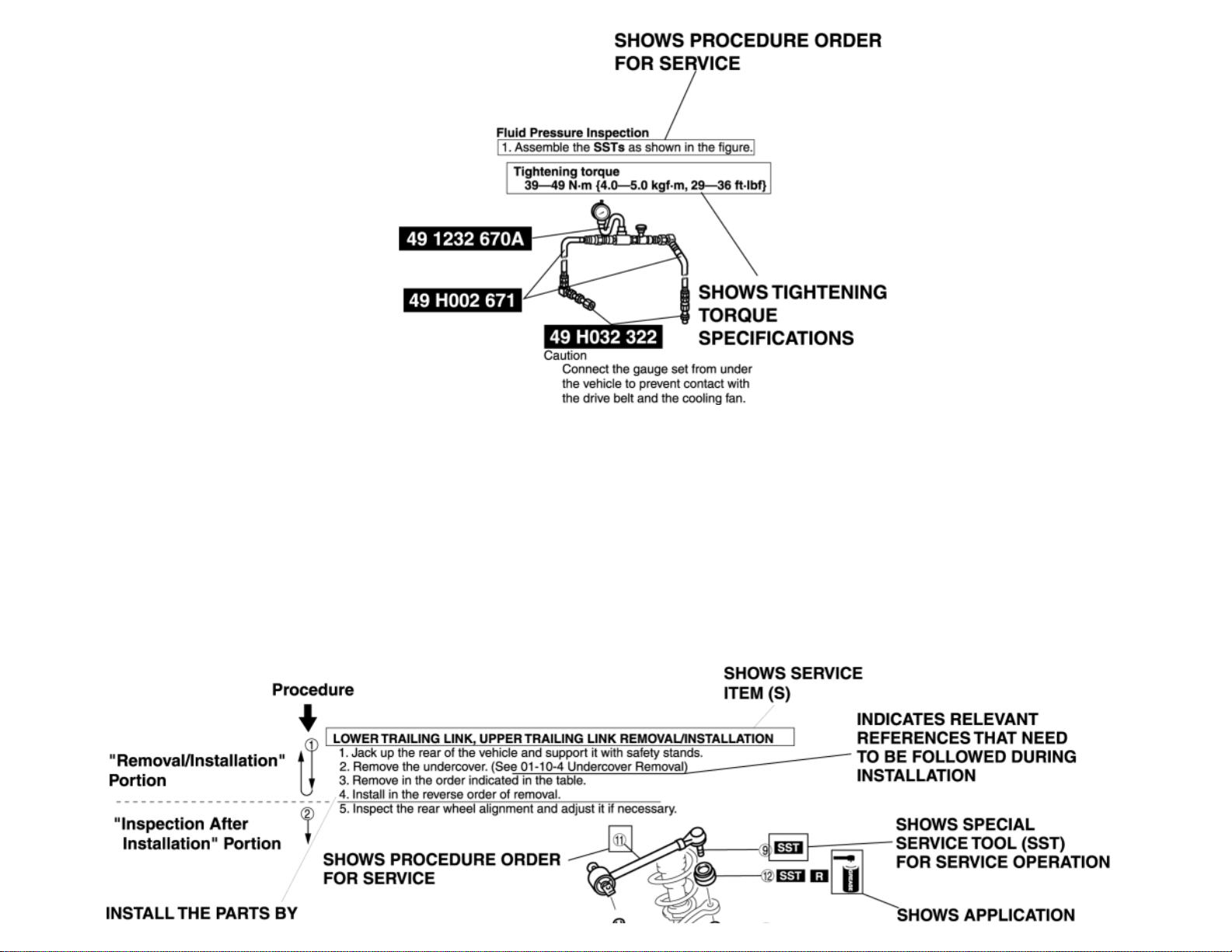
Repair procedure
1. Most repair operations begin with an overview illustration. It identifies the components, shows how the parts fit together, and describes visual
part inspection. However, only removal/installation procedures that need to be performed methodically have written instructions.
2. Expendable parts, tightening torques, and symbols for oil, grease, and sealant are shown in the overview illustration. In addition, symbols
indicating parts requiring the use of special service tools or equivalent are also shown.
3. Procedure steps are numbered and the part that is the main point of that procedure is shown in the illustration with the corresponding
number. Occasionally, there are important points or additional information concerning a procedure. Refer to this information when servicing the
related part.
Page 12
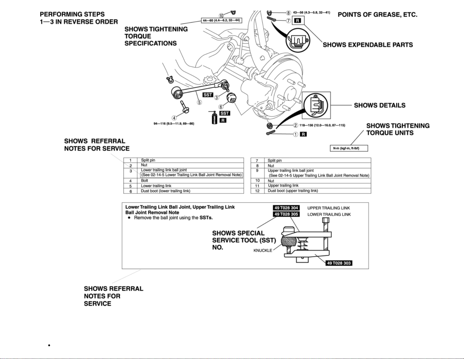
Symbols
There are eight symbols indicating oil, grease, fluids, sealant, and the use of SST or equivalent. These symbols show application points or
Page 13
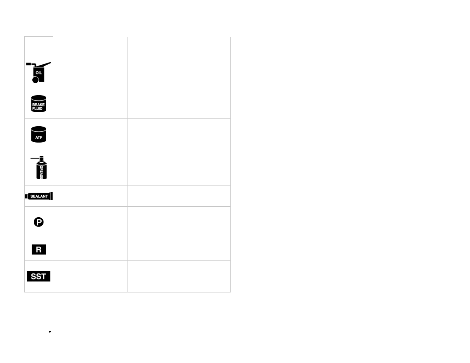
use of these materials during service.
Symbol Meaning Kind
Apply oil New appropriate engine oil or gear oil
Apply brake fluid New appropriate brake fluid
Apply automatic
transaxle/transmission fluid
Apply grease Appropriate grease
Apply sealant Appropriate sealant
Apply petroleum jelly
Replace part O–ring, gasket, etc.
Use SST or
equivalent
New appropriate automatic
transaxle/transmission fluid
Appropriate
petroleum jelly
Appropriate tools
Advisory Messages
You will find several Warnings, Cautions, Notes, Specifications and Upper and Lower Limits in this manual.
Page 14

Warning
A Warning indicates a situation in which serious injury or death could result if the warning is ignored.
Caution
A Caution indicates a situation in which damage to the vehicle or parts could result if the caution is ignored.
Note
A Note provides added information that will help you to complete a particular procedure.
Specification
The values indicate the allowable range when performing inspections or adjustments.
Upper and lower limits
The values indicate the upper and lower limits that must not be exceeded when performing inspections or adjustments.
Troubleshooting Procedure
Basic flow of troubleshooting
Page 15
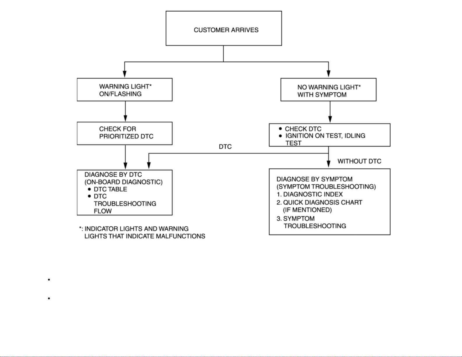
DTC troubleshooting flow (on–board diagnostic)
Diagnostic trouble codes (DTCs) are important hints for repairing malfunctions that are difficult to simulate. Perform the specific DTC
diagnostic inspection to quickly and accurately diagnose the malfunction.
The on–board diagnostic function is used during inspection. When a DTC is shown specifying the cause of a malfunction, continue the
diagnostic inspection according to the items indicated by the on–board diagnostic function.
Diagnostic index
Page 16
The diagnostic index lists the symptoms of specific malfunctions. Select the symptoms related or most closely relating to the malfunction.
Quick diagnosis chart (If mentioned)
The quick diagnosis chart lists diagnosis and inspection procedures to be performed specifically relating to the cause of the malfunction.
Symptom troubleshooting
Symptom troubleshooting quickly determines the location of the malfunction according to symptom type.
Procedures for Use
Using the basic inspection (section 05)
Perform the basic inspection procedure before symptom troubleshooting.
Perform each step in the order shown.
The reference column lists the location of the detailed procedure for each basic inspection.
Although inspections and adjustments are performed according to the reference column procedures, if the cause of the malfunction is
discovered during basic inspection, continue the procedures as indicated in the action column.
Page 17
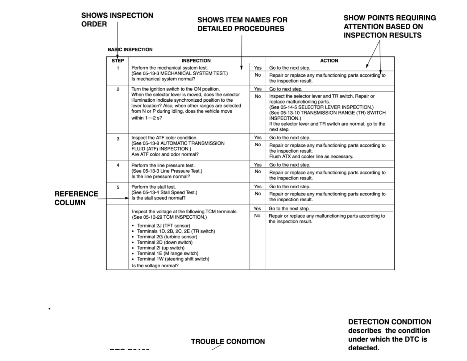
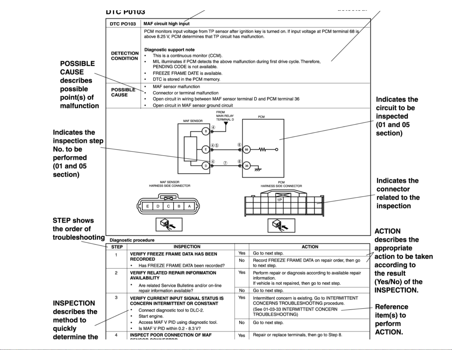
Using the DTC troubleshooting flow
DTC troubleshooting flow shows diagnostic procedures, inspection methods, and proper action to take for each DTC.
Page 18
Page 19
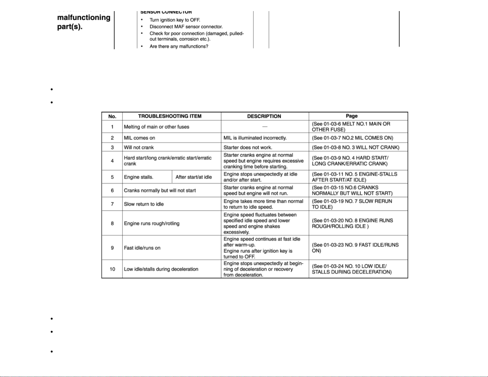
Using the diagnostic index
Malfunction symptoms are listed in the diagnostic index under symptom troubleshooting.
The exact malfunction symptoms can be selected by following the index.
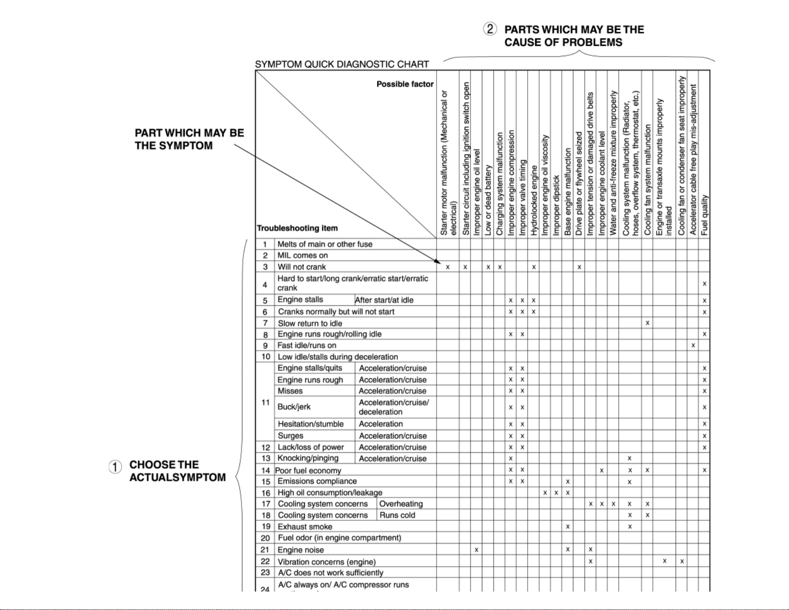
Using the quick diagnosis chart
The chart lists the relation between the symptom and the cause of the malfunction.
The chart is effective in quickly narrowing down the relation between symptom and cause of the malfunction. It also specifies a range of
common causes when multiple malfunction symptoms occur.
The appropriate diagnostic inspection relating to a malfunction cause as specified by the symptoms can be selected by looking down the
diagnostic inspection column of the chart.
Page 20
Page 21
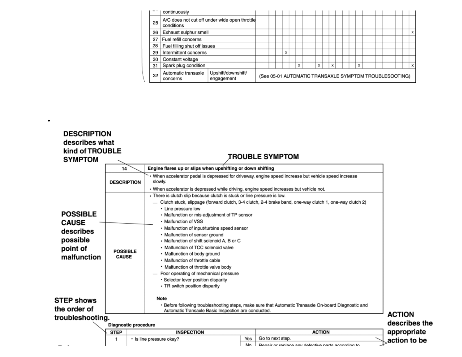
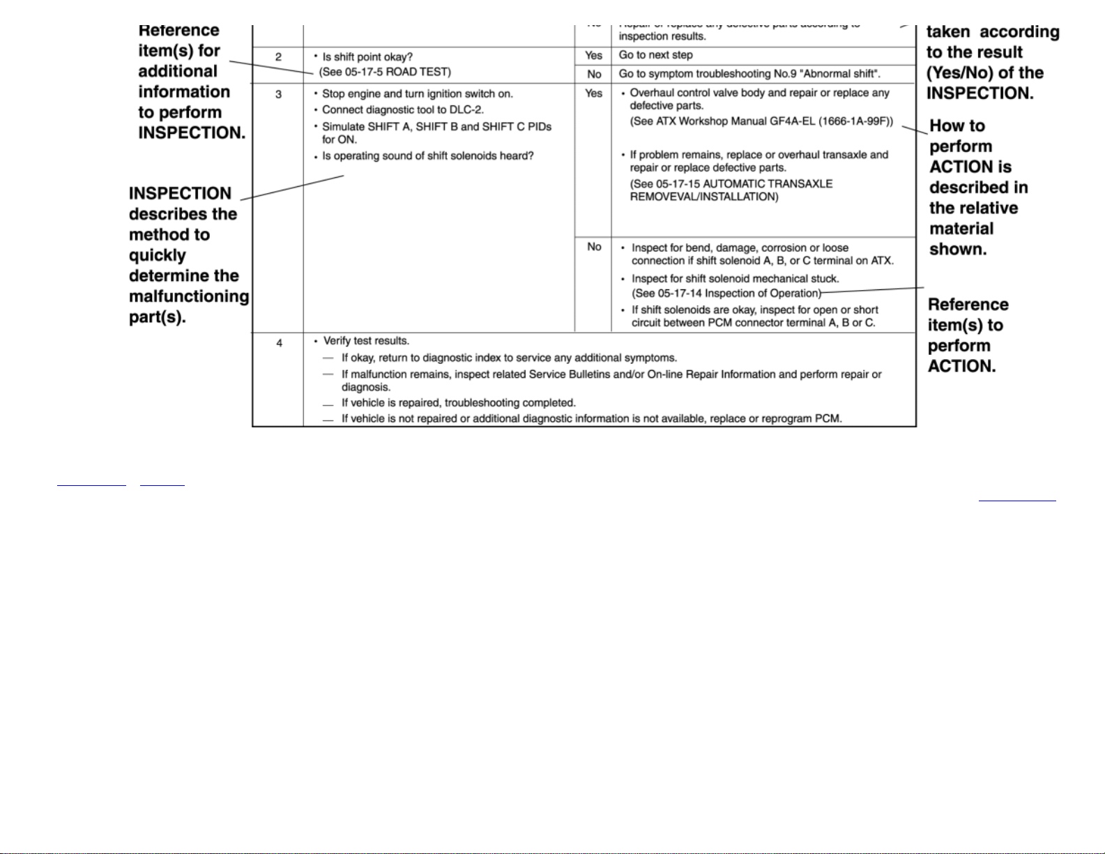
Using the symptom troubleshooting
Symptom troubleshooting shows diagnostic procedures, inspection methods, and proper action to be taken for each trouble symptom.
Page 22
< Previous Next >
Back to Top
© 2010 Mazda North American Operations, U.S.A.
Page 23
< Previous Next >
2011 - RX-8 - General Information
SERVICE CAUTIONS
Injury/damage Prevention Precautions
Depending on the vehicle, the cooling fan may operate suddenly even when the ignition
switch is turned off. Therefore, keep hands and tools away from the cooling fan even if the
cooling fan is not operating to prevent injury to personnel or damage to the cooling fan.
Always disconnect the negative battery cable when servicing the cooling fan or parts near
the cooling fan.
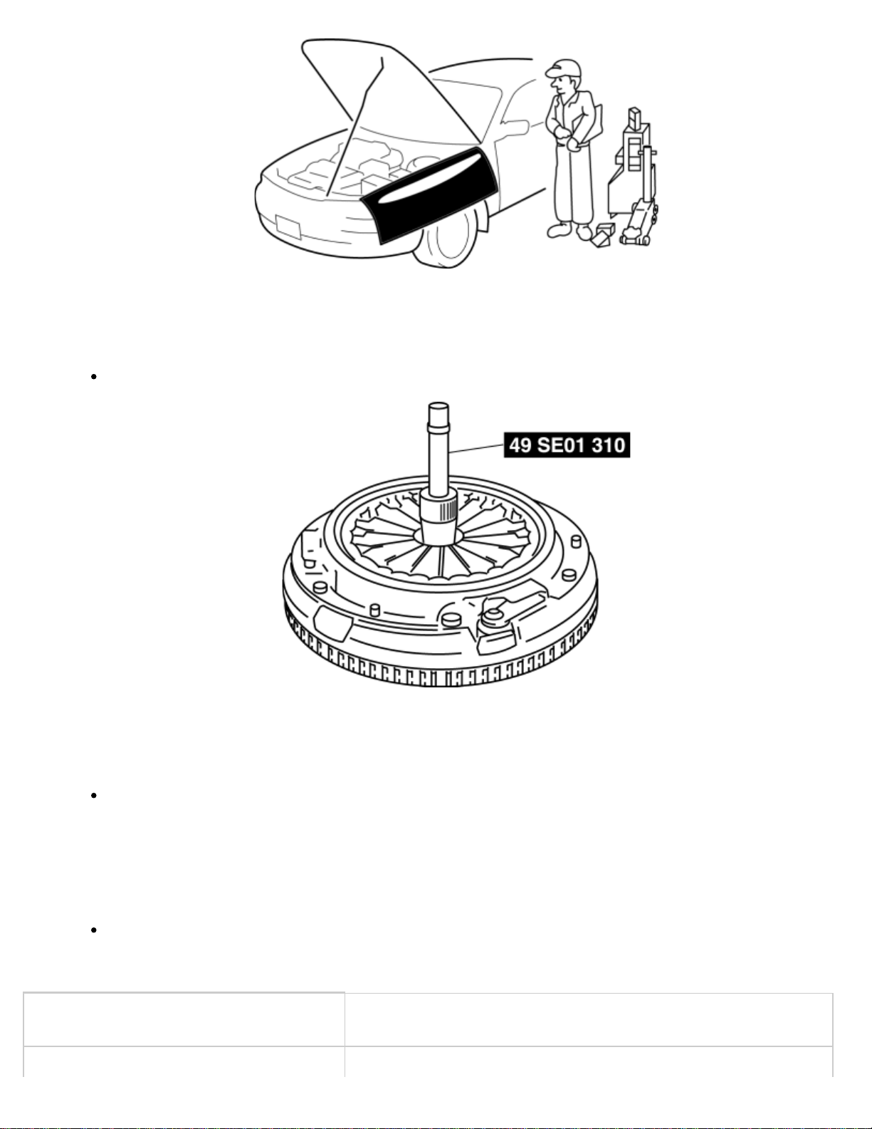
Protection of the Vehicle
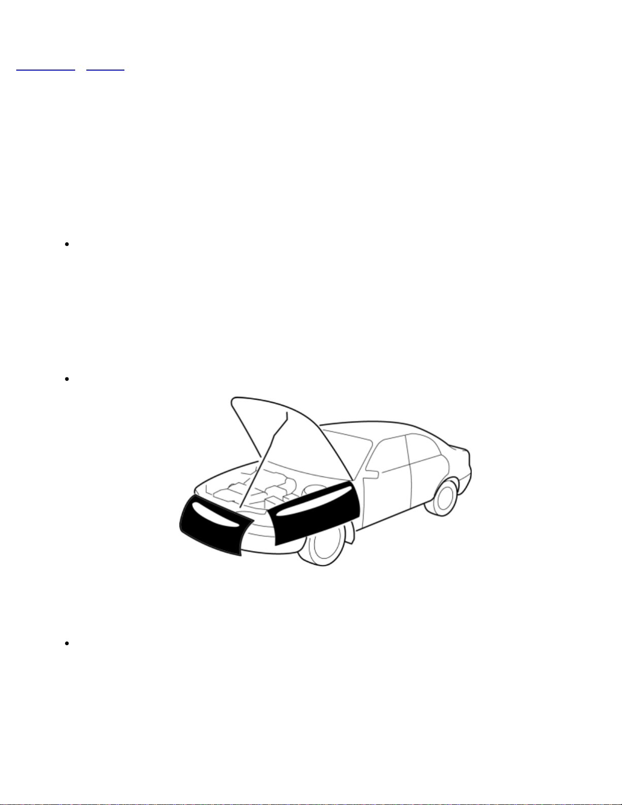
Always be sure to cover fenders, seats and floor areas before starting work.
Preparation of Tools and Measuring Equipment
Be sure that all necessary tools and measuring equipment are available before starting any
work.
Page 24
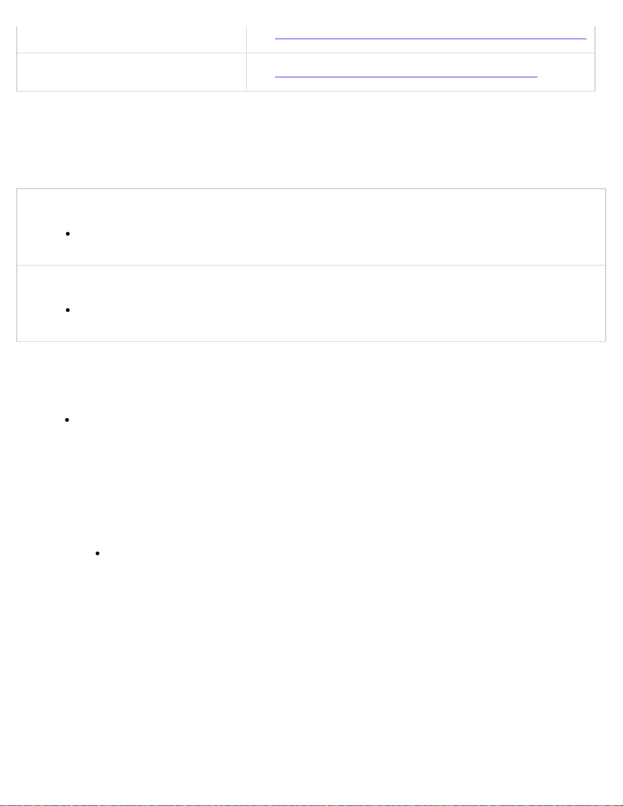
Special Service Tools
Use special service tools or the equivalent when they are required.
Malfunction Diagnosis System
Use the Mazda Modular Diagnostic System (M-MDS) or equivalent for malfunction
diagnosis.
Negative Battery Cable Disconnection/Connection
Perform the following system initialization after disconnecting the negative battery cable.
SYSTEM PAGE
Page 25
Steering angle sensor (Vehicles with DSC)(See STEERING ANGLE SENSOR INITIALIZATION PROCEDURE.)
Power window system (See POWER WINDOW INITIALIZATION PROCEDURE.)
Required procedure following negative battery cable disconnection
SAS control module
Disconnect the negative battery cable and wait for 1 min. or more to allow the back-up
power supply to deplete its stored power.
Clock and audio
The clock and audio memory settings will be erased, therefore record the clock and audio
settings prior to disconnecting, and reset them after reconnecting.
Oil Leakage Inspection
Use either of the following procedures to identify the type of oil that is leaking:
Using UV light (black light)
1. Remove any oil on the engine or transaxle/transmission.
NOTE:
Referring to the fluorescent dye instruction manual, mix the specified amount of
dye into the engine oil or ATF (or transaxle/transmission oil).
2. Pour the fluorescent dye into the engine oil or ATF (or transaxle/transmission oil).
3. Allow the engine to run for 30 min.
4. Inspect for dye leakage by irradiating with UV light (black light), and identify the type of oil
that is leaking.
5. If no dye leakage is found, allow the engine to run for another 30 min. or drive the vehicle
then reinspect.
6. Find where the oil is leaking from, then make necessary repairs.
NOTE:
Page 26
To determine whether it is necessary to replace the oil after adding the
fluorescent dye, refer to the fluorescent dye instruction manual.
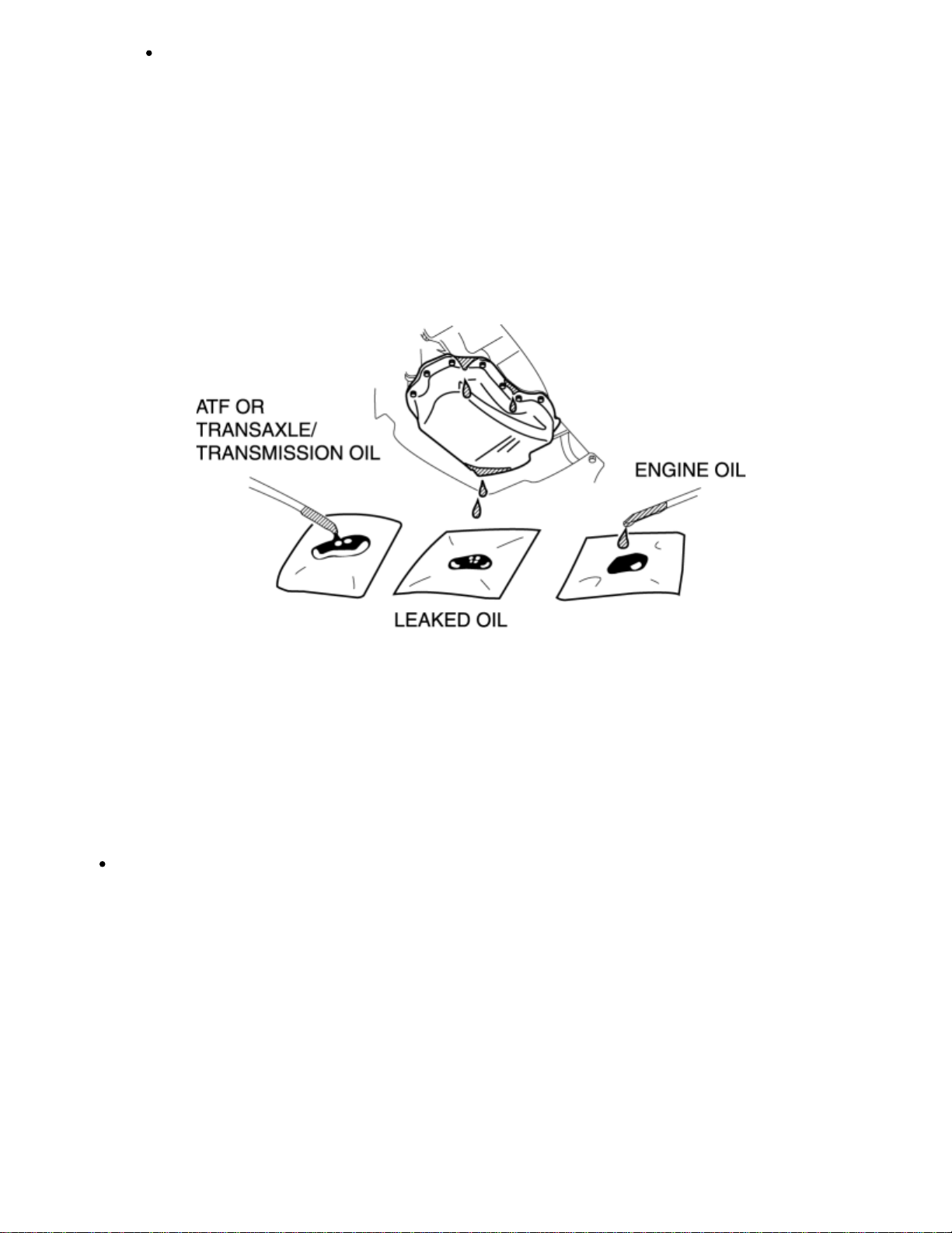
Not using UV light (black light)
1. Gather some of the leaking oil using an absorbent white tissue.
2. Take samples of engine oil and ATF (or transaxle/transmission oil), both from the dipstick,
and place them next to the leaked oil already on the tissue.
3. Compare the appearance and smell, and identify the type of oil that is leaking.
4. Remove any oil on the engine or transaxle/transmission.
5. Allow the engine to run for 30 min.
6. Check the area where the oil is leaking, then make necessary repairs.
Removal of Parts
While correcting a problem, also try to determine its cause. Begin work only after first
learning which parts and sub-components must be removed and disassembled for
replacement or repair. After removing the part, plug all holes and ports to prevent foreign
material from entering.
Page 27
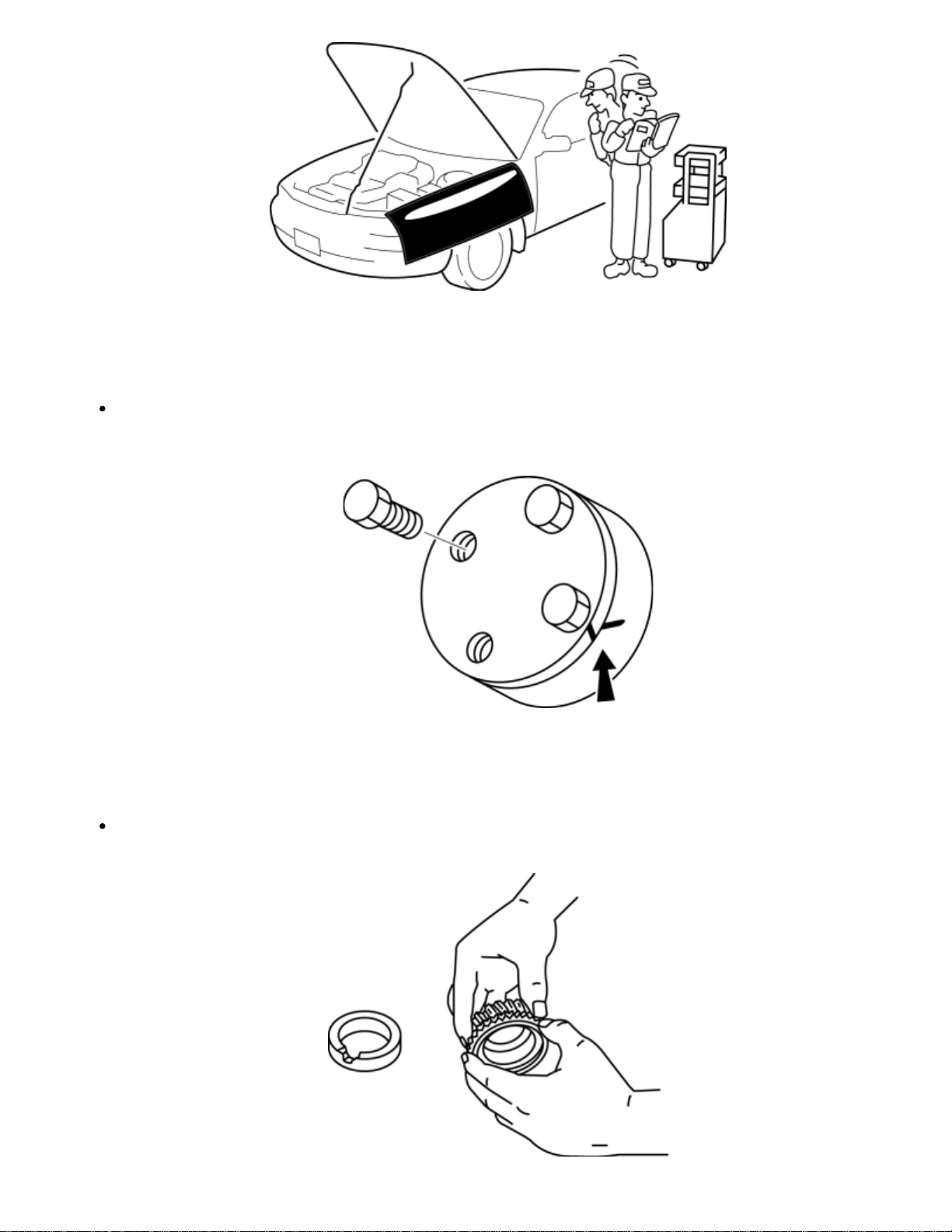
Disassembly
If the disassembly procedure is complex, requiring many parts to be disassembled, all
parts should be marked in a place that will not affect their performance or external
appearance, and identified so that reassembly can be performed easily and efficiently.
Inspection During Removal, Disassembly
When removed, each part should be carefully inspected for malfunction, deformation,
damage and other problems.
Page 28
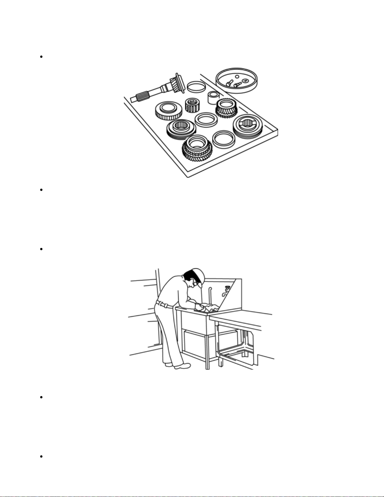
Arrangement of Parts
All disassembled parts should be carefully arranged for reassembly.
Be sure to separate or otherwise identify the parts to be replaced from those that will be
reused.
Cleaning of Parts
All parts to be reused should be carefully and thoroughly cleaned in the appropriate
method.
WARNING:
Using compressed air can cause dirt and other particles to fly out causing injury to the
eyes. Wear protective eye wear whenever using compressed air.
Reassembly
Standard values, such as torques and certain adjustments, must be strictly observed in the
reassembly of all parts.
Page 29
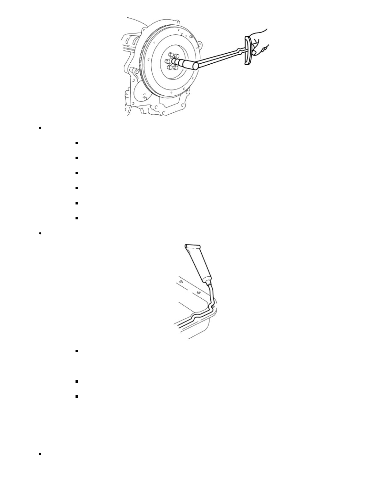
If removed, the following parts should be replaced with new ones:
Oil seals
Gaskets
O–rings
Lock washers
Cotter pins
Nylon nuts
Depending on location:
Adjustment
Use suitable gauges and testers when making adjustments.
Sealant and gaskets, or both, should be applied to specified locations.
When sealant is applied, parts should be installed before sealant hardens
to prevent leakage.
Oil should be applied to the moving components of parts.
Specified oil or grease should be applied at the prescribed locations (such
as oil seals) before reassembly.
Page 30
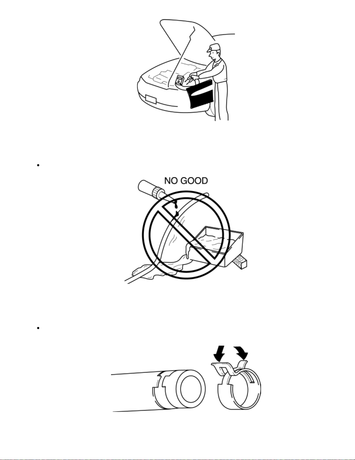
Rubber Parts and Tubing
Prevent gasoline or oil from getting on rubber parts or tubing.
Hose Clamps
When reinstalling, position the hose clamp in the original location on the hose and squeeze
the clamp lightly with large pliers to ensure a good fit.
Page 31
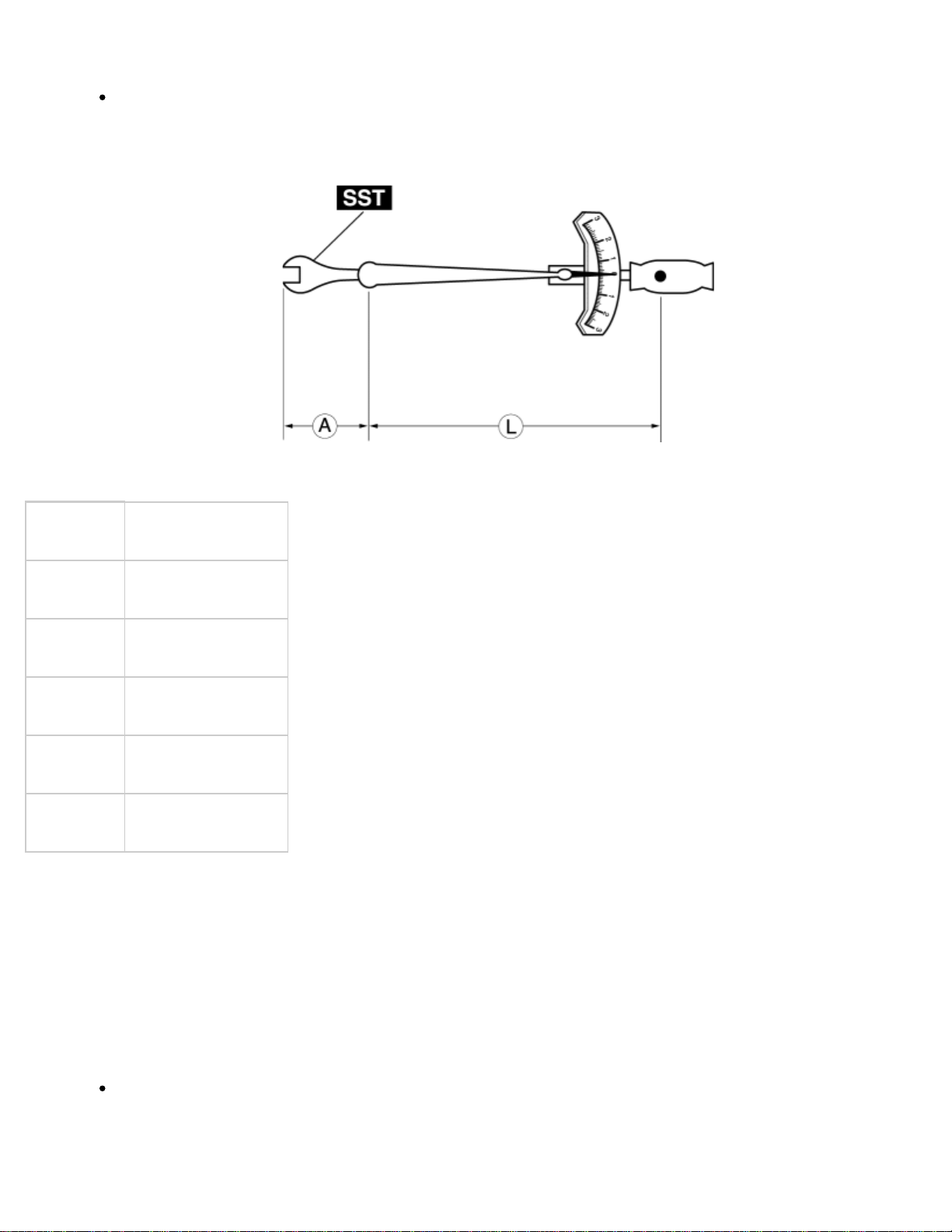
Torque Formulas
Torque Unit Formula
When using a torque wrench–SST or equivalent combination, the specified torque must be
recalculated due to the extra length that the SST or equivalent adds to the torque wrench.
Recalculate the torque by using the following formulas. Choose the formula that applies to
you.
N·m N·m × [L/(L+A)]
kgf·m kgf·m × [L/(L+A)]
kgf·cm kgf·cm × [L/(L+A)]
ft·lbf ft·lbf × [L/(L+A)]
in·lbf in·lbf × [L/(L+A)]
A
The length of the SST past the torque wrench drive.
L
The length of the torque wrench.
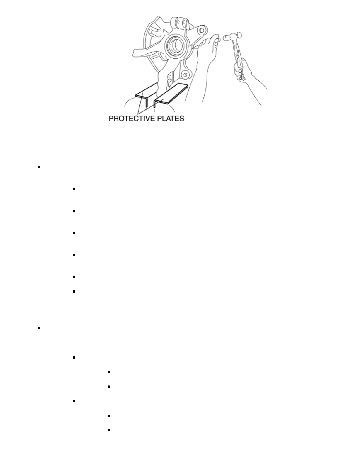
Vise
When using a vise, put protective plates in the jaws of the vise to prevent damage to
parts.
Page 32
Dynamometer
When inspecting and servicing the power train on the dynamometer or speedometer
tester, pay attention to the following:
NOTE:
Place a fan, preferably a vehicle–speed proportional type, in front of the
vehicle.
Make sure the vehicle is in a facility with an exhaust gas ventilation
system.
Since the rear bumper might deform from the heat, cool the rear with a
fan. (Surface of the bumper must be below 70 °C {158 °F} .)
Keep the area around the vehicle uncluttered so that heat does not build
up.
Watch the water temperature gauge and do not overheat the engine.
Avoid added load to the engine and maintain normal driving conditions as
much as possible.
When only the front or rear wheels are rotated on a chassis dynamometer or equivalent,
the ABS/DSC HU/CM determines that there is a malfunction in the ABS/DSC and illuminates
the following lights:
Vehicles with ABS
ABS warning light
Brake system warning light
Vehicles with DSC
ABS warning light
Brake system warning light
Page 33

DSC indicator light
If the above lights are illuminated, dismount the vehicle from the chassis dynamometer
and turn the ignition switch to the LOCK position. Then, turn the ignition switch back to
the ON position, run the vehicle at 10 km/h or more and verify that the warning lights
go out. In this case, a DTC will be stored in the memory. Clear the DTC from the memory
by following the memory clearing procedure [ABS]/[DSC] in the on-board diagnostic
system. (See
STABILITY CONTROL (DSC)])
< Previous Next >
ON-BOARD DIAGNOSIS [ABS])(See ON-BOARD DIAGNOSIS [DYNAMIC
Back to Top
© 2010 Mazda North American Operations, U.S.A.
Page 34
< Previous Next >
2011 - RX-8 - General Information
INSTALLATION OF RADIO SYSTEM
The control module and control unit have been designed with sufficient attention to radio wave
disturbances from the outside. However, observe the following precautions when installing the radio set to
the vehicle to prevent adverse effects on the control module and control unit.
Install the radio set and its antenna as far away as possible from the control module and
control unit.
The antenna feeder and power cable generate radio waves, therefore, keep them 100
mm {3.94 in} or more from the control module, control unit, and wiring harness. If the
antenna feeder and power cable cross over the wiring harness, place them perpendicular
to the wiring harness.
Do not install a high output radio set.
Do not use the control module and control unit power source for the radio set. In addition,
do not use the cigar lighter and accessory socket power source.
Do not attach the antenna feeder or wiring harness of the radio set to the wiring harness,
fuel pipe, or brake tube of the vehicle.
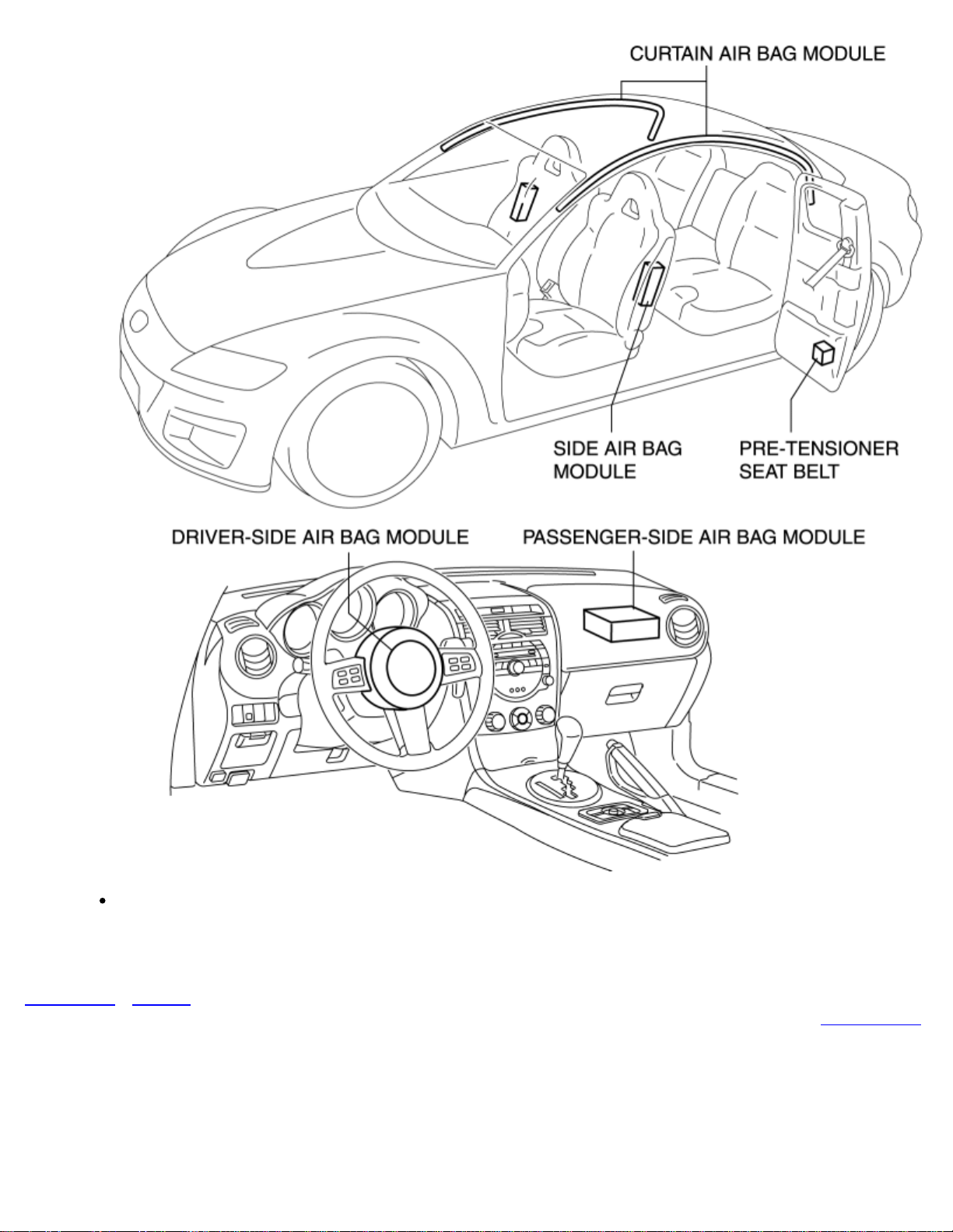
Do not install any radio set-related devices in the area where the air bag module deploys
to prevent a secondary accident if the air bag were to deploy.
Page 35
After installing the radio set, perform a test transmission with the engine idling to verify
that it does not affect engine control.
< Previous Next >
Back to Top
© 2010 Mazda North American Operations, U.S.A.
Page 36
< Previous Next >
2011 - RX-8 - General Information
ELECTRICAL SYSTEM
Electrical Parts
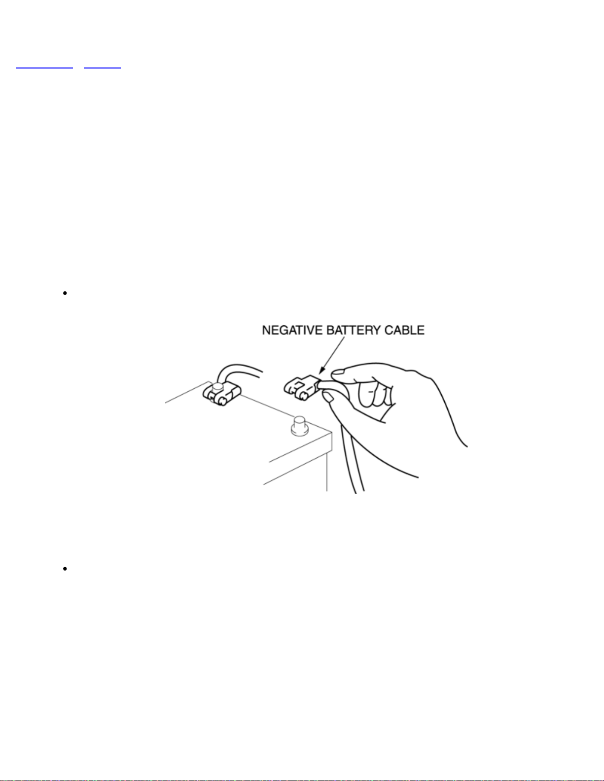
Battery cable
Before disconnecting connectors or removing electrical parts, disconnect the negative
battery cable.
Wiring Harness
To remove the wiring harness from the clip in the engine room, pry up the hook of the clip
using a flathead screwdriver.
Page 37
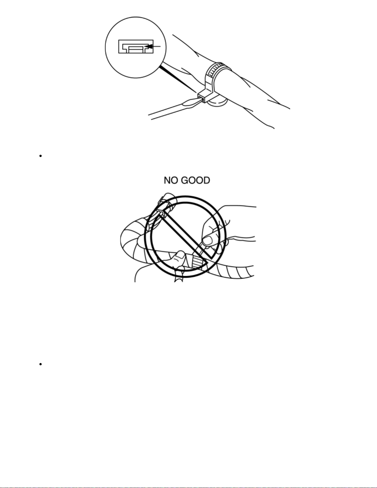
CAUTION:
Do not remove the harness protective tape. Otherwise, the wires could rub against the
body, which could result in water penetration and electrical shorting.
Connectors
Disconnecting connectors
When disconnecting connector, grasp the connectors, not the wires.
Page 38
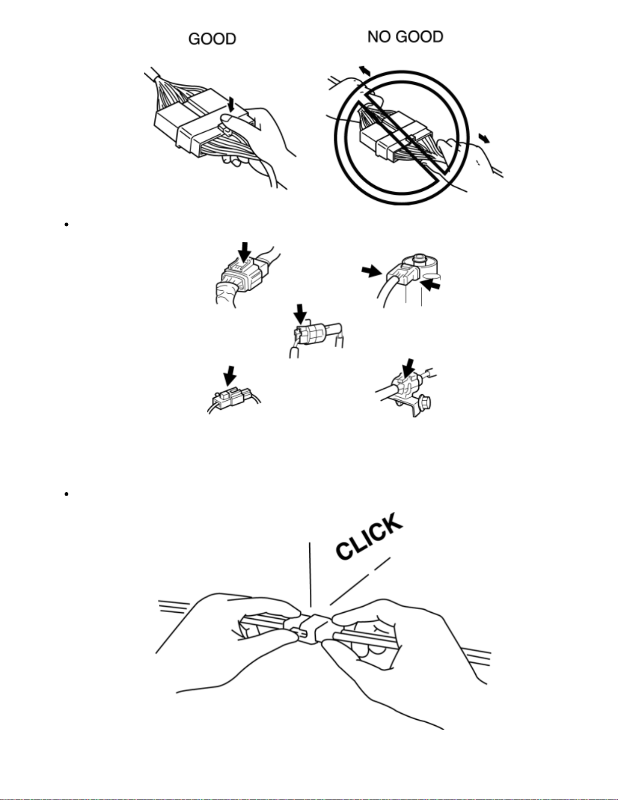
Connectors can be disconnected by pressing or pulling the lock lever as shown.
Locking connector
When locking connectors, listen for a click indicating they are securely locked.
Page 39
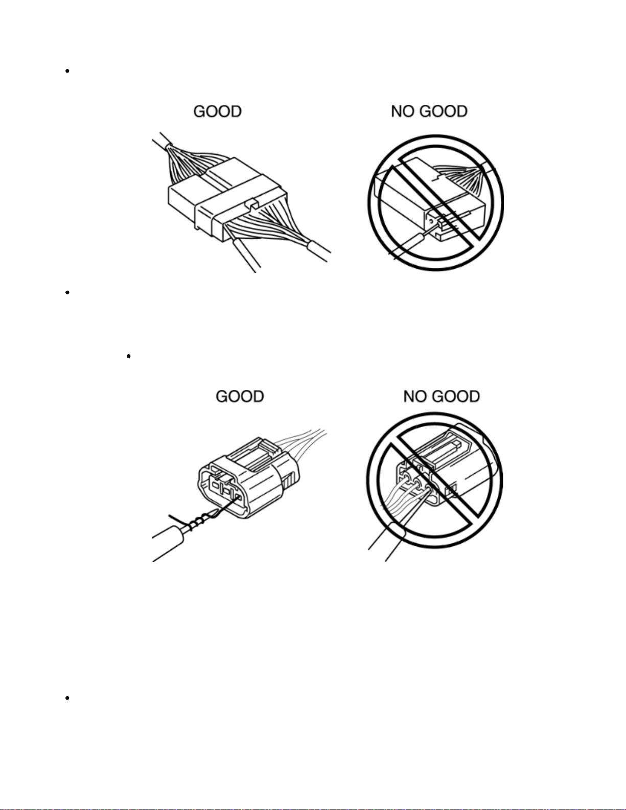
Inspection
When a tester is used to inspect for continuity or measuring voltage, insert the tester
probe from the wiring harness side.
Inspect the terminals of waterproof connectors from the connector side since they cannot
be accessed from the wiring harness side.
CAUTION:
Terminals
To prevent damage to the terminal, wrap a thin wire around the tester
probe before inserting into terminal.
Inspection
Pull lightly on individual wires to verify that they are secured in the terminal.
Page 40
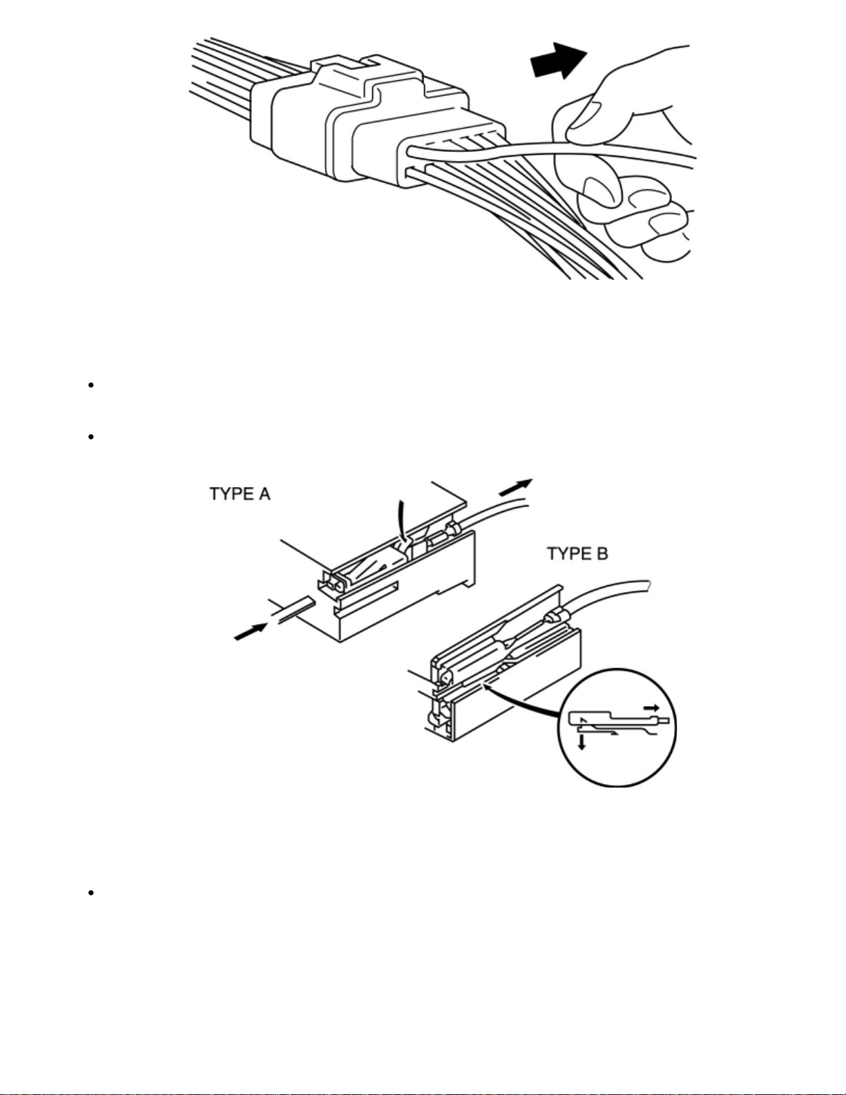
Replacement
Use the appropriate tools to remove a terminal as shown. When installing a terminal, be
sure to insert it until it locks securely.
Insert a thin piece of metal from the terminal side of the connector and with the terminal
locking tab pressed down, pull the terminal out from the connector.
Sensors, Switches, and Relays
Handle sensors, switches, and relays carefully. Do not drop them or strike them against
other objects.
Page 41
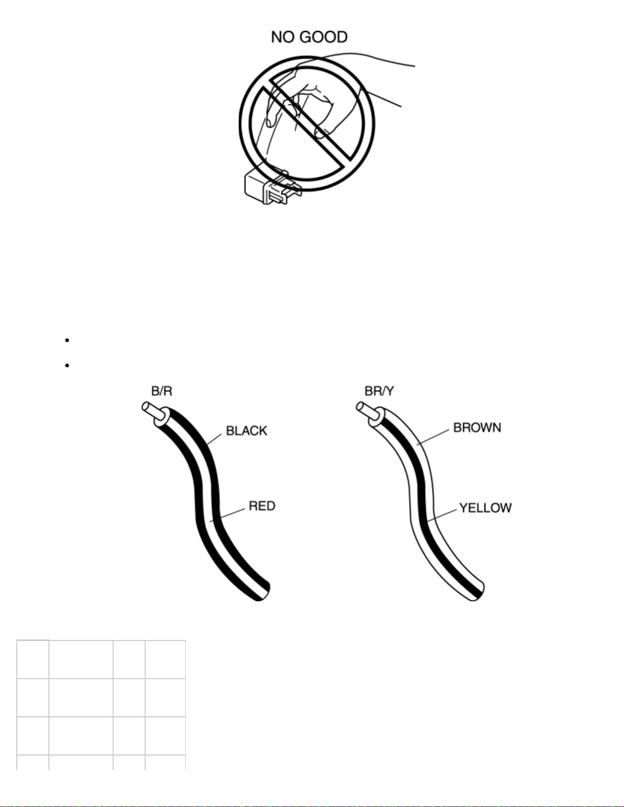
Wiring Harness
Wiring color codes
Two–color wires are indicated by a two–color code symbol.
The first letter indicates the base color of the wire and the second the color of the stripe.
CODE COLOR CODECOLOR
B Black O Orange
BR Brown P Pink
Page 42
G Green R Red
GY Gray V Violet
L Blue W White
LB Light Blue Y Yellow
LG Light Green – –
Fuse
Replacement
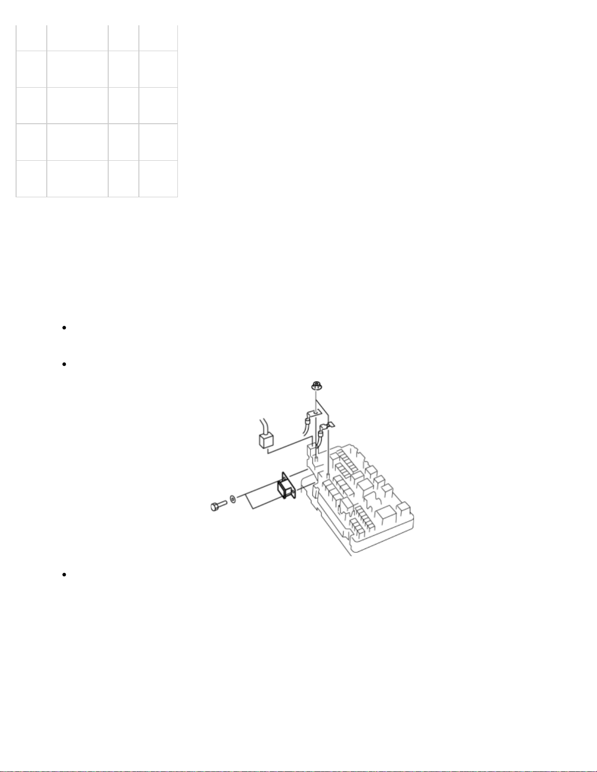
When replacing a fuse, be sure to replace it with one of the same capacity. If a fuse fails
again, the circuit probably has a short and the wiring should be inspected.
Be sure the negative battery terminal is disconnected before replacing a main fuse.
When replacing a pullout fuse, use the fuse puller.
Page 43
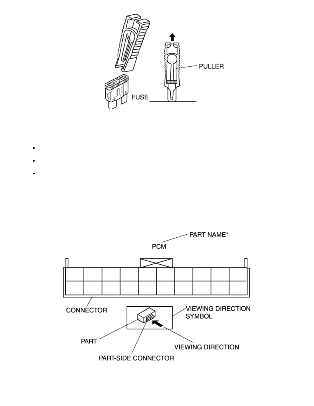
Direction of View for Connector
The viewing direction of connectors is indicated with a symbol.
The figures showing the viewing direction are the same as those used in Wiring Diagrams.
The viewing directions are shown in the following three ways:
Part- side connector
The viewing direction of part-side connectors is from the terminal side.
*
Part names are shown only when there are multiple connector drawings.
Page 44
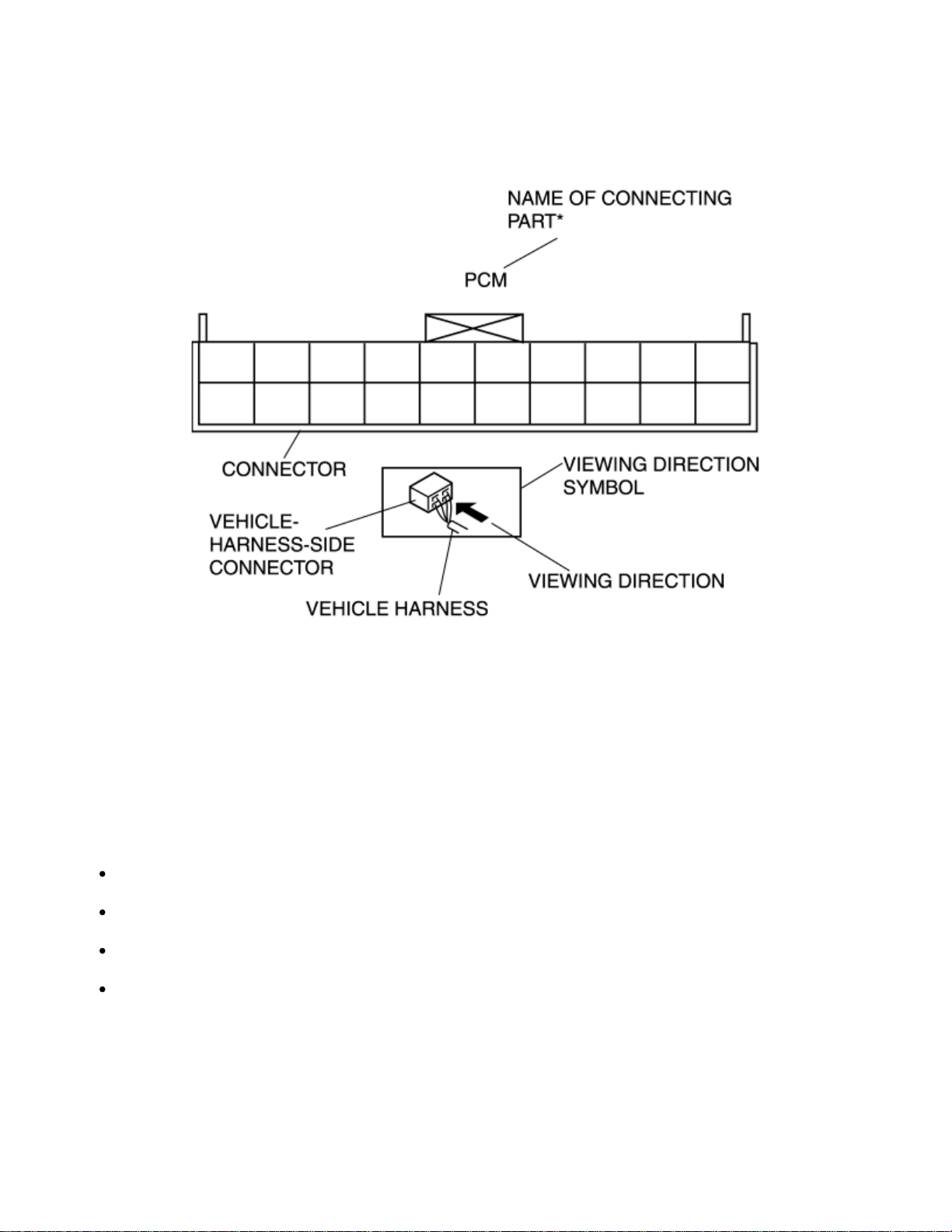
Vehicle harness-side connector
The viewing direction of vehicle harness-side connectors is from the harness side.
*
Part names are shown only when there are multiple connector drawings.
Other
When it is necessary to show the terminal side of vehicle harness-side connectors, such as the following
connectors, the viewing direction is from the terminal side.
Main fuse block and the main fuse block relays
Data link connector
Check connector
Relay box
Page 45
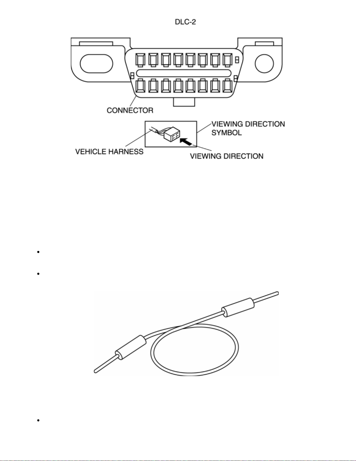
Electrical Troubleshooting Tools
Jumper wire
CAUTION:
Do not connect a jumper wire from the power source line to a body ground. This may
cause burning or other damage to wiring harnesses or electronic components.
A jumper wire is used to create a temporary circuit. Connect the jumper wire between the
terminals of a circuit to bypass a switch.
Voltmeter
The DC voltmeter is used to measure circuit voltage. A voltmeter with a range of 15 V or
more is used by connecting the positive (+) probe (red lead wire) to the point where
voltage will be measured and the negative (-) probe (black lead wire) to a body ground.
Page 46
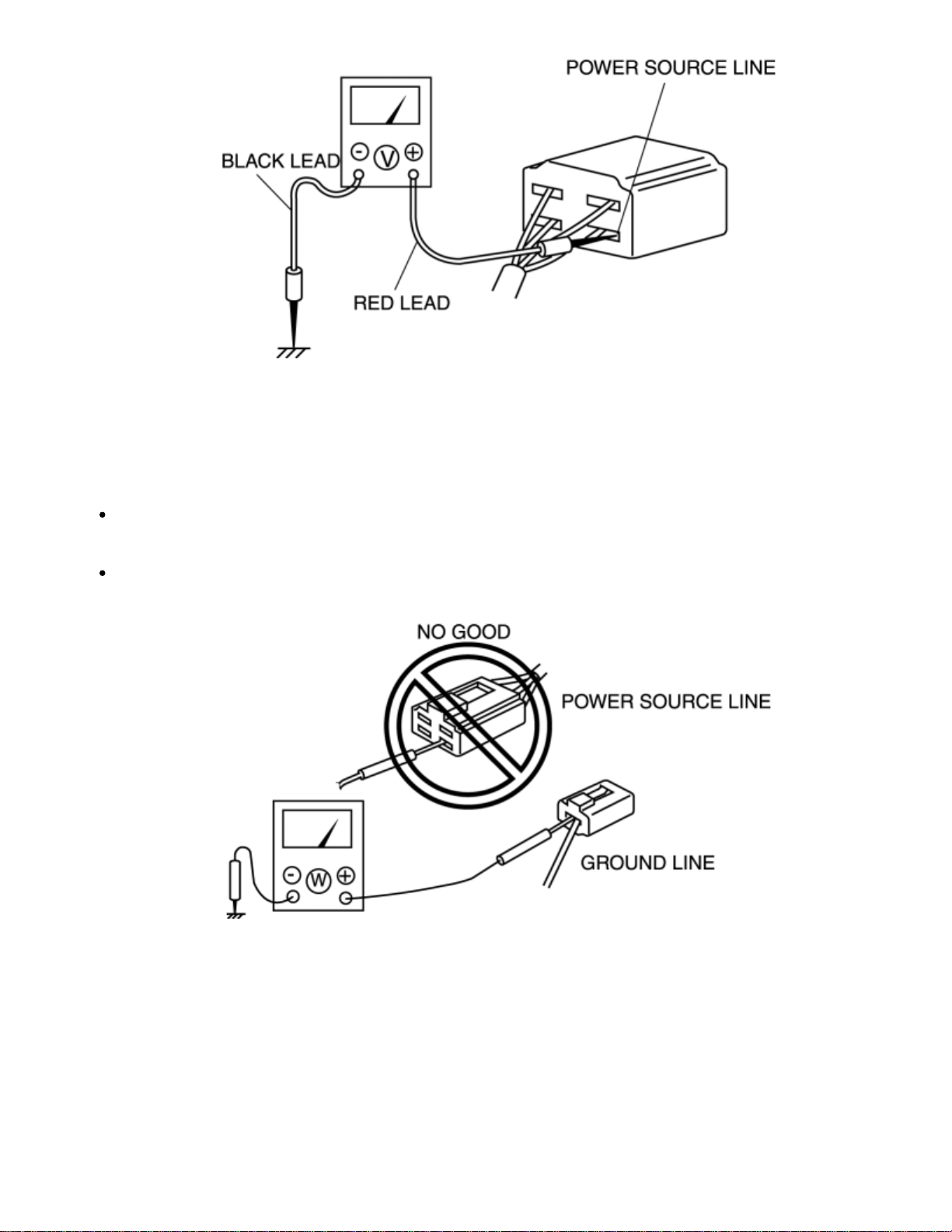
Ohmmeter
CAUTION:
Do not connect the ohmmeter to any circuit where voltage is applied. This will damage the
ohmmeter.
The ohmmeter is used to measure the resistance between two points in a circuit and to
inspect for continuity and short circuits.
Precautions Before Welding
A vehicle has various electrical parts. To protect the parts from excessive current generated when welding,
be sure to perform the following procedure.
1. Turn the ignition switch to the LOCK position.
2. Disconnect the battery cables.
Page 47
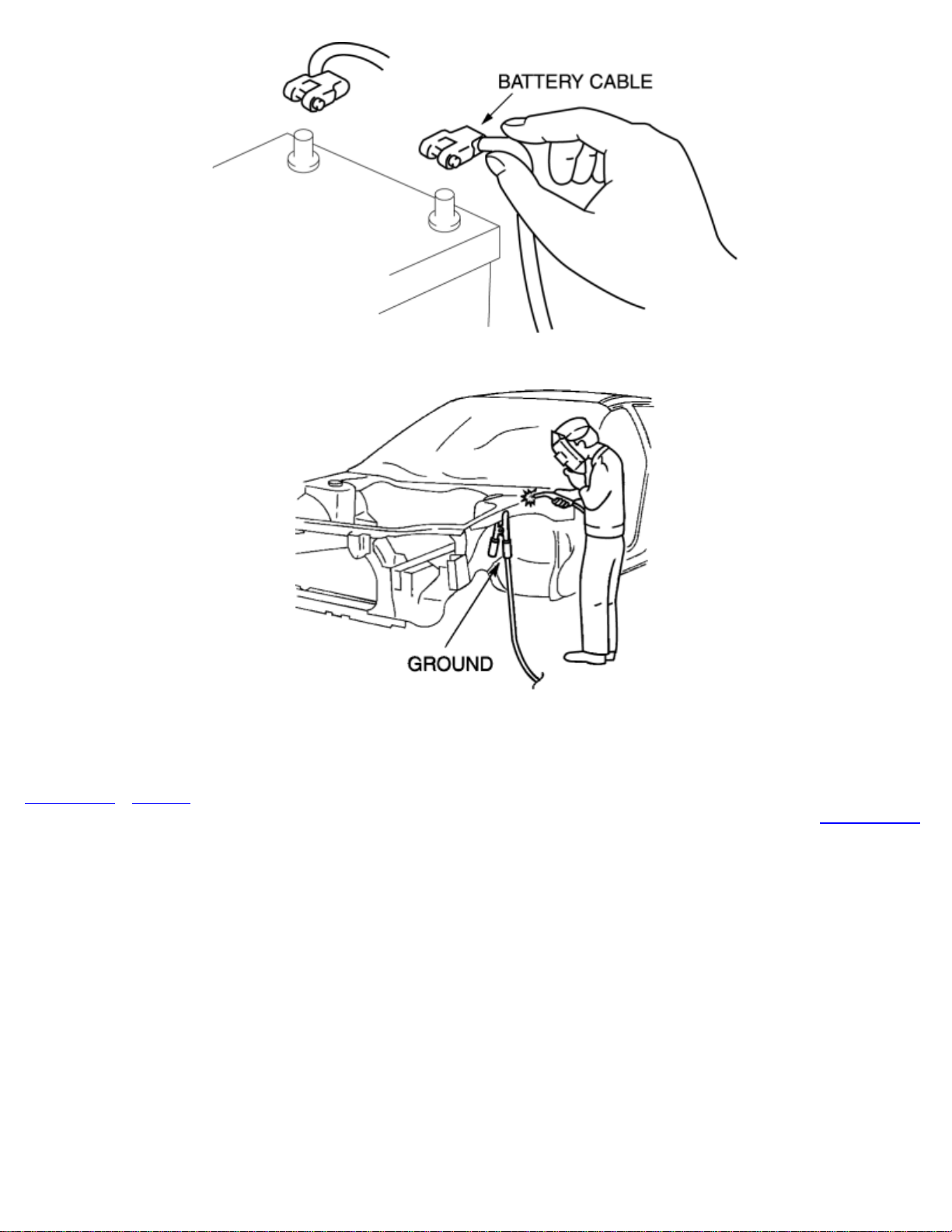
3. Securely connect the welding machine ground near the welding area.
4. Cover the peripheral parts of the welding area to protect them from weld spatter.
< Previous Next >
Back to Top
© 2010 Mazda North American Operations, U.S.A.
Page 48
< Previous Next >
2011 - RX-8 - General Information
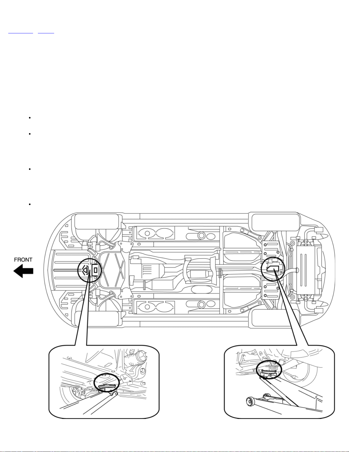
JACKING POSITIONS, VEHICLE LIFT (2 SUPPORTS) AND SAFETY STAND (RIGID RACK) POSITIONS
Jacking Positions
WARNING:
Improperly jacking a vehicle is dangerous. The vehicle can slip off the jack and cause serious injury. Use only the correct front
and rear jacking points and block the wheels.
Use safety stands to support the vehicle after it has been lifted.
Front
At the center of the front crossmember.
Rear
At the center of the differential.
Page 49
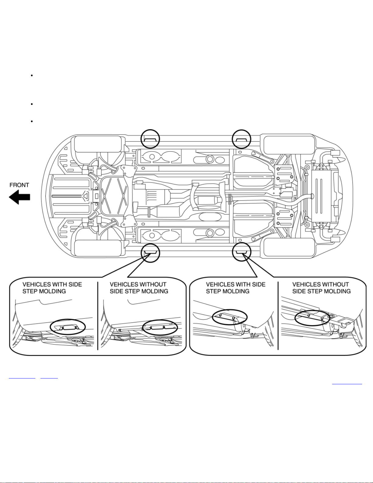
Vehicle Lift Positions
Front and rear
WARNING:
Unstably lifting a vehicle is dangerous. The vehicle can slip off the lift and cause serious injury and/or vehicle damage. Make
sure that the vehicle is on the lift horizontally by adjusting the height of support at the end of the arm of the lift.
CAUTION:
For vehicles with side step molding, be careful not to damage the side step molding by hitting it with auto-lift arms or a safety
stand.
Both sides of the vehicle, on side sills.
< Previous Next >
© 2010 Mazda North American Operations, U.S.A.
Back to Top
Page 50
< Previous Next >
2011 - RX-8 - General Information
TOWING
Towing
Proper lifting and towing are necessary to prevent damage to the vehicle. Government and
local laws must be followed.
A towed vehicle usually should have its drive wheels (rear wheels) off the ground. If
excessive damage or other conditions prevent this, use wheel dollies.
CAUTION:
CAUTION:
Do not tow the vehicle pointed forward with driving wheels on the ground. This may cause
internal damage to the transmission.
Page 51
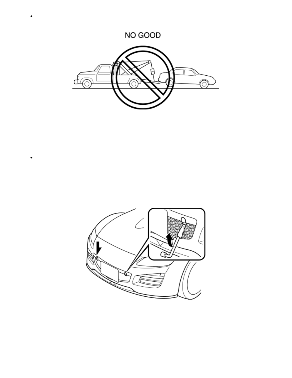
Do not tow with sling-type equipment. This could damage your vehicle. Use wheel-lift or
Tiedown
CAUTION:
flatbed equipment.
Do not use the front and rear tiedown eyelets for towing the vehicle. The have been
designed only for securing the vehicle to a transport vessel during shipping. Using the
eyelets for any other purpose could result in the vehicle being damaged.
1. Wrap the wheel brace with a soft cloth to prevent damage to a painted bumper, and open
the cap located on the front or rear bumper.
Front
Rear
Page 52
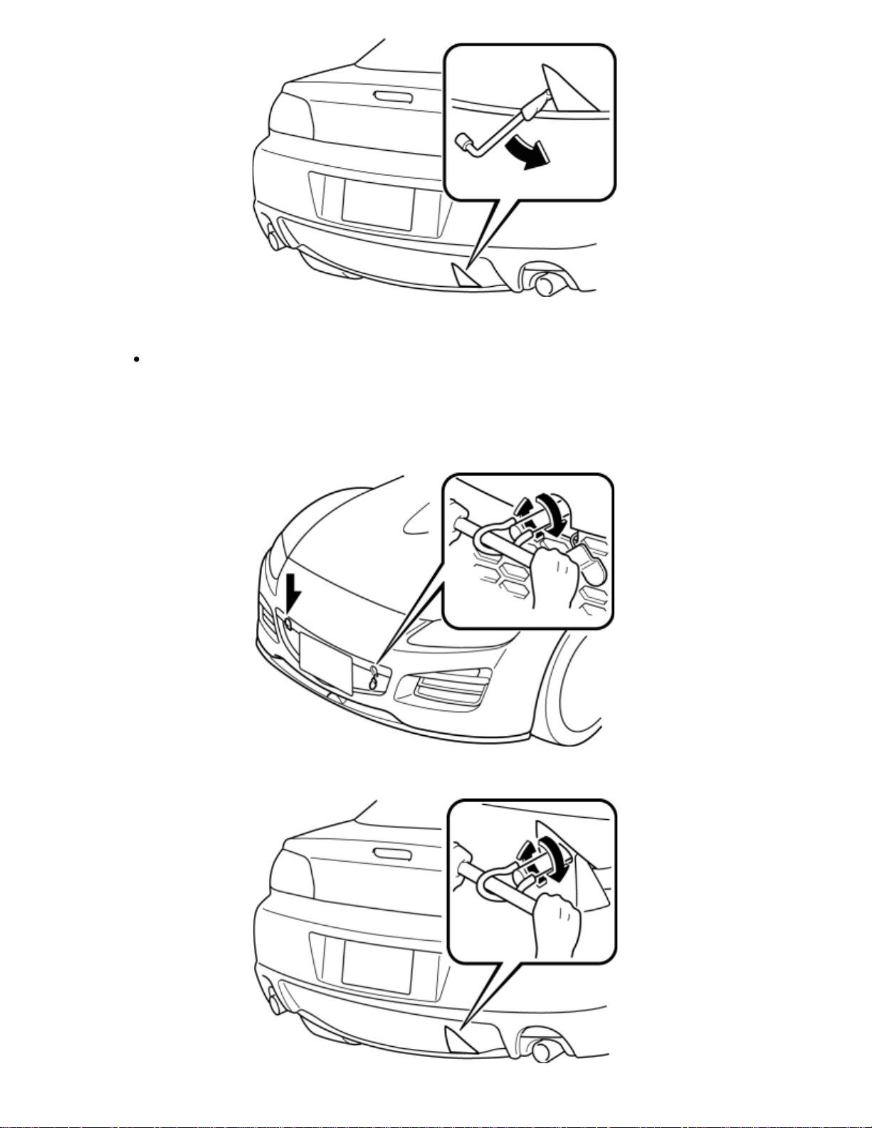
CAUTION:
The cap cannot be completely removed. Do not use excessive force as it may
damage the cap or scratch the painted bumper surface.
2. Securely install the tiedown eyelet using the wheel brace.
Front
Rear
Page 53
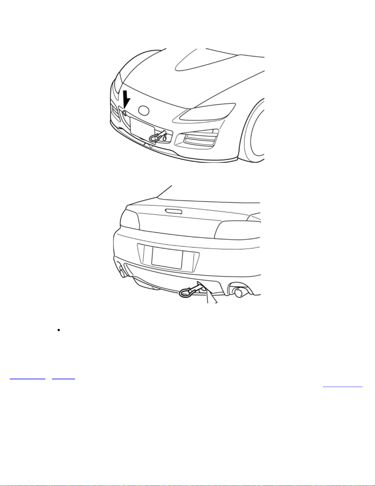
3. Hook the tying rope to the tiedown eyelet.
Front
Rear
CAUTION:
If the tiedown eyelet is not securely tightened, it may loosen or disengage from
the bumper when tying down the vehicle. Make sure that the tiedown eyelet is
securely tightened to the bumper.
< Previous Next >
Back to Top
© 2010 Mazda North American Operations, U.S.A.
Page 54
< Previous Next >
2011 - RX-8 - General Information
TIEDOWN HOOK
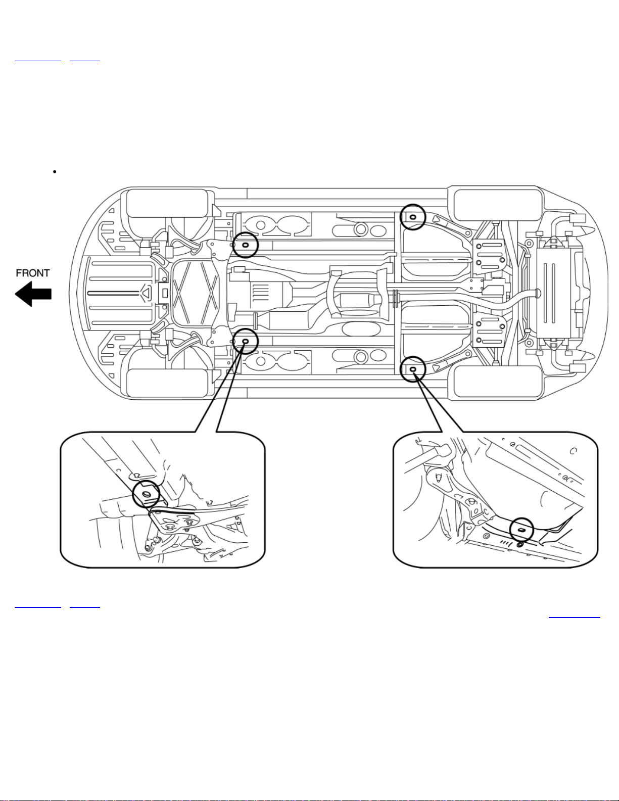
CAUTION:
Do not use the tiedown hook for towing the vehicle. Use it only for securing the vehicle.
< Previous Next >
Back to Top
© 2010 Mazda North American Operations, U.S.A.
Page 55
< Previous Next >
2011 - RX-8 - General Information
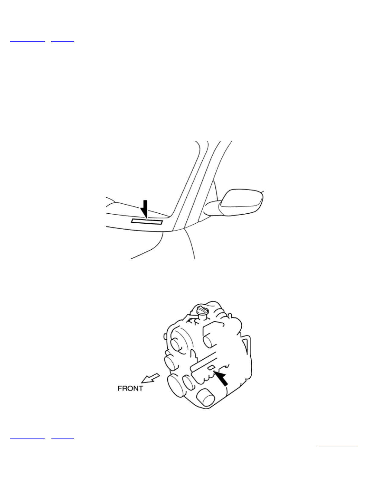
IDENTIFICATION NUMBER LOCATIONS
Vehicle Identification Number (VIN)
Engine Identification Number
< Previous Next >
© 2010 Mazda North American Operations, U.S.A.
Back to Top
Page 56
< Previous Next >
2011 - RX-8 - General Information
ABBREVIATIONS
AAS Active Adaptive Shift
ABS Antilock Brake System
ACC Accessories
ALC Auto Level Control
ALR Automatic Locking Retractor
APV Auxiliary Port Valve
AT Automatic Transmission
ATF Automatic Transmission Fluid
BTDC Before Top Dead Center
CAN Controller Area Network
CCM Comprehensive Component Monitor
CM Control Module
CPU Central Processing Unit
DC Drive Cycle
DSC Dynamic Stability Control
Page 57
EBD Electronic Brakeforce Distribution
ELR Emergency Locking Retractor
EPS Electric Power Steering
FFD Freeze Frame Data
F/P Fuel Pump
FP Front Primary
FS Front Secondary
GPS Global Positioning System
HF/TELHands-Free Telephone
HI High
HS High Speed
HU Hydraulic Unit
IDS Integrated Diagnostic Software
IG Ignition
INT Intermittent
KOEO Key ON Engine Off
KOER Key ON Engine Running
LCD Liquid Crystal Display
LED Light Emitting Diode
Page 58
LF Left Front
SST Special Service Tool
LH Left Hand
LO Low
L/R Leading Rear
LR Left Rear
M Motor
MAX Maximum
MS Middle Speed
MT Manual Transmission
OCV Oil Control Valve
PDS Portable Diagnostic Software
PID Parameter Identification
RAM Random Access Memory
RF Right Front
RH Right Hand
ROM Read Only Memory
RR Right Rear
SAS Sophisticated Air Bag Sensor
SAE Society of Automotive Engineers
Page 59
SW Switch
TCS Traction Control System
TFT Transmission Fluid Temperature
TNS Tail Number Side Lights
TPMS Tire Pressure Monitoring System
VDI Variable Dynamic Effect Intake
VFAD Variable Fresh Air Duct
1GR First Gear
2GR Second Gear
3GR Third Gear
4GR Fourth Gear
5GR Fifth Gear
6GR Sixth Gear
< Previous Next >
Back to Top
© 2010 Mazda North American Operations, U.S.A.
Page 60

< Previous Next >
2011 - RX-8 - General Information
PRE-DELIVERY INSPECTION
Pre–Delivery Inspection Table
Exterior
INSPECT and ADJUST, if necessary, the following items to specification:
□Glass, exterior bright metal and paint for damage
□Wheel lug nuts
□All weatherstrips for damage or detachment
□Tire pressures
□Headlight cleaner and fluid level (if equipped)
□Operation of hood release and lock
□Operation of trunk lid and fuel-filler lid opener
□Door operation and alignment including side door and back door
□Headlight aiming
INSTALL the following parts:
□Flap (front)
□Wheel caps or rings (if equipped)
Under hood—engine off
INSPECT and ADJUST, if necessary, the following items to specification:
□Fuel, engine coolant, and hydraulic lines, fittings, connections, and components for leaks
□Engine oil level
□Brake and clutch fluid level
□Windshield washer reservoir fluid level
□Manual transmission oil level
□Radiator coolant level and specific gravity
□Tightness of water hose clamps
□Tightness of battery terminals, electrolyte level and specific gravity
□Differential oil level
Interior
INSTALL the following items:
□Fuse for accessories
INSPECT the operations of the following items:
Page 61

□Seat controls (slide and recline) and headrests
□Folding rear seat
□Door locks, including childproof door locks
□Seat belts and warning system
□Ignition switch and steering lock
□Transmission range switch
□Warning buzzers
□Ignition key reminder alarm
□Air bag system using warning light
□Cruise control system (if equipped)
□Power door lock
□Shift–lock system (if equipped)
□Starter interlock
□All lights including warning, and indicator lights
□Horn, wipers, and washers
□Wiper blades performance
Clean wiper blades and windshield, if necessary
□Antenna
□Audio system
□Cigarette lighter and clock
□Power windows (if equipped)
□Heater, defroster, and air conditioner at various mode selections (if equipped)
INSPECT the following items:
□Presence of spare fuse
□Upholstery and interior finish
INSPECT and ADJUST, if necessary, the following items:
□Operation and fit of windows
□Pedal height and free play of clutch pedal
□Parking brake
Under hood—engine running at operating temperature
INSPECT the following items:
□Automatic transmission fluid level
□Operation of idle–up system for electrical load, air conditioner or power steering (if equipped)
□Ignition timing
□Idle speed
□Operation of throttle position sensor
On hoist
INSPECT the following items:
□Manual transmission oil level
□Underside fuel, coolant and hydraulic lines, fittings, connections, and components for leaks
□Tires for cuts or bruises
□Steering linkage, suspension, exhaust system, and all underside hardware for looseness or damage
Road test
INSPECT the following items:
□Brake operation
□Clutch operation
Page 62

□Steering control
□Operation of gauges
□Squeaks, rattles, and unusual noises
□Engine general performance
□Emergency locking retractors and automatic locking retractors
□Cruise control system (if equipped)
□Operation of meters and gauges, squeaks, rattles, and abnormal noises
After road test
INSPECT for necessary owner information materials, tools, and spare tire in vehicle
The following items must be completed just before delivery to your customer.
□Load test battery and charge if necessary (Load test result: Volts)
□Adjust tire pressure to specification (Specified tire pressure is indicated on the door label.)
□Clean outside of vehicle
□Install fuses for accessories
□Remove seat and cabin carpet protective covers
□Vacuum inside of vehicle
< Previous Next >
Back to Top
© 2010 Mazda North American Operations, U.S.A.
Page 63
< Previous
2011 - RX-8 - General Information
SCHEDULED MAINTENANCE
Scheduled Maintenance Table for U.S.A., CANADA, and Puerto Rico
Schedule 1 (Normal Driving Conditions) for USA
The vehicle is mainly operated where none of the "unique driving conditions" apply.
Number of months or kilometers (miles), whichever comes first
Months 6 12 18 24 30 36 42 48
Maintenance Interval
×1000 km 12 24 36 48 60 72 84 96
×1000 miles 7.5 15 22.5 30 37.5 45 52.5 60
ENGINE
Engine oil R R R R R R R R
Engine oil filter R R R R R R R R
Drive belts I I
COOLING SYSTEM
FL22 type
*1
Replace at first 192,000 km (120,000 miles) or
10 years;
after that, every 96,000 km (60,000 miles) or 5
years
Page 64
Engine coolant
Others Replace at first 96,000 km (60,000 miles) or 4
years;
after that, every 2 years
FUEL SYSTEM
Air cleaner element R
Fuel lines and hoses
*2
Hoses and tubes for emission
*2
I I
IGNITION SYSTEM
Spark plugs R
CHASSIS and BODY
Brake lines, hoses and connections I I
Disc brakes I I I I
Tire (Rotation) Rotate every 12,000 km (7,500 miles)
I
Flat tire repair kit
*3
Inspect annually
Steering operation and linkages I I
Front and rear suspension, ball joints and wheel bearing
I I
axial play
Manual transmission oil R
Rear differential oil R
Drive shaft dust boots I I
Page 65
Bolts and nuts on chassis and body T T
Exhaust system and heat shields
Inspect every 72,000 km (45,000 miles) or 5
years
All locks and hinges L L L L L L L L
AIR CONDITIONER SYSTEM
Cabin air filter
Chart symbols:
I: Inspect: Inspect and clean, repair, adjust, fill up or replace if necessary.
R: Replace
L: Lubricate
T: Tighten
Remarks
After the prescribed period, continue to follow the described maintenance at the
recommended intervals.
Refer below for a description of items marked* in the maintenance chart.
Replace every 40,000 km (25,000 miles) or 2
years
*1: Use FL22 type coolant in vehicles with the inscription "FL22" on the
radiator cap itself or the surrounding area. Use FL22 when replacing the
coolant.
*2: According to state/provincial and federal regulations, failure to
perform maintenance on these items will not void your emissions
warranties. However, Mazda recommends that all maintenance services be
performed at the recommended time or mileage/kilometer period to
ensure long-term reliability.
*3: Check the tire repair fluid expiration date every year when performing
the periodic maintenance. Replace the tire repair fluid bottle with new one
before the expiration date.
Schedule 2 CANADA, Puerto Rico, and (Unique Driving Conditions) for USA
Repeated short-distance driving
Page 66
Driving in dusty conditions
Driving with extended use of brakes
Driving in areas where salt or other corrosive materials are used
Driving on rough or muddy roads
Extended periods of idling or low-speed operation
Driving for long periods in cold temperatures or extremely humid climates
Driving in extremely hot conditions
Driving in mountainous conditions continually
Number of months or kilometers (miles), whichever comes first
Months 4 8 12 16 20 24 28 32 36 40 44 48
Maintenance Interval
×1000 km 8 16 24 32 40 48 56 64 72 80 88 96
×1000 miles 5 10 15 20 25 30 35 40 45 50 55 60
ENGINE
Puerto Rico Replace every 5,000 km (3,000 miles) or 3
months
Engine oil
Others R R R R R R R R R R R R
Engine oil filter R R R R R R R R R R R R
Drive belts I I
COOLING SYSTEM
Replace at first 192,000 km (120,000 miles) or
10 years;
FL22 type
*1
after that, every 96,000 km (60,000 miles) or 5
years
Engine coolant
Replace at first 96,000 km (60,000 miles) or 4
Page 67
Others
years;
after that, every 2 years
Engine coolant level I I I I I I I I I I I I
FUEL SYSTEM
Air cleaner element R
Fuel lines and hoses
*2
Hoses and tubes for emission
*2
I I
IGNITION SYSTEM
Spark plugs R
ELECTRICAL SYSTEM
Function of all lights I I I I I I I I I I I I
CHASSIS and BODY
Brake lines, hoses and connections I I
I
Brake and clutch fluid level I I I I I I I I I I I I
Brake fluid R R
Disc brakes I I I I
Tire (Rotation) Rotate every 8,000 km (5,000 miles)
Tire inflation pressure and tire wear I I I I I I I I I I I I
Flat tire repair kit
*3
Inspect annually
Steering operation and linkages I I
Page 68
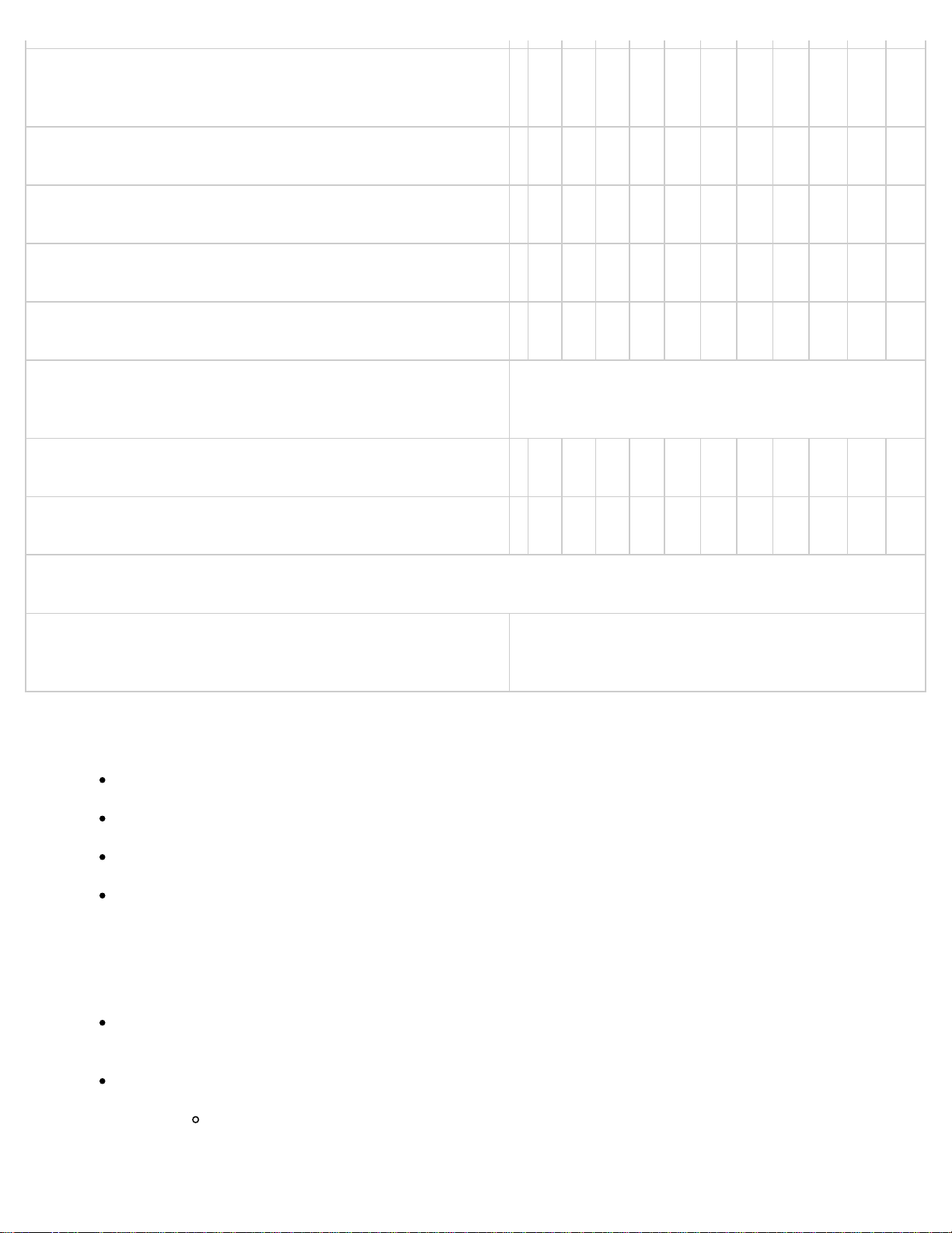
Front and rear suspension, ball joints and wheel bearing
I I
axial play
Manual transmission oil R R
Rear differential oil R R
Drive shaft dust boots I I
Bolts and nuts on chassis and body T T
Exhaust system and heat shields
Inspect every 72,000 km (45,000 miles) or 5
years
All locks and hinges L L L L L L L L L L L L
Washer fluid level I I I I I I I I I I I I
AIR CONDITIONER SYSTEM
Cabin air filter
Replace every 40,000 km (25,000 miles) or 2
years
Chart symbols:
I: Inspect: Inspect and clean, repair, adjust, fill up or replace if necessary.
R: Replace
Remarks
L: Lubricate
T: Tighten
After the prescribed period, continue to follow the described maintenance at the
recommended intervals.
Refer below for a description of items marked* in the maintenance chart.
*1: Use FL22 type coolant in vehicles with the inscription "FL22" on the
radiator cap itself or the surrounding area. Use FL22 when replacing the
coolant.
Page 69

< Previous
*2: According to state/provincial and federal regulations, failure to
perform maintenance on these items will not void your emissions
warranties. However, Mazda recommends that all maintenance services be
performed at the recommended time or mileage/kilometer period to
ensure long-term reliability.
*3: Check the tire repair fluid expiration date every year when performing
the periodic maintenance. Replace the tire repair fluid bottle with new one
before the expiration date.
Back to Top
© 2010 Mazda North American Operations, U.S.A.
Page 70
Workshop Manual - Engine
2011 - RX- 8
On- Board Diagnostics
ON-BOARD DIAGNOSTIC WIRING DIAGRAM [13B-MSP]
MONITORING SYSTEM AND CONTROL SYSTEM DEVICE RELATIONSHIP CHART [13B-MSP]
OBD-II PENDING TROUBLE CODE [13B-MSP]
OBD-II FREEZE FRAME DATA [13B-MSP]
OBD-II ON-BOARD SYSTEM READINESS TEST [13B-MSP]
OBD-II DIAGNOSTIC MONITORING TEST RESULTS [13B-MSP]
OBD-II READ/CLEAR DIAGNOSTIC TEST RESULTS [13B-MSP]
OBD-II PARAMETER IDENTIFICATION (PID) ACCESS [13B-MSP]
ON-BOARD DIAGNOSTIC TEST [13B-MSP]
AFTER REPAIR PROCEDURE [13B-MSP]
KOEO/KOER SELF TEST [13B-MSP]
OBD-II DRIVE MODE [13B-MSP]
DIAGNOSTIC MONITORING TEST RESULTS [13B-MSP]
DTC TABLE [13B-MSP]
DTC B1342 [13B-MSP]
DTC P0030 [13B-MSP]
DTC P0031 [13B-MSP]
DTC P0032 [13B-MSP]
DTC P0037 [13B-MSP]
DTC P0038 [13B-MSP]
DTC P0053 [13B-MSP]
DTC P0054 [13B-MSP]
DTC P0076 [13B-MSP]
DTC P0077 [13B-MSP]
DTC P0101 [13B-MSP]
DTC P0102 [13B-MSP]
DTC P0103 [13B-MSP]
DTC P0107 [13B-MSP]
DTC P0108 [13B-MSP]
DTC P0111 [13B-MSP]
DTC P0112 [13B-MSP]
DTC P0113 [13B-MSP]
DTC P0116 [13B-MSP]
DTC P0117 [13B-MSP]
DTC P0118 [13B-MSP]
DTC P0122 [13B-MSP]
DTC P0123 [13B-MSP]
Page 71
DTC P0125 [13B-MSP]
DTC P0126 [13B-MSP]
DTC P0130 [13B-MSP]
DTC P0131 [13B-MSP]
DTC P0132 [13B-MSP]
DTC P0133 [13B-MSP]
DTC P0134 [13B-MSP]
DTC P0137 [13B-MSP]
DTC P0138 [13B-MSP]
DTC P0139 [13B-MSP]
DTC P0171 [13B-MSP]
DTC P0172 [13B-MSP]
DTC P0222 [13B-MSP]
DTC P0223 [13B-MSP]
DTC P0300 [13B-MSP]
DTC P0301, P0302 [13B-MSP]
DTC P0327 [13B-MSP]
DTC P0328 [13B-MSP]
DTC P0332 [13B-MSP]
DTC P0333 [13B-MSP]
DTC P0335 [13B-MSP]
DTC P0336 [13B-MSP]
DTC P0410, P0411 [13B-MSP]
DTC P0420 [13B-MSP]
DTC P0441 [13B-MSP]
DTC P0442, P0455, P0456 [13B-MSP]
DTC P0443 [13B-MSP]
DTC P0446 [13B-MSP]
DTC P0461 [13B-MSP]
DTC P0462 [13B-MSP]
DTC P0463 [13B-MSP]
DTC P0480 [13B-MSP]
DTC P0481 [13B-MSP]
DTC P0482 [13B-MSP]
DTC P0500 [13B-MSP]
DTC P0505 [13B-MSP]
DTC P0506 [13B-MSP]
DTC P0507 [13B-MSP]
DTC P050A [13B-MSP]
DTC P0522 [13B-MSP]
DTC P0523 [13B-MSP]
DTC P0562 [13B-MSP]
DTC P0564 [13B-MSP]
DTC P0571 [13B-MSP]
DTC P0601 [13B-MSP]
DTC P0602 [13B-MSP]
DTC P0604 [13B-MSP]
DTC P0606 [13B-MSP]
DTC P0610 [13B-MSP]
DTC P0638 [13B-MSP]
DTC P0661 [13B-MSP]
DTC P0662 [13B-MSP]
DTC P0703 [13B-MSP]
DTC P0704 [13B-MSP]
DTC P0850 [13B-MSP]
DTC P1260 [13B-MSP]
DTC P1680 [13B-MSP]
Page 72
DTC P1681 [13B-MSP]
DTC P1682 [13B-MSP]
DTC P1683 [13B-MSP]
DTC P1684 [13B-MSP]
DTC P1685 [13B-MSP]
DTC P1686 [13B-MSP]
DTC P1687 [13B-MSP]
DTC P2004 [13B-MSP]
DTC P2005 [13B-MSP]
DTC P2006 [13B-MSP]
DTC P2007 [13B-MSP]
DTC P2009 [13B-MSP]
DTC P2010 [13B-MSP]
DTC P2067 [13B-MSP]
DTC P2068 [13B-MSP]
DTC P2070 [13B-MSP]
DTC P2071 [13B-MSP]
DTC P2096 [13B-MSP]
DTC P2097 [13B-MSP]
DTC P2101 [13B-MSP]
DTC P2107 [13B-MSP]
DTC P2108 [13B-MSP]
DTC P2109 [13B-MSP]
DTC P2112 [13B-MSP]
DTC P2119 [13B-MSP]
DTC P2122 [13B-MSP]
DTC P2123 [13B-MSP]
DTC P2127 [13B-MSP]
DTC P2128 [13B-MSP]
DTC P2135 [13B-MSP]
DTC P2138 [13B-MSP]
DTC P2195 [13B-MSP]
DTC P2196 [13B-MSP]
DTC P2299 [13B-MSP]
DTC P2257 [13B-MSP]
DTC P2258 [13B-MSP]
DTC P2259 [13B-MSP]
DTC P2260 [13B-MSP]
DTC P2270 [13B-MSP]
DTC P2271 [13B-MSP]
DTC P2401 [13B-MSP]
DTC P2402 [13B-MSP]
DTC P2404 [13B-MSP]
DTC P2405 [13B-MSP]
DTC P2407 [13B-MSP]
DTC P2502 [13B-MSP]
DTC P2503 [13B-MSP]
DTC P2504 [13B-MSP]
Symptom Troubleshooting
SYMPTOM TROUBLESHOOTING WIRING DIAGRAM [13B-MSP]
FOREWORD [13B-MSP]
SYMPTOM DIAGNOSTIC INDEX [13B-MSP]
QUICK DIAGNOSTIC CHART [13B-MSP]
NO.1 MELTING OF MAIN OR OTHER FUSES [13B-MSP]
Page 73
NO.2 MIL ILLUMINATES [13B-MSP]
NO.3 WILL NOT CRANK [13B-MSP]
NO.4 HARD TO START/LONG CRANK/ERRATIC START/ERRATIC CRANK [13B-MSP]
NO.5 ENGINE STALLS-AFTER START/AT IDLE [13B-MSP]
NO.6 CRANKS NORMALLY BUT WILL NOT START [13B-MSP]
NO.7 SLOW RETURN TO IDLE [13B-MSP]
NO.8 ENGINE RUNS ROUGH/ROLLING IDLE [13B-MSP]
NO.9 FAST IDLE/RUNS ON [13B-MSP]
NO.10 LOW IDLE/STALLS DURING DECELERATION [13B-MSP]
NO.11 ENGINE STALLS/QUITS, ENGINE RUNS ROUGH, MISSES, BUCK/JERK, HESITATION/STUMBLE,
SURGES [13B-MSP]
NO.12 LACK/LOSS OF POWER-ACCELERATION/CRUISE [13B-MSP]
NO.13 KNOCKING/PINGING/DETONATION-ACCELERATION/CRUISE [13B-MSP]
NO.14 POOR FUEL ECONOMY [13B-MSP]
NO.15 EMISSION COMPLIANCE [13B-MSP]
NO.16 HIGH OIL CONSUMPTION/LEAKAGE [13B-MSP]
NO.17 COOLING SYSTEM CONCERNS-OVERHEATING [13B-MSP]
NO.18 COOLING SYSTEM CONCERNS-RUNS COLD [13B-MSP]
NO.19 EXHAUST SMOKE [13B-MSP]
NO.20 FUEL ODOR (IN ENGINE COMPARTMENT) [13B-MSP]
NO.21 ENGINE NOISE [13B-MSP]
NO.22 VIBRATION CONCERNS (ENGINE) [13B-MSP]
NO.23 A/C DOES NOT WORK SUFFICIENTLY [13B-MSP]
NO.24 A/C IS ALWAYS ON OR A/C COMPRESSOR RUNS CONTINUOUSLY [13B-MSP]
NO.25 A/C IS NOT CUT OFF UNDER WIDE OPEN THROTTLE CONDITIONS [13B-MSP]
NO.26 EXHAUST SULPHUR SMELL [13B-MSP]
NO.27 FUEL REFILL CONCERNS [13B-MSP]
NO.28 FUEL FILLING SHUT OFF CONCERNS [13B-MSP]
NO.29 SPARK PLUG CONDITION [13B-MSP]
INTERMITTENT CONCERN TROUBLESHOOTING [13B-MSP]
ENGINE CONTROL SYSTEM OPERATION INSPECTION [13B-MSP]
Mechanical
ENGINE LOCATION INDEX [13B-MSP]
ENGINE TUNE-UP [13B-MSP]
ENGINE COVER REMOVAL/INSTALLATION [13B-MSP]
DRIVE BELT DEFLECTION/TENSION INSPECTION [13B-MSP]
DRIVE BELT REPLACEMENT [13B-MSP]
COMPRESSION INSPECTION [13B-MSP]
FRONT OIL SEAL REPLACEMENT [13B-MSP]
REAR OIL SEAL REPLACEMENT [13B-MSP]
ENGINE REMOVAL/INSTALLATION [13B-MSP]
ENGINE DISASSEMBLY/ASSEMBLY [13B-MSP]
Lubrication
LUBRICATION SYSTEM LOCATION INDEX [13B-MSP]
ENGINE OIL LEVEL INSPECTION [13B-MSP]
ENGINE OIL REPLACEMENT [13B-MSP]
OIL FILTER REPLACEMENT [13B-MSP]
OIL PRESSURE INSPECTION [13B-MSP]
OIL COOLER REMOVAL/INSTALLATION [13B-MSP]
OIL PAN REMOVAL/INSTALLATION [13B-MSP]
OIL PAN UPPER BLOCK REMOVAL/INSTALLATION [13B-MSP]
METERING OIL PUMP REMOVAL/INSTALLATION [13B-MSP]
Page 74
OIL NOZZLE REMOVAL/INSTALLATION [13B-MSP]
METERING OIL PUMP INSPECTION [13B-MSP]
OIL CONTROL VALVE (OCV) INSPECTION [13B-MSP]
OIL CONTROL VALVE (OCV) REMOVAL/INSTALLATION [13B-MSP]
Cooling System
COOLING SYSTEM LOCATION INDEX [13B-MSP]
COOLING SYSTEM SERVICE WARNINGS [13B-MSP]
ENGINE COOLANT LEVEL INSPECTION [13B-MSP]
ENGINE COOLANT PROTECTION INSPECTION [13B-MSP]
ENGINE COOLANT REPLACEMENT [13B-MSP]
ENGINE COOLANT LEAKAGE INSPECTION [13B-MSP]
COOLING SYSTEM CAP INSPECTION [13B-MSP]
COOLANT RESERVE TANK REMOVAL/INSTALLATION [13B-MSP]
RADIATOR REMOVAL/INSTALLATION [13B-MSP]
THERMOSTAT REMOVAL/INSTALLATION [13B-MSP]
THERMOSTAT INSPECTION [13B-MSP]
WATER PUMP REMOVAL/INSTALLATION [13B-MSP]
COOLING FAN COMPONENT REMOVAL/INSTALLATION [13B-MSP]
FAN MOTOR INSPECTION [13B-MSP]
In-Take Air System
INTAKE-AIR SYSTEM VACUUM HOSE ROUTING DIAGRAM [13B-MSP]
INTAKE-AIR SYSTEM LOCATION INDEX [13B-MSP]
INTAKE-AIR SYSTEM DIAGRAM [13B-MSP]
INTAKE MANIFOLD VACUUM INSPECTION [13B-MSP]
INTAKE-AIR SYSTEM REMOVAL/INSTALLATION [13B-MSP]
INTAKE-AIR SYSTEM INSPECTION [13B-MSP]
AIR CLEANER ELEMENT INSPECTION [13B-MSP]
THROTTLE BODY INSPECTION [13B-MSP]
INTAKE MANIFOLD REMOVAL/INSTALLATION [13B-MSP]
INTAKE MANIFOLD DISASSEMBLY/ASSEMBLY [13B-MSP]
SECONDARY SHUTTER VALVE (SSV) SOLENOID VALVE INSPECTION [13B-MSP]
SECONDARY SHUTTER VALVE (SSV) REMOVAL/INSTALLATION [13B-MSP]
SECONDARY SHUTTER VALVE (SSV) ACTUATOR INSPECTION [13B-MSP]
VARIABLE FRESH AIR DUCT (VFAD) SOLENOID VALVE INSPECTION [13B-MSP]
VARIABLE FRESH AIR DUCT (VFAD) ACTUATOR INSPECTION [13B-MSP]
VARIABLE DYNAMIC EFFECT INTAKE-AIR (VDI) SOLENOID VALVE INSPECTION [13B-MSP]
VARIABLE DYNAMIC EFFECT INTAKE-AIR (VDI) VALVE REMOVAL/INSTALLATION [13B-MSP]
VARIABLE DYNAMIC EFFECT INTAKE-AIR (VDI) ACTUATOR INSPECTION [13B-MSP]
AUXILIARY PORT VALVE (APV) MOTOR INSPECTION [13B-MSP]
CHECK VALVE (ONE-WAY) INSPECTION [13B-MSP]
ACCELERATOR PEDAL REMOVAL/INSTALLATION [13B-MSP]
VACUUM CHAMBER INSPECTION [13B-MSP]
Fuel System
FUEL SYSTEM LOCATION INDEX [13B-MSP]
FUEL SYSTEM DIAGRAM [13B-MSP]
BEFORE SERVICE PRECAUTION [13B-MSP]
AFTER SERVICE PRECAUTION [13B-MSP]
FUEL LINE PRESSURE INSPECTION [13B-MSP]
FUEL TANK REMOVAL/INSTALLATION [13B-MSP]
Page 75
FUEL TANK INSPECTION [13B-MSP]
NONRETURN VALVE INSPECTION [13B-MSP]
FUEL PUMP UNIT REMOVAL/INSTALLATION [13B-MSP]
FUEL PUMP UNIT DISASSEMBLY/ASSEMBLY [13B-MSP]
FUEL PUMP UNIT INSPECTION [13B-MSP]
FUEL PUMP RESISTOR REMOVAL/INSTALLATION [13B-MSP]
FUEL PUMP RESISTOR INSPECTION [13B-MSP]
QUICK RELEASE CONNECTOR REMOVAL/INSTALLATION [13B-MSP]
FUEL INJECTOR REMOVAL/INSTALLATION [13B-MSP]
FUEL INJECTOR INSPECTION [13B-MSP]
PULSATION DAMPER REMOVAL/INSTALLATION [13B-MSP]
PULSATION DAMPER INSPECTION [13B-MSP]
Exhaust System
EXHAUST SYSTEM INSPECTION [13B-MSP]
EXHAUST SYSTEM REMOVAL/INSTALLATION [13B-MSP]
EXHAUST MANIFOLD INSPECTION [13B-MSP]
Emissions System
EMISSION SYSTEM LOCATION INDEX [13B-MSP]
EMISSION SYSTEM DIAGRAM [13B-MSP]
FUEL-FILLER CAP INSPECTION [13B-MSP]
AIR FILTER INSPECTION [13B-MSP]
EVAPORATIVE EMISSION (EVAP) CONTROL SYSTEM REMOVAL/INSTALLATION [13B-MSP]
CHARCOAL CANISTER INSPECTION [13B-MSP]
EVAPORATIVE EMISSION (EVAP) SYSTEM LEAK DETECTION PUMP INSPECTION [13B-MSP]
PURGE SOLENOID VALVE INSPECTION [13B-MSP]
CATCH TANK INSPECTION [13B-MSP]
THREE-WAY CATALYTIC CONVERTER (TWC) INSPECTION [13B-MSP]
FUEL SHUT-OFF/ROLLOVER VALVE INSPECTION [13B-MSP]
QUICK RELEASE CONNECTOR (EMISSION SYSTEM) REMOVAL/INSTALLATION [13B-MSP]
EVAPORATIVE CHAMBER INSPECTION [13B-MSP]
SECONDARY AIR INJECTION (AIR) CONTROL VALVE REMOVAL/INSTALLATION [13B-MSP]
SECONDARY AIR INJECTION (AIR) CONTROL VALVE INSPECTION [13B-MSP]
SECONDARY AIR INJECTION (AIR) SOLENOID VALVE REMOVAL/INSTALLATION [13B-MSP]
SECONDARY AIR INJECTION (AIR) SOLENOID VALVE INSPECTION [13B-MSP]
SECONDARY AIR INJECTION (AIR) PUMP REMOVAL/INSTALLATION [13B-MSP]
SECONDARY AIR INJECTION (AIR) PUMP INSPECTION [13B-MSP]
Charging System
CHARGING SYSTEM LOCATION INDEX [13B-MSP]
BATTERY REMOVAL/INSTALLATION [13B-MSP]
BATTERY INSPECTION [13B-MSP]
BATTERY RECHARGING [13B-MSP]
GENERATOR REMOVAL/INSTALLATION [13B-MSP]
GENERATOR INSPECTION [13B-MSP]
GENERATOR DISASSEMBLY/ASSEMBLY [13B-MSP]
Ignition System
IGNITION SYSTEM LOCATION INDEX [13B-MSP]
IGNITION COIL REMOVAL/INSTALLATION [13B-MSP]
Page 76
IGNITION COIL INSPECTION [13B-MSP]
SPARK PLUG REMOVAL/INSTALLATION [13B-MSP]
SPARK PLUG INSPECTION [13B-MSP]
HIGH-TENSION LEAD REMOVAL/INSTALLATION [13B-MSP]
HIGH-TENSION LEAD INSPECTION [13B-MSP]
Starting System
STARTING SYSTEM LOCATION INDEX [13B-MSP]
STARTER REMOVAL/INSTALLATION [13B-MSP]
STARTER INSPECTION [13B-MSP]
STARTER DISASSEMBLY/ASSEMBLY [13B-MSP]
STARTER INTERLOCK SWITCH INSPECTION [13B-MSP]
Cruise Control System
CRUISE CONTROL SWITCH INSPECTION [13B-MSP]
Control System
CONTROL SYSTEM LOCATION INDEX [13B-MSP]
CONTROL SYSTEM DIAGRAM [13B-MSP]
CONTROL SYSTEM WIRING DIAGRAM [13B-MSP]
PCM REMOVAL/INSTALLATION [13B-MSP]
PCM INSPECTION [13B-MSP]
PCM CONFIGURATION [13B-MSP]
CLUTCH PEDAL POSITION (CPP) SWITCH INSPECTION [13B-MSP]
NEUTRAL SWITCH INSPECTION [13B-MSP]
AUXILIARY PORT VALVE (APV) POSITION SENSOR REMOVAL/INSTALLATION [13B-MSP]
AUXILIARY PORT VALVE (APV) POSITION SENSOR INSPECTION [13B-MSP]
SECONDARY SHUTTER VALVE (SSV) SWITCH INSPECTION [13B-MSP]
SECONDARY SHUTTER VALVE (SSV) SWITCH REMOVAL/INSTALLATION [13B-MSP]
ENGINE COOLANT TEMPERATURE (ECT) SENSOR REMOVAL/INSTALLATION [13B-MSP]
ENGINE COOLANT TEMPERATURE (ECT) SENSOR INSPECTION [13B-MSP]
MASS AIR FLOW (MAF)/INTAKE AIR TEMPERATURE (IAT) SENSOR REMOVAL/INSTALLATION [13B-MSP]
MASS AIR FLOW (MAF) SENSOR INSPECTION [13B-MSP]
INTAKE AIR TEMPERATURE (IAT) SENSOR INSPECTION [13B-MSP]
BAROMETRIC PRESSURE (BARO) SENSOR INSPECTION [13B-MSP]
THROTTLE POSITION (TP) SENSOR INSPECTION [13B-MSP]
ACCELERATOR PEDAL POSITION (APP) SENSOR INSPECTION [13B-MSP]
AIR FUEL RATIO (A/F) SENSOR REMOVAL/INSTALLATION [13B-MSP]
AIR FUEL RATIO (A/F) SENSOR INSPECTION [13B-MSP]
HEATED OXYGEN SENSOR (HO2S) REMOVAL/INSTALLATION [13B-MSP]
HEATED OXYGEN SENSOR (HO2S) INSPECTION [13B-MSP]
KNOCK SENSOR (KS) REMOVAL/INSTALLATION [13B-MSP]
KNOCK SENSOR (KS) INSPECTION [13B-MSP]
ECCENTRIC SHAFT POSITION PLATE REMOVAL/INSTALLATION [13B-MSP]
ECCENTRIC SHAFT POSITION SENSOR INSPECTION [13B-MSP]
ECCENTRIC SHAFT POSITION PLATE INSPECTION [13B-MSP]
ECCENTRIC SHAFT POSITION SENSOR REMOVAL/INSTALLATION [13B-MSP]
PCM TEMPERATURE SENSOR INSPECTION [13B-MSP]
OIL PRESSURE SENSOR REMOVAL/INSTALLATION [13B-MSP]
OIL PRESSURE SENSOR INSPECTION [13B-MSP]
METERING OIL PUMP DRIVER REMOVAL/INSTALLATION [13B-MSP]
METERING OIL PUMP DRIVER INSPECTION [13B-MSP]
Page 77

Technical Data
ENGINE TECHNICAL DATA [13B-MSP]
Maintenance/Service Tools
ENGINE SST [13B-MSP]
Page 78
< Previous Next >
2011 - RX-8 - Engine
DTC P0441 [13B-MSP]
DTC P0441 EVAP system incorrect purge flow
The PCM monitors the purge line vacuum, when the following conditions are
met. If the vacuum between the charcoal canister and the intake manifold
does not reach the specification, the PCM determines that the EVAP system
purge flow is incorrect.
MONITORING CONDITIONS
Vehicle speed: 70.1—130 km/h {43.5—80.8 mph}
DETECTION
CONDITION
Engine speed: 1,200—4,000 rpm
Throttle valve opening angle: 10.2—27.7 % (changes by
engine speed)
Diagnostic support note
This is an intermittent monitor (EVAP system).
The MIL illuminates if the PCM detects the above malfunction condition in
two consecutive drive cycles or in one drive cycle while the DTC for the same
malfunction has been stored in the PCM.
PENDING CODE is available if the PCM detects the above malfunction
condition during the first drive cycle.
FREEZE FRAME DATA (Mode 2/Mode 12) is available.
The DTC is stored in the PCM memory.
Blockage in EVAP system
EVAP hose damaged or loose
POSSIBLE
EVAP pipe damaged
Catch tank malfunction
Charcoal canister malfunction
Page 79
CAUSE
Purge solenoid valve malfunction
Diagnostic procedure
STEP INSPECTION ACTION
VERIFY FREEZE FRAME DATA (MODE 12) AND
1
DIAGNOSTIC MONITORING TEST RESULTS HAVE
BEEN RECORDED
Have the FREEZE FRAME DATA (Mode 12)
and DIAGNOSTIC MONITORING TEST
RESULTS (EVAP system related) been
recorded?
Leakage in EVAP system
Evaporative emission system leak detection pump malfunction
Fuel pump unit poor seal
PCM malfunction
YesGo to the next step.
No Record the FREEZE FRAME DATA
(Mode 12) and DIAGNOSTIC
MONITORING TEST RESULTS on the
repair order, then go to the next step.
VERIFY RELATED REPAIR INFORMATION
2
AVAILABILITY
Verify related Service Bulletins and/or online repair information availability.
Is any related repair information
available?
VERIFY RELATED PENDING CODE OR STORED DTC
3
Turn the ignition switch off, then to the
ON position (engine off).
Verify the related PENDING CODE or
stored DTCs.
Is the DTC P0443 present?
DETERMINE IF THERE IS BLOCKAGE
4
Clear the DTC from the PCM memory
using the M-MDS.
(See AFTER REPAIR PROCEDURE [13B-
MSP].)
YesPerform repair or diagnosis according
to the available repair information.
If the vehicle is not
repaired, go to the
next step.
No Go to the next step.
YesGo to the DTC P0443 inspection.
DTC P0443 [13B-MSP].)
(See
No Go to the next step.
YesGo to Step 6.
No Go to the next step.
Perform the KOER self test.
KOEO/KOER SELF TEST [13B-MSP].)
(See
Page 80
Is the DTC P0441 present?
INSPECT IF MALFUNCTION IS BLOCKAGE OR
5
LEAKAGE IN PURGE SOLENOID VALVE
NOTE:
YesReplace the purge solenoid valve, then
go to Step 12.
Carefully handle the evaporative system
when disconnecting and connecting
hoses. Do not use any lubricant around
the system. Foreign material can cause a
system malfunction.
Remove the purge solenoid valve and cool
it down in a refrigerator for 1 hour.
Install the purge solenoid valve and
perform the KOER self test using the MMDS.
(See
KOEO/KOER SELF TEST [13B-MSP].)
Is the DTC P0441 present?
INSPECT FOR LOCATION OF BLOCKAGE
6
Apply vacuum to the following parts using
a vacuum pump.
Verify that the system does not hold
vacuum at the following locations:
Hoses and pipes between
intake manifold and
charcoal canister
No Go to Step 7.
YesRepair or replace the malfunctioning
part according to the inspection results,
then go to Step 12.
No Replace the purge solenoid valve, then
go to Step 12.
Catch tank
Charcoal canister
Is there any blockage?
DETERMINE LEAKAGE EXISTENCE
7
Perform the Evaporative Emission (EVAP)
System Leak Inspection.
(See ENGINE CONTROL SYSTEM
OPERATION INSPECTION [13B-MSP].)
Is the DTC P0442 recorded?
INSPECT IF PURGE SOLENOID VALVE IS STUCK
8
OPEN
Inspect whether the purge solenoid valve
is stuck open.
YesGo to the next step.
No Go to Step 12.
YesGo to the next step.
No Replace the purge solenoid valve, then
Page 81
(See PURGE SOLENOID VALVE
go to Step 12.
INSPECTION [13B-MSP].)
Is the purge solenoid valve normal?
INSPECT FOR LOCATION OF LEAKAGE
9
Inspect the following for leakage using
the evaporative leak detector.
Between purge solenoid
valve and check valve
Between check valve and
charcoal canister
Is there any leakage?
INSPECT EVAP SYSTEM LEAK DETECTION PUMP
10
NOTE:
YesRepair or replace the malfunctioning
part according to the inspection results,
then go to Step 12.
No Go to the next step.
YesGo to the next step.
Be careful to not apply a shock to the
evaporative system leak detection pump,
otherwise the results of the leak
inspection could be incorrect.
Connect all disconnected connectors and
hoses.
Place a clamp on the evaporative system
leak detection pump hose between the
evaporative system leak detection pump
and the air filter.
Perform the Evaporative Emission (EVAP)
System Leak Inspection.
(See ENGINE CONTROL SYSTEM
OPERATION INSPECTION [13B-MSP].)
Is the DTC P2404 recorded?
INSPECT FUEL PUMP UNIT INSTALLATION
11
Remove the fuel tank.
No Replace the evaporative system leak
detection pump, then go to Step 13.
YesRepair or replace the fuel tank or
sealing, then go to the next step.
Visually inspect for damage, insufficient
sealing or a poorly installed pump unit.
Is there any malfunction?
PERFORM KOER SELF TEST TO DETERMINE OTHER
12
RELATED MALFUNCTION OTHER THAN BLOCKAGE
LOCATION
NOTE:
No Go to the next step.
YesBlockage still exists.
Locate blockage position and repair,
then go to the next step.
Page 82
Carefully handle the evaporative system
when disconnecting and connecting
hoses. Do not use any lubricant around
the system. Foreign material can cause a
system malfunction.
Connect all disconnected connectors and
hoses.
Perform the KOER self test.
KOEO/KOER SELF TEST [13B-MSP].)
(See
Is the DTC P0441 still recorded?
PERFORM LEAK INSPECTION
13
Connect all disconnected connectors and
hoses.
Perform the Evaporative Emission (EVAP)
System Leak Inspection.
(See ENGINE CONTROL SYSTEM
OPERATION INSPECTION [13B-MSP].)
No Go to the next step.
YesLeakage still exists.
Locate leak the point and repair, then
go to the next step.
No Go to the next step.
Does the test result fail (red light turns
on)?
VERIFY TROUBLESHOOTING OF DTC P0441
14
COMPLETED
Start the engine and let it idle.
Clear the DTC from the PCM memory
using the M-MDS.
(See AFTER REPAIR PROCEDURE [13B-
MSP].)
Turn the ignition switch off.
Perform the KOER self test.
KOEO/KOER SELF TEST [13B-MSP].)
(See
Is the PENDING CODE for this DTC
present?
VERIFY AFTER REPAIR PROCEDURE
15
Perform the “AFTER REPAIR
PROCEDURE”.
YesReplace the PCM, then go to the next
step.
(See PCM REMOVAL/INSTALLATION
[13B-MSP].)
No Go to the next step.
YesGo to the applicable DTC inspection.
DTC TABLE [13B-MSP].)
(See
(See AFTER REPAIR PROCEDURE [13B-
MSP].)
No DTC troubleshooting completed.
Page 83

Are any DTCs present?
< Previous Next >
Back to Top
© 2011 Mazda North American Operations, U.S.A.
Page 84
< Previous Next >
2011 - RX-8 - Engine
DTC P2005 [13B- MSP]
DTC P2005 APV stuck open (No.2)
The PCM monitors the input voltage from the APV position sensor No.2 when the APV is
closed. If the input voltage is more than 1.0 V, the PCM determines that the APV is
stuck open.
Diagnostic support note
This is a continuous monitor (CCM).
DETECTION
CONDITION
POSSIBLE
CAUSE
The MIL illuminates if the PCM detects the above malfunction condition in two
consecutive drive cycles or in one drive cycle while the DTC for the same malfunction
has been stored in the PCM.
PENDING CODE is available if the PCM detects the above malfunction condition during
the first drive cycle.
FREEZE FRAME DATA (Mode 2/Mode 12) is available.
The DTC is stored in the PCM memory.
APV control malfunction
APV motor malfunction
APV position sensor No.2 connector or terminals malfunction
APV position sensor No.2 malfunction
PCM connector or terminals malfunction
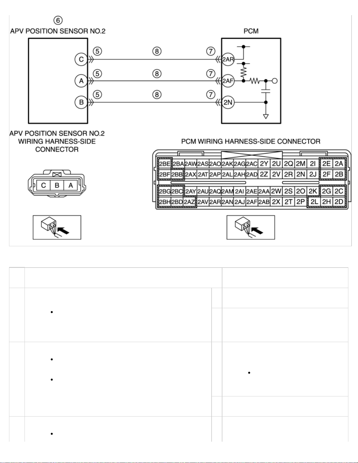
Open circuit in wiring harness between APV position sensor No.2 terminal C and PCM
terminal 2AR
Open circuit in wiring harness between APV position sensor No.2 terminal A and PCM
terminal 2AF
Open circuit in wiring harness between APV position sensor No.2 terminal B and PCM
terminal 2N
PCM malfunction
Page 85
Diagnostic procedure
STEP INSPECTION ACTION
VERIFY FREEZE FRAME DATA (MODE 12) HAS BEEN
1
RECORDED
YesGo to the next step.
Has the FREEZE FRAME DATA (Mode 12) been
recorded?
No Record the FREEZE FRAME DATA (Mode
12) on the repair order, then go to the
next step.
VERIFY RELATED REPAIR INFORMATION AVAILABILITY
2
Verify related Service Bulletins and/or on-line
YesPerform repair or diagnosis according to
the available repair information.
repair information availability.
If the vehicle is not
Is any related repair information available?
repaired, go to the next
step.
No Go to the next step.
INSPECT APV CONTROL SYSTEM OPERATION
3
Perform the Auxiliary Port Valve (APV) Control
YesRepair or replace the malfunctioning part
according to the inspection results, then go
Page 86
Inspection.
(See ENGINE CONTROL SYSTEM OPERATION
to Step 9.
INSPECTION [13B-MSP].)
Is there any malfunction?
INSPECT APV MOTOR
4
Turn the ignition switch off.
Inspect the APV motor.
AUXILIARY PORT VALVE (APV) MOTOR
(See
INSPECTION [13B-MSP].)
Is there any malfunction?
INSPECT APV POSITION SENSOR NO.2 CONNECTOR FOR
5
POOR CONNECTION
Turn the ignition switch off.
No Go to the next step.
YesReplace the APV motor, then go to Step 9.
(See
INTAKE MANIFOLD
DISASSEMBLY/ASSEMBLY [13B-MSP].)
No Go to the next step.
YesRepair or replace the connector and/or
terminals, then go to Step 9.
Disconnect the APV position sensor No.2
connector.
Inspect for poor connection (such as
damaged/pulled-out pins, and corrosion).
Is there any malfunction?
INSPECT APV POSITION SENSOR NO.2
6
Inspect the APV position sensor No.2.
AUXILIARY PORT VALVE (APV) POSITION
(See
SENSOR INSPECTION [13B-MSP].)
Is there any malfunction?
INSPECT PCM CONNECTOR FOR POOR CONNECTION
7
Turn the ignition switch off.
Disconnect the PCM connector.
Inspect for poor connection (such as
damaged/pulled-out pins, and corrosion).
No Go to the next step.
YesReplace the APV position sensor No.2, then
go to Step 9.
(See
AUXILIARY PORT VALVE (APV)
POSITION SENSOR
REMOVAL/INSTALLATION [13B-MSP].)
No Go to the next step.
YesRepair or replace the connector and/or
terminals, then go to Step 9.
No Go to the next step.
Is there any malfunction?
INSPECT APV POSITION SENSOR NO.2 CIRCUIT FOR
8
OPEN CIRCUIT
APV position sensor No.2 and PCM connectors
are disconnected.
Turn the ignition switch off.
Inspect for continuity between the following
circuits:
YesGo to the next step.
No Repair or replace the wiring harness for a
possible open circuit, then go to the next
step.
Page 87
APV position sensor No.2
terminal C (wiring harnessside) and PCM terminal 2AR
(wiring harness-side)
APV position sensor No.2
terminal A (wiring harnessside) and PCM terminal 2AF
(wiring harness-side)
APV position sensor No.2
terminal B (wiring harnessside) and PCM terminal 2N
(wiring harness-side)
Is there continuity?
VERIFY TROUBLESHOOTING OF DTC P2005 COMPLETED
9
Make sure to reconnect all disconnected
connectors.
Clear the DTC from the PCM memory using the
M-MDS.
AFTER REPAIR PROCEDURE [13B-MSP].)
(See
YesReplace the PCM, then go to the next step.
PCM REMOVAL/INSTALLATION [13B-
(See
MSP].)
No Go to the next step.
Perform the KOEO or KOER self test.
KOEO/KOER SELF TEST [13B-MSP].)
(See
Is the PENDING CODE same as DTC present?
VERIFY AFTER REPAIR PROCEDURE
10
Perform the “AFTER REPAIR PROCEDURE”.
AFTER REPAIR PROCEDURE [13B-MSP].)
(See
Are any DTCs present?
< Previous Next >
© 2011 Mazda North American Operations, U.S.A.
YesGo to the applicable DTC inspection.
DTC TABLE [13B-MSP].)
(See
No DTC troubleshooting completed.
Back to Top
Page 88
< Previous Next >
2011 - RX-8 - Engine
DTC P2299 [13B-MSP]
DTC P2299 Accelerator pedal: spring back malfunction
Brake override system operates.
Diagnostic support note
This is a continuous monitor (other).
DETECTION
CONDITION
The MIL does not illuminate.
FREEZE FRAME DATA is not available.
Snapshot data is available.
The DTC is stored in the PCM memory.
NOTE:
If the brake override system operates, the PCM detects DTC P2299.
Driver depresses accelerator and brake pedals simultaneously (during
braking operation using left foot)
Accelerator pedal is pressed in due to object such as floor mat
Accelerator pedal sticking
APP sensor signal malfunction
APP sensor malfunction
POSSIBLE CAUSE
Related connector or terminals malfunction
Related wiring harness malfunction
Brake switch signal malfunction
Brake switch malfunction
Related connector or terminals malfunction
Page 89
Related wiring harness malfunction
Brake pedal malfunction (increase in play due to joint
pin wear)
PCM malfunction
Diagnostic procedure
STEP INSPECTION ACTION
VERIFY SNAPSHOT DATA HAS BEEN
1
RECORDED
Has the snapshot data been
recorded?
VERIFY RELATED REPAIR INFORMATION
2
AVAILABILITY
Verify related Service Bulletins
and/or on-line repair information
availability.
YesGo to the next step.
No Record the snapshot data on the repair order,
then go to the next step.
YesPerform repair or diagnosis according to the
available repair information.
If the vehicle is not repaired,
go to the next step.
Is any related repair information
available?
VERIFY VEHICLE USE CONDITION
3
Verify the vehicle use condition.
The floor mat is
doubled over
The floor mat is
spread against
the accelerator
pedal
The accelerator
and brake
pedals are being
depressed
simultaneously
Are any of the conditions above
applicable to vehicle use
condition?
No Go to the next step.
Yes There is a malfunction in a
related floor mat
Explain to the customer that
the floor mat may prevent the
accelerator pedal from
springing back after release,
then go to Step 11.
There is a malfunction in
the pedal operation
Give the customer advice on
how to depress the accelerator
and brake pedals while driving
the vehicle, then go to Step
11.
No Go to the next step.
INSPECT APP SENSOR
4
Is the condition of the accelerator
pedal one of the following?
YesReplace the accelerator pedal, then go to Step
11.
(See
ACCELERATOR PEDAL
Page 90
Accelerator
pedal sticking
REMOVAL/INSTALLATION [13B-MSP].)
has occurred
when operated
There is
evidence of
accelerator pedal
disassembly
VERIFY CURRENT INPUT SIGNAL STATUS
5
OF APP SENSOR
Access the following PIDs using
the M-MDS:
(See ON-BOARD DIAGNOSTIC
TEST [13B-MSP].)
IVS
APP1
APP2
No Go to the next step.
YesGo to the next step.
No Go to Step 7.
Is the value for PID IVS Idle
when the accelerator pedal is not
depressed?
Do the values for PIDs APP1 and
APP2 change when the
accelerator pedal is continually
depressed?
INSPECT APP SENSOR RELATED WIRING
6
HARNESS AND CONNECTOR
Inspect the wiring harness
related to the APP sensor for
connector disconnection, short
circuit, and poor contact.
Is there any malfunction?
YesRepair or replace the malfunctioning part
according to the inspection results, then go to
Step 11.
No APP sensor malfunction.
Replace the accelerator pedal,
then go to Step 11.
(See ACCELERATOR PEDAL
REMOVAL/INSTALLATION
[13B-MSP].)
VERIFY CURRENT INPUT SIGNAL STATUS
7
OF BRAKE SWITCH
Access the following PIDs using
the M-MDS:
(See ON-BOARD DIAGNOSTIC
TEST [13B-MSP].)
YesGo to Step 10.
No Go to the next step.
Page 91
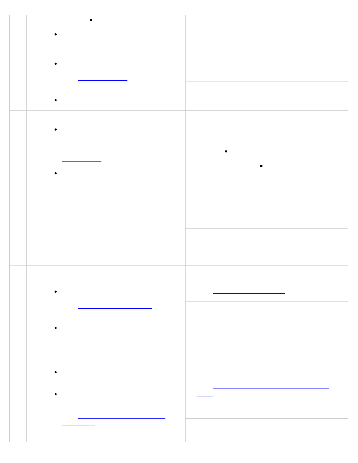
BOO
Are all PIDs normal?
CAUTION:
INSPECT BRAKE SWITCH
8
Inspect the brake switch.
BRAKE SWITCH
(See
INSPECTION.)
Is there any malfunction?
INSPECT BRAKE PEDAL PLAY AMOUNT
9
Inspect the brake pedal play
amount.
YesReplace the brake switch, then go to Step 11.
BRAKE PEDAL REMOVAL/INSTALLATION.)
(See
No Go to the next step.
YesInspect the wiring harness related to the brake
switch for connector disconnection, short circuit,
and poor contact.
(See BRAKE PEDAL
INSPECTION.)
Is the amount of brake pedal
play normal?
VERIFY IF A DTC RELATED TO DRIVE-BY-
10
WIRE CONTROL IS DETECTED
Perform the KOER self test.
KOEO/KOER SELF TEST
(See
[13B-MSP].)
If there is any malfunction:
Repair or
replace the
malfunctioning
part according
to the
inspection
results, then
go to Step 11.
No Repair or replace the malfunctioning part
according to the inspection results, then go to
Step 11.
YesGo to the applicable DTC inspection.
(See DTC TABLE [13B-MSP].)
No Go to the next step.
Is a DTC related to the drive-bywire control present?
VERIFY DTC TROUBLESHOOTING
11
COMPLETED
Make sure to reconnect all
disconnected connectors.
Clear the DTC from the PCM
memory using the M-MDS.
(See AFTER REPAIR PROCEDURE
[13B-MSP].)
YesRepeat the inspection from Step 1.
If the malfunction recurs, replace the PCM.
PCM REMOVAL/INSTALLATION [13B-
(See
MSP].)
Go to the next step.
No Go to the next step.
Page 92
While performing this step,
always operate the vehicle in a
safe and lawful manner.
When the M-MDS is used to
observe monitor system status
while driving, be sure to have
another technician with you, or
record the data in the M-MDS
using the PID/DATA MONITOR
AND RECORD capturing function
and inspect later.
Drive the vehicle under the
snapshot data condition.
Perform the KOER self test.
KOEO/KOER SELF TEST
(See
[13B-MSP].)
Is the same DTC present?
VERIFY AFTER REPAIR PROCEDURE
12
Perform the “AFTER REPAIR
PROCEDURE”.
YesGo to the applicable DTC inspection.
DTC TABLE [13B-MSP].)
(See
(See AFTER REPAIR PROCEDURE
[13B-MSP].)
Are any DTCs present?
< Previous Next >
No DTC troubleshooting completed.
Back to Top
© 2012 Mazda North American Operations, U.S.A.
Page 93
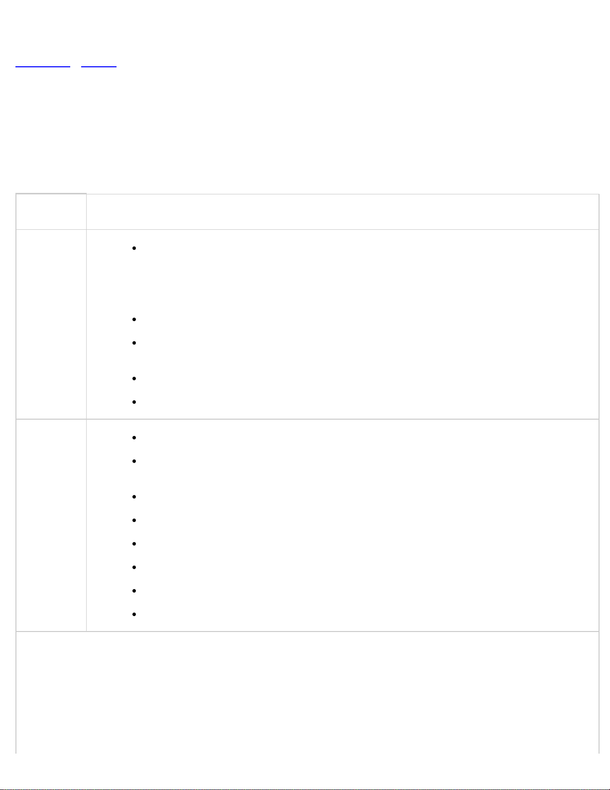
< Previous Next >
2011 - RX-8 - Engine
DTC P0332 [13B-MSP]
DTC P0332 KS No.2 circuit low input
The PCM monitors the input voltage from the KS No.2 when the engine is running.
If the input voltage is less than 1.2 V , the PCM determines that the KS No.2
circuit input voltage is low.
Diagnostic support note
DETECTION
CONDITION
POSSIBLE
CAUSE
This is a continuous monitor (CCM).
The MIL illuminates if the PCM detects the above malfunction condition in the first
drive cycle.
FREEZE FRAME DATA (Mode 2/Mode 12) is available.
The DTC is stored in the PCM memory.
KS No.2 connector or terminals malfunction
Short to ground in wiring harness between KS No.2 terminal A and PCM terminal
2AC
Short to ground in wiring harness between KS No.2 terminal B and PCM terminal 2Y
KS No.2 malfunction
PCM connector or terminals malfunction
Open circuit in wiring harness between KS No.2 terminal A and PCM terminal 2AC
Open circuit in wiring harness between KS No.2 terminal B and PCM terminal 2Y
PCM malfunction
Page 94
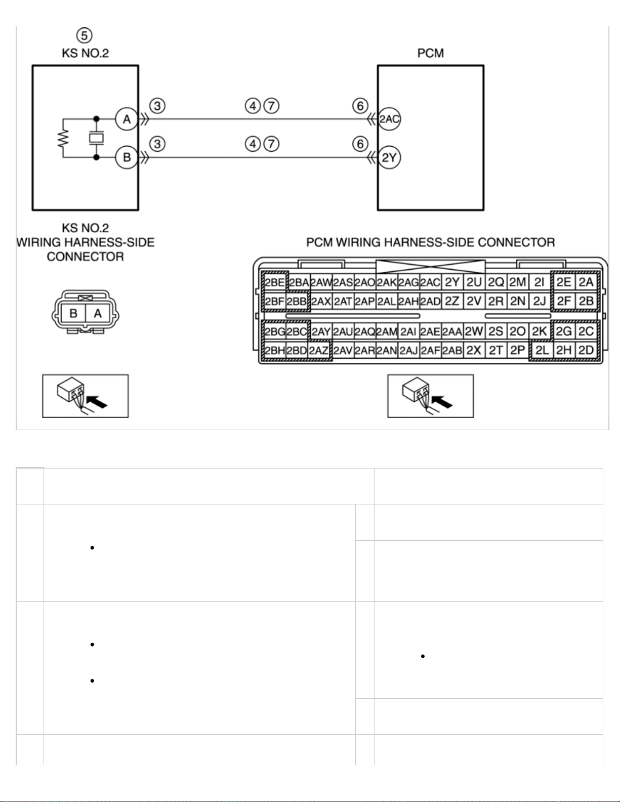
Diagnostic procedure
STEP INSPECTION ACTION
VERIFY FREEZE FRAME DATA (MODE 12) HAS BEEN
1
RECORDED
YesGo to the next step.
Has the FREEZE FRAME DATA (Mode 12)
been recorded?
No Record the FREEZE FRAME DATA (Mode
12) on the repair order, then go to the next
step.
VERIFY RELATED REPAIR INFORMATION
2
AVAILABILITY
YesPerform repair or diagnosis according to the
available repair information.
Verify related Service Bulletins and/or online repair information availability.
If the vehicle is not
repaired, go to the next
Is any related repair information available?
step.
No Go to the next step.
INSPECT KS NO.2 CONNECTOR FOR POOR
3
CONNECTION
YesRepair or replace the connector and/or
Page 95
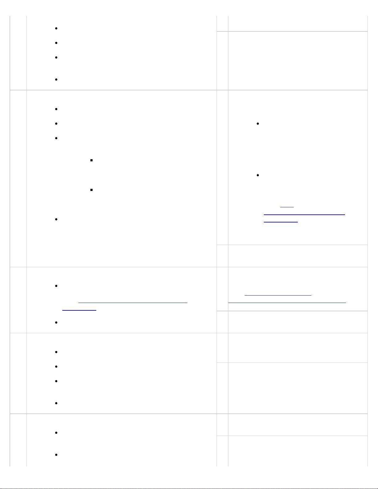
Turn the ignition switch off.
terminals, then go to Step 8.
Disconnect the KS No.2 connector.
Inspect for poor connection (such as
damaged/pulled-out pins, corrosion).
Is there any malfunction?
INSPECT KS NO.2 CIRCUIT FOR SHORT TO GROUND
4
KS No.2 connector is disconnected.
Turn the ignition switch off.
Inspect for continuity between the
following circuits:
KS No.2 terminal A (wiring
harness-side) and body
ground
KS No.2 terminal B (wiring
harness-side) and body
ground
Is there continuity?
No Go to the next step.
YesIf the short to ground circuit could be
detected:
Repair or replace the
wiring harness for a
possible short to ground.
If the short to ground circuit could not be
detected:
Replace the PCM (short to
ground in the PCM internal
circuit).
(See
PCM
REMOVAL/INSTALLATION
[13B-MSP].)
INSPECT KS NO.2
5
Inspect the KS No.2.
KNOCK SENSOR (KS) INSPECTION
(See
[13B-MSP].)
Is there any malfunction?
INSPECT PCM CONNECTOR FOR POOR CONNECTION
6
Turn the ignition switch off.
Disconnect the PCM connector.
Inspect for poor connection (such as
damaged/pulled-out pins, corrosion).
Is there any malfunction?
Go to Step 8.
No Go to the next step.
YesReplace the KS No.2, then go to Step 8.
KNOCK SENSOR (KS)
(See
REMOVAL/INSTALLATION [13B-MSP].)
No Go to the next step.
YesRepair or replace the connector and/or
terminals, then go to Step 8.
No Go to the next step.
INSPECT KS NO.2 CIRCUIT FOR OPEN CIRCUIT
7
KS No.2 and PCM connectors are
disconnected.
Turn the ignition switch off.
YesGo to the next step.
No Repair or replace the wiring harness for a
possible open circuit, then go to the next
step.
Page 96
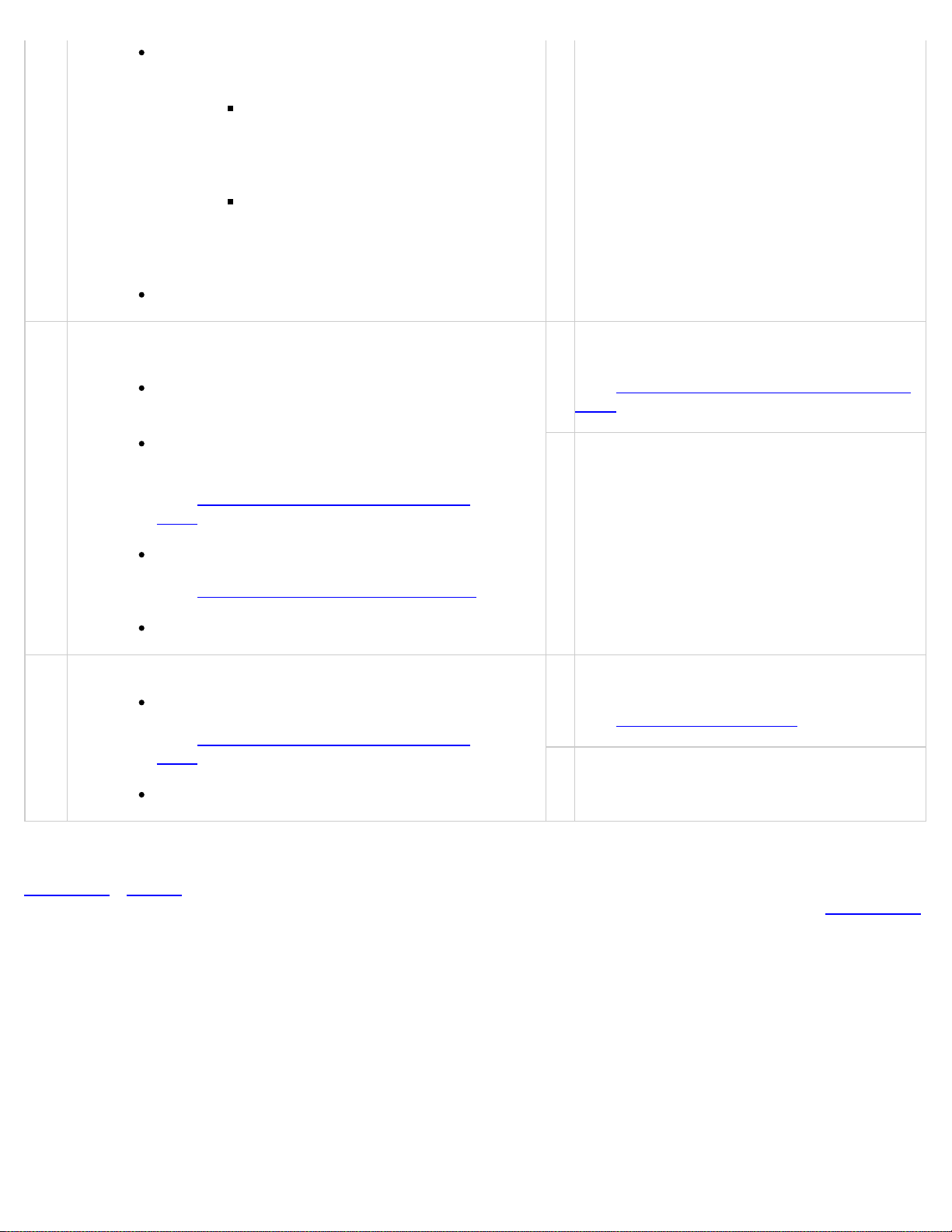
Inspect for continuity between the
following circuits:
Is there continuity?
VERIFY TROUBLESHOOTING OF DTC P0332
8
COMPLETED
Make sure to reconnect all disconnected
connectors.
Clear the DTC from the PCM memory using
the M-MDS.
AFTER REPAIR PROCEDURE [13B-
(See
MSP].)
Perform the KOEO or KOER self test.
KS No.2 terminal A (wiring
harness-side) and PCM
terminal 2AC (wiring
harness-side)
KS No.2 terminal B (wiring
harness-side) and PCM
terminal 2Y (wiring
harness-side)
YesReplace the PCM, then go to the next step.
PCM REMOVAL/INSTALLATION [13B-
(See
MSP].)
No Go to the next step.
KOEO/KOER SELF TEST [13B-MSP].)
(See
Is the same DTC present?
VERIFY AFTER REPAIR PROCEDURE
9
Perform the “AFTER REPAIR PROCEDURE”.
AFTER REPAIR PROCEDURE [13B-
(See
MSP].)
Are any DTCs present?
< Previous Next >
© 2011 Mazda North American Operations, U.S.A.
YesGo to the applicable DTC inspection.
DTC TABLE [13B-MSP].)
(See
No DTC troubleshooting completed.
Back to Top
Page 97
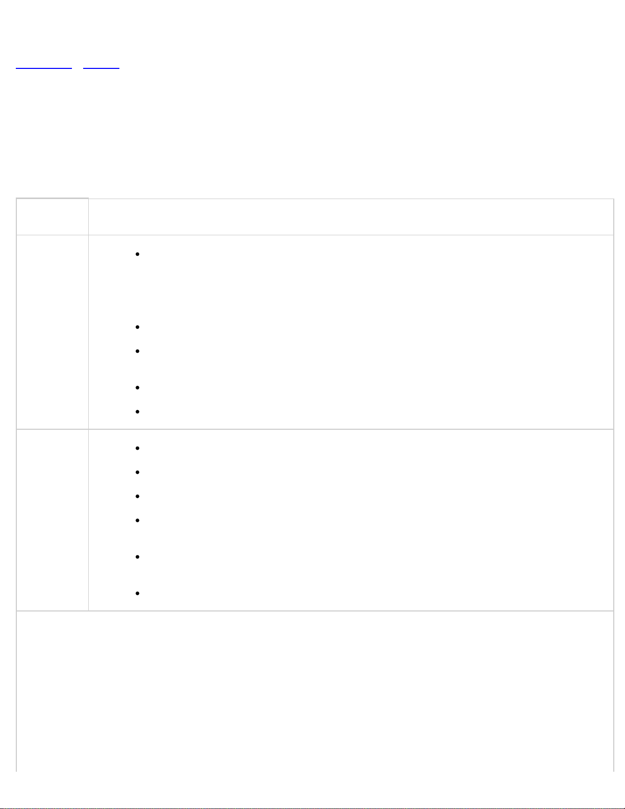
< Previous Next >
2011 - RX-8 - Engine
DTC P0333 [13B-MSP]
DTC P0333 KS No.2 circuit high input
The PCM monitors the input voltage from the KS No.2 when the engine is running.
If the input voltage is more than 4.0 V, the PCM determines that the KS No.2
circuit input voltage is high.
Diagnostic support note
DETECTION
CONDITION
POSSIBLE
CAUSE
This is a continuous monitor (CCM).
The MIL illuminates if the PCM detects the above malfunction condition in the first
drive cycle.
FREEZE FRAME DATA (Mode 2/Mode 12) is available.
The DTC is stored in the PCM memory.
KS No.2 connector or terminals malfunction
KS No.2 malfunction
PCM connector or terminals malfunction
Short to power supply in wiring harness between KS No.2 terminal A and PCM
terminal 2AC
Short to power supply in wiring harness between KS No.2 terminal B and PCM
terminal 2Y
PCM malfunction
Page 98
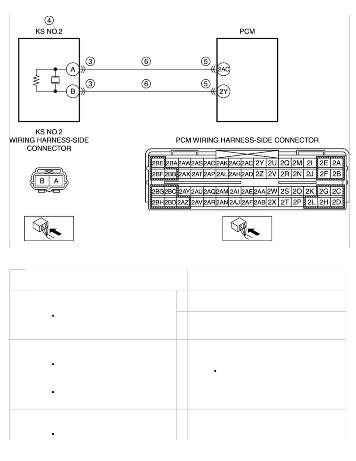
Diagnostic procedure
STEP INSPECTION ACTION
VERIFY FREEZE FRAME DATA (MODE 12)
1
HAS BEEN RECORDED
YesGo to the next step.
Has the FREEZE FRAME DATA
(Mode 12) been recorded?
No Record the FREEZE FRAME DATA (Mode 12) on the
repair order, then go to the next step.
VERIFY RELATED REPAIR INFORMATION
2
AVAILABILITY
YesPerform repair or diagnosis according to the available
repair information.
Verify related Service Bulletins
and/or on-line repair information
availability.
If the vehicle is not repaired, go to
the next step.
Is any related repair information
available?
No Go to the next step.
INSPECT KS NO.2 CONNECTOR FOR POOR
3
CONNECTION
YesRepair or replace the connector and/or terminals,
then go to Step 7.
Turn the ignition switch off.
Page 99
Disconnect the KS No.2
connector.
Inspect for poor connection (such
as damaged/pulled-out pins,
corrosion).
Is there any malfunction?
INSPECT KS NO.2
4
Inspect the KS No.2.
(See
INSPECTION [13B-MSP].)
KNOCK SENSOR (KS)
No Go to the next step.
YesReplace the KS No.2, then go to Step 7.
KNOCK SENSOR (KS) REMOVAL/INSTALLATION
(See
[13B-MSP].)
Is there any malfunction?
INSPECT PCM CONNECTOR FOR POOR
5
CONNECTION
Turn the ignition switch off.
Disconnect the PCM connector.
Inspect for poor connection (such
as damaged/pulled-out pins,
corrosion).
Is there any malfunction?
INSPECT KS NO.2 CIRCUIT FOR SHORT TO
6
POWER SUPPLY
KS No.2 and PCM connectors are
disconnected.
Turn the ignition switch to the ON
position (engine off).
Measure the voltage between the
following circuits:
No Go to the next step.
YesRepair or replace the connector and/or terminals,
then go to Step 7.
No Go to the next step.
YesRepair or replace the wiring harness for a possible
short to power supply, then go to the next step.
No Go to the next step.
KS No.2 terminal
A (wiring
harness-side)
and body ground
KS No.2 terminal
B (wiring
harness-side)
and body ground
Is the voltage B+?
VERIFY TROUBLESHOOTING OF DTC P0333
7
COMPLETED
Make sure to reconnect all
disconnected connectors.
YesReplace the PCM, then go to the next step.
(See
PCM REMOVAL/INSTALLATION [13B-MSP].)
Page 100
Clear the DTC from the PCM
memory using the M-MDS.
AFTER REPAIR PROCEDURE
(See
[13B-MSP].)
Perform the KOEO or KOER self
test.
KOEO/KOER SELF TEST
(See
[13B-MSP].)
Is the same DTC present?
VERIFY AFTER REPAIR PROCEDURE
8
Perform the “AFTER REPAIR
PROCEDURE”.
AFTER REPAIR PROCEDURE
(See
[13B-MSP].)
Are any DTCs present?
No Go to the next step.
YesGo to the applicable DTC inspection.
DTC TABLE [13B-MSP].)
(See
No DTC troubleshooting completed.
< Previous Next >
Back to Top
© 2011 Mazda North American Operations, U.S.A.
 Loading...