

Page 1
Engine
CONTENTS
Workshop
Manual
LF
L3
FOREWORD
This manual explains the service points for
the above-indicated automotive system.
This manual covers all models with the
above-indicated automotive system, not any
one specific model.
In order to do these procedures safely,
quickly, and correctly, you must first read
this manual and any other relevant service
materials carefully.
Title Section
GENERAL INFORMATION 00
ENGINE
© 2005 Mazda Motor Corporation
PRINTED IN U.S.A., AUGUST 2005
Form No. 1866–1U–05H
Part No. 9999–95–LFL3–05
01
All the contents of this manual, including
drawings and specifications, are the latest
available at the time of printing.
As modifications affecting repair or
maintenance occur, relevant information
supplementary to this volume will be made
available at Mazda dealers. This manual
should be kept up-to-date.
Mazda Motor Corporation reserves the right
to alter the specifications and contents of
this manual without obligation or advance
notice.
All rights reserved. No part of this book may
be reproduced or used in any form or by any
means, electronic or mechanical—including
photocopying and recording and the use of
any kind of information storage and retrieval
system—without permission in writing.
Mazda Motor Corporation
HIROSHIMA, JAPAN
Page 2

Page 3
GENERAL INFORMATION
To c of SCT
GENERAL INFORMATION . . . . 00-00
To c of SCT
00–00 GENERAL INFORMATION
00
SECTION
00–00
HOW TO USE THIS MANUAL . . . . . . . . . 00–00–2
Range of Topics . . . . . . . . . . . . . . . . . . 00–00–2
Service Procedure . . . . . . . . . . . . . . . . 00–00–2
Symbols . . . . . . . . . . . . . . . . . . . . . . . . 00–00–4
Advisory Messages . . . . . . . . . . . . . . . . 00–00–4
UNITS . . . . . . . . . . . . . . . . . . . . . . . . . . . .00–00–5
Conversion to SI Units (Système
International d'Unités) . . . . . . . . . . . . . 00–00–5
Rounding Off. . . . . . . . . . . . . . . . . . . . . 00–00–5
Upper and Lower Limits . . . . . . . . . . . . 00–00–5
FUNDAMENTAL PROCEDURES. . . . . . . 00–00–6
Preparation of Tools and Measuring
Equipment. . . . . . . . . . . . . . . . . . . . . . 00–00–6
Special Service Tools . . . . . . . . . . . . . . 00–00–6
Disassembly . . . . . . . . . . . . . . . . . . . . . 00–00–6
End of Toc
Inspection During Removal,
Disassembly. . . . . . . . . . . . . . . . . . . . 00–00–6
Arrangement of Parts . . . . . . . . . . . . . . 00–00–7
Cleaning of Parts . . . . . . . . . . . . . . . . . 00–00–7
Reassembly . . . . . . . . . . . . . . . . . . . . . 00–00–7
Adjustment . . . . . . . . . . . . . . . . . . . . . . 00–00–7
Rubber Parts and Tubing . . . . . . . . . . . 00–00–8
Hose Clamps . . . . . . . . . . . . . . . . . . . . 00–00–8
Torque Formulas . . . . . . . . . . . . . . . . . 00–00–8
Vise . . . . . . . . . . . . . . . . . . . . . . . . . . . 00–00–8
ELECTRICAL SYSTEM. . . . . . . . . . . . . . 00–00–9
Connectors. . . . . . . . . . . . . . . . . . . . . . 00–00–9
NEW STANDARDS . . . . . . . . . . . . . . . . . 00–00–11
ABBREVIATIONS . . . . . . . . . . . . . . . . . . 00–00–12
00–00–1
Page 4
GENERAL INFORMATION
HOW TO USE THIS MANUAL
E5U000000000E01
Range of Topics
• This manual contains procedures for performing all required service operations. The procedures are divided
into the following five basic operations:
— Removal/Installation
— Disassembly/Assembly
— Replacement
— Inspection
— Adjustment
• Simple operations which can be performed easily just by looking at the vehicle (i.e., removal/installation of
parts, jacking, vehicle lifting, cleaning of parts, and visual inspection) have been omitted.
Service Procedure
Inspection, adjustment
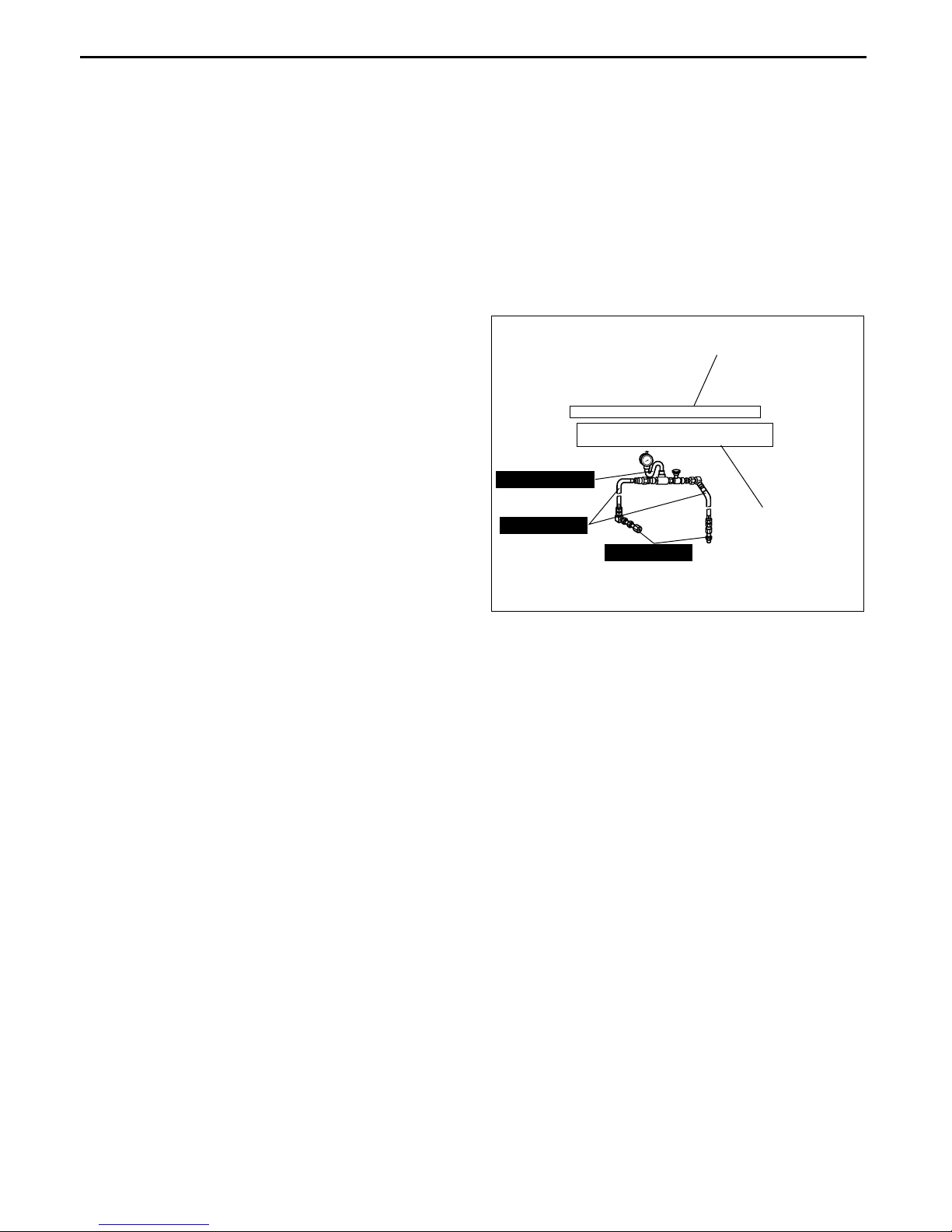
• Inspection and adjustment procedures are
divided into steps. Important points regarding the
location and contents of the procedures are
SHOWS PROCEDURE ORDER
FOR SERVICE
explained in detail and shown in the illustrations.
Fluid Pressure Inspection
1. Assemble the SSTs as shown in the figure.
Tightening torque
39—49 N·m {4.0—5.0 kgf·m, 29—36 ft·lbf}
49 1232 670A
49 H002 671
49 H032 322
Caution
Connect the gauge set from under
the vehicle to prevent contact with
the drive belt and the cooling fan.
SHOWS TIGHTENING
TORQUE
SPECIFICATIONS
WGIWXX0009E
00–00–2
Page 5

GENERAL INFORMATION
GREASE
GREASE
Repair procedure
1. Most repair operations begin with an overview illustration. It identifies the components, shows how the parts fit
together, and describes visual part inspection. However, only removal/installation procedures that need to be
performed methodically have written instructions.
2. Expendable parts, tightening torques, and symbols for oil, grease, and sealant are shown in the overview
illustration. In addition, symbols indicating parts requiring the use of special service tools or equivalent are also
shown.
3. Procedure steps are numbered and the part that is the main point of that procedure is shown in the illustration
with the corresponding number. Occasionally, there are important points or additional information concerning a
procedure. Refer to this information when servicing the related part.
00–00
Procedure
"Removal/Installation"
Portion
"Inspection After
Installation" Portion
INSTALL THE PARTS BY
PERFORMING STEPS
—
1—3 IN REVERSE ORDER
SHOWS THERE
ARE REFERRAL
NOTES FOR SERVICE
LOWER TRAILING LINK, UPPER TRAILING LINK REMOVAL/INSTALLATION
1
1. Jack up the rear of the vehicle and suppor t it with safety stands.
2. Remove the undercover. (See 01-10-4 Undercover Removal)
3. Remove in the order indicated in the table.
4. Install in the reverse order of removal.
5. Inspect the rear wheel alignment and adjust it if necessary.
2
11
SHOWS PROCEDURE ORDER
FOR SERVICE
10
44—60 {4.4—6.2, 32—44}
SHOWS TIGHTENING
TORQUE
SPECIFICATIONS
SST
3
5
6
SST
4
94—116 {9.5—11.9, 69—86}
Split pin
1
Nut
2
Lower trailing link ball joint
3
(See 02-14-5 Lower Trailing Link Ball Joint Removal Note)
Bolt
4
Lower trailing link
5
Dust boot (lower trailing link)
6
GREASE
R
7
8 Nut
9 Upper trailing link ball joint
10
11
12
SHOWS SERVICE
ITEM (S)
INDICATES ANY RELEVANT
REFERENCES WHICH NEED
TO BE FOLLOWED DURING
INSTALLATION
SHOWS SPECIAL
SST
9
SST
12
43—56 {4.3—5.8, 32—41}
8
R
7
R
SERVICE TOOL (SST)
FOR SERVICE OPERATION
GREASE
SHOWS APPLICATION
POINTS OF GREASE, ETC.
SHOWS NON-REUSEABLE PARTS
SHOWS DETAILS
118—156 {12.0—16.0, 87—115}
2
R
1
N·m {kgf·m, ft·lbf}
Split pin
(See 02-14-5 Upper Trailing Link Ball Joint Removal Note)
Nut
Upper trailing link
Dust boot (upper trailing link)
SHOWS TIGHTENING
TORQUE UNITS
Lower Trailing Link Ball Joint, Upper Trailing Link
Ball Joint Removal Note
Remove the ball joint using the SSTs.
SHOWS REFERRAL
NOTES FOR
SERVICE
SHOWS SPECIAL
SERVICE TOOL (SST)
NO.
KNUCKLE
49 T028 304
49 T028 305
UPPER TRAILING LINK
LOWER TRAILING LINK
49 T028 303
BHE0000W104
00–00–3
Page 6
GENERAL INFORMATION
TF
GREASE
Symbols
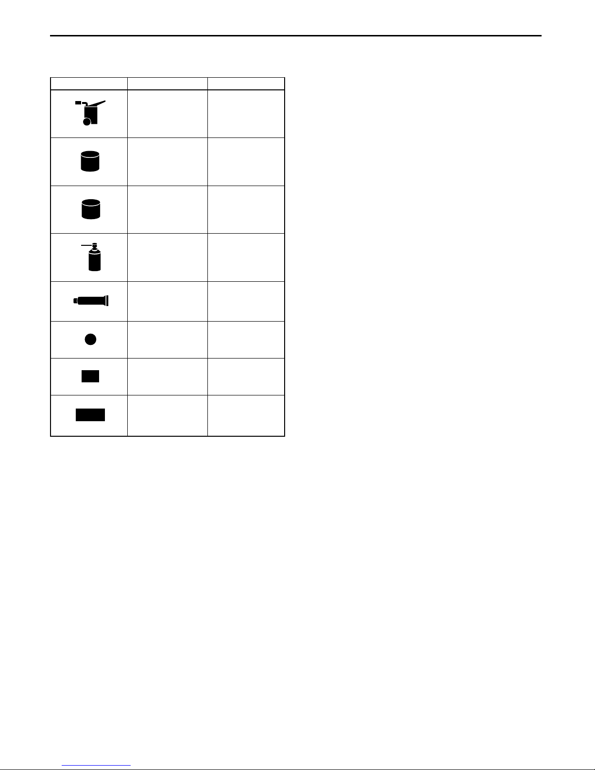
• There are eight symbols indicating oil, grease, fluids, sealant, and the use of SST or equivalent. These symbols
show application points or use of these materials during service.
Symbol Meaning Kind
OIL
BRAKE
FLUID
AATF
GREASE
SEALANT
P
R
Apply oil
Apply brake fluid
Apply automatic
transaxle/
transmission fluid
Apply grease
Apply sealant
Apply petroleum
jelly
Replace part
New appropriate
engine oil or gear
oil
New appropriate
brake fluid
New appropriate
automatic
transaxle/
transmission fluid
Appropriate
grease
Appropriate
sealant
Appropriate
petroleum jelly
O-ring, gasket,
etc.
SST
Use SST or
equivalent
Appropriate tools
Advisory Messages
• You will find several Warnings, Cautions, Notes, Specifications and Upper and Lower Limits in this
manual.
Warning
• A Warning indicates a situation in which serious injury or death could result if the warning is ignored.
Caution
• A Caution indicates a situation in which damage to the vehicle or parts could result if the caution is ignored.
Note
• A Note provides added information that will help you to complete a particular procedure.
Specification
• The values indicate the allowable range when performing inspections or adjustments.
Upper and lower limits
• The values indicate the upper and lower limits that must not be exceeded when performing inspections or
adjustments.
End Of Sie
00–00–4
Page 7

GENERAL INFORMATION
UNITS
Electric current A (ampere)
Electric power W (watt)
Electric resistance ohm
Electric voltage V (volt)
Length
Negative pressure
Positive pressure
Number of
revolutions
To r qu e
Volume
Weight
mm (millimeter)
in (inch)
kPa (kilo pascal)
mmHg (millimeters of mercury)
inHg (inches of mercury)
kPa (kilo pascal)
2
kgf/cm
centimeter)
psi (pounds per square inch)
rpm (revolutions per minute)
N·m (Newton meter)
kgf·m (kilogram force meter)
kgf·cm (kilogram force centimeter)
ft·lbf (foot pound force)
in·lbf (inch pound force)
L (liter)
US qt (U.S. quart)
Imp qt (Imperial quart)
ml (milliliter)
cc (cubic centimeter)
cu in (cubic inch)
fl oz (fluid ounce)
g (gram)
oz (ounce)
(kilogram force per square
E5U000000000E02
00–00
Conversion to SI Units (Système International d'Unités)
• All numerical values in this manual are based on SI units. Numbers shown in conventional units are converted
from these values.
Rounding Off
• Converted values are rounded off to the same number of places as the SI unit value. For example, if the SI unit
value is 17.2 and the value after conversion is 37.84, the converted value will be rounded off to 37.8.
Upper and Lower Limits
• When the data indicates upper and lower limits, the converted values are rounded down if the SI unit value is
an upper limit and rounded up if the SI unit value is a lower limit. Therefore, converted values for the same SI
unit value may differ after conversion. For example, consider 2.7 kgf/cm
210—260 kPa {2.1—2.7 kgf/cm
270—310 kPa {2.7—3.2 kgf/cm
• The actual converted values for 2.7 kgf/cm
2
, 30—38 psi}
2
, 39—45 psi}
2
are 264 kPa and 38.4 psi. In the first specification, 2.7 is used as
2
in the following specifications:
an upper limit, so the converted values are rounded down to 260 and 38. In the second specification, 2.7 is
used as a lower limit, so the converted values are rounded up to 270 and 39.
End Of Sie
00–00–5
Page 8
GENERAL INFORMATION
FUNDAMENTAL PROCEDURES
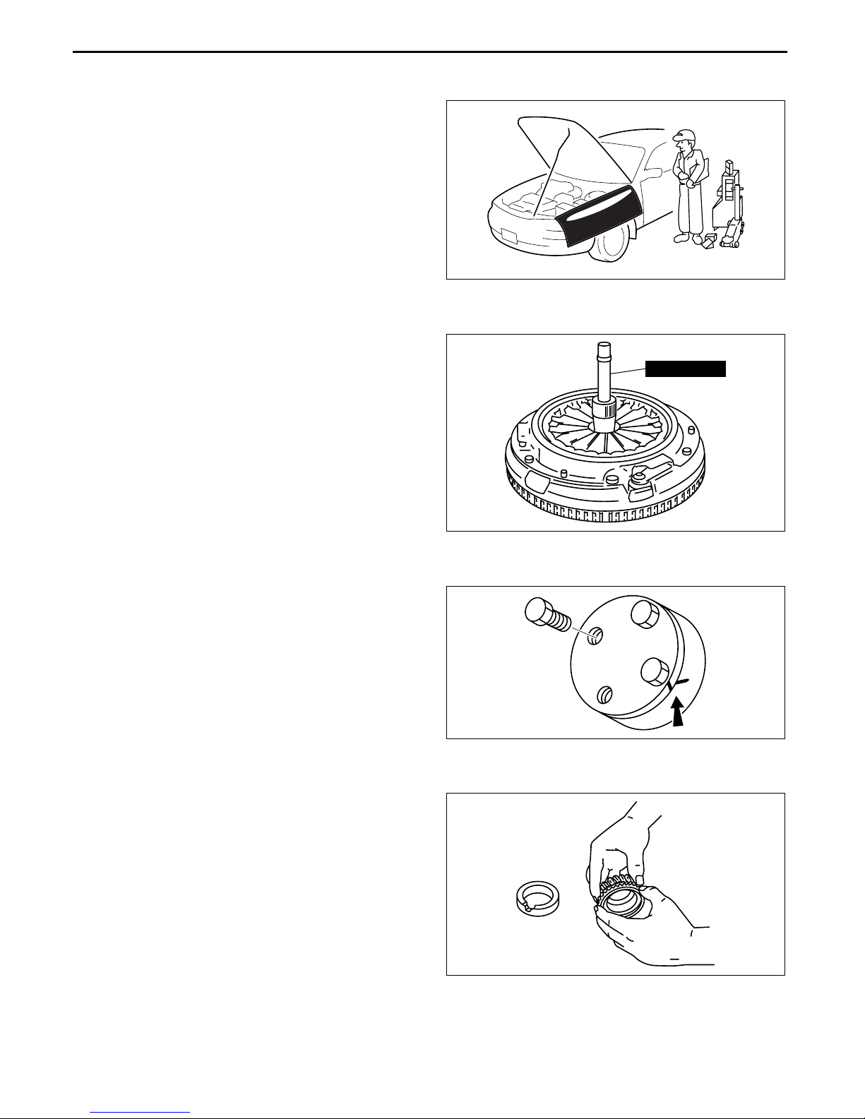
Preparation of Tools and Measuring Equipment
• Be sure that all necessary tools and measuring
equipment are available before starting any work.
Special Service Tools
• Use special service tools or equivalent when they
are required.
E5U000000000E03
CHU0014W003
49 SE01 310
Disassembly
• If the disassembly procedure is complex,
requiring many parts to be disassembled, all parts
should be marked in a place that will not affect
their performance or external appearance and
identified so that reassembly can be performed
easily and efficiently.
Inspection During Removal, Disassembly
• When removed, each part should be carefully
inspected for malfunction, deformation, damage
and other problems.
WGIWXX0024E
WGIWXX0027E
00–00–6
WGIWXX0028E
Page 9
GENERAL INFORMATION
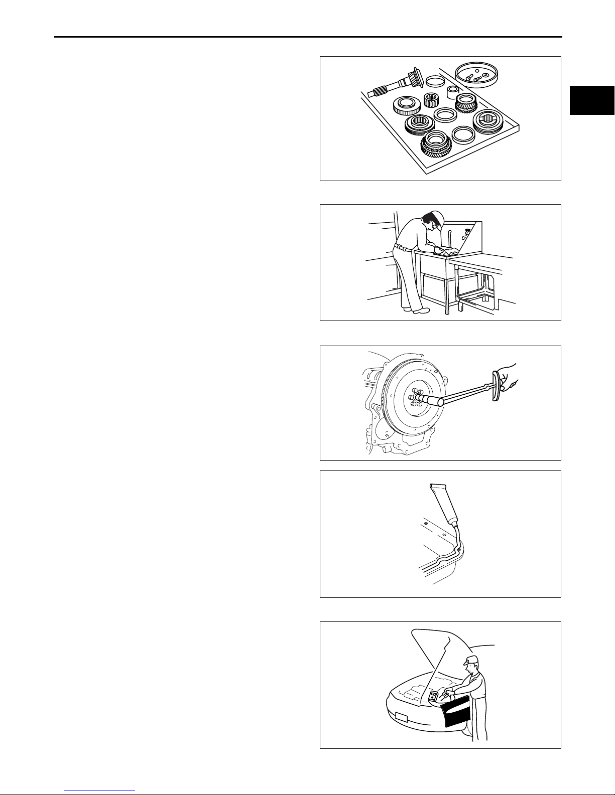
Arrangement of Parts
• All disassembled parts should be carefully
arranged for reassembly.
• Be sure to separate or otherwise identify the parts
to be replaced from those that will be reused.
Cleaning of Parts
• All parts to be reused should be carefully and
thoroughly cleaned in the appropriate method.
Warning
• Using compressed air can cause dirt and
other particles to fly out causing injury to
the eyes. Wear protective eye wear
whenever using compressed air.
00–00
WGIWXX0029E
Reassembly
• Standard values, such as torques and certain
adjustments, must be strictly observed in the
reassembly of all parts.
• If removed, the following parts should be replaced
with new ones:
— Oil seals
— Gaskets
— O-rings
— Lockwashers
— Cotter pins
— Nylon nuts
• Depending on location:
— Sealant and gaskets, or both, should be
applied to specified locations. When sealant
is applied, parts should be installed before
sealant hardens to prevent leakage.
— Oil should be applied to the moving
components of parts.
— Specified oil or grease should be applied at
the prescribed locations (such as oil seals)
before reassembly.
Adjustment
• Use suitable gauges and testers when making
adjustments.
C5U0000W001
WGIWXX0031E
CHU0014W006
CHU0014W005
00–00–7
Page 10
GENERAL INFORMATION
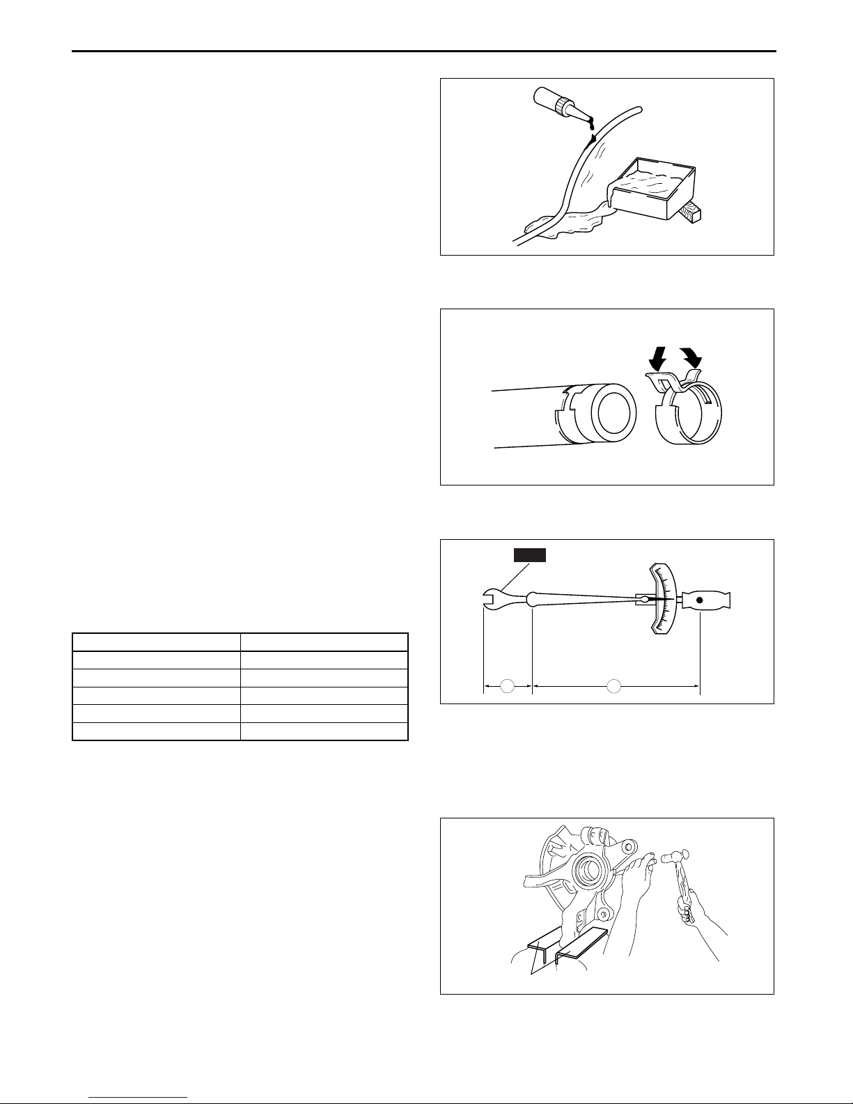
Rubber Parts and Tubing
• Prevent gasoline or oil from getting on rubber
parts or tubing.
Hose Clamps
• When reinstalling, position the hose clamp in the
original location on the hose and squeeze the
clamp lightly with large pliers to ensure a good fit.
WGIWXX0034E
Torque Formulas
• When using a torque wrench-SST or equivalent
combination, the written torque must be
recalculated due to the extra length that the SST
or equivalent adds to the torque wrench.
Recalculate the torque by using the following
formulas. Choose the formula that applies to you.
Torque Unit Formula
N·m N·m × [L/(L+A)]
kgf·m kgf·m × [L/(L+A)]
kgf·cm kgf·cm × [L/(L+A)]
ft·lbf ft·lbf × [L/(L+A)]
in·lbf in·lbf × [L/(L+A)]
A : The length of the SST past the torque wrench drive.
L : The length of the torque wrench.
Vise
• When using a vise, put protective plates in the
jaws of the vise to prevent damage to parts.
End Of Sie
WGIWXX0035E
SST
A
L
3
2
1
0
1
2
3
WGIWXX0036E
00–00–8
PROTECTIVE PLATES
CHU0014W010
Page 11
GENERAL INFORMATION
ELECTRICAL SYSTEM
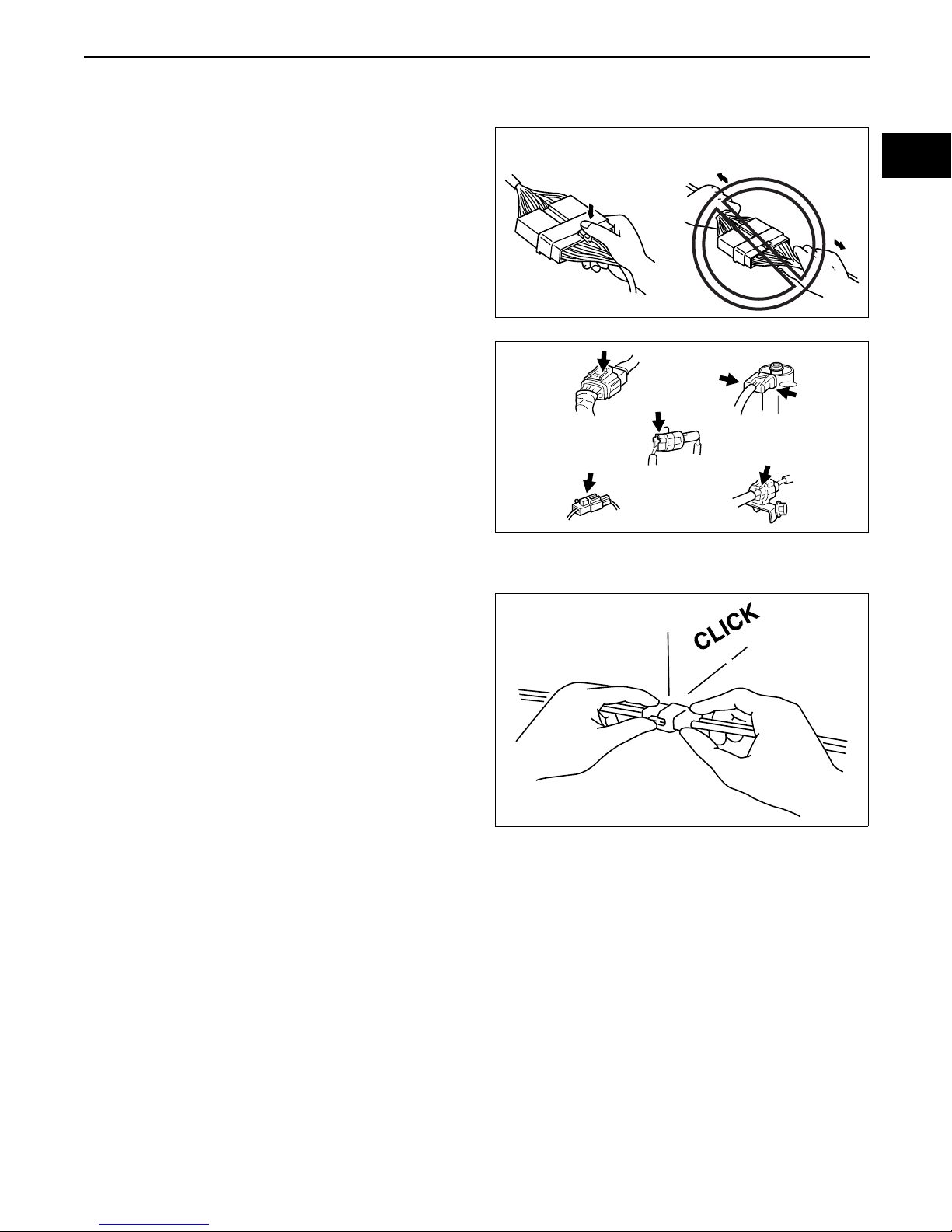
Connectors
Disconnecting connectors
• When disconnecting connector, grasp the
connectors, not the wires.
• Connectors can be disconnected by pressing or
pulling the lock lever as shown.
GOOD
NO GOOD
E5U000000000E04
00–00
CHU0000W014
Locking connector
• When locking connectors, listen for a click
indicating they are securely locked.
WGIWXX0042E
WGIWXX0043E
00–00–9
Page 12
GENERAL INFORMATION
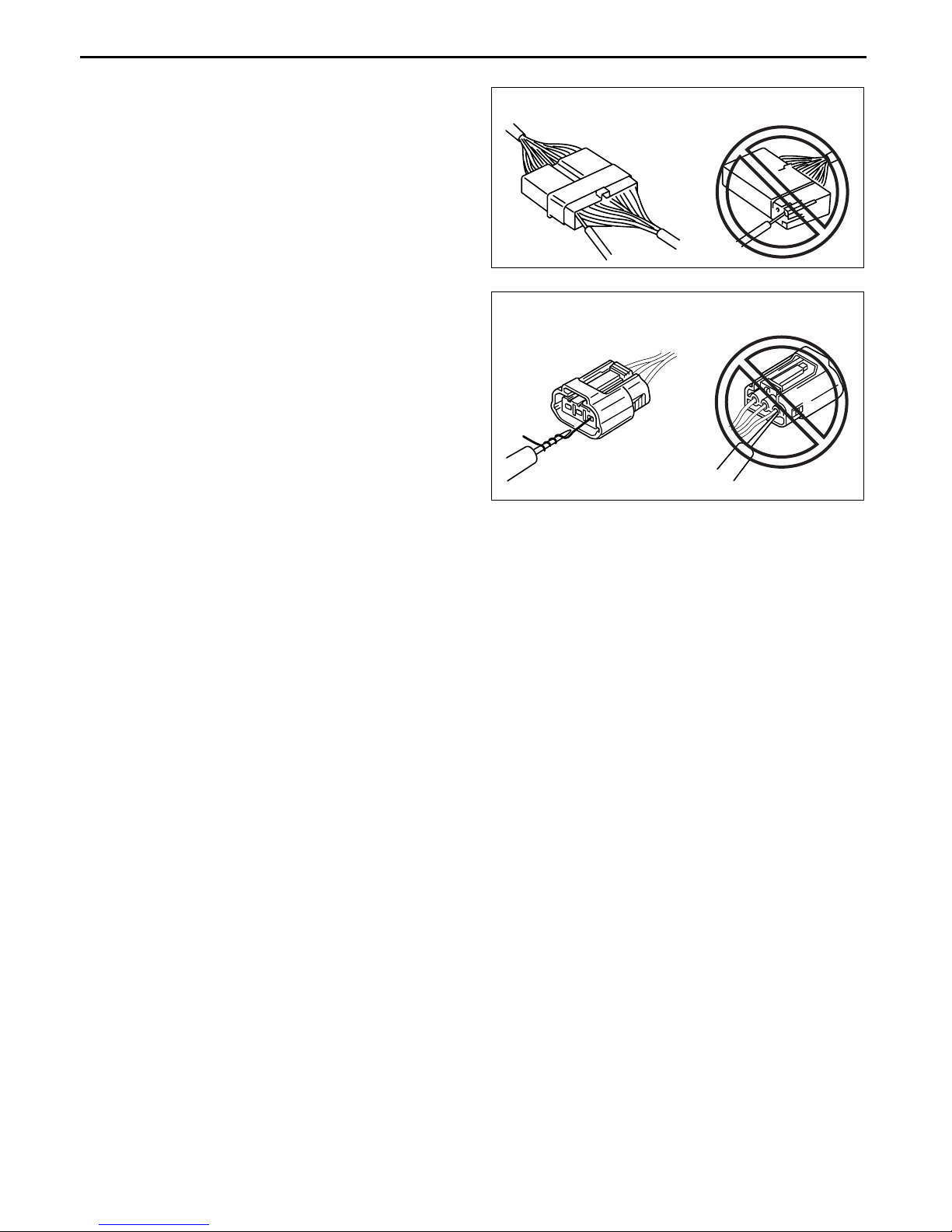
Inspection
• When a tester is used to inspect for continuity or
measuring voltage, insert the tester probe from
the wiring harness side.
• Inspect the terminals of waterproof connectors
from the connector side since they cannot be
accessed from the wiring harness side.
Caution
• To prevent damage to the terminal, wrap
a thin wire around the tester probe before
inserting into terminal.
End Of Sie
GOOD
NO GOOD
GOOD NO GOOD
CHU0000W011
CHU0000W012
00–00–10
Page 13
GENERAL INFORMATION
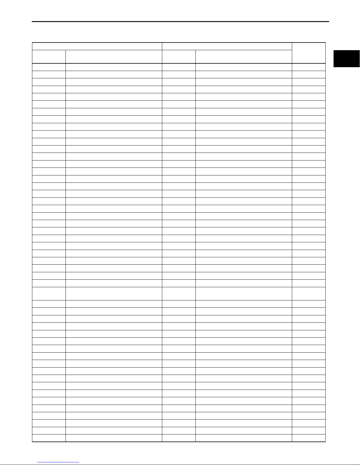
NEW STANDARDS
• Following is a comparison of the previous standard and the new standard.
New Standard Previous Standard
Abbrevi-
ation
AP Accelerator Pedal — Accelerator Pedal
ACL Air Cleaner — Air Cleaner
A/C Air Conditioning — Air Conditioning
BARO Barometric Pressure — Atmospheric Pressure
B+ Battery Positive Voltage Vb Battery Voltage
— Brake Switch — Stoplight Switch
— Calibration Resistor — Corrected Resistance #6
CMP sensor Camshaft Position Sensor — Crank Angle Sensor
CAC Charge Air Cooler — Intercooler
CLS Closed Loop System — Feedback System
CTP Closed Throttle Position — Fully Closed
CPP Clutch Pedal Position — Idle Switch
CIS Continuous Fuel Injection System — Clutch Position
CS sensor Control Sleeve Sensor CSP sensor Control Sleeve Position Sensor #6
CKP sensor Crankshaft Position Sensor — Crank Angle Sensor 2
DLC Data Link Connector — Diagnosis Connector
DTM Diagnostic Test Mode — Test Mode #1
DTC Diagnostic Trouble Code(s) — Service Code(s)
DI Distributor Ignition — Spark Ignition
DLI Distributorless Ignition — Direct Ignition
EI Electronic Ignition — Electronic Spark Ignition #2
ECT Engine Coolant Temperature — Water Thermo
EM Engine Modification — Engine Modification
— Engine Speed Input Signal — Engine RPM Signal
EVAP Evaporative Emission — Evaporative Emission
EGR Exhaust Gas Recirculation — Exhaust Gas Recirculation
FC Fan Control — Fan Control
FF Flexible Fuel — Flexible Fuel
4GR Fourth Gear — Overdrive
— Fuel Pump Relay — Circuit Opening Relay #3
FSO
solenoid
GEN Generator — Alternator
GND Ground — Ground/Earth
HO2S Heated Oxygen Sensor — Oxygen Sensor With heater
IAC Idle Air control — Idle Speed Control
— IDM Relay — Spill Valve Relay #6
— Incorrect Gear Ratio — —
— Injection Pump FIP Fuel Injection Pump #6
— Input/Turbine Speed Sensor — Pulse Generator
IAT Intake Air Temperature — Intake Air Thermo
KS Knock Sensor — Knock Sensor
MIL Malfunction Indicator Lamp — Malfunction Indicator Light
MAP Manifold Absolute Pressure — Intake Air Pressure
MAF sensor Mass Air Flow Sensor — Airflow Sensor
MFL Multiport Fuel Injection — Multiport Fuel Injection
OBD On-Board Diagnostic — Diagnosis/Self-Diagnosis
OL Open Loop — Open Loop
— Output Speed Sensor — Vehicle Speed Sensor 1
OC Oxidation Catalytic Converter — Catalytic Converter
O2S Oxygen Sensor — Oxygen Sensor
Fuel Shut Off Solenoid FCV Fuel Cut Valve #6
Name
Abbreviation
Name
E5U000000000E05
Remark
00–00
00–00–11
Page 14
GENERAL INFORMATION
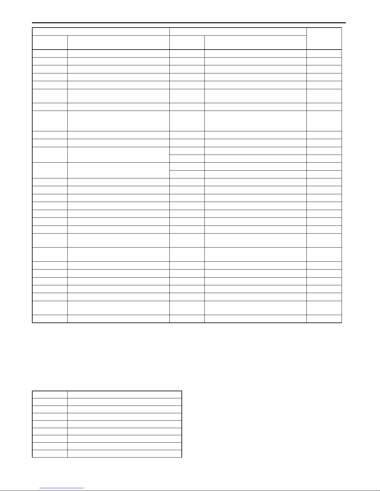
New Standard Previous Standard
Abbrevi-
ation
PNP Park/Neutral Position — Park/Neutral Range
— PCM Control Relay — Main Relay #6
PSP Power Steering Pressure — Power Steering Pressure
PCM Powertrain Control Module ECU Engine Control Unit #4
— Pressure Control Solenoid — Line Pressure Solenoid Valve
PAIR Pulsed Secondary Air Injection — Secondary Air Injection System
— Pump Speed Sensor — NE Sensor #6
AIR Secondary Air Injection — Secondary Air Injection System
SAPV Secondary Air Pulse Valve — Reed Valve
SFI Sequential Multipoint Fuel Injection — Sequential Fuel Injection
— Shift Solenoid A
— Shift Solenoid B
— Shift Solenoid C — 34 Shift Solenoid Valve
3GR Third Gear — 3rd Gear
TWC Three Way Catalytic Converter — Catalytic Converter
TB Throttle Body — Throttle Body
TP sensor Throttle Position Sensor — Throttle Sensor
TCV Timer Control Valve TCV Timing Control Valve #6
TCC Torque Converter Clutch — Lockup Position
TCM
—
TR Transmission (Transaxle) Range — Inhibitor Position
TC Turbocharger — Turbocharger
VSS Vehicle Speed Sensor — Vehicle Speed Sensor
VR Voltage Regulator — IC Regulator
VAF sensor Volume Air Flow Sensor — Air flow Sensor
WUTWC
WOT Wide Open Throttle — Fully Open
Transmission (Transaxle) Control
Module
Transmission (Transaxle) Fluid
Temperature Sensor
Warm Up Thre e Way Catalytic
Converter
Name
Abbreviation
— 12 Shift Solenoid Valve
— Shift A Solenoid Valve
— 23 Shift Solenoid Valve
— Shift B Solenoid Valve
— EC-AT Control Unit
— ATF Thermosensor
— Catalytic Converter #5
Name
Remark
Pulsed
injection
Injection
with air
pump
#1 : Diagnostic trouble codes depend on the diagnostic test mode
#2 : Controlled by the PCM
#3 : In some models, there is a fuel pump relay that controls pump speed. That relay is now called the fuel pump
relay (speed).
#4 : Device that controls engine and powertrain
#5 : Directly connected to exhaust manifold
#6 : Part name of diesel engine
End Of Sie
ABBREVIATIONS
ATDC After Top Dead Center
ATX Automatic Transaxle
EGR Exhaust Gas Recirculation
EX Exhaust
IN Intake
MTX Manual Transaxle
OCV Oil Control Valve
TDC Top Dead Center
SST Special Service Tool
End Of Sie
00–00–12
E5U000000000E06
Page 15
ENGINE
To c of SCT
MECHANICAL. . . . . . . . . . . . . .01-10
TECHNICAL DATA . . . . . . . . . . 01-50
To c of SCT
01–10 MECHANICAL
01
SECTION
01–10
SERVICE TOOLS . . . . . . . . . . . 01-60
ENGINE OVERHAUL SERVICE
WARNING. . . . . . . . . . . . . . . . . . . . . . . . 01–10–2
ENGINE
MOUNTING/DISMOUNTING . . . . . . . . . 01–10–3
DISMOUNTING. . . . . . . . . . . . . . . . . . .01–10–3
TIMING CHAIN DISASSEMBLY. . . . . . . . 01–10–4
Crankshaft Pulley Lock Bolt
Disassembly Note . . . . . . . . . . . . . . . . 01–10–5
Front Oil Seal Disassembly Note . . . . . 01–10–5
Chain Tensioner
Disassembly Note . . . . . . . . . . . . . . . . 01–10–5
Oil Pump Sprocket
Disassembly Note . . . . . . . . . . . . . . . . 01–10–5
CYLINDER HEAD (I)
DISASSEMBLY. . . . . . . . . . . . . . . . . . . . 01–10–6
Camshaft Sprocket Lock Bolt,
Variable Valve Timing Actuator
Lock Bolt Disassembly Note . . . . . . . . 01–10–7
Camshaft Cap Disassembly Note . . . . . 01–10–7
Tappet Disassembly Note . . . . . . . . . . . 01–10–7
Cylinder Head Bolt
Disassembly Note . . . . . . . . . . . . . . . . 01–10–8
CYLINDER HEAD (II)
DISASSEMBLY. . . . . . . . . . . . . . . . . . . . 01–10–8
Valve Keeper Disassembly Note. . . . . . 01–10–8
Valve Seal Disassembly Note . . . . . . . . 01–10–9
CYLINDER BLOCK (I)
DISASSEMBLY. . . . . . . . . . . . . . . . . . . . 01–10–9
Drive Plate (ATX), Flywheel (MTX)
Disassembly Note . . . . . . . . . . . . . . . . 01–10–10
CYLINDER BLOCK (II)
DISASSEMBLY. . . . . . . . . . . . . . . . . . . . 01–10–10
Connecting Rod Cap
Disassembly Note . . . . . . . . . . . . . . . . 01–10–11
Main Bearing Cap
Disassembly Note . . . . . . . . . . . . . . . . 01–10–11
CYLINDER HEAD INSPECTION . . . . . . . 01–10–11
VALVE, VALVE GUIDE
INSPECTION . . . . . . . . . . . . . . . . . . . . . 01–10–12
VALVE GUIDE REPLACEMENT . . . . . . . 01–10–13
Valve Guide Removal . . . . . . . . . . . . . . 01–10–13
Valve Guide Installation. . . . . . . . . . . . . 01–10–13
VALVE SEAT
INSPECTION/REPAIR . . . . . . . . . . . . . .01–10–14
VALVE SPRING INSPECTION . . . . . . . . . 01–10–15
CAMSHAFT INSPECTION . . . . . . . . . . . . 01–10–15
TAPPET INSPECTION . . . . . . . . . . . . . . . 01–10–17
CYLINDER BLOCK
INSPECTION . . . . . . . . . . . . . . . . . . . . . 01–10–17
OIL JET VALVE INSPECTION . . . . . . . . 01–10–18
PISTON INSPECTION . . . . . . . . . . . . . . . 01–10–18
CRANKSHAFT INSPECTION . . . . . . . . . 01–10–19
CONNECTING ROD INSPECTION . . . . . 01–10–20
BOLT INSPECTION . . . . . . . . . . . . . . . . . 01–10–21
VARIABLE VALVE TIMING ACTUATOR
INSPECTION [With variable valve
timing mechanism]. . . . . . . . . . . . . . . . 01–10–21
OIL CONTROL VALVE (OCV)
INSPECTION [With variable valve
timing mechanism]. . . . . . . . . . . . . . . . 01–10–21
Coil Resistance Inspection . . . . . . . . . . 01–10–21
Spool Valve Operation Inspection . . . . 01–10–22
VALVE CLEARANCE
INSPECTION . . . . . . . . . . . . . . . . . . . . . 01–10–22
VALVE CLEARANCE
ADJUSTMENT. . . . . . . . . . . . . . . . . . . . 01–10–23
CYLINDER BLOCK (I) ASSEMBLY . . . . 01–10–27
Main Bearing Cap Assembly Note . . . . 01–10–28
Piston Ring Assembly Note . . . . . . . . . 01–10–28
Piston Assembly Note . . . . . . . . . . . . . 01–10–28
Connecting Rod Bearing
Assembly Note . . . . . . . . . . . . . . . . . . 01–10–29
Connecting Rod Cap
Assembly Note . . . . . . . . . . . . . . . . . . 01–10–29
Balancer Unit Assembly Note. . . . . . . . 01–10–29
CYLINDER BLOCK (II)
ASSEMBLY . . . . . . . . . . . . . . . . . . . . . . 01–10–32
Rear Oil Seal Assembly Note. . . . . . . . 01–10–33
Drive Plate (ATX), Flywheel (MTX)
Assembly Note . . . . . . . . . . . . . . . . . . 01–10–33
Oil pan Assembly Note. . . . . . . . . . . . . 01–10–34
CYLINDER HEAD (I) ASSEMBLY . . . . . . 01–10–35
Valve Seal Assembly Note . . . . . . . . . . 01–10–35
Valve Keeper Assembly Note . . . . . . . . 01–10–35
CYLINDER HEAD (II) ASSEMBLY . . . . . 01–10–36
Cylinder Head Bolt
Assembly Note . . . . . . . . . . . . . . . . . . 01–10–37
Camshaft Assembly Note. . . . . . . . . . . 01–10–37
Camshaft Sprocket, Variable Valve
Timing Actuator Assembly Note. . . . . 01–10–37
TIMING CHAIN ASSEMBLY . . . . . . . . . . 01–10–38
Oil Pump Sprocket Assembly Note . . . 01–10–39
Timing Chain Assembly Note. . . . . . . . 01–10–39
Camshaft Sprocket, Variable Valve
Timing Actuator Assembly Note. . . . . 01–10–40
01–10–1
Page 16

MECHANICAL
Front Oil Seal Assembly Note. . . . . . . . 01–10–40
Engine Front Cover Assembly Note . . . 01–10–41
Crankshaft Pulley Lock Bolt
Assembly Note . . . . . . . . . . . . . . . . . . 01–10–41
Cylinder Head Cover
Assembly Note . . . . . . . . . . . . . . . . . . 01–10–42
End of Toc
ENGINE OVERHAUL SERVICE WARNING
Warning
• Continuous exposure with USED engine oil has caused skin cancer in laboratory mice. Protect
your skin by washing with soap and water immediately after this work.
End Of Sie
E5U011002000E01
01–10–2
Page 17
MECHANICAL
ENGINE MOUNTING/DISMOUNTING
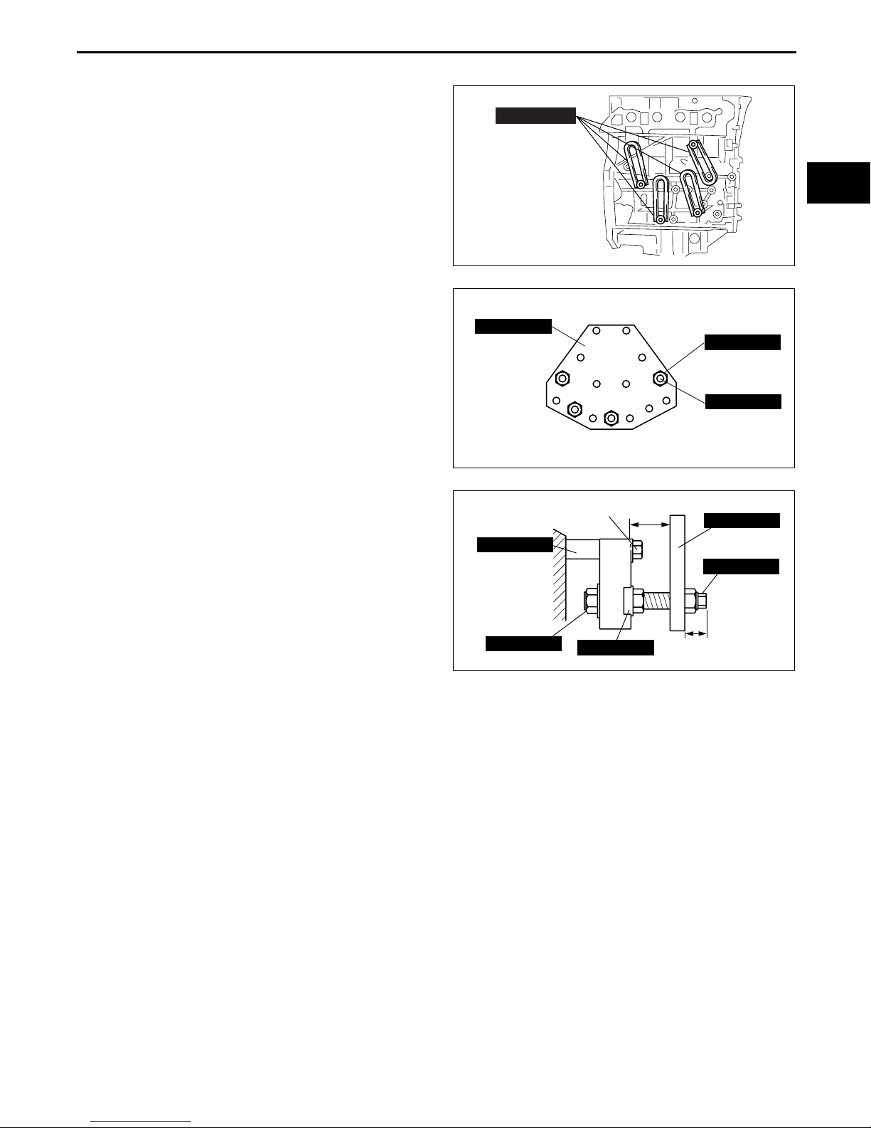
1. Install the SSTs (arms) to the cylinder block holes
as shown, and hand-tighten the bolts (part No.:
9YA20-1003) or M10 × 1.5T length 90 mm {3.55
in}.
2. Assemble the SSTs (bolts, nuts and plate) to the
specified positions.
3. Adjust the SSTs (bolts) so that less than 20 mm
{0.79 in} of thread is exposed.
4. Make the SSTs (arms and plate) parallel by
adjusting the SSTs (bolts and nuts).
5. Tighten the SSTs (bolts and nuts) to affix the
SSTs firmly.
Warning
• Self-locking brake system of the engine
stand may not be effective when the
engine is held in an unbalanced position.
This could lead to sudden, rapid
movement of the engine and mounting
stand handle and cause serious injury.
Never keep the engine in an unbalanced
position, and always hold the rotating
handle firmly when turning the engine.
49 L010 102
49 L010 101
49 L010 102
ENGINE
49 L010 104
PARALLEL
BOLT
49 L010 103
E5U011002000E02
01–10
B3E0110W127
49 L010 104
49 L010 105
C3U0110E001
49 L010 101
49 L010 105
APPROX. 20 mm {0.79 in}
E5U110ZW8S01
6. Mount the engine on the SST (engine stand).
7. Drain the engine oil into a container.
8. Install the oil pan drain plug.
• With washer
1. Install the oil pan drain plug with a new washer.
Tightening torque
30—41 N·m {3.1—4.1 kgf·m, 23—30 ft·lbf}
• Without washer
1. Inspect the seal rubber of the oil pan drain plug and make sure there are no cracks or damage.
— If necessary, replace the oil pan drain plug.
2. Clean the flange surface (seal rubber) on the oil pan drain plug, then install the oil pan drain plug.
Tightening torque
22—30 N·m {2.2—3.1 kgf·m, 16—22 ft·lbf}
DISMOUNTING
• Dismount in the reverse order of mounting.
End Of Sie
01–10–3
Page 18
MECHANICAL
TIMING CHAIN DISASSEMBLY
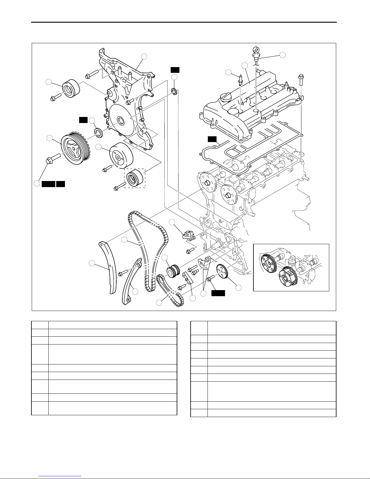
1. Disassemble in the order indicated in the table.
8
7
R
9
5
6
4
SST
R
WITHOUT A/C
.
E5U011002000E03
1
R
3
2
14
R
10
13
19
11
12
18
1 Oil level gauge (if equipped)
2 Spark plug
3 Cylinder head cover
4 Crankshaft pulley lock bolt
(See 01–10–5 Crankshaft Pulley Lock Bolt
Disassembly Note.)
5 Crankshaft pulley
6 Water pump pulley
7 Drive belt idler pulley (Without stretch-type A/C drive
belt)
8 Engine front cover
9 Front oil seal
(See 01–10–5 Front Oil Seal Disassembly Note.)
WITH VARIABLE VALVE TIMING
MECHANISM
17
SST
15
16
10 Chain tensioner
(See 01–10–5 Chain Tensioner Disassembly Note.)
11 Tensioner arm
12 Chain guide
13 Timing chain
14 Seal (With variable valve timing mechanism)
15 Oil pump chain tensioner
16 Oil pump chain guide
17 Oil pump sprocket
(See 01–10–5 Oil Pump Sprocket Disassembly
Note.)
18 Oil pump chain
19 Crankshaft sprocket
E5U110ZE7S01
01–10–4
Page 19
Engine Workshop Manual LF L3 (1866–1U–05H)
MECHANICAL
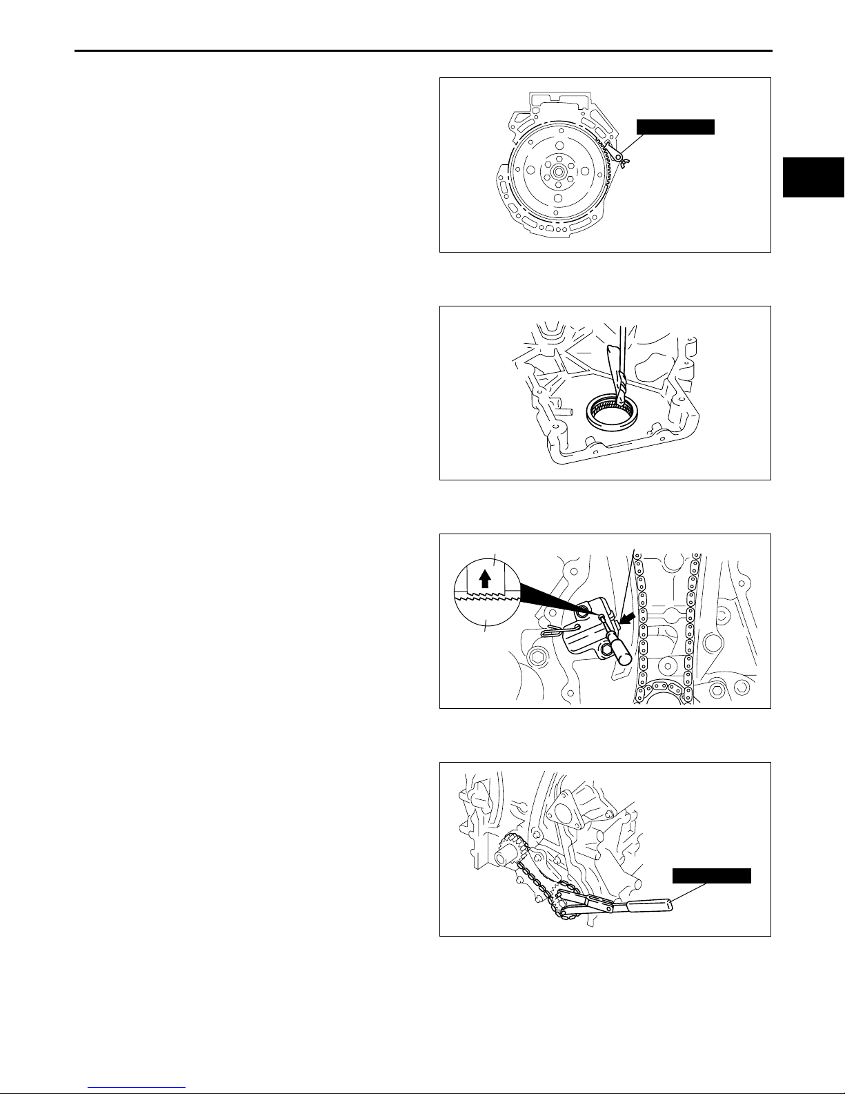
Crankshaft Pulley Lock Bolt Disassembly Note
1. Install the SST to the ring gear to lock the
crankshaft against rotation.
Front Oil Seal Disassembly Note
1. Remove the oil seal using a screwdriver.
49 E011 1A0
01–10
D3U110ZE4003
Chain Tensioner Disassembly Note
1. Unlock the chain tensioner ratchet using a
suitable screw driver or equivalent tool.
2. Slowly press the tensioner piston.
3. Hold the chain tensioner piston with a 1.5 mm
{0.06 in} wire or paper clip.
Oil Pump Sprocket Disassembly Note
1. Hold the oil pump sprocket using the SST.
End Of Sie
RATCHET
RACK
E6U110ZWB044
TENSIONER PISTON
C3U0110W098
49 G032 354
B3E0110E054
01–10–5
Page 20
Engine Workshop Manual LF L3 (1866–1U–05H)
MECHANICAL
CYLINDER HEAD (I) DISASSEMBLY
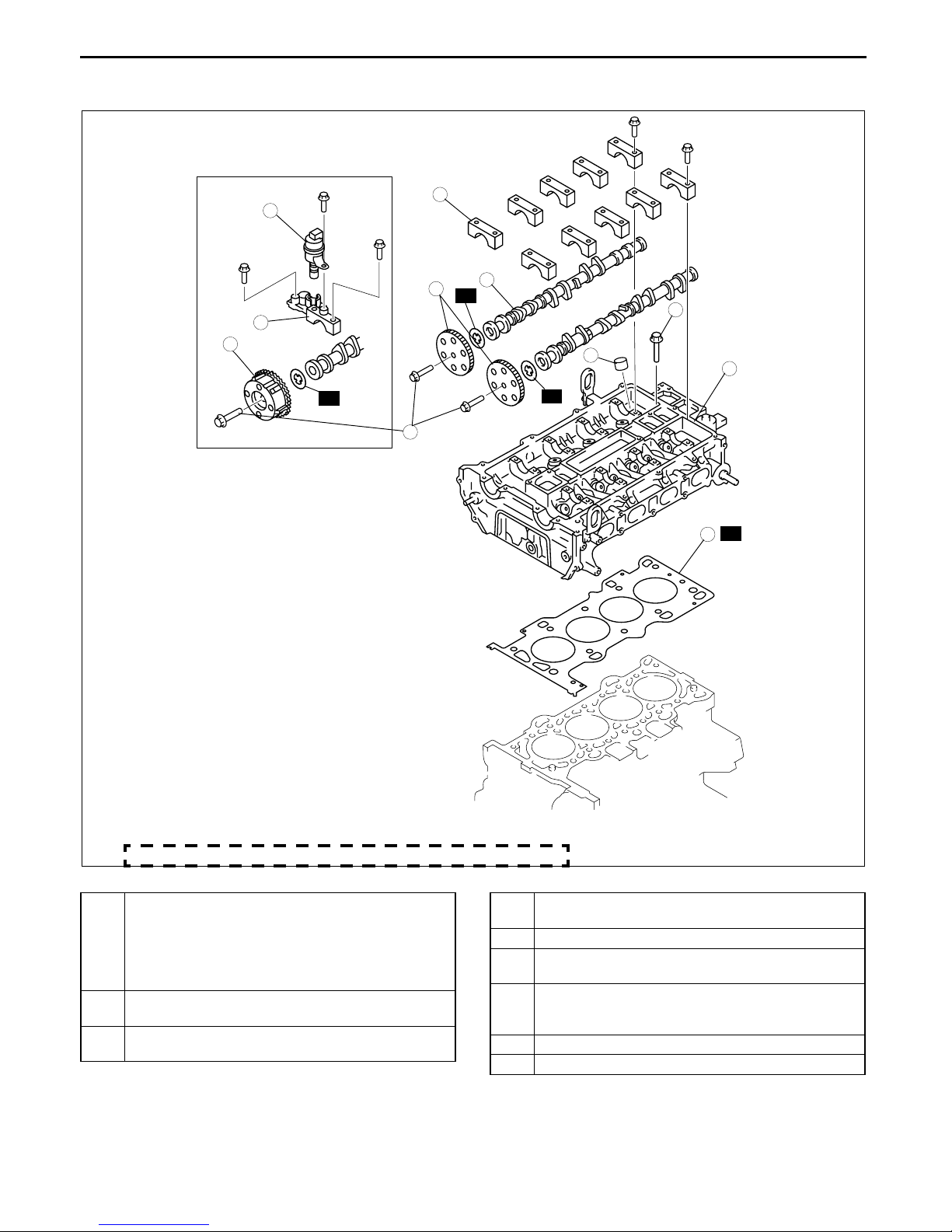
1. Disassemble in the order indicated in the table..
WITH VARIABLE VALVE TIMING MECHANISM
3
4
2
*
R
E5U011002000E04
4
5
*
2
R
7
6
8
*
R
1
*: IF WASHER IS NOT INSTALLED TO THE ENGINE, INSTALL A NEW WASHER.
1 Camshaft sprocket lock bolt, variable valve timing
actuator lock bolt (With variable valve timing
mechanism)
(See 01–10–7 Camshaft Sprocket Lock Bolt,
Variable Valve Timing Actuator Lock Bolt
Disassembly Note .)
2 Camshaft sprocket, variable valve timing actuator
(With variable valve timing mechanism)
3 Oil control valve (OCV) (with variable valve timing
mechanism)
R
9
4 Camshaft cap
(See 01–10–7 Camshaft Cap Disassembly Note.)
5 Camshaft
6 Tappet
(See 01–10–7 Tappet Disassembly Note.)
7 Cylinder head bolt
(See 01–10–8 Cylinder Head Bolt Disassembly
Note.)
8 Cylinder head
9 Cylinder head gasket
E5U110ZECL01
01–10–6
Revised 12/2005 (Ref. No. R145/05)
Page 21
MECHANICAL
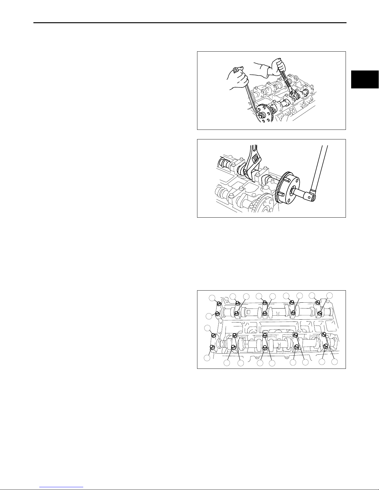
Camshaft Sprocket Lock Bolt, Variable Valve Timing Actuator Lock Bolt Disassembly Note
1. Hold the camshaft by using a wrench on the cast hexagon as shown, and loosen the camshaft sprocket
installation bolt or variable valve timing actuator installation bolt (With variable valve timing mechanism).
Without variable valve timing mechanism
With variable valve timing mechanism
01–10
B3E0110E056
Camshaft Cap Disassembly Note
1. Before removing the camshaft caps, inspect the following:
— Camshaft end play and camshaft journal oil clearance (See 01–10–15 CAMSHAFT INSPECTION.)
Note
• The camshaft caps are numbered to make sure they are assembled in their original positions. When
removed, keep the caps with the cylinder head they were removed from. Do not mix the caps.
2. Loosen the camshaft caps bolts in 2—3 steps in
the order shown in the figure.
1
5
9
6
10
8
7
2
12
11
15
16
19
20
17
Tappet Disassembly Note
18
B3E0110E058
43
1413
B3E0110E057
Note
• The tappets are numbered to make sure they are assembled in their original positions. When removed,
keep the tappets with the cylinder head they were removed from. Do not mix the tappets.
01–10–7
Page 22
MECHANICAL
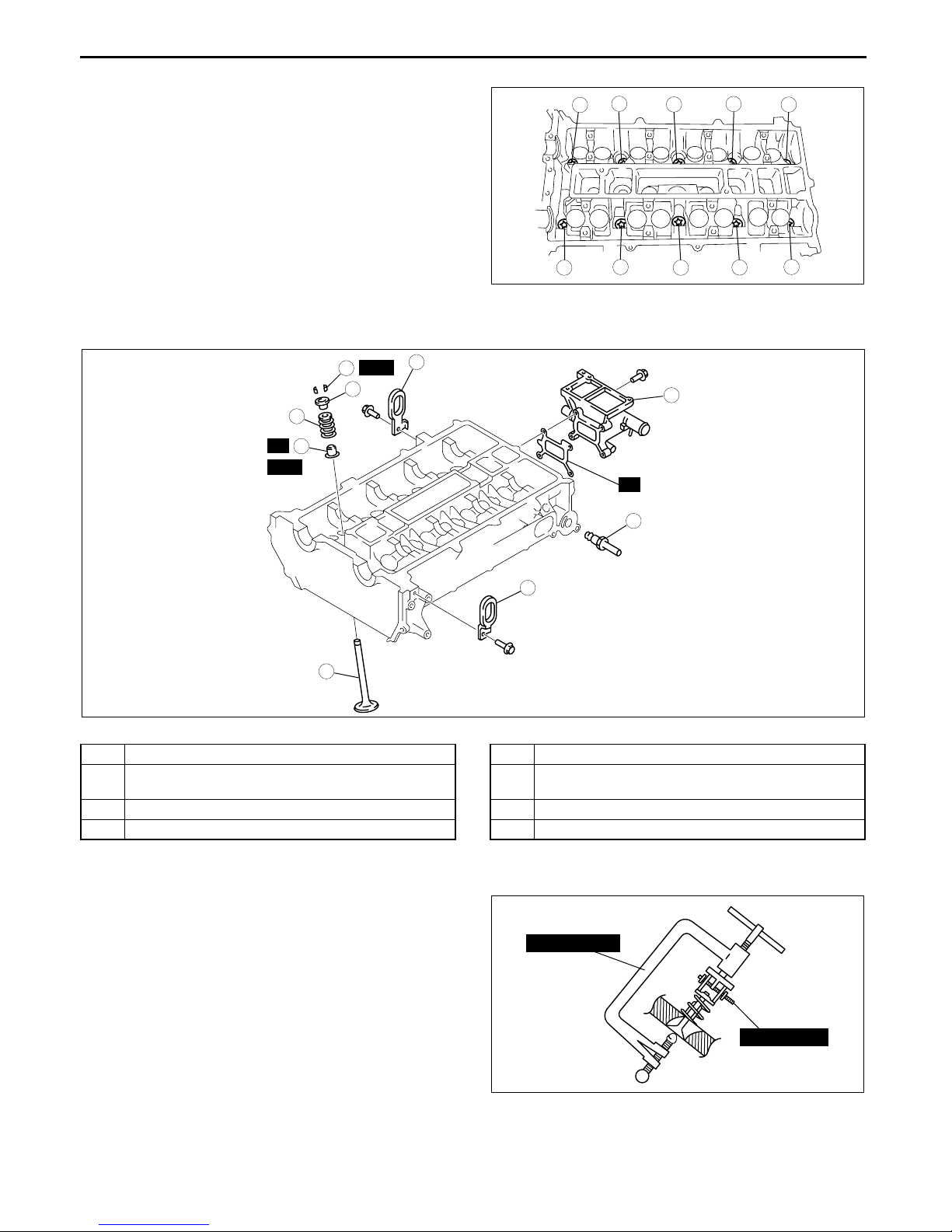
Cylinder Head Bolt Disassembly Note
1. Loosen the cylinder head bolts in 2—3 steps in
the order shown in the figure.
End Of Sie
7
3
10
6
2
CYLINDER HEAD (II) DISASSEMBLY
1. Disassemble in the order indicated in the table.
SST
2
3
4
6
R
SST
5
4
.
8
9
5
1
B3E0110E059
E5U011002000E05
1
8
R
7
1
1 Engine hanger
2 Valve keeper
(See 01–10–8 Valve Keeper Disassembly Note.)
3 Upper valve spring seat
4 Valve spring
Valve Keeper Disassembly Note
1. Remove the valve keeper using the SSTs.
B3E0110E060
5Valve
6 Valve seal
(See 01–10–9 Valve Seal Disassembly Note.)
7EGR pipe
8 Water outlet
49 0636 100B
49 B012 0A2
B3E0110E124
01–10–8
Page 23
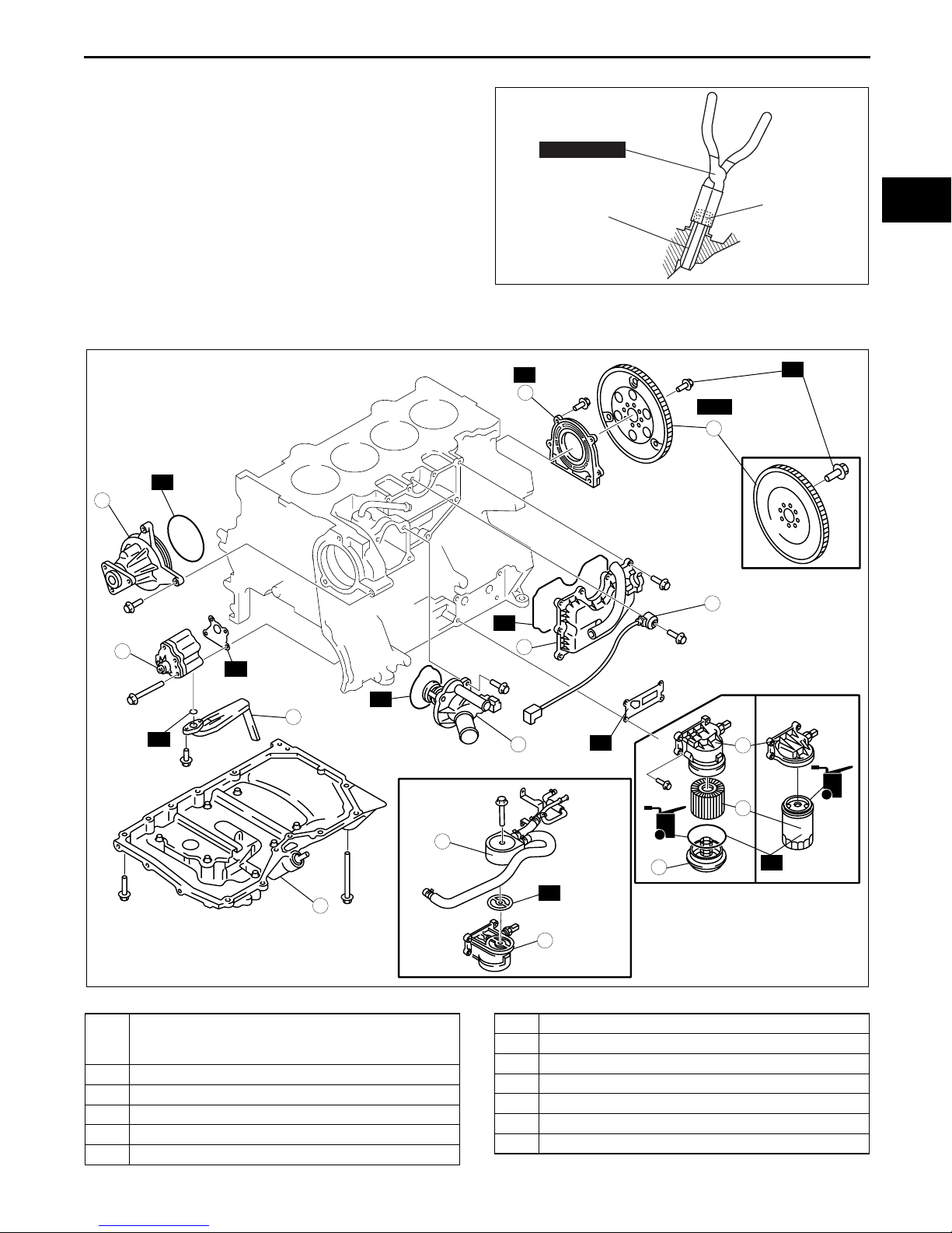
Valve Seal Disassembly Note
1. Remove the valve seal using the SST.
End Of Sie
MECHANICAL
49 S120 170
CYLINDER BLOCK (I) DISASSEMBLY
1. Disassemble in the order indicated in the table.
R
10
12
R
IF EQUIPPED
R
11
R
.
R
WITH OIL COOLER
VALVE GUIDE
R
13
8
9
VALVE SEAL
B3E0110E061
E5U011002000E06
01–10
R
SST
1
MTX
7
WITHOUT OIL COOLER
CARTRIDGE
TYPE
R
6
SPIN-ON
TYPE
OIL
2
1 Flywheel (MTX), Drive plate (ATX) (See 01–10–10
Drive Plate (ATX), Flywheel (MTX) Disassembly
Note)
2 Oil pan
3 Oil filter cover (cartridge type)
4 Oil filter
5 Oil cooler
6 Oil filter adapter
OIL
4
5
3
R
R
6
E5U110ZE7S10
7 Knock sensor
8 Oil separator
9 Thermostat
10 Water pump
11 Oil strainer
12 Oil pump
13 Rear oil seal
01–10–9
Page 24
MECHANICAL
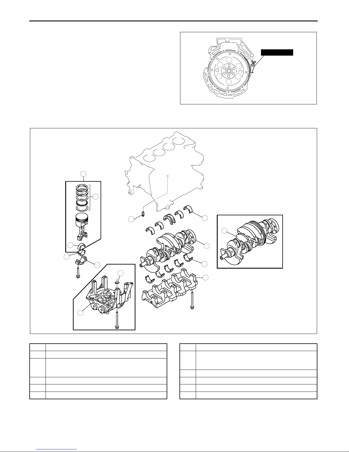
Drive Plate (ATX), Flywheel (MTX) Disassembly Note
1. Hold the crankshaft using the SST.
2. Remove the bolts in several passes.
End Of Sie
49 E011 1A0
1
3
6
CYLINDER BLOCK (II) DISASSEMBLY
1. Disassemble in the order indicated in the table.
5
6
12
5
4
2
B3E0110E051
.
L3
E5U011002000E07
11
10
7
4
L3
3
2
1
1 Balancer unit
2 Adjustment shim
3 Connecting rod cap
(See 01–10–11 Connecting Rod Cap Disassembly
Note.)
4 Lower connecting rod bearing
5 Connecting rod, Piston component
6 Piston ring
10
9
8
E5U110ZE7S07
7 Upper connecting rod bearing
8 Main bearing cap
(See 01–10–11 Main Bearing Cap Disassembly
Note.)
9 Lower main bearing, thrust bearing
10 Crankshaft
11 Upper main bearing, thrust bearing
12 Oil jet valve
01–10–10
Page 25
MECHANICAL
Connecting Rod Cap Disassembly Note
1. Before removing connecting rod inspect the connecting rod side clearance. (See 01–10–20 CONNECTING
ROD INSPECTION.)
2. Remove the connecting rod bolt from the connecting rod cap by tapping the bolt with a plastic hammer.
Note
• The tappets are numbered to make sure they are assembled in their original positions. When removed,
keep the tappets with the cylinder head they were removed from. Do not mix the tappets.
Main Bearing Cap Disassembly Note
1. Before removing main bearing cap inspect the crankshaft end play. (See 01–10–19 CRANKSHAFT
INSPECTION.)
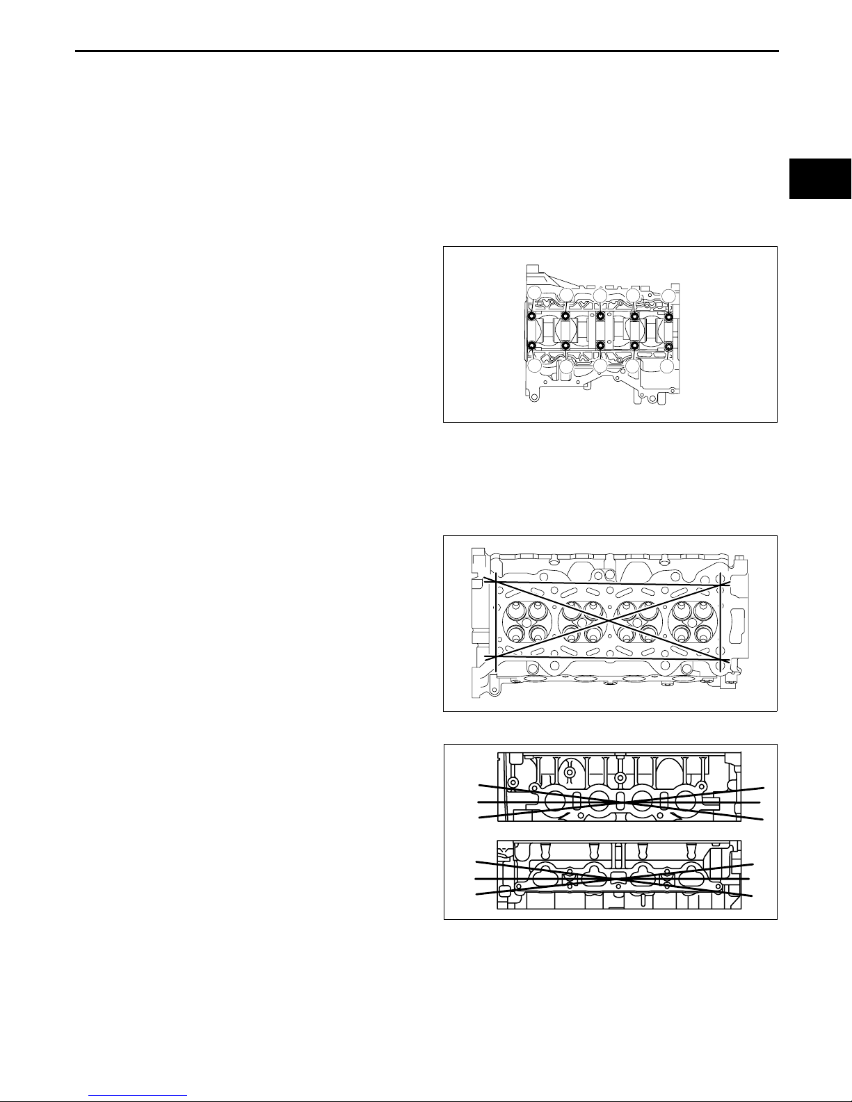
2. Loosen the main bearing cap bolts in two or three
steps in the order shown in the figure.
End Of Sie
2
6
10
8
4
01–10
1
CYLINDER HEAD INSPECTION
1. Perform color contrast penetrate examination on the cylinder head surface.
• Replace the cylinder head if necessary.
2. Inspect for the following and repair or replace if necessary.
(1) Sunken valve seats
(2) Excessive camshaft oil clearance and end play
3. Measure the cylinder head for distortion in six
directions as shown in the figure.
• If it exceeds the maximum specification,
replace the cylinder head.
Cylinder head gasket contact surface
distortion (Maximum)
0.10 mm {0.004 in}
4. Measure the manifold contact surface distortion
as shown in the figure.
EX
9
5
7
3
B3E0110E067
E5U011010100E01
B3E0110E008
• If it exceeds the maximum specification, grind the surface or replace the cylinder head.
Manifold contact surfaces distortion (Maximum)
0.10 mm {0.004 in}
Manifold contact surfaces distortion (Maximum grinding)
0.15 mm {0.006 in}
IN
C3U0110E003
01–10–11
Page 26
MECHANICAL
End Of Sie
VALVE, VALVE GUIDE INSPECTION
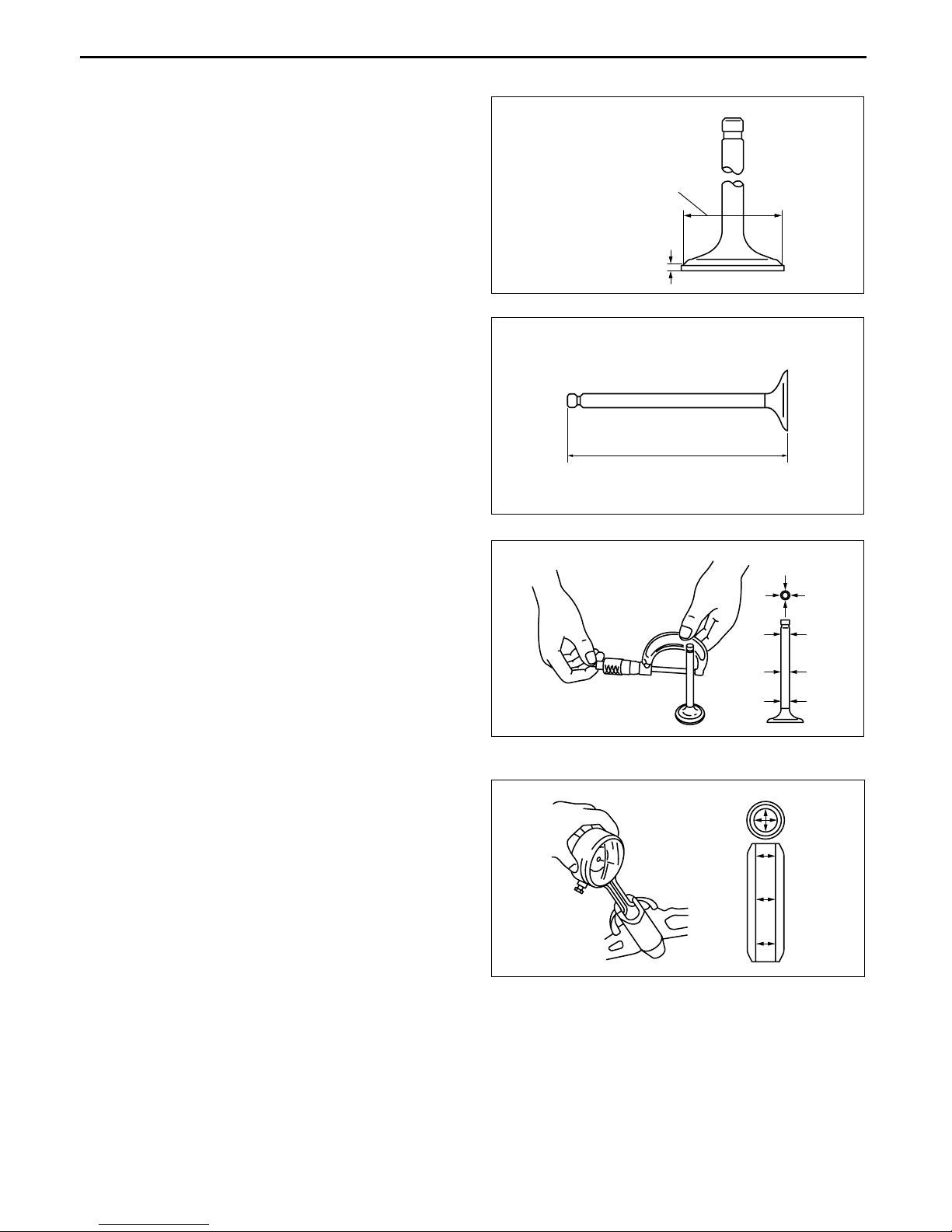
1. Measure the valve head margin thickness of each
valve.
• If it is less than the specification, replace the
valve.
Valve head margin thickness (Minimum)
IN: 1.62 mm {0.0637 in}
EX: 1.82 mm {0.0716 in}
2. Measure the length of each valve. Replace the
valve if necessary.
• If it is less than the specification, replace the
valve.
Valve length (Standard)
IN: 102.99—103.79 mm {4.055—4.086 in}
EX: 104.25—105.05 mm {4.105—4.135 in}
Valve length (Minimum)
IN: 102.99 mm {4.055 in}
EX: 104.25 mm {4.104 in}
3. Measure the stem diameter of each valve in X
and Y directions at the three points (A, B, and C)
as indicated in the figure.
• If it exceeds the specification, replace the
valve.
Valve stem diameter (Standard)
IN: 5.470—5.485 mm {0.2154—0.2159 in}
EX: 5.465—5.480 mm {0.2152—0.2157 in}
Valve stem diameter (Minimum)
IN: 5.440 mm {0.2142 in}
EX: 5.435 mm {0.2140 in}
E5U011012111E01
IN : 33.5 mm {1.31 in}
EX : 28.3 mm {1.14 in}
MARGIN THICKNESS
C3U0110E051
L
B3E0110E068
X
Y
A
B
C
ADJ2224E024
4. Measure the inner diameter of each valve guide in
X and Y directions at the three points (A, B, and
C) as indicated in the figure.
• If not as specified, replace the valve guide.
Valve guide inner diameter (Standard)
5.509—5.539 mm {0.2169—0.2180 in}
01–10–12
X
Y
A
B
C
ADJ2224E026
Page 27
MECHANICAL
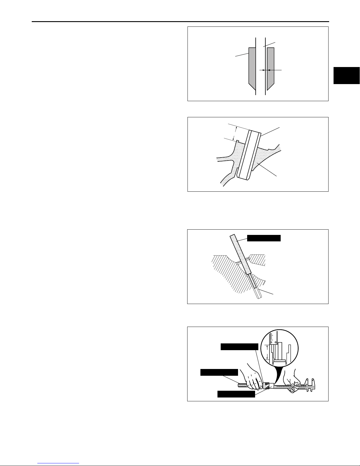
5. Calculate the valve stem to guide clearance by
subtracting the outer diameter of the valve stem
from the inner diameter of the corresponding
valve guide.
• If it exceeds the specification, replace the
valve and/or the valve guide.
Valve stem to guide clearance (Standard)
IN: 0.024—0.069 mm {0.0009—0.0027 in}
EX: 0.029—0.074 mm {0.0012—0.0029 in}
VALVE STEM
VALVE GUIDE
CLEARANCE
01–10
Valve stem to guide clearance (Maximum)
0.10 mm {0.004 in}
6. Measure the protrusion height (dimension A) of
each valve guide without lower valve spring seat.
• If not within the specified, replace the valve
guide.
Valve guide protrusion height (standard)
12.2—12.8 mm {0.481—0.503 in}
End Of Sie
VALVE GUIDE REPLACEMENT
Valve Guide Removal
1. Remove the valve guide from the combustion
chamber side using the SST.
ADA2224E027
VALVE GUIDE
A
CYLINDER HEAD
C3U0110E004
E5U011012111E02
49 B012 015
Valve Guide Installation
1. Assemble the SSTs so that depth L is as
specified.
Valve guide protrusion height (standard)
12.2—12.8 mm {0.481—0.503 in}
VALVE GUIDE
C3U0110E005
49 L012 004A
L
49 L012 003A
49 L012 002A
B3E0110E071
01–10–13
Page 28
MECHANICAL
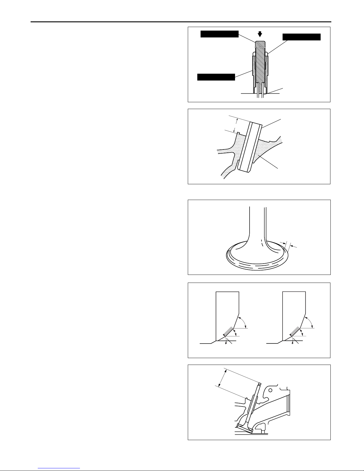
2. Tap the valve guide in from the top of the cylinder
head until the SSTs contacts the cylinder head.
3. Verify that the valve guide protrusion height
(dimension A) is within the specification.
Valve guide protrusion height (standard)
12.2—12.8 mm {0.481—0.503 in}
End Of Sie
VALVE SEAT INSPECTION/REPAIR
1. Measure the seat contact width.
• If not within the specification, resurface the
valve seat using a 45° valve seat cutter and/or
resurface the valve face.
49 L012 003A
49 L012 002A
49 L012 004A
VALVE GUIDE
B3E0110E072
VALVE GUIDE
A
CYLINDER HEAD
C3U0110E004
E5U011010102E01
Valve seat contact width (Standard)
1.2—1.6 mm {0.048—0.062 in}
2. Verify that the valve seating position is at the
center of the valve face.
(1) If the seating position is too out side, correct
the valve seat using a 70° (IN) or 65° (EX)
cutter, and a 45° cutter.
(2) If the seating position is too inner side, correct
the valve seat using a 35° (IN) cutter, and a
30° (EX) cutter, and a 45° cutter.
3. Inspect the sinking of the valve seat. Measure the
protruding length (dimension L) of the valve stem.
• If not specified, replace the cylinder head.
Valve protrusion height (Standard)
IN: 40.64—42.24 mm {1.600—1.662 in}
EX: 40.50—42.10 mm {1.595—1.657 in}
SEAT CONTACT
WIDTH
ADA2224E019
IN
70°
45°
35°
L
EX
65°
45°
30°
B3E0110E133
01–10–14
C3U0110E006
Page 29
MECHANICAL
End Of Sie
VALVE SPRING INSPECTION
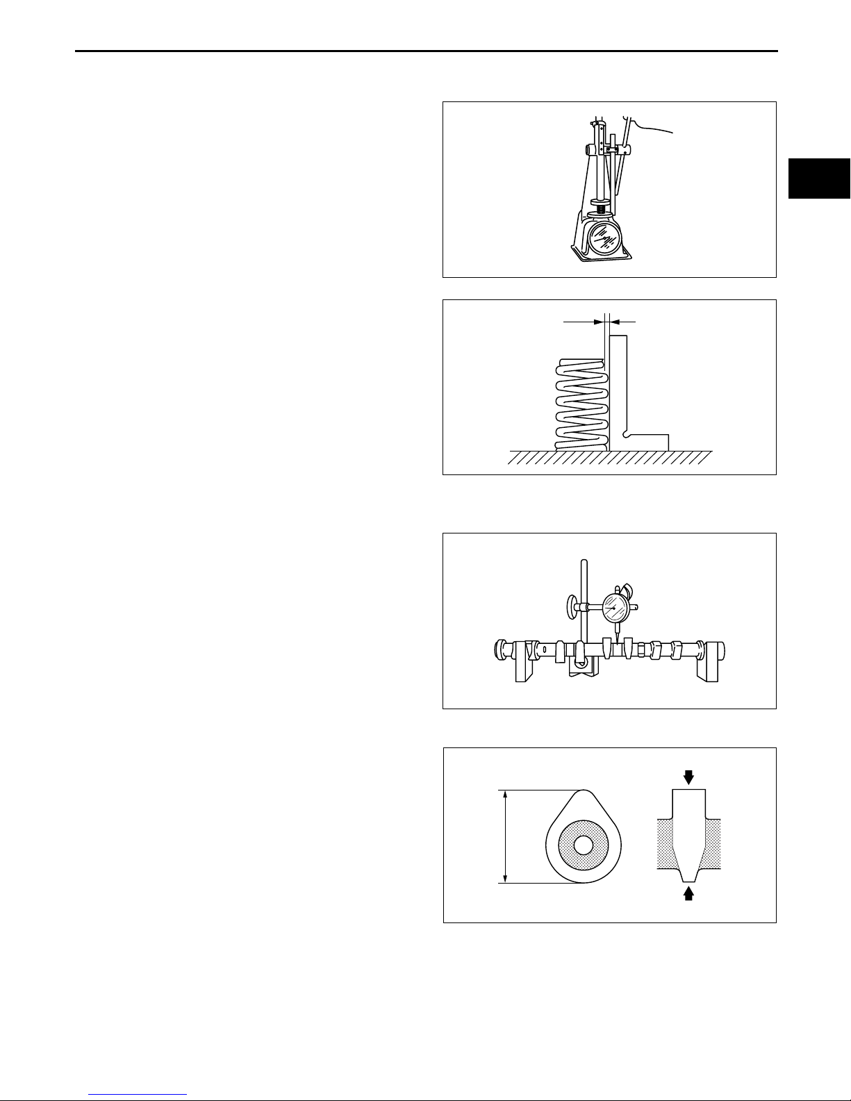
1. Apply pressing force to the pressure spring and inspect the spring height.
• If it is less than the specification, replace the
valve spring.
Valve spring pressing force
390 N {39.76 kgf, 87.67 lbf}
Valve spring standard height H
28.68 mm {1.129 in}
2. Measure the out-of-square of the valve spring,
using a square, as shown in the figure.
(1) Rotate the valve spring one full turn and
measure "A" at the point where the gap is the
largest.
• If it exceeds the specification, replace the
valve spring.
Valve spring out-of-square (Maximum)
1.95 mm {0.0767 in}
UPPER
LOWER
E5U011012125E01
01–10
ADJ2224E028
A
End Of Sie
CAMSHAFT INSPECTION
1. Set the No.1 and No.5 journals on V-blocks.
2. Measure the camshaft runout.
• If it exceeds the specification, replace the
camshaft.
Maximum runout (Maximum)
0.03 mm {0.0012 in}
3. Measure the cam lobe height at the two points as
shown in the figure.
• If it is less than the specification, replace the
camshaft.
Camshaft standard height (mm {in})
With variable valve timing mechanism
IN: 42.44 {1.671}
EX: 41.18 {1.621}
Without variable valve timing mechanism
IN: 42.12 {1.659}
EX: 41.08 {1.618}
Camshaft minimum height (mm {in})
With variable valve timing mechanism
IN: 42.33 {1.666}
EX: 41.06 {1.616}
Without variable valve timing mechanism
IN: 42.01 {1.653}
EX: 40.96 {1.612}
B3E0110E073
E5U011012420E01
B3E0110E074
B3E0110E076
01–10–15
Page 30
MECHANICAL
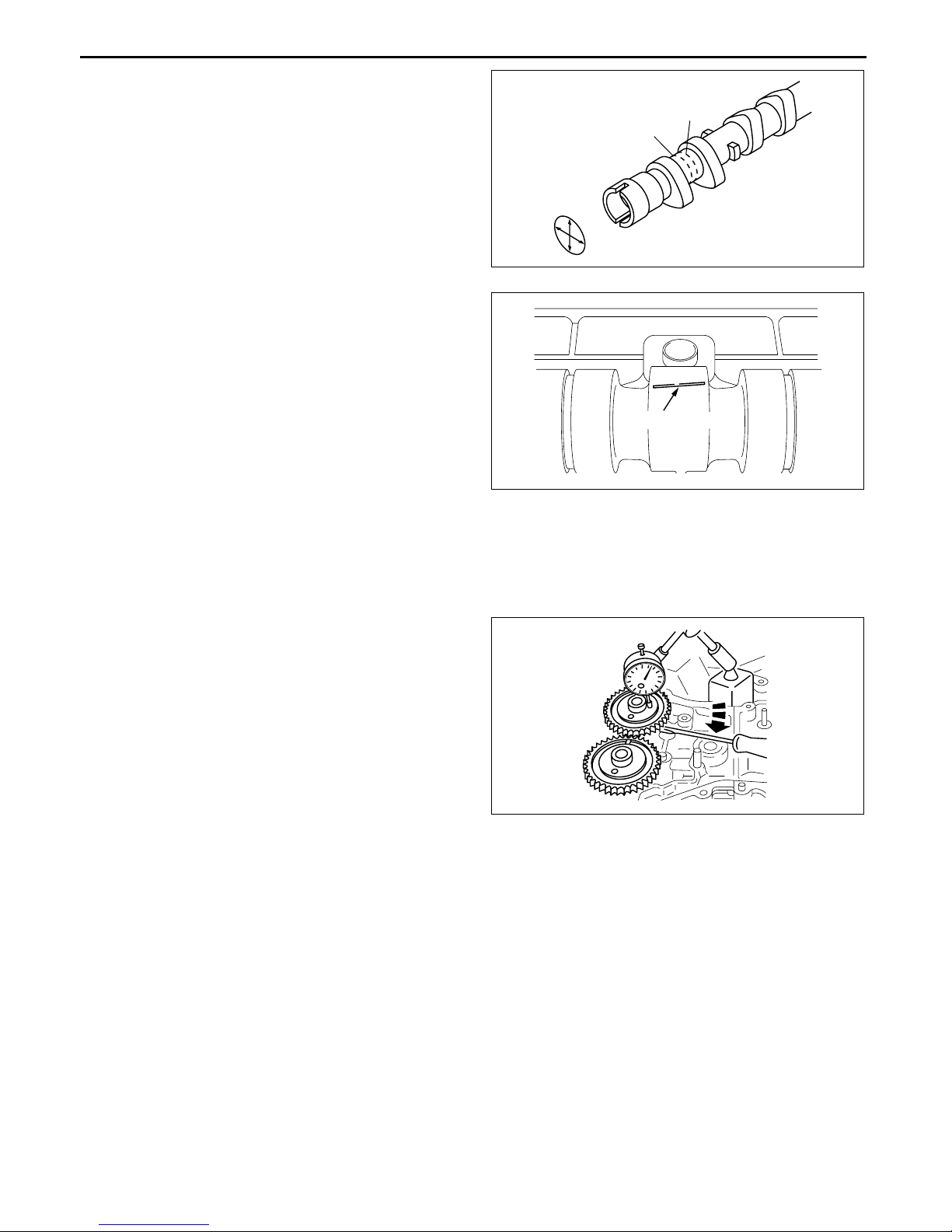
4. Measure the journal diameters in X and Y
directions at the two points (A and B) as indicated
in the figure.
• If it is less than the specification, replace the
camshaft.
Camshaft journal diameter (Standard)
24.96—24.98 mm {0.9827—0.9834 in}
Camshaft journal diameter (Minimum)
24.95 mm {0.982 in}
5. Remove the tappet.
6. Position a plastigage atop the journals in the axial
direction.
7. Install the camshaft cap. (See 01–10–37
Camshaft Assembly Note.)
8. Remove the camshaft cap. (See 01–10–7
Camshaft Cap Disassembly Note.)
9. Measure the oil clearance.
• If it exceeds the specification, replace the
cylinder head.
Camshaft journal oil clearance (Standard)
0.035—0.080 mm {0.0014—0.0031 in}
Camshaft journal oil clearance (Maximum)
0.09 mm {0.0035 in}
B
A
Y
X
B3E0110E075
PLASTIGAUGE
B3E0110E077
10. Install the camshaft cap. (See 01–10–37 Camshaft Assembly Note.)
11. Measure the camshaft end play.
• If it exceeds the specification, replace the cylinder head or camshaft.
Camshaft end play (Standard)
0.09—0.24 mm {0.0035—0.0094 in}
Camshaft end play (Maximum)
0.25 mm {0.0098 in}
12. Remove the camshaft cap. (See 01–10–7
Camshaft Cap Disassembly Note.)
End Of Sie
B3E0110E078
01–10–16
Page 31
MECHANICAL
TAPPET INSPECTION
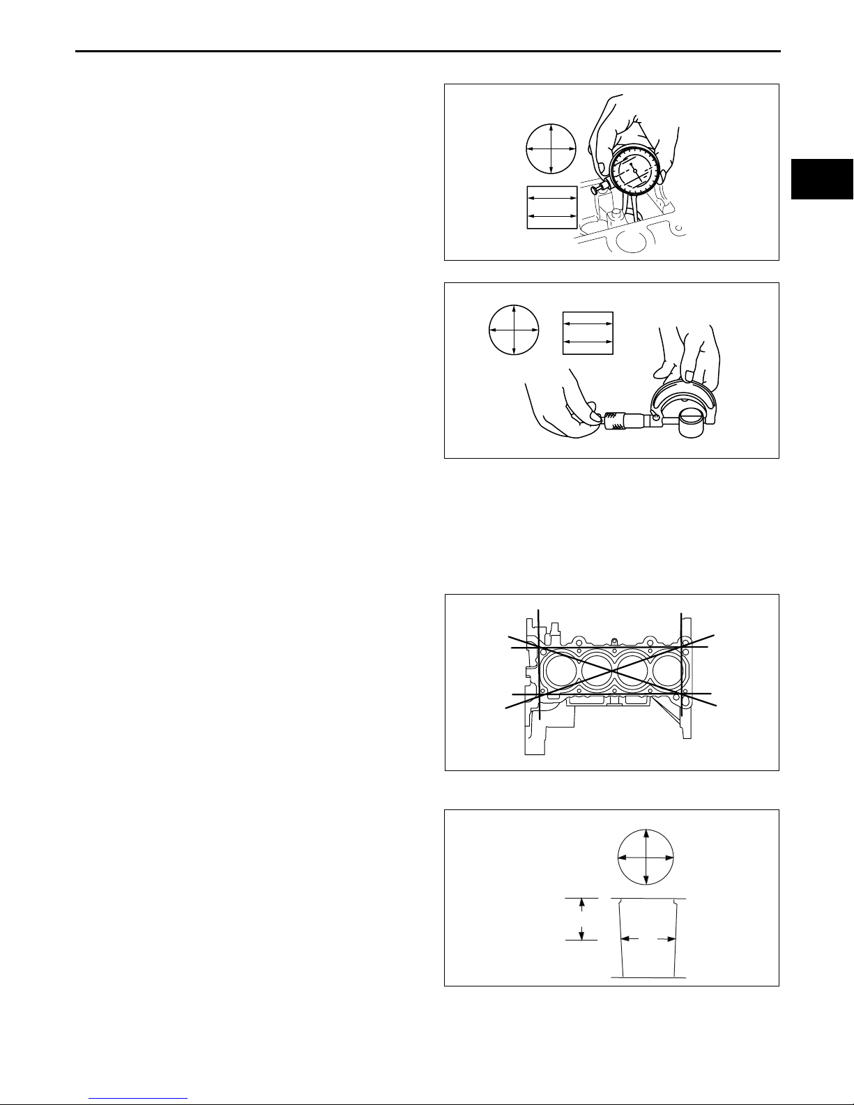
1. Measure the tappet hole inner diameter in X and
Y directions at the two points (A and B) shown in
the figure.
Tappet bore diameter (Standard)
31.000—31.030 mm {1.2205—1.2216 in}
2. Measure the tappet body outer diameter in X and
Y directions at the two points (A and B) shown in
the figure.
Tappet diameter (Standard)
30.970—30.980 mm {1.2193—1.2196 in}
3. Subtract the tappet body outer diameter from the
tappet hole inner diameter.
• If it exceeds the specification, replace the
tappet or cylinder head.
Tappet-to-Tappet bore oil clearance (Standard)
0.02—0.06 mm {0.0008—0.0023 in}
E5U011012431E01
X
Y
01–10
A
B
ADJ2224E023
Y
A
B
X
ADJ2224E029
Tappet-to-Tappet bore oil clearance (Maximum)
0.15 mm {0.006 in}
End Of Sie
CYLINDER BLOCK INSPECTION
1. Measure the distortion of the cylinder block top
surface in six directions as indicated in the figure.
• If it exceeds the maximum, replace the
cylinder block.
Cylinder head gasket contact surfaces
distortion (Maximum)
0.10 mm {0.004 in}
2. Measure the cylinder bores in X and Y directions
at 42 mm {1.65 in} below the top surface.
• If not within the specification, replace the
cylinder block.
Cylinder bore diameter (Standard)
87.500—87.530 mm {3.4449—3.4460 in}
Minimum / maximum bore diameter limit
87.440—87.590 mm {3.4425—3.4484 in}
E5U011010300E01
ADJ2224E089
X
Y
42 mm {1.65 in}
End Of Sie
C3U0110E007
01–10–17
Page 32
MECHANICAL
OIL JET VALVE INSPECTION
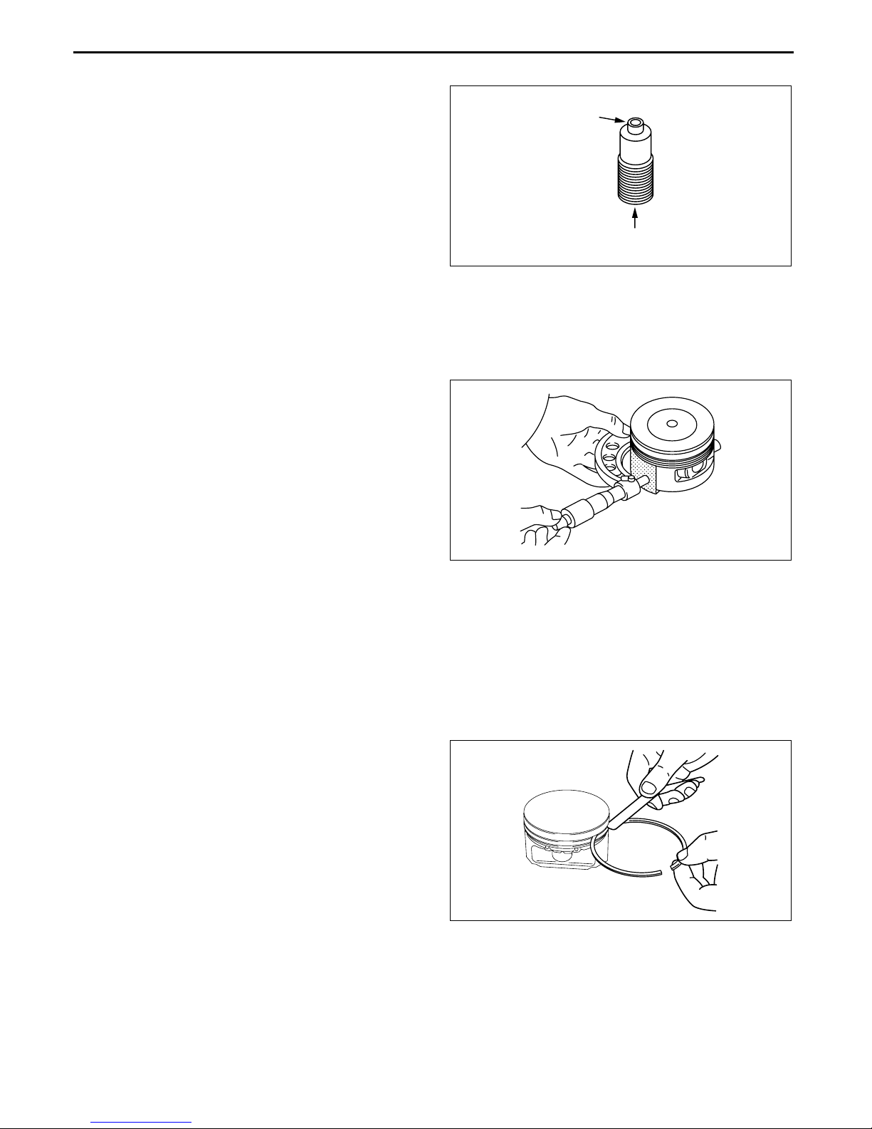
1. Apply compressed air to oil jet valve A and verify
that air passes through oil jet valve B.
• If air does not flow, replace the oil jet valve.
Oil jet valve air pressure
216—274 kPa {2.2—2.7 kgf·cm
2
31.4—39.7
B
psi}
End Of Sie
A
PISTON INSPECTION
Caution
• The piston and connecting rod cannot be disassembled.
• When replacing the piston, piston pin, piston ring and connecting rod, replace them together as a
single unit.
1. Measure the outer diameter of each piston at right
angle 90° to the piston pin, 10.0 mm {0.40 in}
above the under of the piston.
• If not within the specification, replace the
piston, piston pin, piston ring and connecting
rod as a single unit.
E5U011010730E01
B3E0110E079
E5U011011010E01
Piston diameter (Standard)
87.465—87.495 mm {3.4435—3.4446 in}
2. Measure the piston-to-cylinder clearance.
• If not within the specification, replace the
piston, piston pin, piston ring and connecting
rod as a single unit.
Piston-to-cylinder clearance (Standard)
0.025—0.045 mm {0.0010—0.0017 in}
Piston-to-cylinder clearance (Maximum)
0.11 mm {0.0043 in}
3. Measure the piston ring-to-ring groove clearance around the entire circumference.
• If it exceeds the specification, replace the piston, piston pin, piston ring and connecting rod as a single unit.
Piston ring-to-ring groove clearance
(Standard)
Top: 0.03—0.08 mm {0.0012—0.0031 in}
Second: 0.03—0.07 mm {0.0012—0.0027 in}
Oil: 0.03—0.07 mm {0.0012—0.0027 in}
Piston ring-to-ring groove clearance
(Maximum)
Top: 0.17 mm {0.0067 in}
Second, Oil: 0.15 mm {0.0059 in}
B3E0110E080
B3E0110E081
01–10–18
Page 33
MECHANICAL
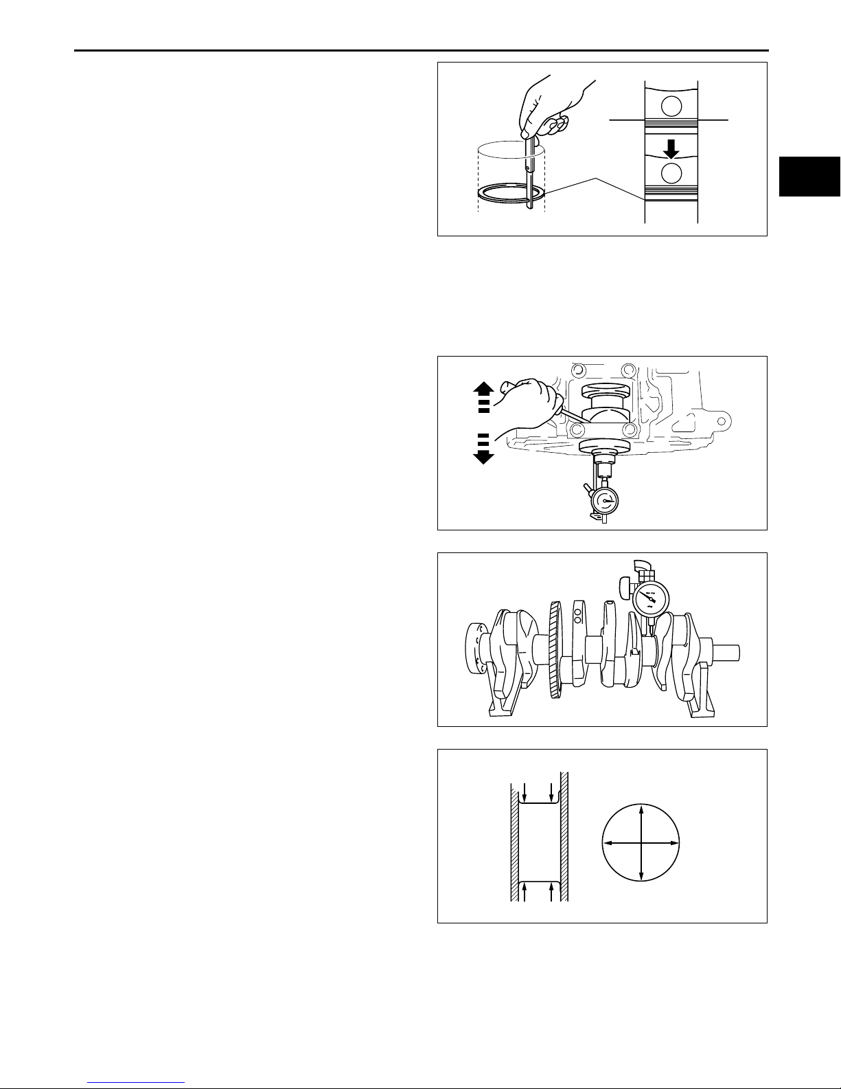
4. Insert the piston ring into the cylinder by hand and
use the piston to push it to the bottom of the ring
travel.
5. Measure each piston ring end gap with a feeler
gauge.
• If it exceeds the specification, replace the
piston, piston pin, piston ring and connecting
rod as a single unit.
Piston end gap (Standard)
Top: 0.16—0.31 mm {0.0063—0.0122 in}
Second: 0.33—0.48 mm {0.0130—0.0189 in}
Oil (rail): 0.20—0.70 mm {0.0079—0.0275 in}
Piston end gap (Maximum)
1.0 mm {0.0393 in}
End Of Sie
CRANKSHAFT INSPECTION
1. Install the main bearing cap. (See 01–10–28 Main Bearing Cap Assembly Note.)
2. Measure the crankshaft end play.
• If it exceeds the specification, replace the
thrust bearing or crankshaft so that the
specified end play is obtained.
Crankshaft end play (Standard)
0.22—0.45 mm {0.0087—0.0177 in}
PISTON RING
01–10
B3E0110E082
E5U011011301E01
Crankshaft end play (Maximum)
0.55 mm {0.0216 in}
3. Remove the main bearing cap. (See 01–10–11
Main Bearing Cap Disassembly Note.)
4. Measure the crankshaft runout.
• If it exceeds the specification, replace the
crankshaft.
Crankshaft runout (Maximum)
0.05 mm {0.0019 in}
5. Measure the journal diameter in X and Y
directions at the two points (A and B) as indicated
in the figure.
• If it exceeds the specification, replace the
crankshaft or grind the journal and install the
undersize bearing.
Main journal bearing size
STD: 51.980—52.000 mm {2.0464—2.0472
in}
US0.25: 51.730—51.750 mm {2.0366—2.0373
in}
Main journal out of round (Maximum)
0.05 mm {0.0019 in}
Crank pin journal diameter [LF]
STD: 46.980—47.000 mm {1.8497—1.8503
in}
US0.25: 46.730—46.750 mm {1.8398—1.8405
in}
Crank pin journal diameter [L3]
STD: 49.980—50.000 mm {1.9677—1.9685 in}
US0.25: 49.730—49.750 mm {1.9579—1.9586 in}
Crank pin out of round (Maximum)
0.05 mm {0.0019 in}
B3E0110E083
AME2224E311
AB
X
Y
B3E0110E085
01–10–19
Page 34
MECHANICAL
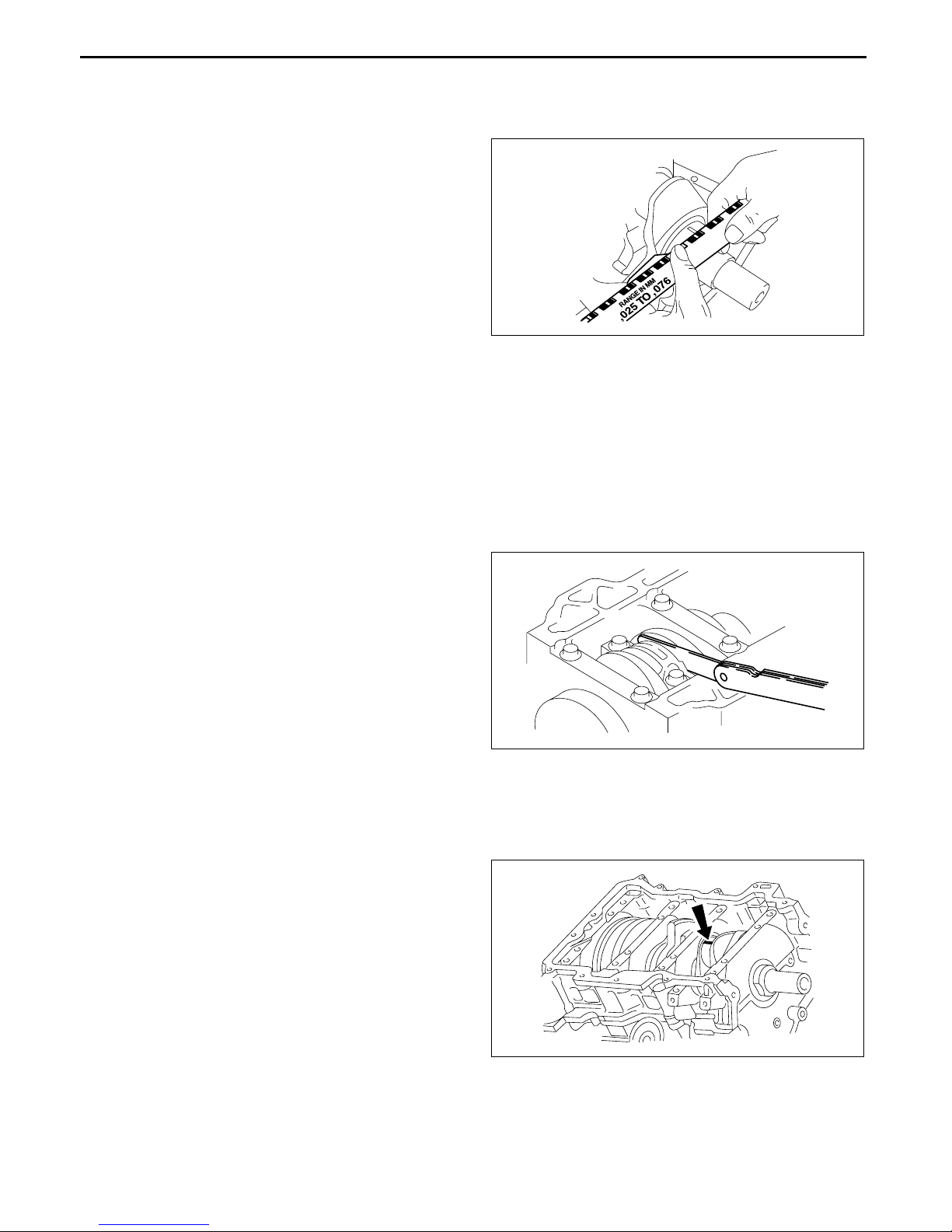
6. Install the main bearing caps and crankshaft.
7. Position a plastigage atop the journals in the axial direction.
8. Install the main bearing caps and cylinder block. (See 01–10–28 Main Bearing Cap Assembly Note.)
9. Remove the main bearing caps. (See 01–10–11 Main Bearing Cap Disassembly Note.)
10. Measure the main journal oil clearance.
• If it exceeds the specification, replace the
main bearing using the main bearing
selection table or grind the main journal and
install the oversize bearings so that the
specified oil clearance is obtained.
Main journal oil clearance (Standard)
0.019—0.035 mm {0.0007—0.0013 in}
Main journal oil clearance (Maximum)
0.10 mm {0.0039 in}
Main bearing size
STD: 2.506—2.509 mm {0.0987—0.0988 in}
OS0.25: 2.628—2.634 mm {0.1034—0.1037 in}
End Of Sie
CONNECTING ROD INSPECTION
Caution
• The piston and connecting rod cannot be disassembled.
• When replacing the piston, piston pin, piston ring and connecting rod, replace them together as a
single unit.
B3E0110E086
E5U01101 1211E01
1. Install the connecting rod cap. (See 01–10–29 Connecting Rod Cap Assembly Note.)
2. Measure the connecting rod large end side
clearance.
• If it exceeds the specification, replace the
piston, piston pin, piston ring and connecting
rod as a single unit.
Connecting rod side clearance (Standard)
0.14—0.36 mm {0.0056—0.0141 in}
Connecting rod side clearance (Maximum)
0.435 mm {0.0172 in}
3. Remove the connecting rod cap.
B3E0110E087
4. Position plastigage atop the journals in the axial
direction.
5. Install the connecting rod bearing and connecting rod cap. (See 01–10–29 Connecting Rod Cap Assembly
Note.)
6. Remove the connecting rod cap.
7. Measure the connecting rod oil clearance.
• If it exceeds the specification, replace the
connecting rod bearing or grind the crank pin
and use oversize bearings so that the
specified clearance is obtained.
Connecting rod bearing oil clearance
(Standard)
0.026—0.052 mm {0.0011—0.0020 in}
Connecting rod bearing oil clearance
(Maximum)
0.1 mm {0.0039 in}
Connecting rod bearing size [LF]
B3E0110W128
STD: 1.498—1.504 mm {0.0589—0.0592 in}
OS0.25: 1.623—1.629 mm {0.0639—0.0641 in}
Connecting rod bearing size [L3]
STD: 1.496—1.502 mm {0.0589—0.0591 in}
OS0.25: 1.621—1.627 mm {0.0639—0.0641 in}
01–10–20
Page 35
MECHANICAL
End Of Sie
BOLT INSPECTION
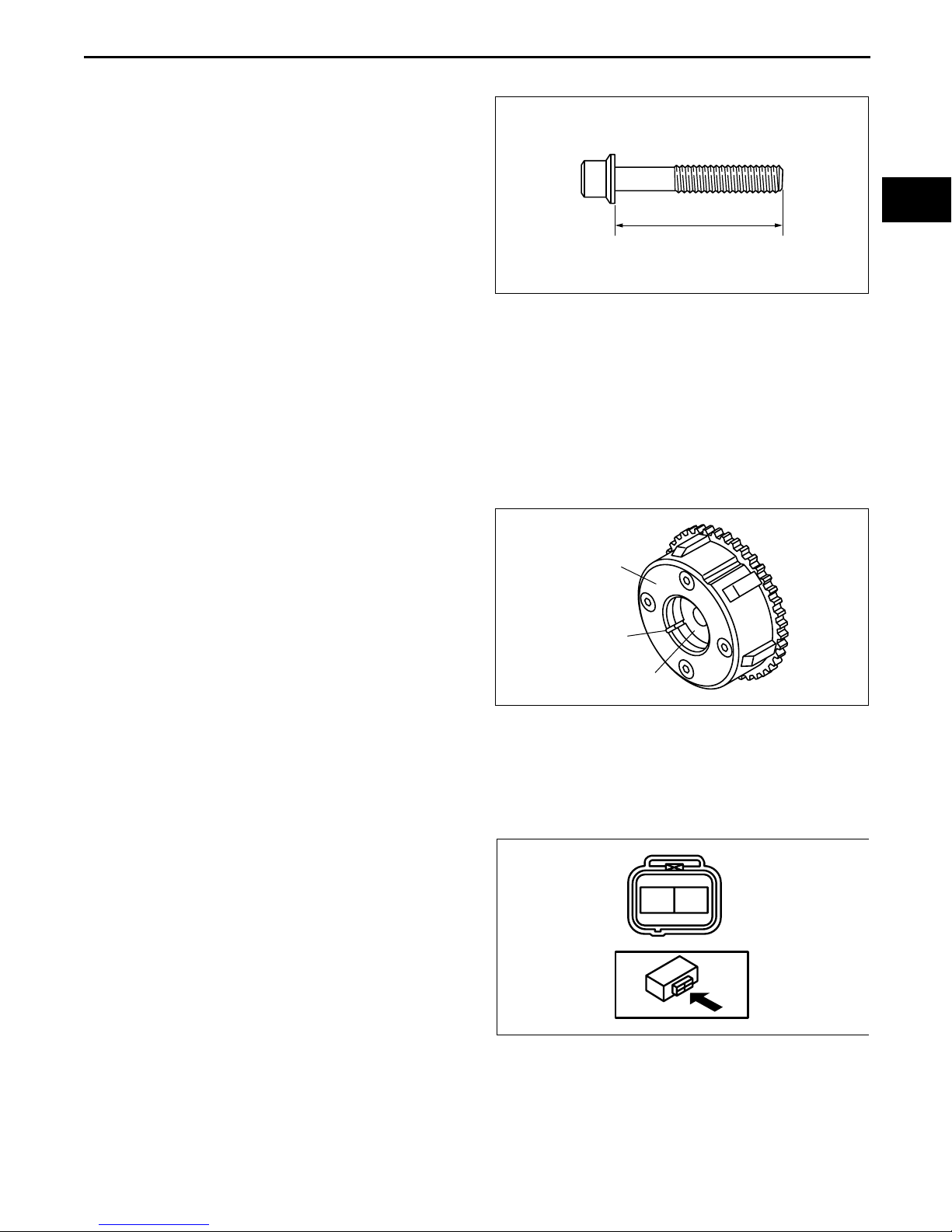
1. Measure the length of each bolt.
• If it exceeds the specification, replace the bolt.
Bolt length (mm {in})
Cylinder head bolt (With washer)
Standard: 149.2—149.8 {5.87—5.90}
Maximum: 150.5 {5.91}
Cylinder head bolt (Without washer)
L
Standard: 145.2—145.8 {5.72—5.74}
Maximum: 146.5 {5.77}
Connecting rod bolt
Standard: 44.7—45.3 {1.75—1.78}
Maximum: 46.0 {1.81}
Main bearing cap bolt (Plastic region
tightening bolt only)
Standard: 110.0—110.6 {4.33—4.35}
Maximum: 111.3 {4.38}
End Of Sie
VARIABLE VALVE TIMING ACTUATOR INSPECTION [WITH VARIABLE VALVE TIMING MECHANISM]
Caution
• Variable valve timing actuator cannot be disassembled because it is a precision unit.
E5U011010135E01
E5U011012490E01
01–10
B3E0110E088
1. Confirm that the groove of the rotor and notch of
the cover at the variable valve timing actuator are
aligned and fixed.
• If the notch and the bump are not aligned,
COVER
rotate the rotor toward the valve timing retard
position by hand until they are in place.
• If the rotor and cover are not fixed even
though their notch and groove are aligned,
NOTCH
replace the variable valve timing actuator.
End Of Sie
ROTOR
OIL CONTROL VALVE (OCV) INSPECTION [WITH VARIABLE VALVE TIMING MECHANISM]
Coil Resistance Inspection
1. Disconnect the negative battery cable.
2. Disconnect the oil control valve (OCV) connector.
3. Measure the resistance between terminals A and B using an ohmmeter.
• If not as specified, replace the oil control valve (OCV).
Specification
6.9—7.9 ohms [20 °C {68 °F}]
4. Connect the oil control valve (OCV) connector.
AB
B3E0110E089
E5U011014420E01
B3E0110W151
01–10–21
Page 36
MECHANICAL
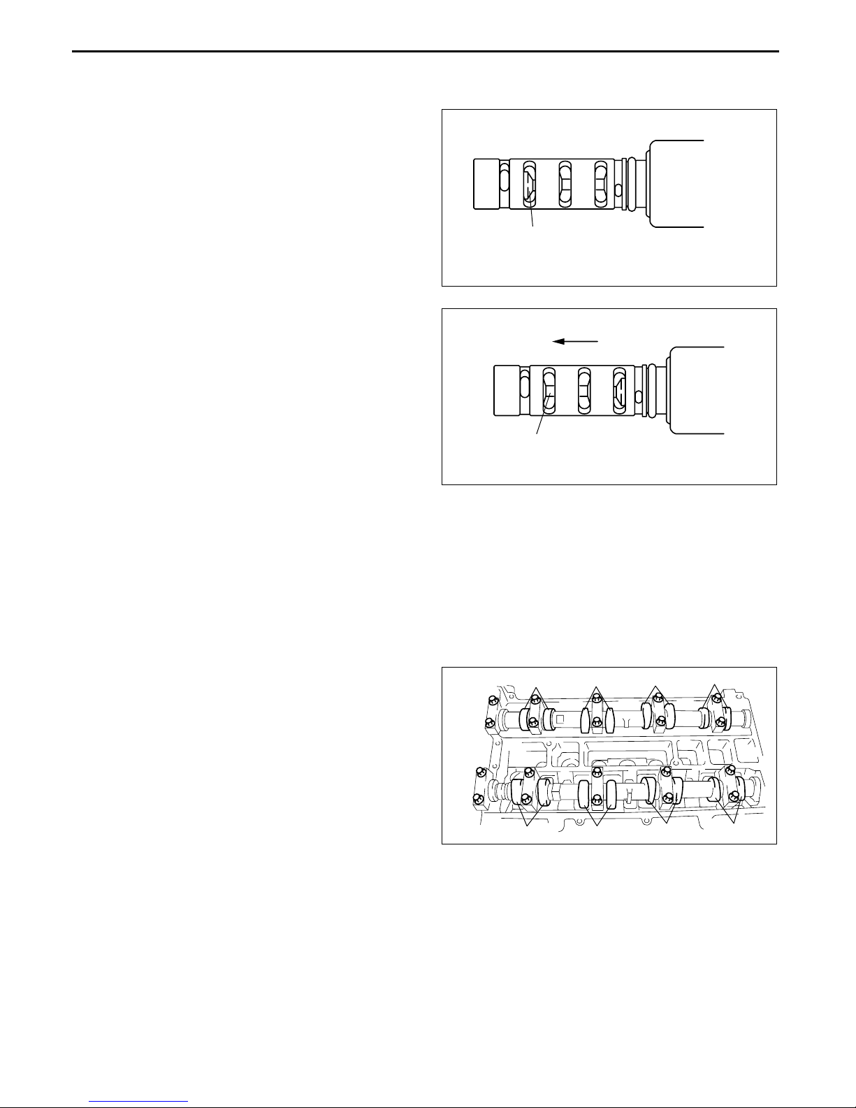
Spool Valve Operation Inspection
1. Disconnect the negative battery cable.
2. Remove the oil control valve (OCV).
3. Verify that the spool valve in the oil control valve
(OCV) is in the maximum valve timing retard
position as indicated in the figure.
• If it exceeds the specification, replace the oil
control valve (OCV).
4. Verify that the battery is fully charged.
• If it is less than specification, recharge the
battery.
5. Apply battery positive voltage between the oil
control valve (OCV) terminals and verify that the
spool valve operates and moves to the maximum
valve timing advance position.
• If it exceeds the specification, replace the oil
control valve (OCV).
Note
• When applying battery positive voltage
between the oil control valve (OCV)
terminals, the connection can be either of
the following:
— Positive battery cable to terminal A,
negative battery cable to terminal B
— Positive battery cable to terminal B, negative battery cable to terminal A
SPOOL VALVE
(MAXIMUM VALVE TIMING RETARD POSITION
VALVE TIMING
ADVANCE
SPOOL VALVE
(MAXIMUM VALVE TIMING ADVANCE POSITION)
VALVE TIMING
RETARD
B3E0110E090
B3E0110E091
6. Stop applying battery positive voltage and verify that the spool valve returns to the maximum valve timing retard
position.
• If it exceed the specification, replace the oil control valve (OCV).
End Of Sie
VALVE CLEARANCE INSPECTION
1. Measure the valve clearance as follows.
(1) Turn the crankshaft clockwise so that the No.1 piston is at TDC of the compression stroke.
(2) Measure the valve clearance at A in the
figure.
• If the valve clearance exceeds the
standard, replace the tappet. (See 01–
A
EX
B
10–23 VALVE CLEARANCE
ADJUSTMENT.)
Note
• Make sure to note the measured values for
IN
choosing the suitable replacement tappets.
Valve clearance [Engine cold]
A
A
IN: 0.22—0.28 mm {0.0087—0.0110 in}
EX: 0.27—0.33 mm {0.0106—0.0130 in}
(3) Turn the crankshaft 360° clockwise so that the No.4 piston is at TDC of the compression stroke.
(4) Measure the valve clearance at B in the figure.
• If the valve clearance exceeds the standard, replace the tappet. (See 01–10–23 VALVE CLEARANCE
ADJUSTMENT.)
A
B
E5U011012111E03
B
B
B3E0110E092
Note
• Make sure to note the measured values for choosing the suitable replacement tappets.
Valve clearance [Engine cold]
IN: 0.22—0.28 mm {0.0087—0.0110 in}
EX: 0.27—0.33 mm {0.0106—0.0130 in}
01–10–22
Page 37
MECHANICAL
End Of Sie
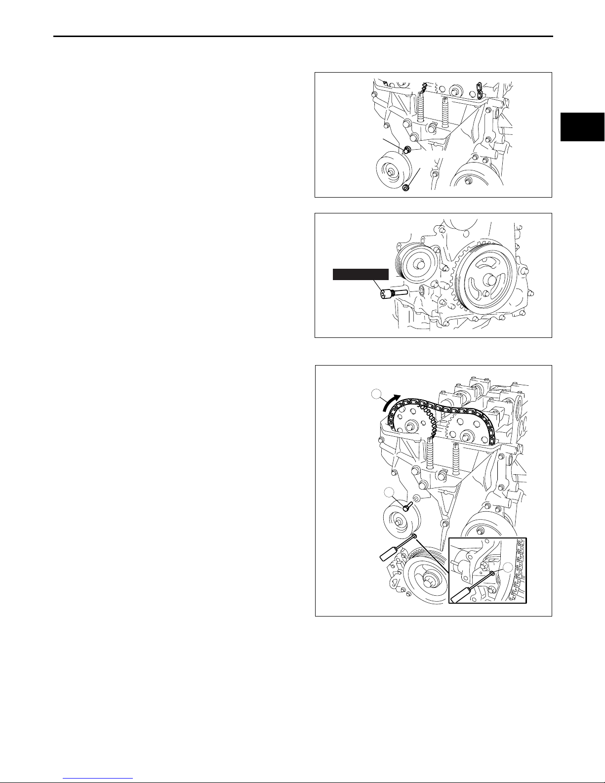
VALVE CLEARANCE ADJUSTMENT
1. Remove the engine front cover lower blind plug.
2. Remove the engine front cover upper blind plug.
3. Remove the cylinder block lower blind plug.
E5U011012111E04
4. Install the SST as shown in the figure.
Caution
• Removal of this SST is extremely
important. If you crank the engine with
this SST installed, the cylinder block will
be damaged.
5. Turn the crankshaft clockwise so that the
crankshaft is in the No.1 cylinder TDC position.
6. Loosen the timing chain.
(1) Using a suitable screwdriver or equivalent
tool, unlock the chain tensioner ratchet.
(2) Turn the exhaust camshaft clockwise using a
suitable wrench on the cast hexagon and
loosen the timing chain.
(3) Placing the suitable bolt (M6 × 1.0 Length
25—35 mm {0.9—1.3 in}) at the engine front
cover upper blind plug, secure the chain guide
at the position where the tension is released.
UPPER
BLIND
PLUG
303-507
01–10
LOWER BLIND
PLUG
B3E0110E093
D3U110ZE4006
2
BOLT (M6 x 1.0)
3
1
B3E0110E096
01–10–23
Page 38

MECHANICAL
7. Hold the exhaust camshaft using a suitable
wrench on the cast hexagon as shown in the
figure.
8. Remove the exhaust camshaft sprocket.
9. Loosen the camshaft cap bolts in several passes
in the order shown in the figure.
EXHAUST
CAMSHAFT
SPROCKET
1
5
B3E0110E095
B3E0110E097
10
7
9
6
8
43
Note
• The cylinder head and the camshaft caps
are numbered to make sure they are
reassembled in their original position. When
2
12
removed, keep the caps with the cylinder
head they were removed from. Do not mix
the caps.
10. Remove the camshaft.
11
15
16
19
20
17
11. Remove the tappet.
12. Select proper adjustment shim.
New adjustment shim
= Removed shim thickness + Measured valve clearance - Standard valve clearance (IN: 0.25 mm
{0.0098 in}, EX: 0.30 mm {0.0118 in})
Valve clearance [Engine cold]
IN: 0.22—0.28 mm {0.0087—0.0110 in}
EX: 0.27—0.33 mm {0.0106—0.0130 in}
13. Install the camshaft with No.1 cylinder aligned with the TDC position.
14. Tighten the camshaft cap bolt using the following
two steps.
Tightening torque
(1) 5.0—9.0 N·m
{51.0—91.7 kgf·cm, 44.3—79.5 in·lbf}
(2)14.0—17.0 N·m
10
20
9
5
1
6
3
2
{1.43—1.73 kgf·m, 10.4—12.5 ft·lbf}
18
7
4
1413
B3E0110E057
8
01–10–24
19
15
16
11
12
13
14
17
18
B3E0110E098
Page 39
Engine Workshop Manual LF L3 (1866–1U–05H)
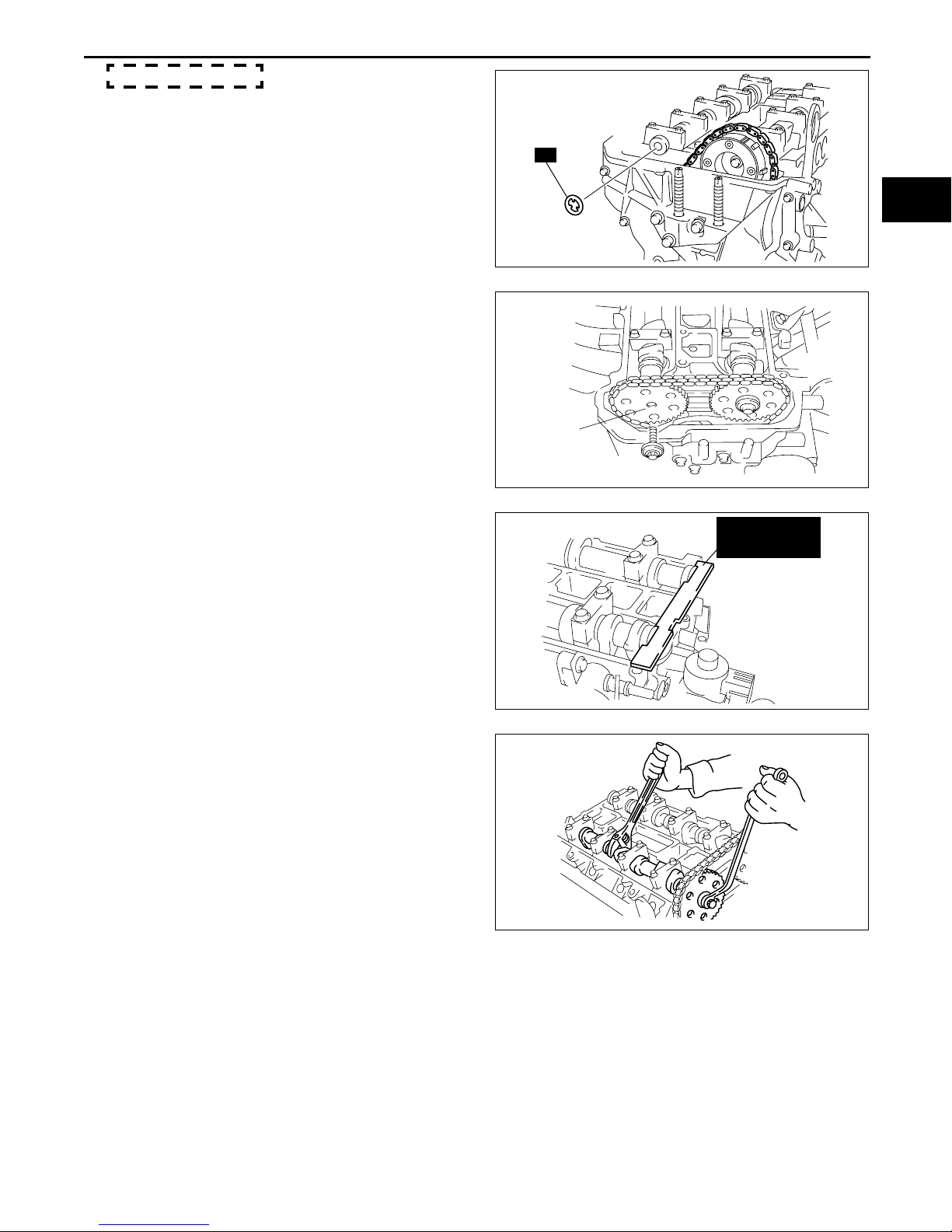
15. Install a new washer.
16. Install the exhaust camshaft sprocket.
Note
• Do not tighten the bolt for the camshaft
sprocket during this step. First confirm the
valve timing, then tighten the bolt.
MECHANICAL
R
01–10
D3U110ZE4012
EXHAUST
CAMSHAFT
SPROCKET
17. Install the SST to the camshaft as shown in the
figure.
18. Remove the M6 × 1.0 bolt from the engine front
cover to apply tension to the timing chain.
19. Turn the crankshaft clockwise so that the
crankshaft is in the No.1 cylinder TDC position.
20. Hold the exhaust camshaft using a suitable
wrench on the cast hexagon as shown in the
figure.
21. Tighten the exhaust camshaft sprocket lock bolt.
Tightening torque
69—75 N·m {7.1—7.6 kgf·m, 50.9—55.3 ft·lbf}
22. Remove the SST from the camshaft.
23. Remove the SST from the block lower blind plug.
24. Rotate the crankshaft clockwise two turns until
the TDC position.
• If not aligned, loosen the camshaft sprocket
lock bolt and repeat from Step 17.
B3E0110E097
303-465
(49 UN30 3465)
C3U0110E066
B3E0110E095
Revised 12/2005 (Ref. No. R145/05)
01–10–25
Page 40
Engine Workshop Manual LF L3 (1866–1U–05H)
MECHANICAL
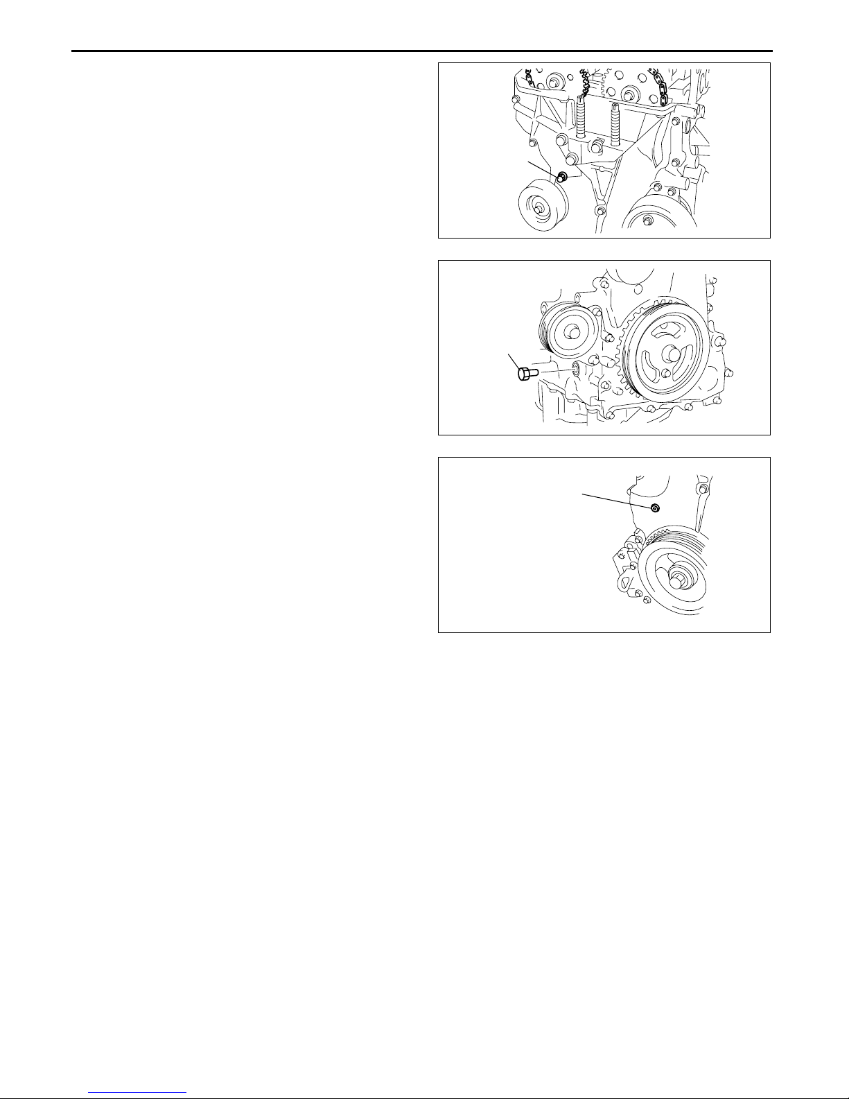
25. Install the new engine front cover upper blind
plug.
Tightening torque
8.0—11.5 N·m {82—117 kgf·cm, 71—101
in·lbf}
26. Install the cylinder block lower blind plug.
Tightening torque
18—22 N·m {1.9—2.2 kgf·m, 13.3—16.2 ft·lbf}
BLIND
PLUG
B3E0110E101
BLIND
PLUG
27. Install the new engine front cover lower blind plug.
Tightening torque
10—14 N·m {102—142 kgf·cm, 89—123
in·lbf}
End Of Sie
B3E0110E102
ENGINE FRONT
COVER LOWER
BLIND PLUG
B3E0110W063
01–10–26
Page 41
MECHANICAL
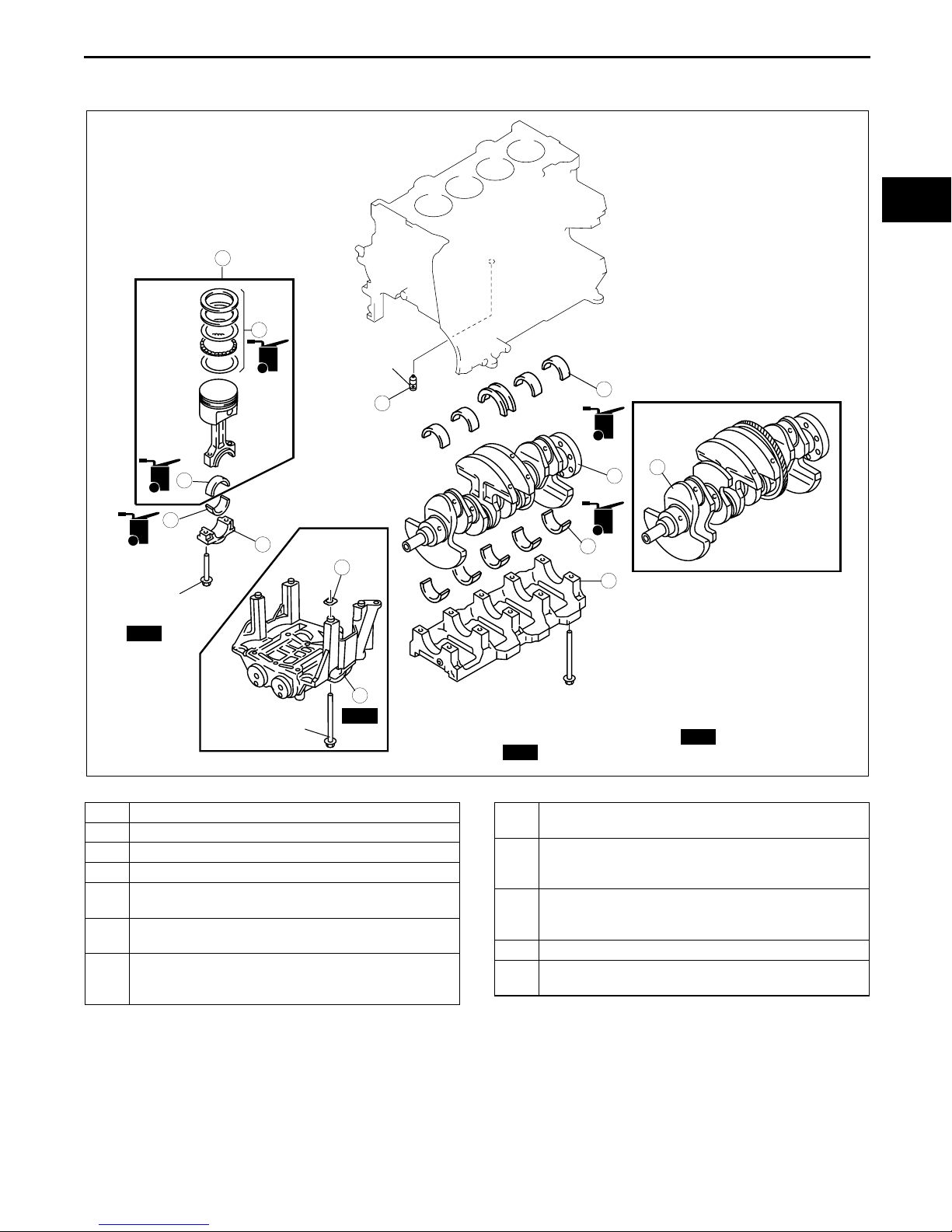
CYLINDER BLOCK (I) ASSEMBLY
1. Assemble in the order indicated in the table.
8
6
OIL
2.9—4.9 N·m
{30—40 kgf·cm,
25.67—43.4 in·lbf}
1
OIL
7
9
OIL
L3
10
11
26—32 {2.7—3.2,
19.2—23.6}+80
°—100°
SST
12
25+44—46
{2.6+4.5—4.7,
18.4+32.5—33.9}
SST
.
PLASTIC REGION TIGHTENING
BOLT
(BOLT STEM LENGTH 110 mm)
44—46 {4.5—4.6, 32.5—33.9}
°—185°
+175
SST
E5U011002000E08
2
L3
OIL
3
3
OIL
4
5
ELASTIC REGION TIGHTENING BOLT
(BOLT STEM LENGTH 104 mm)
3—7 N·m {30.6—71.3 kgf·cm,26.6—61.9 in·lbf}
+23—27 {2.4—2.7, 17—19.9}
+38—42 {3.9—4.2, 28.1—30.9}
Loosen all the bolts
+3—7 N·m {30.6—71.3 kgf·cm,26.6—61.9 in·lbf}
+18—22 {1.9—2.2, 13.3—16.2}
°—92.5°
+87.5
SST
N·m {kgf·m, ft·lbf}
01–10
E5U110ZE7S03
1 Oil jet valve
2 Upper main bearing, thrust bearing
3Crankshaft
4 Lower main bearing, thrust bearing
5 Main bearing cap
(See 01–10–28 Main Bearing Cap Assembly Note)
Piston ring
6
(See 01–10–28 Piston Ring Assembly Note)
7 Upper connecting rod bearing
(See 01–10–29 Connecting Rod Bearing Assembly
Note)
8 Connecting rod, piston assembly
(See 01–10–28 Piston Assembly Note)
9 Lower connecting rod bearing
(See 01–10–29 Connecting Rod Bearing Assembly
Note)
10 Connecting rod cap
(See 01–10–29 Connecting Rod Cap Assembly
Note)
11 Adjustment shim
12 Balancer unit
(See 01–10–29 Balancer Unit Assembly Note)
01–10–27
Page 42
MECHANICAL
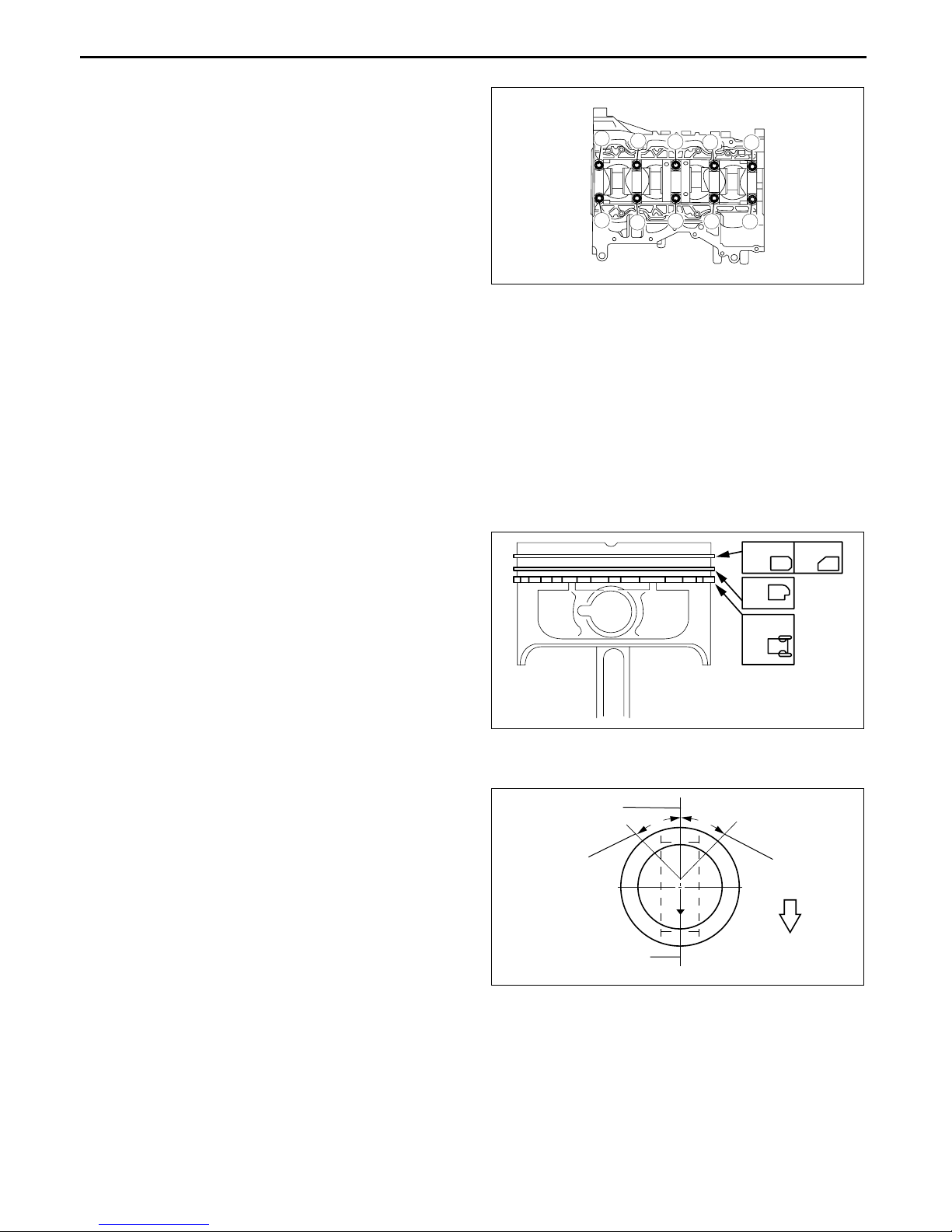
Main Bearing Cap Assembly Note
1. Install the main bearing caps in the order
indicated in the figure.
2. Tighten the main bearing cap bolts using the SST
(49 D032 316).
Tightening torque
Plastic region tightening bolt (Bolt stem
length 110 mm)
(1) 44—46 N·m {4.5—4.6 kgf·m, 32.5—33.9
ft·lbf}
(2) 175°—185°
Elastic region tightening bolt (Bolt stem
length 104 mm)
(1) Apply engine oil to all bolts.
(2) 3—7 N·m {30.6—71.3 kgf·cm, 26.6—61.9 in·lbf}
(3) 23—27 N·m {2.4—2.7 kgf·m, 17—19.9 ft·lbt}
(4) 38—42 N·m {3.9—4.2 kgf·m, 28.1—30.9 ft·lbt}
(5) Loosen all the bolts. (no remaining torque.)
(6) 3—7 N·m {30.6—71.3 kgf·cm, 26.6—61.9 in·lbt}
(7) 18—22 N·m {1.9—2.2 kgf·m, 13.3—16.2 ft·lbt}
(8) 87.5°—92.5°
Piston Ring Assembly Note
1. Install the two oil control ring segments and spacer.
2. Verify that the second ring is installed with scraper face side downward.
3. Verify that the top ring is installed with scraper
face side inner of upper.
10
9
5
1
3
7
2
4
LF
8
B3E0110E105
L3
6
Piston Assembly Note
1. Position the end gap of each ring as indicated in
the figure.
TOP RING
UPPER OIL
RING RAIL
OIL RING SPACER
AND SECOND RING
30°
C3U0110E056
30°
LOWER OIL
RING RAIL
B3E0110E107
01–10–28
Page 43
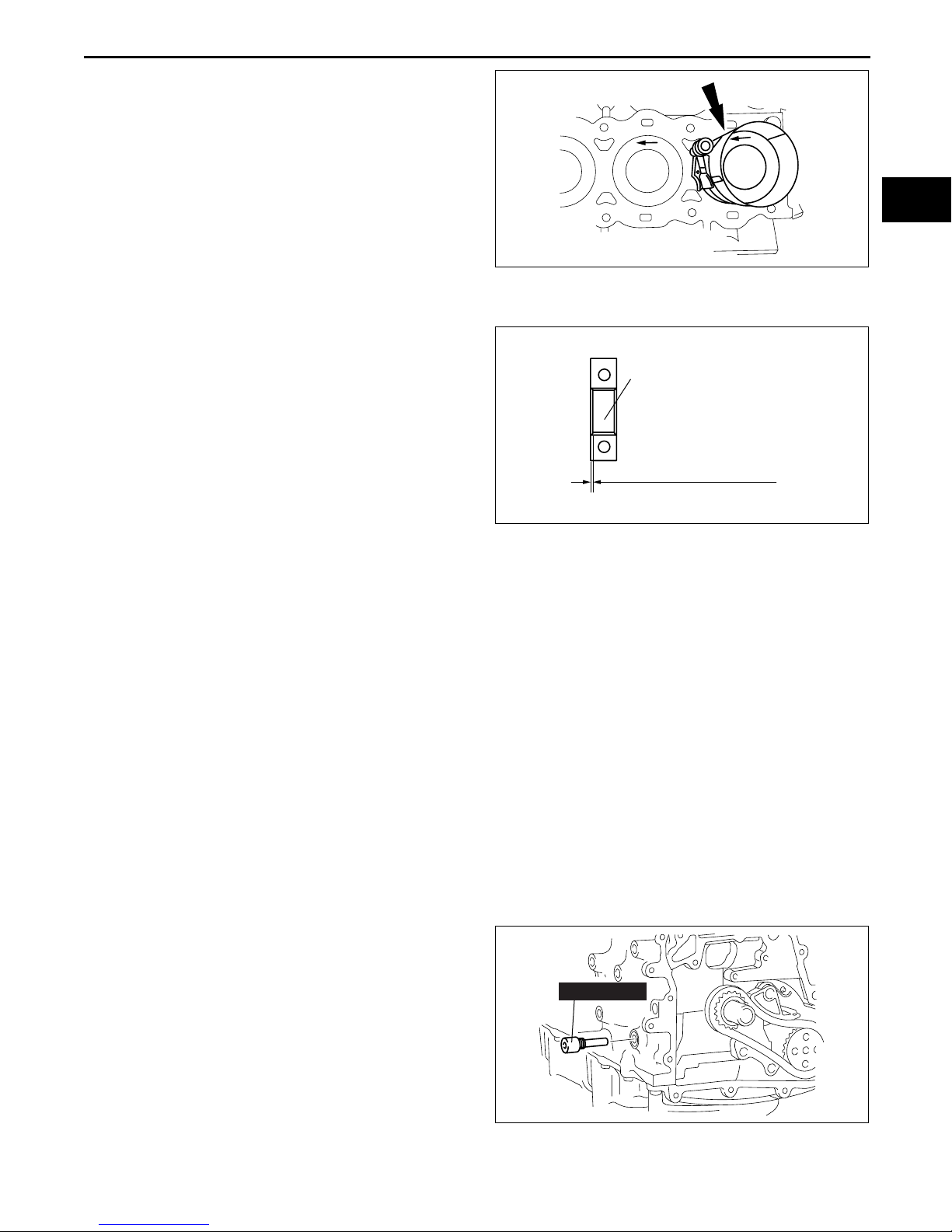
2. Insert the piston and connecting rod into the
cylinder with the arrow mark to front of the engine.
Connecting Rod Bearing Assembly Note
1. Install the connecting rod bearing to the
connecting rod and connecting rod caps, as
shown in the figure.
MECHANICAL
CONNECTING ROD
BEARING
2.3
—2.7 mm {0.091—0.106 in}
01–10
B3E0110E108
B3E0110E109
Connecting Rod Cap Assembly Note
Caution
• When assembling the connecting rod caps, align the broken, rough faces of the connecting rods
and connecting rod caps.
1. Tighten the connecting rod bolts in two steps using the SST (49 D032 316).
Tightening torque
(1) 26—32 N·m
{2.7—3.2 kgf·m, 19.2—23.6 ft·lbf}
(2) 80°—100°
Balancer Unit Assembly Note
1. Confirm by visual inspection that there is no damage to the balancer unit gear and verify that the shaft turns
smoothly.
• If there is any damage or malfunction, replace the balancer unit.
Caution
• Due to the precision interior construction of the balancer unit, it cannot be disassembled.
2. Install the SST as shown in the figure.
3. Turn the crankshaft clockwise the crankshaft is in
the No.1 cylinder TDC position (until the balance
weight is attached to the SST).
4. Install the adjustment shim to the seat face of the
303-507
balancer unit.
D3U110ZE4007
01–10–29
Page 44
MECHANICAL
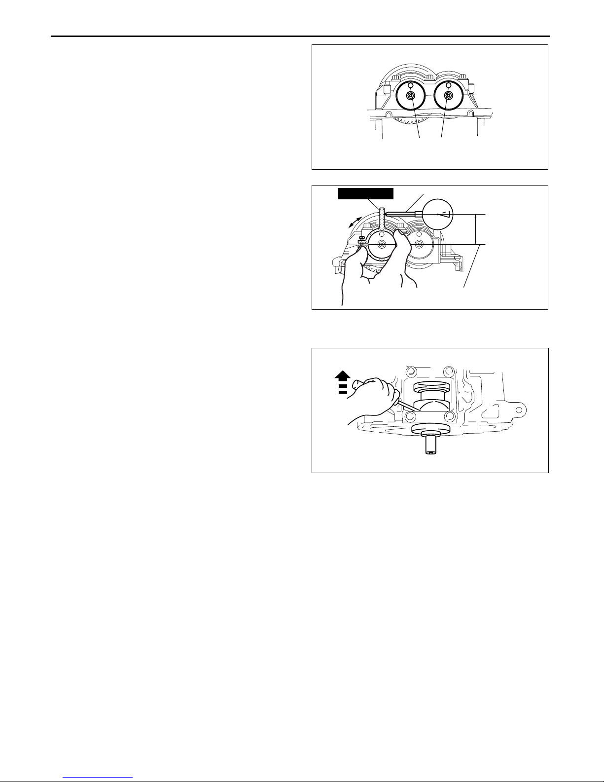
5. With the balancer unit marks at the exact top
center, assemble the unit to the cylinder block.
6. Set the SST as shown, then measure the gear
backlash using a dial gauge.
49 G011 201
MARK
B3E0110E111
DIAL GAUGE
41.4 mm
{1.629 in}
DRIVEN GEAR SHAFT CENTER
B3E0110E112
Note
• For an accurate measurement of gear
backlash, insert a screwdriver into the
crankshaft No. 1 balance weight area and
set both the rotation and the thrust direction
with the screwdriver, using a prying action,
as shown in the figure.
B3E0110E113
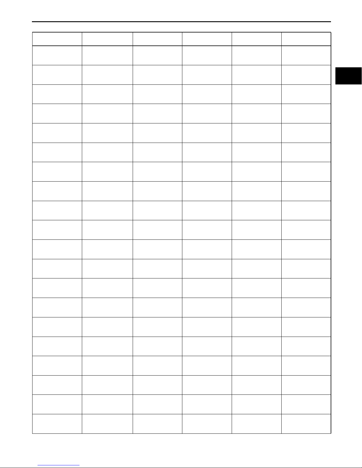
• If the backlash exceeds the specified range, remeasure the backlash and, using the adjustment shim
selection table, select the proper shim, according to the following procedure.
Caution
• When measuring the backlash, rotate the crankshaft one full rotation and verify that it is within the
specified range at all of the following six positions: 10°, 30°, 100°, 190°, 210°, 280° ATDC.
Val ue range
0.005—0.101 mm {0.00019—0.0039 in}
(1) Using master adjustment shim (No.50), assemble the balancer unit to the cylinder block, then measure the
backlash.
(2) Select the proper adjustment shim according to the measured value.
(3) Install the selected adjustment shim to the balancer unit, then assemble the balancer unit to the cylinder
block.
01–10–30
Page 45
Adjustment shim selection table
Backlash
mm {in}
0.267—0.273
{0.01051—
0.01074}
0.260—0.266
{0.01023—
0.01047}
0.253—0.259
{0.00996—
0.01019}
0.246—0.252
{0.00968—
0.00992}
0.239—0.245
{0.00940—
0.00964}
0.232—0.238
{0.00913—
0.00937}
0.225—0.231
{0.00885—
0.00909}
0.218—0.224
{0.00858—
0.00881}
0.211—0.217
{0.00830—
0.00854}
0.204—0.210
{0.00803—
0.00826}
0.197—0.203
{0.00775—
0.00799}
0.190—0.196
{0.00748—
0.00771}
0.183—0.189
{0.00720—
0.00744}
0.176—0.182
{0.00692—
0.00716}
0.169—0.175
{0.00665—
0.00688}
0.162—0.168
{0.00637—
0.00661}
0.155—0.161
{0.00610—
0.00633}
0.148—0.154
{0.00582—
0.00606}
0.141—0.147
{0.00555—
0.00578}
0.134—0.140
{0.00527—
0.00551}
Selection shim
(No.)
15 1.15 {0.0452}
16 1.16 {0.0456}
17 1.17 {0.0460}
18 1.18 {0.0464}
19 1.19 {0.0468}
20 1.20 {0.0472}
21 1.21 {0.0476}
22 1.22 {0.0480}
23 1.23 {0.0484}
24 1.24 {0.0488}
25 1.25 {0.492}
26 1.26 {0.496}
27 1.27 {0.499}
28 1.28 {0.503}
29 1.29 {0.507}
30 1.30 {0.511}
31 1.31 {0.515}
32 1.32 {0.519}
33 1.33 {0.523}
34 1.34 {0.527}
MECHANICAL
Shim thickness
mm {in}
Backlash
mm {in}
0.127—0.133
{0.00500—
0.00523}
0.120—0.126
{0.00472—
0.00496}
0.113—0.119
{0.00444—
0.00468}
0.106—0.112
{0.00417—
0.00440}
0.099—0.105
{0.00389—
0.00413}
0.092—0.098
.087 {0.00362—
0.00385}
0.085—0.091
{0.00334—
0.00358}
0.078—0.084
{0.00307—
0.00330}
0.071—0.077
{0.00279—
0.00303}
0.064—0.070
{0.00251—
0.00275}
0.057—0.063
{0.00224—
0.00248}
0.050—0.056
{0.00196—
0.00220}
0.043—0.049
{0.00169—
0.00192}
0.036—0.042
{0.00141—
0.00165}
0.029—0.035
{0.00114—
0.00137}
0.022—0.028
{0.000866—
0.00110}
0.015—0.021
{0.00059—
0.000826}
0.008—0.014
{0.000314—
0.000551}
0.001—0.007
{0.00003—
0.000275}
0.000—0.000
{0.000—0.000}
Selection shim
(No.)
35 1.35 {0.0531}
36 1.36 {0.0535}
37 1.37 {0.0539}
38 1.38{0.0543}
39 1.39 {0.0547}
40 1.40 {0.0551}
41 1.41 {0.0555}
42 1.42 {0.0559}
43 1.43 {0.0562}
44 1.44 {0.0566}
45 1.45 {0.0570}
46 1.46 {0.0574}
47 1.47 {0.0578}
48 1.48 {0.0582}
49 1.49 {0.0586}
50 (master) 1.50 {0.0590}
51 1.51 {0.0594}
52 1.52 {0.0598}
53 1.53 {0.0602}
54 1.54 {0.0606}
Shim thickness
mm {in}
01–10
End Of Sie
01–10–31
Page 46
MECHANICAL
SEALANT
OIL
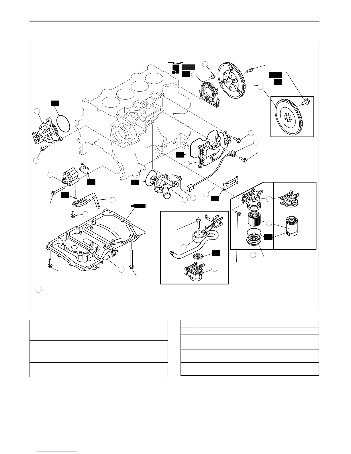
CYLINDER BLOCK (II) ASSEMBLY
1. Assemble in the order indicated in the table.
R
4
A
2
R
8.0—12 N·m
{81.6—122.3 kgf·cm,
70.9—106.2in·lbf}
+20
°—25°
17—23
{1.8—2.3,
12.6—16.9}
:
A
8.0—11.5 N·m
{81.6—117.2 kgf·cm,
70.9—101.7 in·lbf}
R
IF EQUIPPED
3
A
R
SEALANT
12
17—23
{1.8—2.3,
12.6—16.9}
E5U011002000E09
46—54 {4.70—5.50,
34.0—39.8}+76—84
OIL
SST
R
A
1
{7.75—8.56,
56.1—61.9}+108—116
{11.1—11.8, 79.7—85.5}
SST
R
13
MTX
A
7
16.2—23.8 {1.66—2.42,
R
6
B
A
5
WITH OIL COOLER
R
12.0—17.5}
WITHOUT OIL COOLER
CARTRIDGE
TYPE
8
SPIN-ON
TYPE
10
30—39
{3.1—3.9,
22.2—28.7}
R
9
R
8
20—30
{2.1—3.0,
14.8—22.1}
11
30—35
{3.1—3.5,
22.2—25.8}
15—20
{1.6—2.0,
11—14}
N·m {kgf·m, ft·lbf}
.
1 Rear oil seal
(See 01–10–33 Rear Oil Seal Assembly Note)
2 Oil pump
3 Oil strainer
4 Water pump
5 Thermostat
6 Oil separator
7 Knock sensor
01–10–32
E5U110ZE7S08
8 Oil filter adapter
9 Oil cooler
10 Oil filter
11 Oil filter cover (cartridge type)
12 Oil pan
(See 01–10–34 Oil pan Assembly Note)
13 Flywheel (MTX), Drive plate (ATX) (See 01–10–33
Drive Plate (ATX), Flywheel (MTX) Assembly Note)
Page 47
MECHANICAL
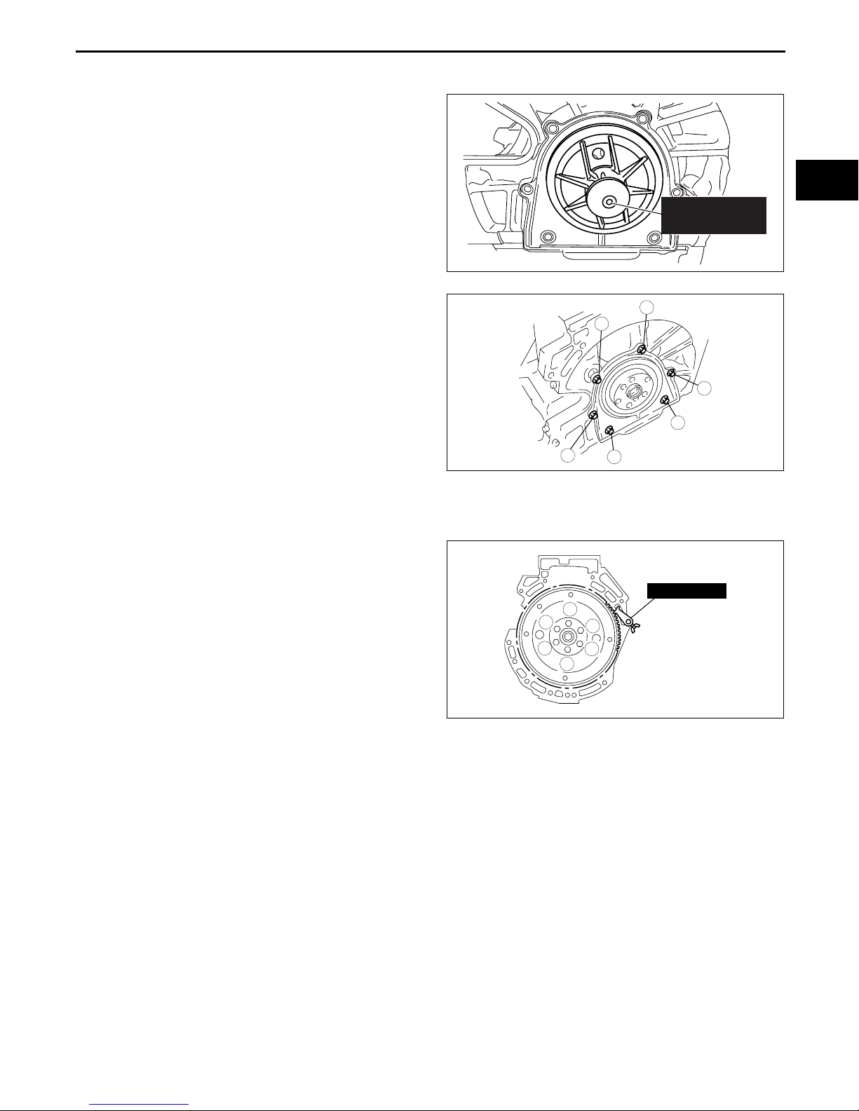
Rear Oil Seal Assembly Note
1. Apply clean engine oil to the new oil seal lip.
2. Install the rear oil seal using the SST as shown in
the figure.
3. Tighten the rear oil seal bolts in the order as
shown in the figure.
Tightening torque
8.0—11.5 N·m
{81.6—117.2 kgf·cm, 70.9—101.7 in·lbf}
01–10
303-328
(49 UN30 3328)
CUE110BW2005
3
5
1
6
Drive Plate (ATX), Flywheel (MTX) Assembly Note
1. Hold the crankshaft using the SST.
2. Tighten the bolts in the 3 steps in the figure.
Tightening torque
(1) 46—54 N·m
{4.70—5.50 kgf·m, 34.0—39.8 ft·lbf
(2) 76—84 N·m
{7.75—8.56 kgf·m, 56.1—61.9 ft·lbf
(3) 108—116 N·m
{11.1—11.8 kgf·m, 79.7—85.5 ft·lbf
2
4
B3E0110E116
49 E011 1A0
1
3
5
6
4
2
B3E0110E119
01–10–33
Page 48
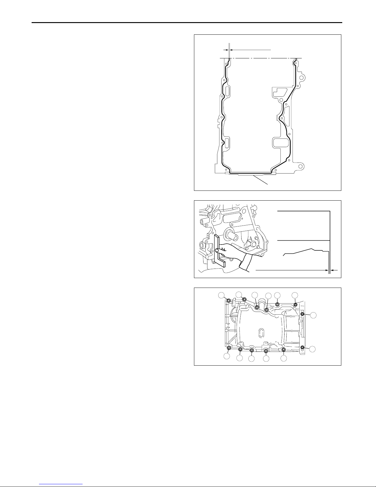
MECHANICAL
Oil pan Assembly Note
1. Apply a continuous bead of silicone sealant to the
oil pan as indicated in the figure.
Caution
• Install the oil pan within 10min of
applying the silicone sealant
• Make sure that there is no oil or dust on
the seal side of oil pan.
2. Use a square ruler to unite the oil pan and the
cylinder block junction side on the engine front
cover side.
ENGINE FRONT SIDE
—3.2
2.2
mm{0.087
REAR OIL SEAL
—0.126
in}
C3U0110E061
CYLINDER
BLOCK
3. Tighten the rear oil pan bolts in the order as
shown in the figure.
Tightening torque
17—23 N·m
{1.8—2.3 kgf·m, 12.6—16.9 ft·lbf}
End Of Sie
13
12
-0.05—0.05 mm {-0.0020—0.0020 in}
8
4
7
3
5
1
6
2
OIL PAN
B3E0110E120
9
10
11
B3E0110E122
01–10–34
Page 49
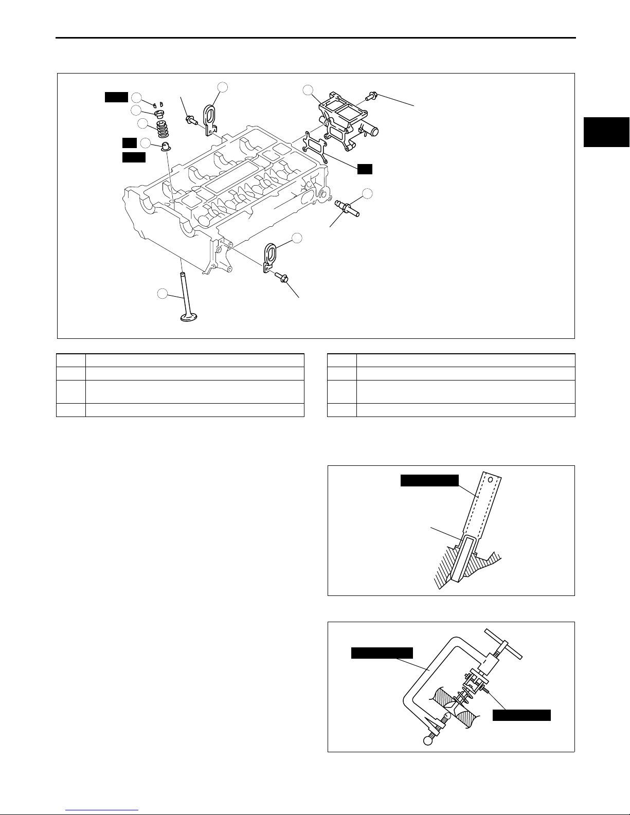
Engine Workshop Manual LF L3 (1866–1U–05H)
MECHANICAL
CYLINDER HEAD (I) ASSEMBLY
1. Assemble in the order indicated in the table..
SST
42—48 {4.3—4.8,
31.0—35.4}
7
8
6
5
R
3
SST
4
1
R
2
56—60 {5.8—6.1,
8
41.3—44.2}
42—48 {4.3—4.8, 31.0—35.4}
E5U011002000E10
8.0—11.5 N·m {81.6—117.2
kgf·cm, 70.9—101.7 in·lbf}
01–10
N·m {kgf·m, ft·lbf}
B3E0110E130
1 Water outlet
2 EGR pipe
3 Valve seal
(See 01–10–35 Valve Seal Assembly Note)
4Valve
Valve Seal Assembly Note
1. Press the valve seal onto the valve guide by hand.
2. Lightly tap the SST using a plastic hammer.
Valve Keeper Assembly Note
1. Install the valve keeper using the SSTs.
End Of Sie
5Valve spring
6 Upper valve spring seat
7 Valve keeper
(See 01–10–35 Valve Keeper Assembly Note)
8 Engine hanger
49 T032 302
VALVE
SEAL
B3E0110E123
49 0636 100B
49 B012 0A2
B3E0110E124
01–10–35
Page 50
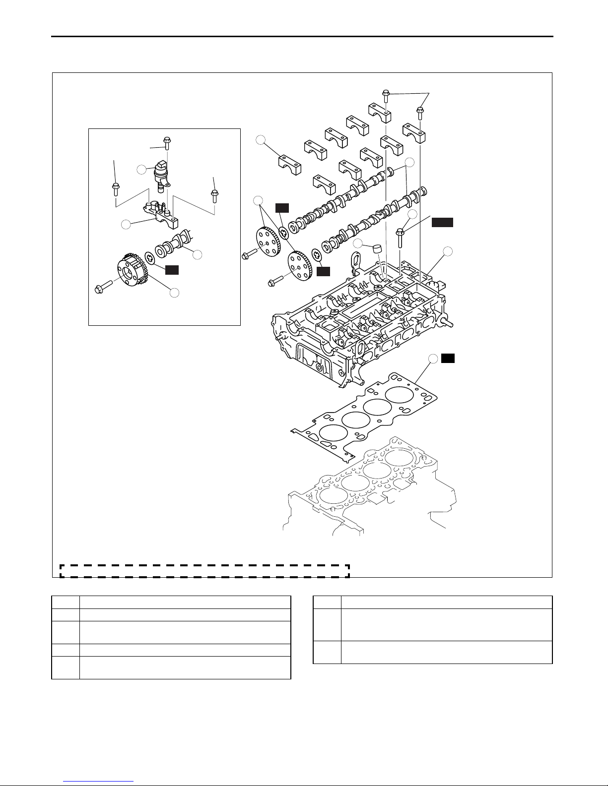
Engine Workshop Manual LF L3 (1866–1U–05H)
MECHANICAL
CYLINDER HEAD (II) ASSEMBLY
1. Assemble in the order indicated in the table.
WITH VARIABLE VALVE TIMING MECHANISM
8.0—11.5 N·m
{81.5—117 kgf·cm
70.8—101in·lbf}
8
5.0—9.0 N·m
{51.0—91.7 kgf·cm,
44.3—79.5 in·lbf}+
14—17
{1.43—1.73,
10.4—12.5}
6
5
*
R
7
E5U011002000E11
5.0—9.0 N·m
{51.0—91.7 kgf·cm,
44.3—79.5 in·lbf}+
14—17
{1.43—1.73,
10.4—12.5}
6
5
3—11
{30.6—112 kgf·cm,
26.6—97.3 in·lbf}+
13—17 {1.4—1.7, 9.6—12.5}+
7
*
R
43—47 {4.4—4.7, 31.8—34.6}+
88°—92°+
88°—92°
3
SST
4
2
*
R
*: IF WASHER IS NOT INSTALLED TO THE ENGINE, INSTALL A NEW WASHER.
.
1 Cylinder head gasket
2 Cylinder head
3 Cylinder head bolt
(See 01–10–37 Cylinder Head Bolt Assembly Note)
4 Tappet
5 Camshaft
(See 01–10–37 Camshaft Assembly Note)
R
1
N·m {kgf·m, ft·lbf}
E5U110ZECL02
6 Camshaft cap
7 Camshaft sprocket, variable valve timing actuator
(See 01–10–37 Camshaft Sprocket, Variable Valve
Timing Actuator Assembly Note)
8 Oil control valve (OCV) (With variable valve timing
mechanism)
01–10–36
Revised 12/2005 (Ref. No. R145/05)
Page 51
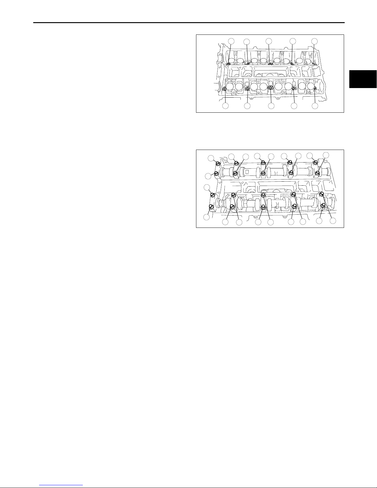
MECHANICAL
Cylinder Head Bolt Assembly Note
1. Tighten the cylinder head bolts in the order
8
indicated in the figure in 5 steps using the SST
4
(49 D032 316).
Tightening torque
(1) 3—11 N·m
{30.6—112 kgf·cm, 26.6—97.3 in·lbf}
(2) 13—17 N·m
{1.4—1.7 kgf·m, 9.6—12.5 ft·lbf}
(3) 43—47 N·m
{4.4—4.7 kgf·m, 31.8—34.6 ft·lbf}
(4) 88°—92°
7
3
(5) 88°—92°
Camshaft Assembly Note
1. Set the cam position of No.1 cylinder at the top dead center (TDC) and install the camshaft.
2. Temporarily tighten the camshaft bearing caps evenly in 2—3 steps.
3. Tighten the camshaft cap bolt in the order shown
5
two steps.
9
6
1
2
1
2
5
9
01–10
6
3
10
C3U0110E054
8
7
4
Tightening torque
(1) 5.0—9.0 N·m
{51.0—91.7 kgf·cm, 44.3—79.5 in·lbf}
(2) 14—17 N·m
10
20
{1.43—1.73 kgf·m, 10.4—12.5 ft·lbf}
19
15
16
11
12
13
14
17
B3E0110E098
Camshaft Sprocket, Variable Valve Timing Actuator Assembly Note
1. Temporarily tighten the camshaft sprocket or variable valve timing actuator installation bolts by hand until the
timing chain is installed.
2. Fully tighten the camshaft sprocket or variable valve timing actuator installation bolts after timing chain
installation.
End Of Sie
18
01–10–37
Page 52
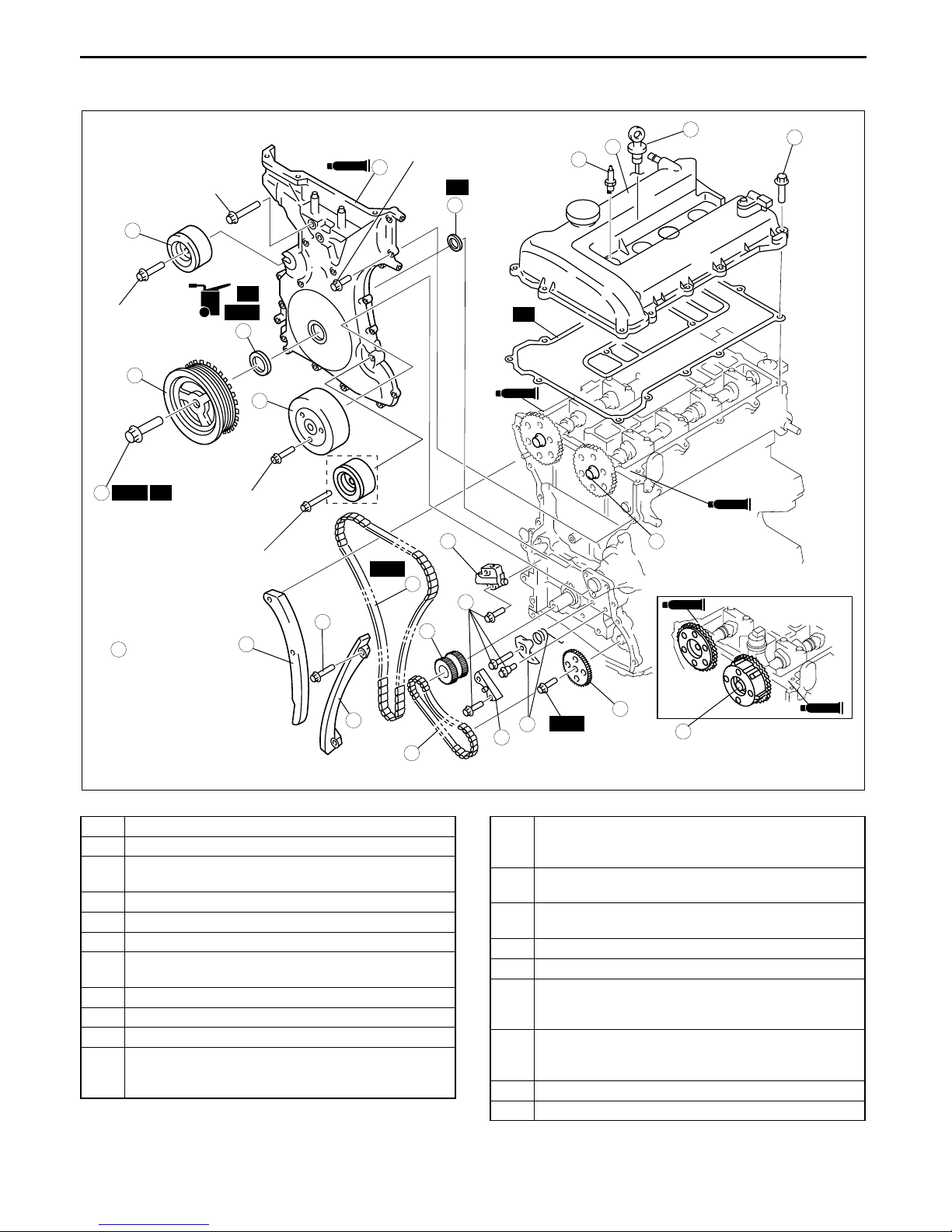
MECHANICAL
TIMING CHAIN ASSEMBLY
1. Assemble in the order indicated in the table.
40—55
{4.1—5.6,
29.6—40.5}
SEALANT
12
14
R
20—30
{2.1—3.0,
14.8—22.1}
OIL
SST
13
16
15
WITHOUT
SST
17
96—104
{9.8—10.6,
70.9—76.7}+
87°—93°
R
20—30
{2.1—3.0,
14.8—22.1}
40—55
{4.1—5.6,
29.6—40.5}
A/C
SST
A
8.0—10.5 N·m
:
A
{81.6—107.1 kgf·cm,
70.9—92.9 in·lbf}
9
.
8.0—11.5 N·m
{81.6—117.2 kgf·cm,
70.9—101.7 in·lbf}
R
6
10
7
A
1
R
SEALANT
19
20
18
11
69—75 {7.1—7.6, 50.9—55.3}
WITH VARIABLE VALVE TIMING
MECHANISM
SEALANT
E5U011002000E12
A
SEALANT
8
2
1 Crankshaft sprocket
2 Oil pump chain
3 Oil pump sprocket
(See 01–10–39 Oil Pump Sprocket Assembly Note.)
4 Oil pump chain guide
5 Oil pump chain tensioner
6 Seal (With variable valve timing mechanism)
7 Timing chain
(See 01–10–39 Timing Chain Assembly Note.)
8 Chain guide
9 Tensioner arm
10 Chain tensioner
11 Camshaft sprocket, variable valve timing actuator
(See 01–10–40 Camshaft Sprocket, Variable Valve
Timing Actuator Assembly Note.)
5
4
20—30
{2.1—3.0,
14.8—22.1}
11
69—75 {7.1—7.6, 50.9—55.3}
N·m {kgf·m, ft·lbf}
SST
3
SEALANT
E5U110ZE7S05
12 Engine front cover
(See 01–10–41 Engine Front Cover Assembly
Note.)
13 Front oil seal
(See 01–10–40 Front Oil Seal Assembly Note.)
14 Drive belt idler pulley (Without stretch-type A/C drive
belt)
15 Water pump pulley
16 Crankshaft pulley
17 Crankshaft pulley lock bolt
(See 01–10–41 Crankshaft Pulley Lock Bolt
Assembly Note.)
18 Cylinder head cover
(See 01–10–42 Cylinder Head Cover Assembly
Note)
19 Spark plug
20 Dipstick (if equipped)
01–10–38
Page 53
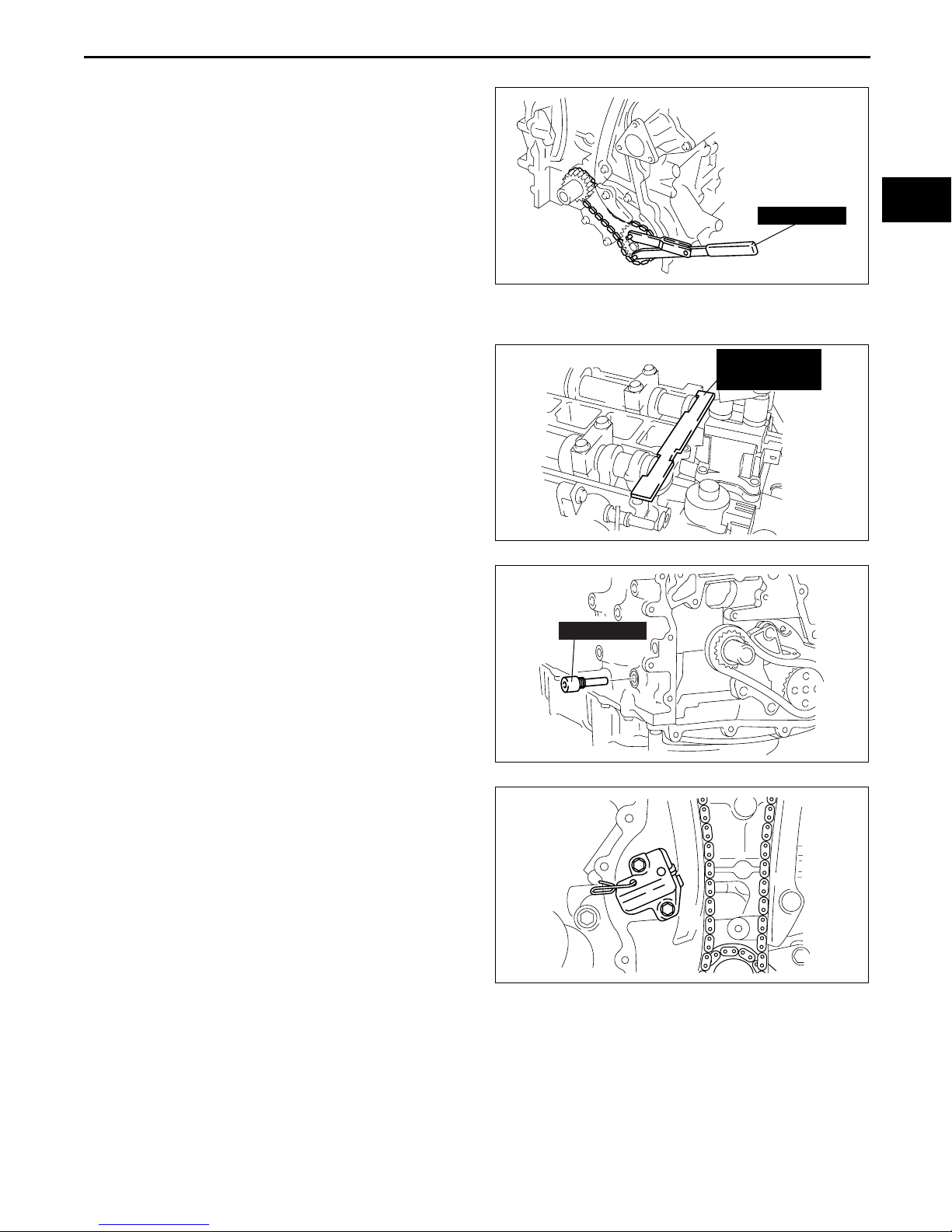
MECHANICAL
Oil Pump Sprocket Assembly Note
1. Hold the oil pump sprocket using the SST.
Timing Chain Assembly Note
1. Install the SST to the camshaft, then align the No.
1 camshaft position with the TDC.
2. Remove the cylinder block lower blind plug.
01–10
49 G032 354
B3E0110E125
303-465
(49 UN30 3465)
3. Install the SST as shown in the figure.
4. Turn the crankshaft clockwise so that the
crankshaft is in the No.1 cylinder TDC position.
5. Install the timing chain.
6. Install the chain tensioner and remove the
retaining wire.
C3U0110E052
303-507
D3U110ZE4007
B3E0110E126
01–10–39
Page 54
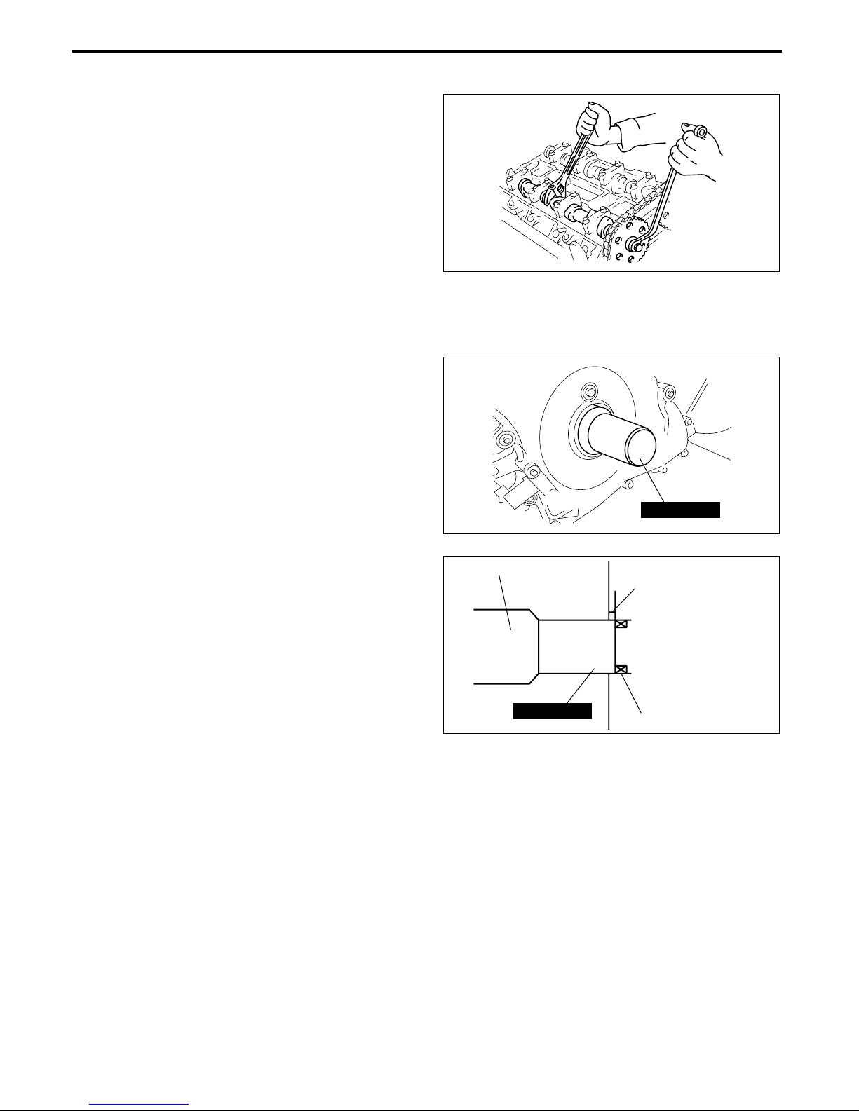
MECHANICAL
Camshaft Sprocket, Variable Valve Timing Actuator Assembly Note
1. Hold the camshaft using a suitable wrench on the cast hexagon as shown in the figure.
2. Tighten the camshaft sprocket lock bolt.
Tightening torque
69—75 N·m {7.1—7.6 kgf·m, 50.9—55.3
ft·lbf}
Front Oil Seal Assembly Note
1. Apply clean engine oil to the oil seal.
2. Push the oil seal slightly in by hand.
3. Compress the oil seal using the SST and a
hammer.
B3E0110E095
HAMMER
49 H010 401
49 H010 401
B3E0110E127
ENGINE FRONT COVER
0—0.5 mm
{0—0.019 in}
FRONT OIL SEAL
E5U110ZE7S09
01–10–40
Page 55
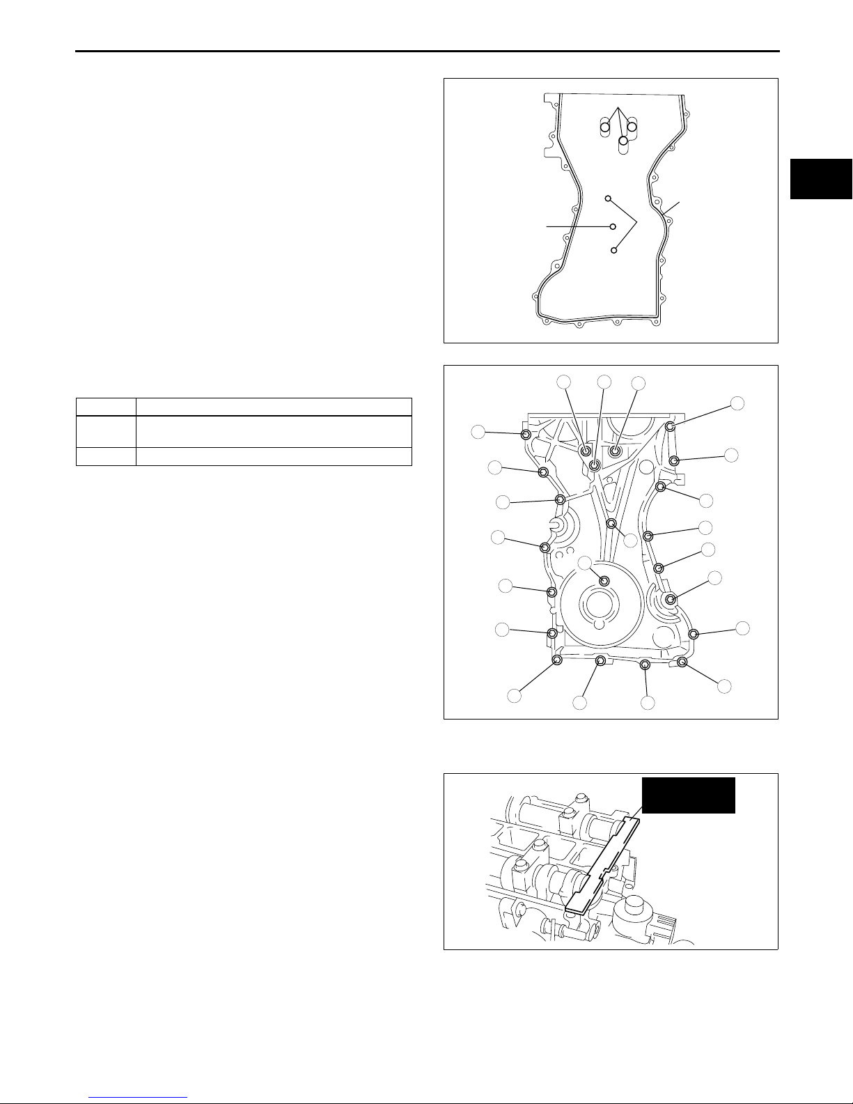
MECHANICAL
Engine Front Cover Assembly Note
1. Apply silicone sealant to the engine front cover as
shown in the figure.
Caution
• Install the cylinder head cover within 10
min of applying the silicone sealant.
• Silicone sealant is not need in area C as
indicated below due to an existing. (With
variable valve timing mechanism)
• Make sure that there is no oil or dust on
the seal side of oil pan.
Thickness
A: 2.2—3.2 mm {0.087—0.125 in}
B: 1.5—2.5 mm {0.059—0.098 in}
2. Install the cylinder head cover bolts in the order
as shown in the figure.
Bolt No. Tightening torque N·m {kgf·m, ft·lbf}
1—18 8.0—11.5 N·m
{81.6—117.2 kgf·cm, 70.9—101.7 in·lbf}
19—22 40—55 {4.1—5.6, 29.6—40.5}
17
10
B
01–10
A
21
B
B3E0110E129
22
C
20
18
11
Crankshaft Pulley Lock Bolt Assembly Note
1. Install the SST to the camshaft as shown in the
figure.
7
3
1
8
4
5
2
6
9
16
15
14
303-465
(49 UN30 3465)
19
12
13
B3E0110E062
C3U0110E066
01–10–41
Page 56
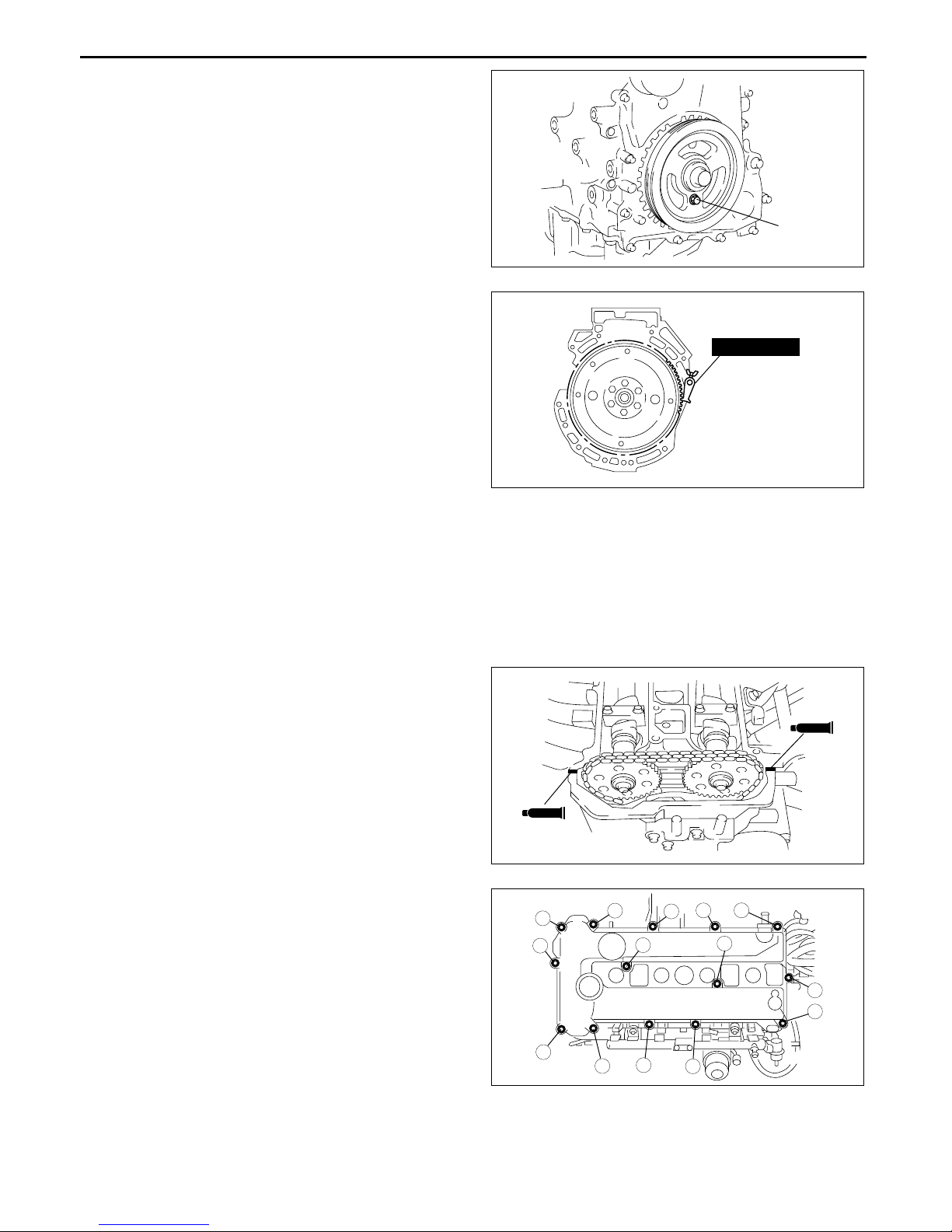
MECHANICAL
2. Install the M6 × 1.0 bolt in by hand.
3. Turn the crankshaft clockwise so that the
crankshaft is in the No.1 cylinder TDC position.
4. Hold the crankshaft pulley using the SST.
5. Tighten the crankshaft pulley lock bolt in the order
shown following two steps using the SST (49
D032 316).
Tightening torque
(1) 96—104 N·m
{9.8—10.6 kgf·m, 70.9—76.7 ft·lbf}
(2) 87°—93°
6. Remove the M6 × 1.0 bolt.
7. Remove the SST from the camshaft.
8. Remove the SST from the block lower blind plug.
9. Rotate the crankshaft clockwise two turns until
the TDC position.
• If not aligned, loosen the crankshaft pulley lock bolt and repeat from Step 1.
10. Install the cylinder block lower blind plug.
BOLT
B3E0110E063
49 E011 1A0
E5U110ZE7S11
Tightening torque
18—22 N·m {1.9—2.2 kgf·m, 13.3—16.2 ft·lbf}
Cylinder Head Cover Assembly Note
1. Apply silicone sealant to the mating faces as
shown in the figure.
Caution
• Install the cylinder head cover within 10
min of applying the silicone sealant.
Dot diameter
4.0—6.0 mm {0.16—0.23 in}
2. Install the cylinder head cover with a new gasket.
3. Tighten the bolts in the order shown in the figure.
Tightening torque
8.0 —10.5 N·m
{81.6—107.1 kgf·cm, 70.9—92.9 in·lbf}
End Of Sie
SEALANT
11
10
9
SEALANT
B3E0110E064
6
2
7
3
12
1
13
14
4
5
8
B3E0110W050
01–10–42
Page 57
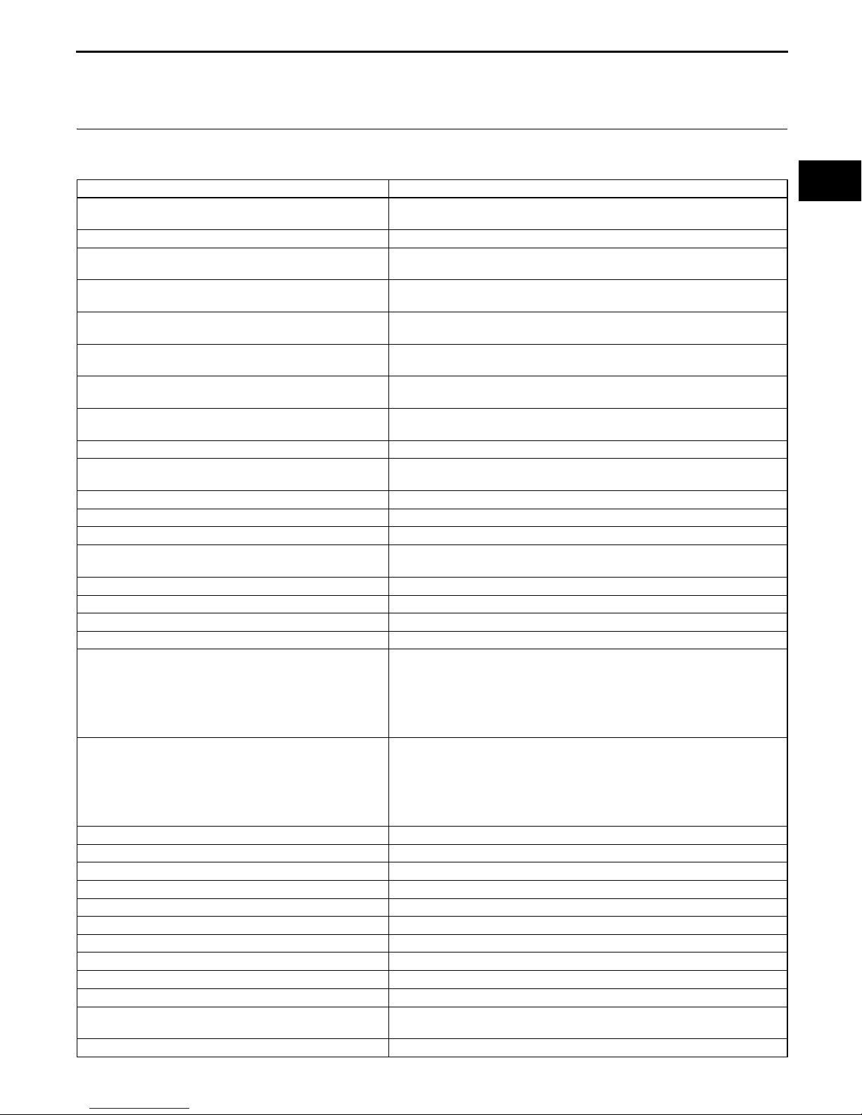
TECHNICAL DATA
01–50 TECHNICAL DATA
ENGINE TECHNICAL DATA . . . . . . . . . . 01–50–1
End of Toc
ENGINE TECHNICAL DATA
Item Specification
Cylinder head gasket contact surface distortion
(Maximum)
Manifold contact surfaces distortion (Maximum) 0.10 mm {0.004 in}
Manifold contact surfaces distortion (Maximum
grinding)
Valve head margin thickness (Minimum)
Valve length (Standard)
Valve length (Minimum)
Valve stem diameter (Standard)
Valve stem diameter (Minimum)
Valve guide inner diameter (Standard) 5.509—5.539 mm {0.2169—0.2180 in}
Valve stem to guide clearance (Standard)
Valve stem to guide clearance (Maximum) 0.10 mm {0.004 in}
Valve guide protrusion height (standard) 12.2—12.8 mm {0.481—0.503 in}
Valve seat contact width (Standard) 1.2—1.6 mm {0.048—0.062 in}
Valve protrusion height (Standard)
Valve spring pressing force 390 N {39.76 kgf, 87.67 lbf}
Valve spring standard height H 28.68 mm {1.129 in}
Valve spring out-of-square (Maximum) 1.95 mm {0.0767 in}
Maximum runout (Maximum) 0.03 mm {0.0012 in}
Camshaft standard height (mm {in})
Camshaft minimum height (mm {in})
Camshaft journal diameter (Standard) 24.96—24.98 mm {0.9827—0.9834 in}
Camshaft journal diameter (Minimum) 24.95 mm {0.982 in}
Camshaft journal oil clearance (Standard) 0.035—0.080 mm {0.0014—0.0031 in}
Camshaft journal oil clearance (Maximum) 0.09 mm {0.0035 in}
Camshaft end play (Standard) 0.09—0.24 mm {0.0035—0.0094 in}
Camshaft end play (Maximum) 0.25 mm {0.0098 in}
Tappet bore diameter (Standard) 31.000—31.030 mm {1.2205—1.2216 in}
Tappet diameter (Standard) 30.970—30.980 mm {1.2193—1.2196 in}
Tappet-to-Tappet bore oil clearance (Standard) 0.02—0.06 mm {0.0008—0.0023 in}
Tappet-to-Tappet bore oil clearance (Maximum) 0.15 mm {0.006 in}
Cylinder head gasket contact surfaces distortion
(Maximum)
Cylinder bore diameter (Standard) 87.500—87.530 mm {3.4449—3.4460 in}
IN: 102.99—103.79 mm {4.055—4.086 in}
EX: 104.25—105.05 mm {4.105—4.135 in}
IN: 5.470—5.485 mm {0.2154—0.2159 in}
EX: 5.465—5.480 mm {0.2152—0.2157 in}
IN: 0.024—0.069 mm {0.0009—0.0027 in}
EX: 0.029—0.074 mm {0.0012—0.0029 in}
IN: 40.64—42.24 mm {1.600—1.662 in}
EX: 40.50—42.10 mm {1.595—1.657 in}
With variable valve timing mechanism
Without variable valve timing mechanism
With variable valve timing mechanism
Without variable valve timing mechanism
0.10 mm {0.004 in}
0.15 mm {0.006 in}
IN: 1.62 mm {0.0637 in}
EX: 1.82 mm {0.0716 in}
IN: 102.99 mm {4.055 in}
EX: 104.25 mm {4.104 in}
IN: 5.440 mm {0.2142 in}
EX: 5.435 mm {0.2140 in}
IN: 42.44 {1.671}
EX: 41.18 {1.621}
IN: 42.12 {1.659}
EX: 41.08 {1.618}
IN: 42.33 {1.666}
EX: 41.06 {1.616}
IN: 42.01 {1.653}
EX: 40.96 {1.612}
0.10 mm {0.004 in}
E5U015000000E01
01–50
01–50–1
Page 58
TECHNICAL DATA
Item Specification
Minimum / maximum bore diameter limit 87.440—87.590 mm {3.4425—3.4484 in}
Oil jet valve air pressure
Piston diameter (Standard) 87.465—87.495 mm {3.4435—3.4446 in}
Piston-to-cylinder clearance (Standard) 0.025—0.045 mm {0.0010—0.0017 in}
Piston-to-cylinder clearance (Maximum) 0.11 mm {0.0043 in}
Piston ring-to-ring groove clearance (Standard)
Piston ring-to-ring groove clearance (Maximum)
Piston end gap (Standard)
Piston end gap (Maximum) 1.0 mm {0.0393 in}
Crankshaft end play (Standard) 0.22—0.45 mm {0.0087—0.0177 in}
Crankshaft end play (Maximum) 0.55 mm {0.0216 in}
Crankshaft runout (Maximum) 0.05 mm {0.0019 in}
Main journal bearing size
Main journal out of round (Maximum) 0.05 mm {0.0019 in}
Crank pin journal diameter [LF]
Crank pin journal diameter [L3]
Crank pin out of round (Maximum) 0.05 mm {0.0019 in}
Main journal oil clearance (Standard) 0.019—0.035 mm {0.0007—0.0013 in}
Main journal oil clearance (Maximum) 0.10 mm {0.0039 in}
Main bearing size
Connecting rod side clearance (Standard) 0.14—0.36 mm {0.0056—0.0141 in}
Connecting rod side clearance (Maximum) 0.435 mm {0.0172 in}
Connecting rod bearing oil clearance (Standard) 0.026—0.052 mm {0.0011—0.0020 in}
Connecting rod bearing oil clearance (Maximum) 0.1 mm {0.0039 in}
Connecting rod bearing size [LF]
Connecting rod bearing size [L3]
Bolt length (mm {in})
Valve clearance [Engine cold]
Value range 0.005—0.101 mm {0.00019—0.0039 in}
216—274 kPa {2.2—2.7 kgf·cm
Top: 0.03—0.08 mm {0.0012—0.0031 in}
Second: 0.03—0.07 mm {0.0012—0.0027 in}
Oil: 0.03—0.07 mm {0.0012—0.0027 in}
Top: 0.17 mm {0.0067 in}
Second, Oil: 0.15 mm {0.0059 in}
Top: 0.16—0.31 mm {0.0063—0.0122 in}
Second: 0.33—0.48 mm {0.0130—0.0189 in}
Oil (rail): 0.20—0.70 mm {0.0079—0.0275 in}
STD: 51.980—52.000 mm {2.0464—2.0472 in}
US0.25: 51.730—51.750 mm {2.0366—2.0373 in}
STD: 46.980—47.000 mm {1.8497—1.8503 in}
US0.25: 46.730—46.750 mm {1.8398—1.8405 in}
STD: 49.980—50.000 mm {1.9677—1.9685 in}
US0.25: 49.730—49.750 mm {1.9579—1.9586 in}
STD: 2.506—2.509 mm {0.0987—0.0988 in}
OS0.25: 2.628—2.634 mm {0.1034—0.1037 in}
STD: 1.498—1.504 mm {0.0589—0.0592 in}
OS0.25: 1.623—1.629 mm {0.0639—0.0641 in}
STD: 1.496—1.502 mm {0.0589—0.0591 in}
OS0.25: 1.621—1.627 mm {0.0639—0.0641 in}
Cylinder head bolt (With washer)
Standard: 149.2—149.8 {5.87—5.90}
Maximum: 150.5 {5.91}
Cylinder head bolt (Without washer)
Standard: 145.2—145.8 {5.72—5.74}
Maximum: 146.5 {5.77}
Connecting rod bolt
Standard: 44.7—45.3 {1.75—1.78}
Maximum: 46.0 {1.81}
Main bearing cap bolt (Plastic region tightening bolt only)
Standard: 110.0—110.6 {4.33—4.35}
Maximum: 111.3 {4.38}
IN: 0.22—0.28 mm {0.0087—0.0110 in}
EX: 0.27—0.33 mm {0.0106—0.0130 in}
2
31.4—39.7 psi}
End Of Sie
01–50–2
Page 59
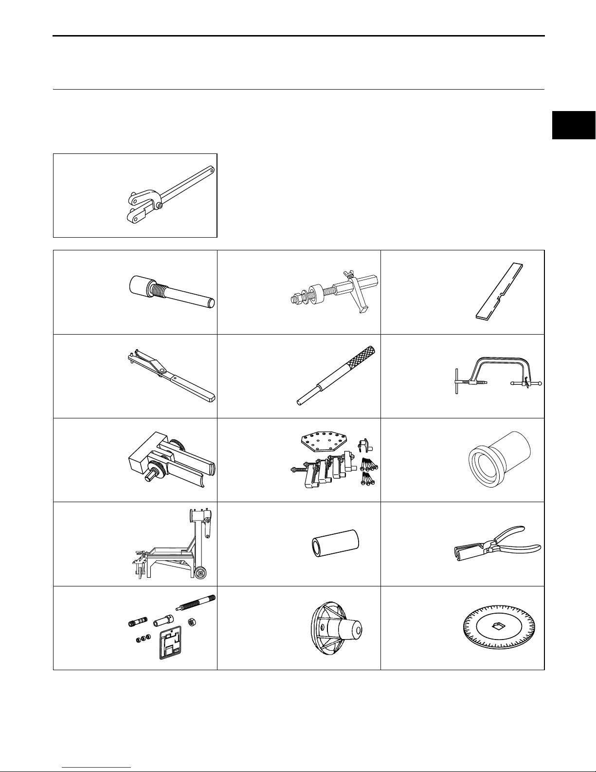
SERVICE TOOLS
01–60 SERVICE TOOLS
ENGINE SST . . . . . . . . . . . . . . . . . . . . . . 01–60–1
End of Toc
ENGINE SST
1: Mazda SST number
2: Global SST number
Example
1:49 UN20 5072
2:205–072
Holder
E5U016002000E01
01–60
1: –
2:303–507
Crankshaft TDC
setting peg
1:49 G032 354
2: –
Adjusting
wrench
1:49 B012 0A2
2: –
Pivot
1:49 0107 680A
2: –
Engine stand
1:49 E011 1A0
2: –
Ring gear brake
set
1:49 B012 015
2: –
Valve guide
installer
1:49 L010 1A0
2: –
Engine hanger
set
1:49 T032 302
2: –
Bearing installer
1:49 UN30 3465
2: 303–465
Camshaft
Alignment
timing Tool
1:49 0636 100B
2: –
Valve spring
lifter arm
1:49 H010 401
2: –
Oil seal installer
1:49 S120 170
2: –
Valve seal
remover
1:49 L012 0A0B
2: –
Valve seal and
valve guide
installer set
1:49 UN30 3328
2: 303-328
Rear oil seal
replacer
1:49 D032 316
2: –
Protractor
01–60–1
Page 60
1:49 G011 201
2: –
SERVICE TOOLS
Attachment
End Of Sie
——
01–60–2
 Loading...