

Mazda MX-5 1994 User Manual

1994 Mazda MX-5 Miata
1994 Mazda MX-5 Miata
D - ADJUSTMENTS 1994 ENGINE PERFORMANCE Mazda - On-Vehicle Adjustments
D - ADJUSTMENTS 1994 ENGINE PERFORMANCE Mazda - On-Vehicle Adjustments
D - ADJUSTMENTS
1994 ENGINE PERFORMANCE Mazda - On-Vehicle Adjustments
ENGINE MECHANICAL
Before performing any on-vehicle adjustments to fuel or ignition systems, ensure engine mechanical condition
is okay.
VALVE CLEARANCE
NOTE: All piston engines are equipped with hydraulic valve lash adjusters. Valve
clearance is not adjustable.
IGNITION TIMING
NOTE: Before adjusting ignition timing, warm engine to normal operating temperature.
Turn off all accessories. Place transmission in Neutral (M/T) or Park (A/T).
Ensure idle speed is correct. See IDLE SPEED under IDLE SPEED & MIXTURE. If
timing is not within specification, loosen distributor or Crank Angle Sensor
(CAS) lock bolt. Rotate distributor or CAS until timing marks are aligned.
Tighten lock bolt.

1994 Mazda MX-5 Miata
D - ADJUSTMENTS 1994 ENGINE PERFORMANCE Mazda - On-Vehicle Adjustments
Courtesy of MAZDA MOTORS CORP.
NOTE: On Miata, use Blue 1-pin connector near airflow meter as a source of battery
power for positive lead of tachometer or timing light (battery is in trunk). DO
NOT ground this connector, or 20-amp WIPER fuse will blow.
1. Connect Diagnostic Tester (49 B019 9A0) to diagnostic connector and select SELF-TEST mode (position
1), or connect jumper wire between diagnostic connector terminals TEN and GND. See Fig. 2 .
2. Connect timing light. Set timing to specification. See IGNITION TIMING SPECIFICATIONS table.
See Fig. 1 . Disconnect diagnostic tester or jumper wire from diagnostic connector.
Fig. 2: Diagnostic Connector Terminal ID (Miata)

1994 Mazda MX-5 Miata
D - ADJUSTMENTS 1994 ENGINE PERFORMANCE Mazda - On-Vehicle Adjustments
Courtesy of MAZDA MOTORS CORP.
IGNITION TIMING SPECIFICATIONS
Application M/T
Miata
(2)
(1)
Place automatic transmission in Park.
(2)
Connect jumper wire between terminals TEN and GRN of diagnostic connector.
10 @ 850 10 @ 800
(1)
A/T
IDLE SPEED & MIXTURE
NOTE: Mixture adjustment is NOT a normal tune-up procedure. DO NOT adjust mixture
unless mixture control unit is replaced or vehicle fails emissions test.
NOTE: Idle mixture is not adjustable. If idle mixture is incorrect, see TESTS W/CODES
article in the ENGINE PERFORMANCE section.
IDLE SPEED
NOTE: Before adjusting idle speed, warm engine to normal operating temperature.
Turn off all accessories. Place transmission in Neutral (M/T) or Park (A/T).
Ensure ignition timing is adjusted. See IGNITION TIMING .
NOTE: On Miata, use Blue 1-pin connector near airflow meter as a source of battery
power for positive lead of tachometer or timing light (battery is in trunk). DO
NOT ground this connector, or 20-amp WIPER fuse will blow.
1. Connect Diagnostic Tester (49 B019 9A0) to diagnostic connector and select SELF-TEST mode, or
connect jumper wire between diagnostic connector terminals TEN and GND. See Fig. 2 . Connect
tachometer to diagnostic connector terminal IG (-).
2. If idle speed is not within specification, rotate idle air adjusting screw on throttle body. See IDLE SPEED
SPECIFICATIONS table. Disconnect jumper wire.
IDLE SPEED SPECIFICATIONS
Application M/T: RPM
Miata
(2)
(1)
Place automatic transmission in Park.
850 800
(1)
A/T: RPM
(2)
Connect jumper wire between terminals TEN and GRN of diagnostic connector.
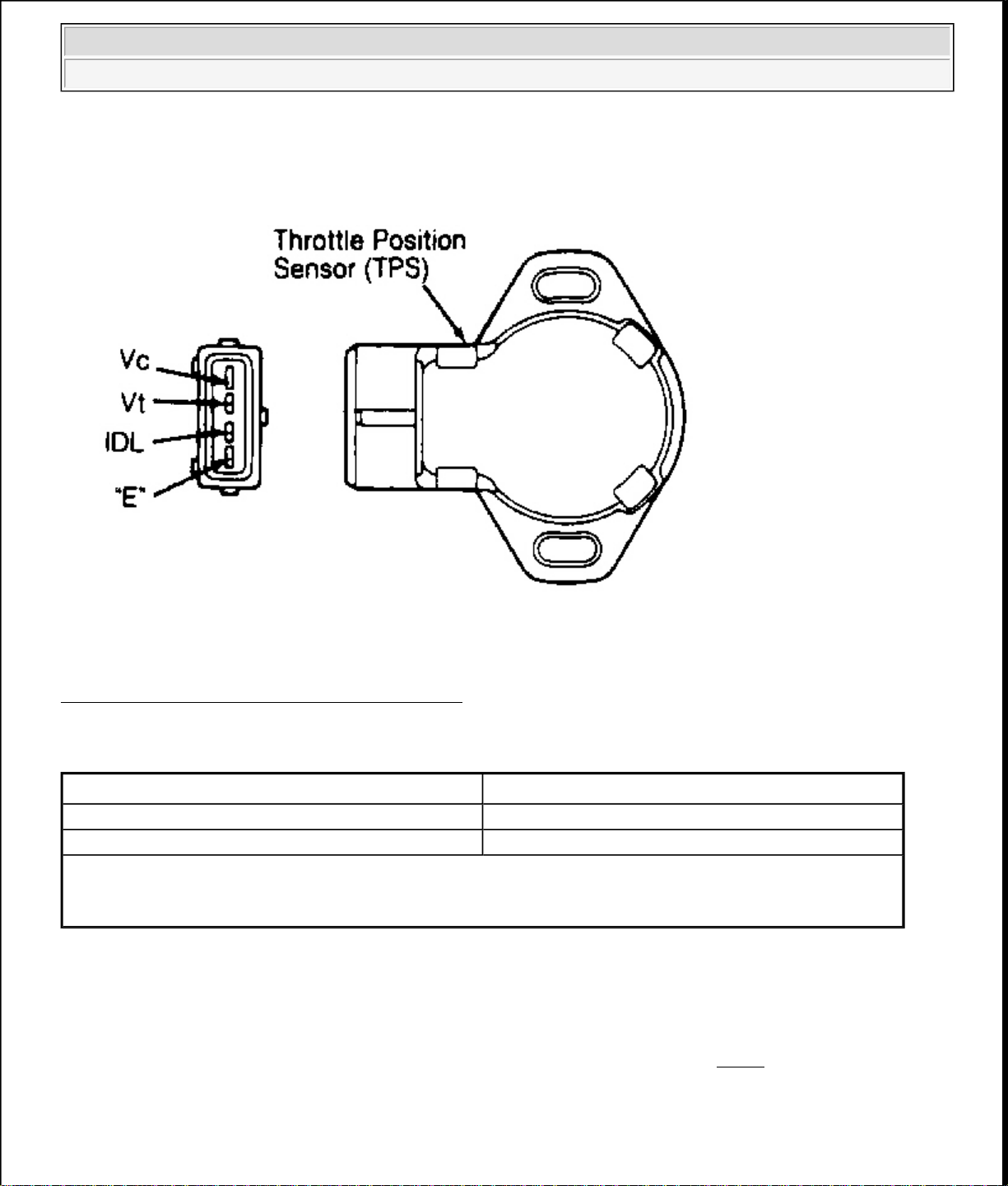
THROTTLE POSITION (TP) SENSOR

1994 Mazda MX-5 Miata
D - ADJUSTMENTS 1994 ENGINE PERFORMANCE Mazda - On-Vehicle Adjustments
INSPECTION (A/T)
1. Disconnect TP sensor connector. Connect ohmmeter between TP sensor connector terminals "E" and
IDL. See Fig. 3
. Insert feeler gauge of specified thickness between throttle lever and throttle stop screw.
See TP SENSOR CONTINUITY (A/T) table.
2. If continuity is not as specified, adjust TP sensor. See ADJUSTMENT procedure. If continuity is as
specified, connect ohmmeter between TP sensor connector terminals Vt and "E". If resistance is less than
1000 ohms with throttle fully closed and about 5000 ohms with throttle wide open, TP sensor is adjusted.
If resistance is not as specified, adjust TP sensor. See ADJUSTMENT procedure.
NOTE: If ohmmeter reading indicates a rough transition anywhere in range between
lowest and highest readings, TP sensor potentiometer is faulty. Replace TP
sensor.
ADJUSTMENT
1. Disconnect TP sensor connector. Connect ohmmeter between TP sensor connector terminals "E" and
IDL. See Fig. 3
. Loosen TP sensor attaching screws.
2. Insert a .010" (.25 mm) feeler gauge between throttle lever and throttle stop screw. Rotate TP sensor
clockwise about 30 degrees, then rotate counterclockwise until ohmmeter indicates continuity.
3. Remove feeler gauge. Insert a .016" (.40 mm) feeler gauge between throttle lever and throttle stop screw.
If ohmmeter indicates no continuity, go to next step. If ohmmeter indicates continuity, repeat adjustment
procedure.
4. Tighten TP sensor attaching screws. Open throttle valve fully and verify resistance between terminals "E"
and Vt is about 5000 ohms.
1994 Mazda MX-5 Miata
D - ADJUSTMENTS 1994 ENGINE PERFORMANCE Mazda - On-Vehicle Adjustments
Fig. 3: TP Sensor Connector Terminal ID (A/T)
Courtesy of MAZDA MOTORS CORP.
TP SENSOR CONTINUITY
Test Condition
(1)
(2)
Continuity
.004" (.10 mm) Yes
.024" (.60 mm) No
(1)
Insert feeler gauge of specified thickness between throttle lever and throttle stop screw.
(2)
Check continuity with ohmmeter connected between TP sensor terminals "E" and IDL.
INSPECTION (M/T)
1. Disconnect TP sensor connector. Insert feeler gauge of specified thickness between throttle lever and
throttle stop screw. See TP SENSOR CONTINUITY (M/T) table.
2. Connect ohmmeter between specified terminals of TP sensor connector. See Fig. 4 . If continuity is not as
specified, adjust TP sensor. See ADJUSTMENT procedure.
ADJUSTMENT
1. Disconnect TP sensor connector. Connect ohmmeter between terminals IDL and TL/E of TP sensor

1994 Mazda MX-5 Miata
D - ADJUSTMENTS 1994 ENGINE PERFORMANCE Mazda - On-Vehicle Adjustments
connector. See Fig. 4 . Insert a .016" (.41 mm) feeler gauge between throttle lever and throttle stop screw.
2. Loosen TP sensor screws. Rotate TP sensor clockwise about 30 degrees, then rotate counterclockwise
until ohmmeter indicates continuity.
3. Remove feeler gauge. Insert a .027" (.69 mm) feeler gauge between throttle lever and throttle stop screw.
If ohmmeter indicates no continuity, go to next step. If ohmmeter indicates continuity, repeat adjustment
procedure.
4. Tighten TP sensor attaching screws. Open throttle valve fully a few times. Recheck TP sensor adjustment.
Fig. 4: TP Sensor Connector Terminal ID (M/T)
Courtesy of MAZDA MOTORS CORP.
TP SENSOR CONTINUITY
Condition
.016" (.41 mm)
.027" (.7 mm)
(1)
(1)
Continuity Between IDL
& TL/E
Yes No
No No
Continuity Between POW &
TL/E
WOT No Yes
Insert feeler gauge of specified thickness between throttle lever and throttle stop screw.

1994 Mazda MX-5 Miata
D - ADJUSTMENTS 1994 ENGINE PERFORMANCE Mazda - On-Vehicle Adjustments
(1)
THROTTLE (IDLE) SWITCH
NOTE: Throttle switch is either a part of TP sensor, which is adjusted automatically
when TP is adjusted, or a separate, nonadjustable switch on throttle body. See
THROTTLE POSITION (TP) SENSOR .

p
1994 Mazda MX-5 Miata
1994 Mazda MX-5 Miata
AIR BAG RESTRAINT SYSTEM 1994 ACCESSORIES/SAFETY EQUIPMENT Mazda Air Bags
AIR BAG RESTRAINT SYSTEM 1994 ACCESSORIES/SAFETY EQUIPMENT Mazda Air Bags
AIR BAG RESTRAINT SYSTEM
1994 ACCESSORIES/SAFETY EQUIPMENT Mazda Air Bags
DESCRIPTION & OPERATION
WARNING: To avoid injury from accidental air bag deployment, read and carefully
follow all WARNINGS and SERVICE PRECAUTIONS.
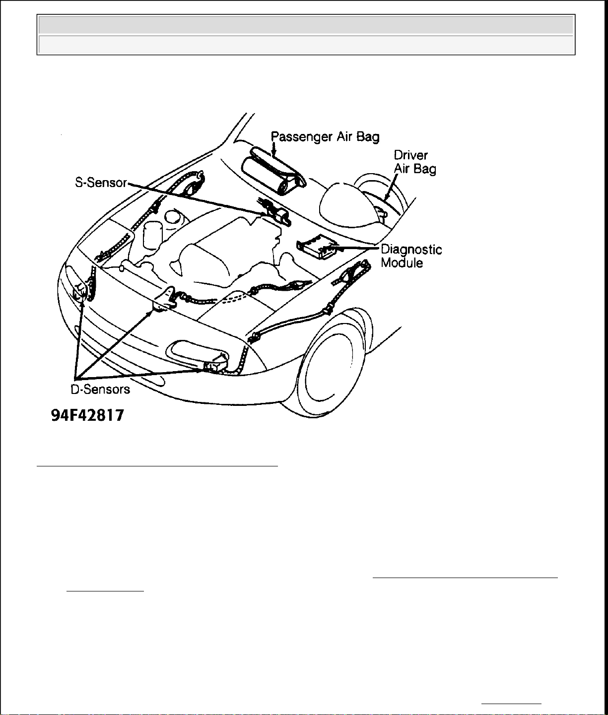
The Supplemental Restraint System (SRS), when used in conjunction with seat belt, provides increased
rotection for driver and passenger in a collision. The air bag restraint system consists of AIR BAG warning
light, driver's air bag module, passenger's air bag module, clockspring, diagnostic module, back-up battery
(located inside diagnostic module), 4 crash sensors and wiring harness. One crash sensor (S-sensor) is located
above heater unit in passenger compartment. Three other crash sensors (D-sensor) are located left front, right
front, and center front of vehicle. See Fig. 1 .
The air bag is designed to deploy when S-sensor (rear) and at least one D-sensor (front) close in a collision
when ignition is on. The back-up battery supplies current for the ignitor if the vehicle battery or fuses fail
during a collision.
The diagnostic module monitors the air bag system for failures. If diagnostic module detects a short between air
bag module and ground or a malfunction with S-sensor or any D-sensor, diagnostic module will melt system
fuse to prevent unintended air bag deployment. If a failure occurs, the diagnostic module turns on the AIR BAG
warning light. If AIR BAG warning light is burned out, diagnostic module will sound a buzzer to alert driver of
a system malfunction.
g
1994 Mazda MX-5 Miata
AIR BAG RESTRAINT SYSTEM 1994 ACCESSORIES/SAFETY EQUIPMENT Mazda Air Bags
Fig. 1: Identifying Air Bag System Components
Courtesy of MAZDA MOTORS CORP.
SERVICE PRECAUTIONS
Following precautions should be observed when working with air bag systems:
Disable SRS before servicing any SRS or steering column component. Failure to do this could result in
accidental air bag deployment and possible personal injury. See DISABLING & ACTIVATING AIR
BAG SYSTEM .
After an accident, all SRS components, including harness and brackets, must be inspected. If any
components are damaged or bent, they must be replaced, even if a deployment did not occur. Check
steering column, knee bolster, instrument panel steering column reinforcement plate and lower brace for
damage. DO NOT service any component or wiring. If components or wiring are damaged or defective,
replacement is necessary. DO NOT use components from another vehicle. Only use new replacement
parts.
After repairs, turn ignition on while ensuring any accidental air bag deployment will not cause injury.
Ensure SRS indicator li
ht is working properly and no system faults are indicated. See TESTING -

p
1994 Mazda MX-5 Miata
AIR BAG RESTRAINT SYSTEM 1994 ACCESSORIES/SAFETY EQUIPMENT Mazda Air Bags
SYSTEM OPERATION CHECK .
Always wear safety glasses when servicing or handling an air bag.
Air bag module must be stored in its original special container until used for service. It must be stored in
a clean, dry place, away from sources of extreme heat, sparks and high electrical energy.
When placing a live air bag module on a bench or other surface, always face air bag and trim cover up,
away from surface. This will reduce motion of module if it is accidentally deployed.
After deployment, air bag surface may contain deposits of sodium hydroxide, which can irritate skin.
Always wear safety glasses, rubber gloves and long-sleeved shirt during clean-up, and wash hands using
mild soap and water. Follow correct disposal procedures. See DISPOSAL PROCEDURES .
NEVER allow any electrical source near inflator on back of air bag module.
If the ignition is on, DO NOT bump the SRS unit. This could cause the air bags to deploy.
When carrying a live air bag module, trim cover should be pointed away from your body to minimize
injury in case of deployment.
DO NOT probe a wire through insulator; this will damage wire and eventually cause failure due to
corrosion.
When performing electrical tests, always use specified digital multimeter and SRS test harnesses
recommended by manufacturer. See SPECIAL TOOLS. DO NOT directly probe the component
connector pins or wires.
When installing SRS wiring harnesses, ensure they will not be pinched or interfere with other vehicle
components.
Inspect all ground connections. Ensure they are clean and tight.
DO not use any type of electrical equipment not specified by manufacturer. See SPECIAL TOOLS.
If SRS is not fully functional for any reason, vehicle should not be driven until system is repaired. DO
NOT remove any component or in any way disable system from operating normally. If SRS is not
functional, park vehicle until repairs can be made.
DISABLING & ACTIVATING AIR BAG SYSTEM
WARNING: After disabling air bag system, wait at least 10 minutes before servicing.
Air bag system voltage is maintained for about 10 minutes after system is
disabled. Failure to wait at least 10 minutes may cause accidental air bag
deployment and possible personal injury.
PROCEDURES
Disabling System
Cancel radio anti-theft function. See CANCELING & ACTIVATING RADIO ANTI-THEFT under
DISABLING & ACTIVATING AIR BAG SYSTEM. Disconnect and shield negative battery cable. Wait at
least 10 minutes for back-up power supply to be depleted. Remove cover panel below left side of instrument
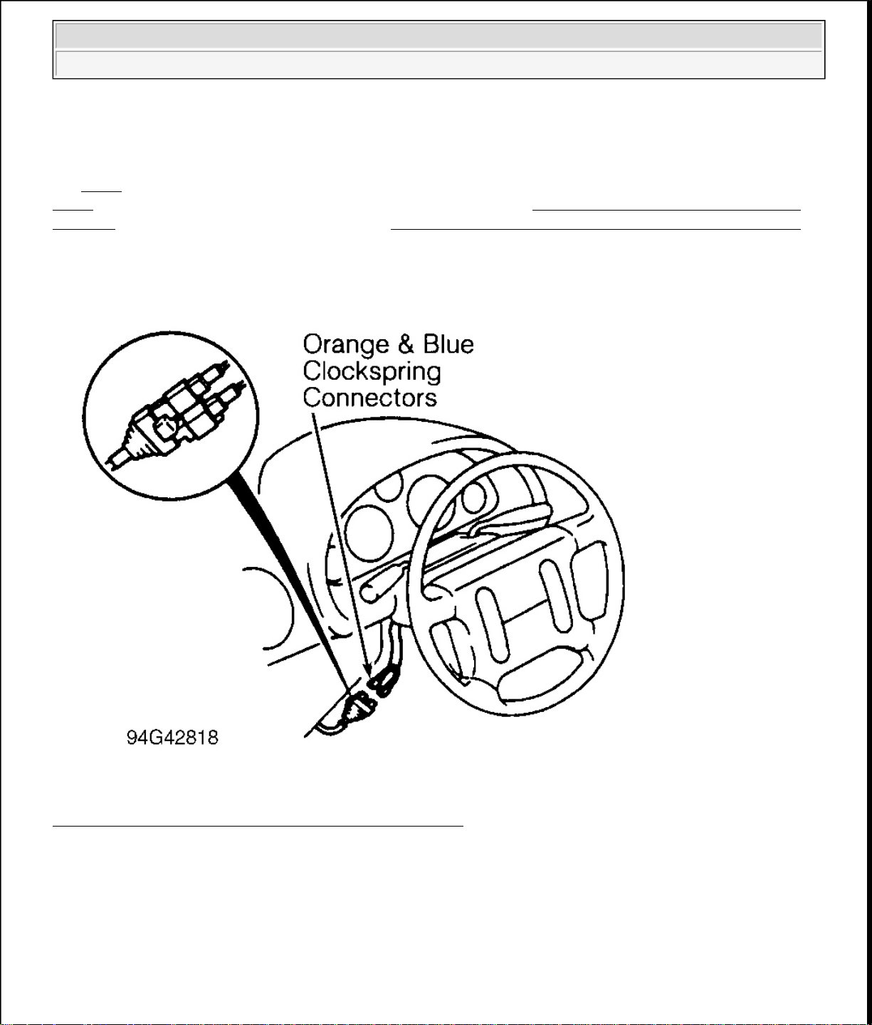
anel. Disconnect Orange and Blue clockspring connectors for driver air bag. See Fig. 2 . Remove glove
compartment. Disconnect Orange and Blue passenger air bag module connectors. See Fig. 3
.
1994 Mazda MX-5 Miata
AIR BAG RESTRAINT SYSTEM 1994 ACCESSORIES/SAFETY EQUIPMENT Mazda Air Bags
Activating System
Ensure negative battery cable is disconnected. Connect Orange and Blue passenger air bag module connectors.
See Fig. 3
. Install glove compartment. Connect driver air bag Orange and Blue clockspring connectors. See
Fig. 2 . Install lower cover panel. Connect negative battery cable. See TESTING - SYSTEM OPERATION
CHECK . Activate radio anti-theft function. See CANCELING & ACTIVATING RADIO ANTI-THEFT
under DISABLING & ACTIVATING AIR BAG SYSTEM.
Fig. 2: Locating Driver Air Bag Clockspring Connectors
Courtesy of MAZDA MOTORS CORP.

1994 Mazda MX-5 Miata
AIR BAG RESTRAINT SYSTEM 1994 ACCESSORIES/SAFETY EQUIPMENT Mazda Air Bags
Fig. 3: Locating Passenger Air Bag Clockspring Connectors
Courtesy of MAZDA MOTORS CORP.
CANCELING & ACTIVATING RADIO ANTI-THEFT
Canceling
1. Obtain radio anti-theft code from vehicle owner. Turn ignition on. Push REW and FF until radio displays
bars. Use channel preset buttons 1-4 to enter current code number.
2. Use preset button 1 to enter first digit of code, preset button 2 to enter second digit of code, etc. After
entering all 4 digits of code, press and hold REW and FF for approximately 2 seconds until a beep is
heard.
3. Radio will display CODE for approximately 5 seconds, then disappear to indicate radio is operative with
anti-theft function by-passed. If radio displays ERR, repeat procedure.
NOTE: If 3 consecutive errors are made during activation of radio anti-theft, radio will
become completely inoperable. If this happens, contact Panasonic.
Activating

1994 Mazda MX-5 Miata
AIR BAG RESTRAINT SYSTEM 1994 ACCESSORIES/SAFETY EQUIPMENT Mazda Air Bags
1. Turn ignition on. Press REW and FF until radio displays bars. While radio is displaying bars, use channel
preset buttons 1-4 to enter code number.
2. Use preset button 1 to enter first digit of code, preset button 2 to enter second digit of code, etc. After
entering all 4 digits of code, press and hold REW and FF for approximately 2 seconds until a beep is
heard.
3. Radio will display COD with a backwards 9. This display will flash for 5 seconds, then disappear to
indicate radio is operational with anti-theft activated. If radio displays ERR, repeat procedure.
POST-COLLISION INSPECTION
If air bags deployed, replace air bag modules and clockspring. Whether air bags deployed or not, inspect the
following components and replace them if damaged: diagnostic module, impact sensors, instrument panel,
steering column, and steering wheel. DO NOT attempt to repair any component or wiring harness. After
replacing components as necessary, perform TESTING - SYSTEM OPERATION CHECK .
ADJUSTMENTS
CLOCKSPRING CENTERING
Set front wheels in straight-ahead position. Turn clockspring clockwise until it stops (DO NOT force). Return
clockspring 2 3/4 turns counterclockwise until mark on clockspring aligns with steering column cover mark.
DISPOSAL PROCEDURES
DEPLOYED AIR BAG
Wrap deployed air bag module in a plastic bag and dispose of as you would any other part. Wear gloves and
safety glasses when handling air bag module.
SCRAPPED VEHICLE
NOTE: When scrapping vehicles with an undeployed air bag(s), air bag(s) must be
deployed inside vehicle.
Driver Air Bag
1. Before deploying air bag, inspect operating condition of Deployment Tool (49 H066 002). See
INSPECTING DEPLOYMENT TOOL
and away from other vehicles and people. Open doors. Open convertible top (if equipped). Disconnect
negative battery cable.
2. Ensure air bag module is firmly mounted to steering wheel. Remove cover panel below left side of
instrument panel. Disconnect Orange and Blue clockspring connectors for driver air bag. See Fig. 2
3. Connect deployment tool connector "A" to driver air bag clockspring connector. See Fig. 4
deployment tool clip to battery positive terminal. Connect Black deployment tool clip to battery negative
under DISPOSAL PROCEDURES. Ensure vehicle is outside
. Connect Red
.

1994 Mazda MX-5 Miata
AIR BAG RESTRAINT SYSTEM 1994 ACCESSORIES/SAFETY EQUIPMENT Mazda Air Bags
terminal. Verify deployment tool Red light is on.
4. Ensure all persons are at least 20 feet from vehicle. Press deployment tool activation switch to deploy air
bag. Because of heat generated from air bag deployment, wait at least 15 minutes before handling
deployed air bag module.
Passenger Air Bag
1. Before deploying air bag, inspect operating condition of Deployment Tool (49 H066 002). See
INSPECTING DEPLOYMENT TOOL under DISPOSAL PROCEDURES. Ensure vehicle is outside
and away from other vehicles and people. Open doors. Open convertible top (if equipped). Disconnect
negative battery cable.
2. Remove glove compartment. Disconnect Orange and Blue passenger air bag module connectors. See Fig.
3 . Connect deployment tool connector "A" to Orange and Blue passenger air bag connector. See Fig. 4 .
Connect Red deployment tool clip to battery positive terminal. Connect Black deployment tool clip to
battery negative terminal. Verify deployment tool Red light is on.
3. Ensure all persons are at least 20 feet from vehicle. Press deployment tool activation switch to deploy air
bag. Because of heat generated from air bag deployment, wait at least 15 minutes before handling
deployed air bag module.
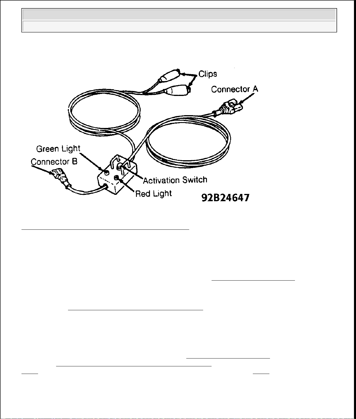
INSPECTING DEPLOYMENT TOOL
NOTE: Deployment tool should always be inspected for proper operation before
deploying air bag.
1. Connect Red deployment tool clip to battery positive terminal. Connect Black deployment tool clip to
battery negative terminal. Observe deployment tool lights. Green light should be on with Red light off.
2. Connect deployment tool connector "A" to connector "B". See Fig. 4 . Green light should be off with Red
light on. Press deployment tool activation switch. Green light should be on with Red light off.
3. If deployment tool lights function as described, it is safe to use deployment tool to activate air bag. If
deployment tool lights do not function as described, DO NOT use deployment tool. Replace deployment
tool with another unit and repeat procedure.
1994 Mazda MX-5 Miata
AIR BAG RESTRAINT SYSTEM 1994 ACCESSORIES/SAFETY EQUIPMENT Mazda Air Bags
Fig. 4: Identifying Air Bag Deployment Tool Connectors
Courtesy of MAZDA MOTORS CORP.
REMOVAL & INSTALLATION
WARNING: Follow air bag service precautions to prevent accidental air bag
deployment and personal injury. See SERVICE PRECAUTIONS .
NOTE: After replacing components, check system to ensure proper operation. See
TESTING
DRIVER AIR BAG MODULE
Removal
Before proceeding, follow air bag service precautions. See SERVICE PRECAUTIONS . Disable air bag
system. See DISABLING & ACTIVATING AIR BAG SYSTEM
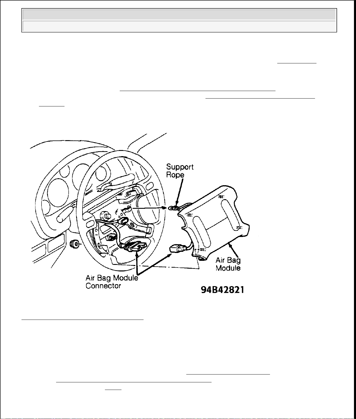
. Disconnect driver air bag module connector. Disconnect support rope. See Fig. 5 . Remove driver air
Fig. 5
bag module.
Installation
- SYSTEM OPERATION CHECK .
. Remove 4 driver air bag module nuts. See
1. With driver air bag module removed from vehicle, connect Orange and Blue clockspring connectors
1994 Mazda MX-5 Miata
AIR BAG RESTRAINT SYSTEM 1994 ACCESSORIES/SAFETY EQUIPMENT Mazda Air Bags
located below left side of instrument panel. Connect negative battery cable. Turn ignition on. Observe
AIR BAG light. If code 32 is set, go to next step. If any code other than 32 is set, see DIAGNOSIS .
2. Turn ignition off. Disconnect negative battery cable. Disconnect Orange and Blue clockspring connectors
located below left side of instrument panel. To install, reverse removal procedure.
3. Activate air bag system. See DISABLING & ACTIVATING AIR BAG SYSTEM . Check AIR BAG
warning light to ensure system is functioning properly. See TESTING
- SYSTEM OPERATION
CHECK .
Fig. 5: Removing Driver Air Bag Module
Courtesy of MAZDA MOTORS CORP.
PASSENGER AIR BAG MODULE
Removal
Before proceeding, follow air bag service precautions. See SERVICE PRECAUTIONS . Disable air bag
system. See DISABLING & ACTIVATING AIR BAG SYSTEM . Remove 4 passenger air bag module nuts.
Disconnect support rope. See Fig. 6
Installation
. Remove passenger air bag module.

1994 Mazda MX-5 Miata
AIR BAG RESTRAINT SYSTEM 1994 ACCESSORIES/SAFETY EQUIPMENT Mazda Air Bags
1. With passenger air bag module removed from vehicle, connect Orange and Blue passenger air bag
module connectors. Connect negative battery cable. Turn ignition on. Observe AIR BAG light. If code 33
is set, go to next step. If any code other than 33 is set, see DIAGNOSIS
.
2. Turn ignition off. Disconnect negative battery cable. Disconnect Orange and Blue passenger air bag
module connectors. To install, reverse removal procedure.
3. Activate air bag system. See DISABLING & ACTIVATING AIR BAG SYSTEM
. Check AIR BAG
warning light to ensure system is functioning properly. See TESTING - SYSTEM OPERATION
CHECK .
Fig. 6: Removing Passenger Air Bag Module
Courtesy of MAZDA MOTORS CORP.
CLOCKSPRING
NOTE: Clockspring is part of combination switch. When replacing clockspring, replace
clockspring and combination switch as an assembly.
Removal

1994 Mazda MX-5 Miata
AIR BAG RESTRAINT SYSTEM 1994 ACCESSORIES/SAFETY EQUIPMENT Mazda Air Bags
1. Set front wheels in straight-ahead position. Before proceeding, follow air bag service precautions. See
SERVICE PRECAUTIONS . Disable air bag system. See DISABLING & ACTIVATING AIR BAG
SYSTEM .
2. Remove driver air bag module. See DRIVER AIR BAG MODULE . Remove steering wheel nut. Using
a puller, remove steering wheel. Remove steering column covers. Remove clockspring screws. Remove
clockspring and combination switch as an assembly.
Installation
1. To install, reverse removal procedure. Before installing steering wheel, center clockspring. See
CLOCKSPRING CENTERING under ADJUSTMENTS. Tighten steering wheel nut to specification.
See TORQUE SPECIFICATIONS TABLE at the end of this article.
2. After installation, activate air bag system. See DISABLING & ACTIVATING AIR BAG SYSTEM .
Check AIR BAG warning light to ensure system is functioning properly. See TESTING - SYSTEM
OPERATION CHECK .
CRASH SENSORS
WARNING: Crash sensor orientation and mounting is important for proper operation.
All sensors must be positioned so arrow points forward. If sheet metal
damage exists near sensor mounting point, inspect body structure at
sensor mounting point for deformation. If structure is damaged, restore it
to original shape.
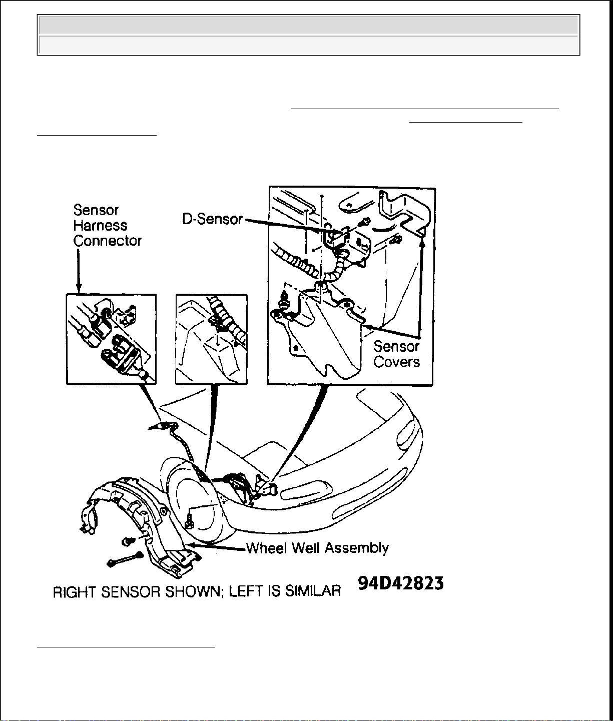
Removal (Front D-Sensors)
1. Before proceeding, follow air bag service precautions. See SERVICE PRECAUTIONS . Disable air bag
system. See DISABLING & ACTIVATING AIR BAG SYSTEM .
2. To remove center sensor, go to step 4). To remove left or right sensor, raise and support front of vehicle.
Remove wheel and tire assembly. Remove wheel well assembly to access sensor.
3. Remove 2 sensor covers. Unbolt sensor from vehicle. Disconnect sensor harness connector located in
front of door jamb area. Remove sensor and harness from vehicle. See Fig. 7
.
4. To remove center sensor, remove top cover located forward of radiator to access sensor. Remove sensor
cover. Unbolt sensor from vehicle. Disconnect sensor harness connector located on top of left wheel well
in engine compartment. Remove sensor and harness from vehicle.
Removal (Rear S-Sensor)
Before proceeding, follow air bag service precautions. See SERVICE PRECAUTIONS . Disable the air bag
system. See DISABLING & ACTIVATING AIR BAG SYSTEM
in passenger compartment. See Fig. 1
. Remove driver and passenger air bag modules. See DRIVER AIR BAG
. Rear S-sensor is located above heater unit
MODULE and PASSENGER AIR BAG MODULE. Remove dashboard assembly to access sensor. Unbolt
sensor from vehicle. Disconnect electrical connectors. Remove sensor from vehicle.
Installation (D-Sensor & S-Sensor)
1994 Mazda MX-5 Miata
AIR BAG RESTRAINT SYSTEM 1994 ACCESSORIES/SAFETY EQUIPMENT Mazda Air Bags
To install, reverse removal procedure. Position sensor with arrow toward front of vehicle. Install air bag
modules (if necessary). Activate air bag system. See DISABLING & ACTIVATING AIR BAG SYSTEM .
Check AIR BAG warning light to ensure system is functioning properly. See TESTING - SYSTEM
OPERATION CHECK .
Fig. 7: Removing Front (D
-Sensor)
Courtesy of MAZDA MOTORS CORP.
DIAGNOSTIC MODULE
Removal & Installation
y
1994 Mazda MX-5 Miata
AIR BAG RESTRAINT SYSTEM 1994 ACCESSORIES/SAFETY EQUIPMENT Mazda Air Bags
1. Before proceeding, follow air bag service precautions. See SERVICE PRECAUTIONS . Disable air bag
system. See DISABLING & ACTIVATING AIR BAG SYSTEM .
2. Diagnostic module is located under left side of instrument panel. See Fig. 1
module connectors. Remove 2 diagnostic module mounting nuts. Remove diagnostic module.
3. To install, reverse removal procedure. After diagnostic module is installed, activate air bag system. See
DISABLING & ACTIVATING AIR BAG SYSTEM
is functioning properly. See TESTING - SYSTEM OPERATION CHECK .
. Check AIR BAG warning light to ensure system
. Disconnect diagnostic
TESTING - SYSTEM OPERATION CHECK
Turn ignition on. AIR BAG warning light in instrument cluster should glow for 4-8 seconds and then turn off. If
AIR BAG warning light does not function as described, a failure has occurred in Supplemental Restraint
System (SRS). Repair malfunctioning SRS. See SERVICE PRECAUTIONS . See DIAGNOSIS .
WIRE REPAIR
DO NOT repair air bag system wiring. If a problem is found with air bag system wiring, replace faulty wiring.
DIAGNOSIS
WARNING: Follow air bag service precautions to prevent accidental air bag
deployment and personal injury. See SERVICE PRECAUTIONS .
SELF-DIAGNOSTIC SYSTEM
NOTE: If AIR BAG warning light does not come on and buzzer sounds when ignition is
turned on, check and repair warning light circuit first.
Diagnostic module will only display one code at a time. Diagnostic module will always display highest code
first. As an example, diagnostic module displays Code 23. After repairing Code 23, if any other codes are
stored, diagnostic module will display next code. Next code displayed will be Code 22 or less. After repairing
system, perform TESTING
during TESTING - SYSTEM OPERATION CHECK , record code displayed. Repair system as necessary.
Retrieving & Clearing Codes
If codes are stored, AIR BAG warning light will flash or remain on when ignition is turned on. Codes are
automatically cleared when fault is corrected.
AIR BAG Warning Light Flashes
AIR BAG warning light indicates fault codes by flashing. Count the number of flashes between pauses to
determine code. See AIR BAG CODES table. Codes are prioritized. If 2 or more faults are present, diagnostic
module will displa
highest code number first. After identifying code, go to appropriate code test.
- SYSTEM OPERATION CHECK . If AIR BAG warning light is still flashing

1994 Mazda MX-5 Miata
AIR BAG RESTRAINT SYSTEM 1994 ACCESSORIES/SAFETY EQUIPMENT Mazda Air Bags
AIR BAG Warning Light Remains On
AIR BAG warning light on all the time when ignition is turned on indicates a Code 0 (zero). See AIR BAG
CODES table.
AIR BAG Warning Light Does Not Come On
Check for blown fuses, burned-out bulb, disconnected diagnostic module or open circuit between warning light
and diagnostic module.
AIR BAG CODES
Code Possible Cause
0
(1)
Poor Connection At Diagnostic Module
12 Open Circuit Or Poor Connection Of Power Source
13 Damaged D-Sensor (D-Sensor On)
21 Poor Installation Of S-Sensor
22 Damaged S-Sensor (S-Sensor On)
23 Open Circuit In S-Sensor Feed Circuit
24 S-Sensor Diagnostic Circuit Open
32 High Resistance Or Open Circuit In Driver Air Bag
Module Circuit
33 High Resistance Or Open Circuit In Passenger Air
Bag Module Circuit
34 Low Resistance In Driver Air Bag Module Circuit
35 Low Resistance In Passenger Air Bag Module
Circuit
41 Open Circuit Between Diagnostic Module And D-
Sensor
44 Poor Installation Of Right D-Sensor
45 Poor Installation Of Center D-Sensor
46 Poor Installation Of Left D-Sensor
51 System Down (Fuse Open)
52 Damaged Back-Up Battery
53 Damaged Diagnostic Module
(2)
99
(1)
AIR BAG warning light remains on all the time indicating a Code 0 (zero).
Poor Connection Of All D-Sensors
(2)
AIR BAG warning light will flash quickly and continuously, indicating Code 99.
CODE 0
Warning Light Remains On

1994 Mazda MX-5 Miata
AIR BAG RESTRAINT SYSTEM 1994 ACCESSORIES/SAFETY EQUIPMENT Mazda Air Bags
1. Disable air bag system. See DISABLING & ACTIVATING AIR BAG SYSTEM . Ensure diagnostic
module connectors are properly connected. Verify that shorting bar is in fully retracted position. Repair as
necessary. If diagnostic module connectors and shorting bar are okay, go to next step.
2. Disconnect diagnostic module connector (with shorting bar). Remove shorting bar from diagnostic
module connector. Observe AIR BAG warning light. If AIR BAG warning light is on, repair wiring
harness between instrument cluster and diagnostic module connector. Perform TESTING
- SYSTEM
OPERATION CHECK . If AIR BAG warning light is off, replace diagnostic module. Perform
TESTING - SYSTEM OPERATION CHECK .
CODE 12
NOTE: For connector terminal identification, see WIRING DIAGRAM .
1. Disable air bag system. See DISABLING & ACTIVATING AIR BAG SYSTEM
. Check INJ fuse (30
amp) located in engine compartment fuse panel. If fuse is okay, go to next step. If fuse is open, go to step
3).
2. Disconnect diagnostic module connectors. Connect negative battery cable. Using a DVOM, measure
voltage on diagnostic module connector terminal 1L. If battery voltage is present, replace diagnostic
module. Perform TESTING
- SYSTEM OPERATION CHECK . If battery voltage is not present,
repair wiring harness between air bag fuse and diagnostic module connector. Perform TESTING -
SYSTEM OPERATION CHECK .
3. Disconnect diagnostic module connectors. Using a DVOM, check for continuity between diagnostic
module connector terminal 1L and ground. If continuity is not present, go to next step. If continuity is
present, replace INJ fuse and repair wiring harness between INJ fuse and diagnostic module connector.
Perform TESTING - SYSTEM OPERATION CHECK .
4. Using a DVOM, check for continuity between diagnostic module connector terminal 1H and ground. If
continuity is present, go to next step. If continuity is not present, replace diagnostic module. Perform
TESTING - SYSTEM OPERATION CHECK .
5. Disconnect S-sensor connector. Using a DVOM, check for continuity between diagnostic module
connector terminal 1H and ground. If continuity is present, replace S-sensor. Perform TESTING -
SYSTEM OPERATION CHECK
. If continuity is not present, replace wiring harness. Perform
TESTING - SYSTEM OPERATION CHECK .
CODE 13
NOTE: For connector terminal identification, see WIRING DIAGRAM
1. Disable air bag system. See DISABLING & ACTIVATING AIR BAG SYSTEM
.
. Connect negative
battery cable. Turn ignition on. Observe AIR BAG warning light. If AIR BAG warning light displays
Code 13, go to step 4). If AIR BAG warning light displays a code other than 13, go to next step.
2. Disconnect negative battery cable. Remove driver air bag module. See DRIVER AIR BAG MODULE
under REMOVAL & INSTALLATION. Connect driver air bag module Orange and Blue clockspring
connectors. Connect negative battery cable. Turn ignition on. Observe AIR BAG warning light. If AIR
BAG warning light displays Code 13, replace clockspring assembly. Perform TESTING - SYSTEM

1994 Mazda MX-5 Miata
AIR BAG RESTRAINT SYSTEM 1994 ACCESSORIES/SAFETY EQUIPMENT Mazda Air Bags
3. Turn ignition off. Disconnect negative battery cable. Connect passenger air bag module Orange and Blue
clockspring connectors. Connect negative battery cable. Turn ignition on. Observe AIR BAG warning
light. If AIR BAG warning light displays Code 13, replace passenger air bag module. Perform TESTING
- SYSTEM OPERATION CHECK . If AIR BAG warning light displays a code other than 13, replace
driver air bag module. Perform TESTING - SYSTEM OPERATION CHECK .
4. Turn ignition off. Disconnect diagnostic module connectors. Using a DVOM, check for continuity
between diagnostic module connector terminal 2F and ground. If continuity is not present, got to next
step. If continuity is present, replace wiring harness. Perform TESTING - SYSTEM OPERATION
CHECK .
5. Using a DVOM, check for continuity between diagnostic module connector terminal 2G and ground. If
continuity is not present, go step XX). If continuity is present, go to next step.
6. Using a DVOM, check for continuity between diagnostic module connector terminal 2D and ground. If
continuity is present, go to next step. If continuity is not present, go to step 8).
7. Disconnect S-sensor connector. Using a DVOM, check for continuity between S-sensor connector (sensor
side) terminal "C" and ground. If continuity is present, replace S-sensor. Perform TESTING - SYSTEM
OPERATION CHECK . If continuity is not present, replace wiring harness. Perform TESTING SYSTEM OPERATION CHECK .
8. Using a DVOM, check resistance between diagnostic module connector terminals 1C, 1A, 2L and ground
one at a time. If resistance on all terminals was 1.18 k-ohms, replace diagnostic module. Perform
TESTING - SYSTEM OPERATION CHECK . If resistance was not 1.18 k-ohms, on one or more
terminals, test suspect D-sensor. See SENSOR IDENTIFICATION table. Go to next step.
SENSOR IDENTIFICATION
Diagnostic Module
Connector Terminal D-Sensor
1A Center
1C Right
2L Left
9. Using a DVOM, check resistance between suspect D-sensor connector (sensor side) terminal "A" and
ground. See Fig. 8 . If resistance is 1.18 k-ohms, replace wiring harness. Perform TESTING - SYSTEM
OPERATION CHECK . If resistance is not 1.18 k-ohms, replace suspect D-sensor. Perform TESTING
- SYSTEM OPERATION CHECK .

1994 Mazda MX-5 Miata
AIR BAG RESTRAINT SYSTEM 1994 ACCESSORIES/SAFETY EQUIPMENT Mazda Air Bags
Fig. 8: Identifying D-Sensor Terminal "A"
Courtesy of MAZDA MOTORS CORP.
CODE 21
NOTE: For connector terminal identification, see WIRING DIAGRAM .
1. Disable air bag system. See DISABLING & ACTIVATING AIR BAG SYSTEM . Disconnect
diagnostic module connectors. Using a DVOM, check for continuity between diagnostic module
connector terminal 1E and ground. If continuity is present, replace diagnostic module. Perform
TESTING
- SYSTEM OPERATION CHECK . If continuity is not present, go to next step.
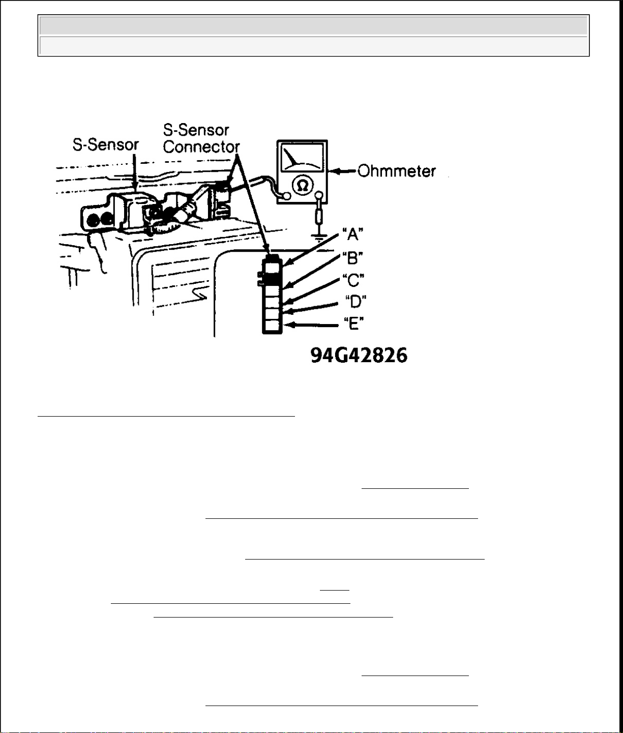
2. Disconnect Orange and Blue S-sensor connector. Using a DVOM, check for continuity between S-sensor
connector (sensor side) terminal "A" and ground. See Fig. 9
harness. Perform TESTING
- SYSTEM OPERATION CHECK . If continuity is not present, replace S-
. If continuity is present, replace wiring
sensor. Perform TESTING - SYSTEM OPERATION CHECK .
1994 Mazda MX-5 Miata
AIR BAG RESTRAINT SYSTEM 1994 ACCESSORIES/SAFETY EQUIPMENT Mazda Air Bags
Fig. 9: Identifying S-Sensor Connector Terminals
Courtesy of MAZDA MOTORS CORP.
CODE 22
NOTE: For connector terminal identification, see WIRING DIAGRAM .
1. Disable air bag system. See DISABLING & ACTIVATING AIR BAG SYSTEM
. Disconnect
diagnostic module connectors. Using a DVOM, check for continuity between diagnostic module
connector terminals 1H and 2D. If continuity is present, go to next step. If continuity is not present,
replace diagnostic module. Perform TESTING - SYSTEM OPERATION CHECK .
2. Disconnect Orange and Blue S-sensor connector. Using a DVOM, check for continuity between S-sensor
connector (sensor side) terminals "B" and "D". See Fig. 9 . If continuity is present, replace S-sensor.
Perform TESTING
harness. Perform TESTING
- SYSTEM OPERATION CHECK . If continuity is not present, replace wiring
- SYSTEM OPERATION CHECK .
CODE 23
NOTE: For connector terminal identification, see WIRING DIAGRAM .
1. Disable air bag system. See DISABLING & ACTIVATING AIR BAG SYSTEM
. Disconnect
diagnostic module connectors. Using a DVOM, check for continuity between diagnostic module
connector terminals 1H and 2C. If continuity is present, replace diagnostic module. Perform TESTING -

1994 Mazda MX-5 Miata
AIR BAG RESTRAINT SYSTEM 1994 ACCESSORIES/SAFETY EQUIPMENT Mazda Air Bags
SYSTEM OPERATION CHECK . If continuity is not present, go to next step.
2. Disconnect Orange and Blue S-sensor connector. Using a DVOM, check for continuity between S-sensor
connector (sensor side) terminals "B" and "E". See Fig. 9
Perform TESTING
- SYSTEM OPERATION CHECK . If continuity is not present, replace S-sensor.
. If continuity is present, replace wiring harness.
Perform TESTING - SYSTEM OPERATION CHECK .
CODE 24
NOTE: For connector terminal identification, see WIRING DIAGRAM .
Disable air bag system. See DISABLING & ACTIVATING AIR BAG SYSTEM . Disconnect diagnostic
module connectors. Using a DVOM, check for continuity between diagnostic module connector terminals 2B
and 2D. If continuity is present, replace diagnostic module. Perform TESTING - SYSTEM OPERATION
CHECK . If continuity is not present, replace wiring harness. Perform TESTING - SYSTEM OPERATION
CHECK .
CODE 32
NOTE: For connector terminal identification, see WIRING DIAGRAM .
1. Disable air bag system. See DISABLING & ACTIVATING AIR BAG SYSTEM . Connect a jumper
wire between driver air bag module clockspring connector (harness side) terminals "B" and "C". See Fig.
10 . Connect negative battery cable. Turn ignition on. Observe AIR BAG warning light. If AIR BAG
warning light displays Code 32, go to step 4). If AIR BAG warning light displays a code other than 32, go
to next step.

1994 Mazda MX-5 Miata
AIR BAG RESTRAINT SYSTEM 1994 ACCESSORIES/SAFETY EQUIPMENT Mazda Air Bags
Fig. 10: Clockspring Connector Terminal ID (Harness Side)
Courtesy of MAZDA MOTORS CORP.
2. Turn ignition off. Disconnect negative battery cable. Remove driver air bag module. See DRIVER AIR
BAG MODULE under REMOVAL & INSTALLATION. Remove jumper wire from driver air bag
module clockspring connector (harness side). Connect driver air bag module Orange and Blue
clockspring connectors. Connect a jumper wire between driver air bag module clockspring connector
terminals "B" and "C". See Fig. 11 .

1994 Mazda MX-5 Miata
AIR BAG RESTRAINT SYSTEM 1994 ACCESSORIES/SAFETY EQUIPMENT Mazda Air Bags
Fig. 11: Identifying Clockspring Connector Terminals
Courtesy of MAZDA MOTORS CORP.
3. Connect negative battery cable. Turn ignition on. Observe AIR BAG warning light. If AIR BAG warning
light displays Code 32, replace clockspring assembly. Perform TESTING
- SYSTEM OPERATION
CHECK . If AIR BAG warning light displays a code other than 32, replace driver air bag module.
Perform TESTING - SYSTEM OPERATION CHECK .
4. Turn ignition off. Disconnect negative battery cable. Disconnect diagnostic module connectors. Using a
DVOM, check for continuity between diagnostic module connector terminals 2D and 2F. If continuity is
present, replace diagnostic module. Perform TESTING - SYSTEM OPERATION CHECK . If
continuity is not present, replace wiring harness. Perform TESTING - SYSTEM OPERATION
CHECK .
CODE 33
NOTE: For connector terminal identification, see WIRING DIAGRAM .
1. Disable air bag system. See DISABLING & ACTIVATING AIR BAG SYSTEM
. Connect a one ohm
resistor (rated power one watt) between driver air bag module clockspring connector (harness side)
terminals "B" and "C". See Fig. 10
. Connect a jumper wire between passenger air bag module connector

1994 Mazda MX-5 Miata
AIR BAG RESTRAINT SYSTEM 1994 ACCESSORIES/SAFETY EQUIPMENT Mazda Air Bags
(harness side) terminals "B" and "C". See Fig. 12 .
2. Connect negative battery cable. Turn ignition on. Observe AIR BAG warning light. If AIR BAG warning
light displays Code 33, go to next step. If AIR BAG warning light displays a code other than 33, replace
passenger air bag module. Perform TESTING - SYSTEM OPERATION CHECK .
Fig. 12: Passenger Air Bag Module Connector Terminal ID (Harness Side)
Courtesy of MAZDA MOTORS CORP.
3. Turn ignition off. Disconnect negative battery cable. Disconnect diagnostic module connectors. Using a
DVOM, check for continuity between diagnostic module connector terminals 2D and 2G. If continuity is
present, replace diagnostic module. Perform TESTING - SYSTEM OPERATION CHECK . If
continuity is not present, replace wiring harness. Perform TESTING
- SYSTEM OPERATION
CHECK .
CODE 34

1994 Mazda MX-5 Miata
AIR BAG RESTRAINT SYSTEM 1994 ACCESSORIES/SAFETY EQUIPMENT Mazda Air Bags
NOTE: For connector terminal identification, see WIRING DIAGRAM
.
1. Disable air bag system. See DISABLING & ACTIVATING AIR BAG SYSTEM . Connect a one ohm
resistor (rated power one watt) between passenger air bag module connector (harness side) terminals "B"
and "C". See Fig. 12 .
2. Connect negative battery cable. Turn ignition on. Observe AIR BAG warning light. If AIR BAG warning
light displays Code 34, go to next step. If AIR BAG warning light displays a code other than 34, go to
step 4).
3. Turn ignition off. Disconnect negative battery cable. Disconnect diagnostic module connectors. Using a
DVOM, check for continuity between diagnostic module connector terminals 2D and 2F. If continuity is
present, replace wiring harness. Perform TESTING
- SYSTEM OPERATION CHECK . If continuity
is not present, replace diagnostic module. Perform TESTING - SYSTEM OPERATION CHECK .
4. Turn ignition off. Disconnect negative battery cable. Remove driver air bag module. See DRIVER AIR
BAG MODULE under REMOVAL & INSTALLATION. Inspect clockspring connector for broken pins.
If clockspring connector pins are okay, go to next step. If clockspring connector pins are broken, replace
clockspring assembly. Perform TESTING - SYSTEM OPERATION CHECK .
5. Connect clockspring connector. Turn ignition on. Observe AIR BAG warning light. If AIR BAG warning
light displays Code 34, replace clockspring assembly. Perform TESTING - SYSTEM OPERATION
CHECK . If AIR BAG warning light does not display Code 34, replace driver air bag module. Perform
TESTING - SYSTEM OPERATION CHECK .
CODE 35
NOTE: For connector terminal identification, see WIRING DIAGRAM .
1. Disable air bag system. See DISABLING & ACTIVATING AIR BAG SYSTEM . Inspect clockspring
connector for broken pins. If clockspring connector pins are okay, go to next step. If clockspring
connector pins are broken, replace clockspring assembly. Perform TESTING - SYSTEM OPERATION
CHECK .
2. Connect a one ohm resistor (rated power one watt) between driver air bag module clockspring connector
(harness side) terminals "B" and "C". See Fig. 10
. Connect negative battery cable. Turn ignition on.
Observe AIR BAG warning light.
3. If AIR BAG warning light displays Code 35, go to next step. If AIR BAG warning light displays a code
other than 35, replace passenger air bag module. Perform TESTING - SYSTEM OPERATION
CHECK .
4. Turn ignition off. Disconnect negative battery cable. Disconnect diagnostic module connectors. Using a
DVOM, check for continuity between diagnostic module connector terminals 2D and 2G. If continuity is
present, replace wiring harness. Perform TESTING
is not present, replace diagnostic module. Perform TESTING
- SYSTEM OPERATION CHECK . If continuity
- SYSTEM OPERATION CHECK .
CODE 41
NOTE: For connector terminal identification, see WIRING DIAGRAM
.
 Loading...