

Page 1
Automatic
CONTENTS
Transaxle and
Transfer
Workshop
Manual
AW6A–EL
AW6AX–EL
FOREWORD
This manual explains the service points for
the above-indicated automotive system.
This manual covers all models with the
above-indicated automotive system, not any
one specific model.
In order to do these procedures safely,
quickly, and correctly, you must first read
this manual and any other relevant service
materials carefully.
All the contents of this manual, including
drawings and specifications, are the latest
available at the time of printing.
As modifications affecting repair or
maintenance occur, relevant information
supplementary to this volume will be made
available at Mazda dealers.
This manual should be kept up-to-date.
Mazda Motor Corporation reserves the right
to alter the specifications and contents of
this manual without obligation or
advance notice.
All rights reserved.
No part of this book may be reproduced or
used in any form or by any means, electronic
or mechanical-including
photocopying and recording and the use of
any kind of information storage and retrieval
system-without permission in writing.
Title
GENERAL INFORMATION
DRIVELINE/AXLE
TRANSMISSION/TRANSAXLE
© 2006 Mazda Motor Corporation
PRINTED IN U.S.A., FEBRUARY 2006
Form No. 1874–1U–06B
Part No. 9999–95–0AW6–07
Section
FEATURES SERVICE
00 00
03 03
05 05
Mazda Motor Corporation
HIROSHIMA, JAPAN
Page 2

Page 3
FEATURES
Page 4

Page 5
DRIVELINE/AXLE
To c o f S C T
OUTLINE . . . . . . . . . . . . . . . . . . 03-00 TRANSFER . . . . . . . . . . . . . . . 03-16
To c o f S C T
03
SECTION
03-00 OUTLINE
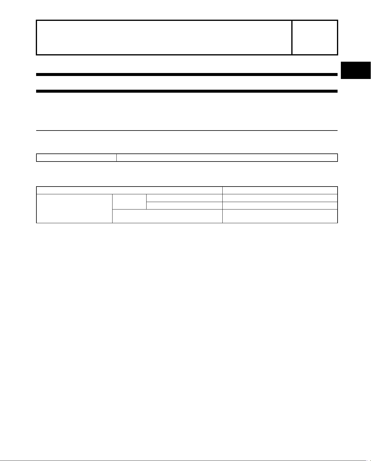
DRIVELINE/AXLE FEATURES . . . . . . . . 03-00–1 DRIVELINE/AXLE SPECIFICATIONS. . . 03-00–1
End of Toc
NG: DRIVELINE/AXLE
DRIVELINE/AXLE FEATURES
Improved reliability • Separate oil pump and oil cooler have been adopted to the transfer
End Of Sie
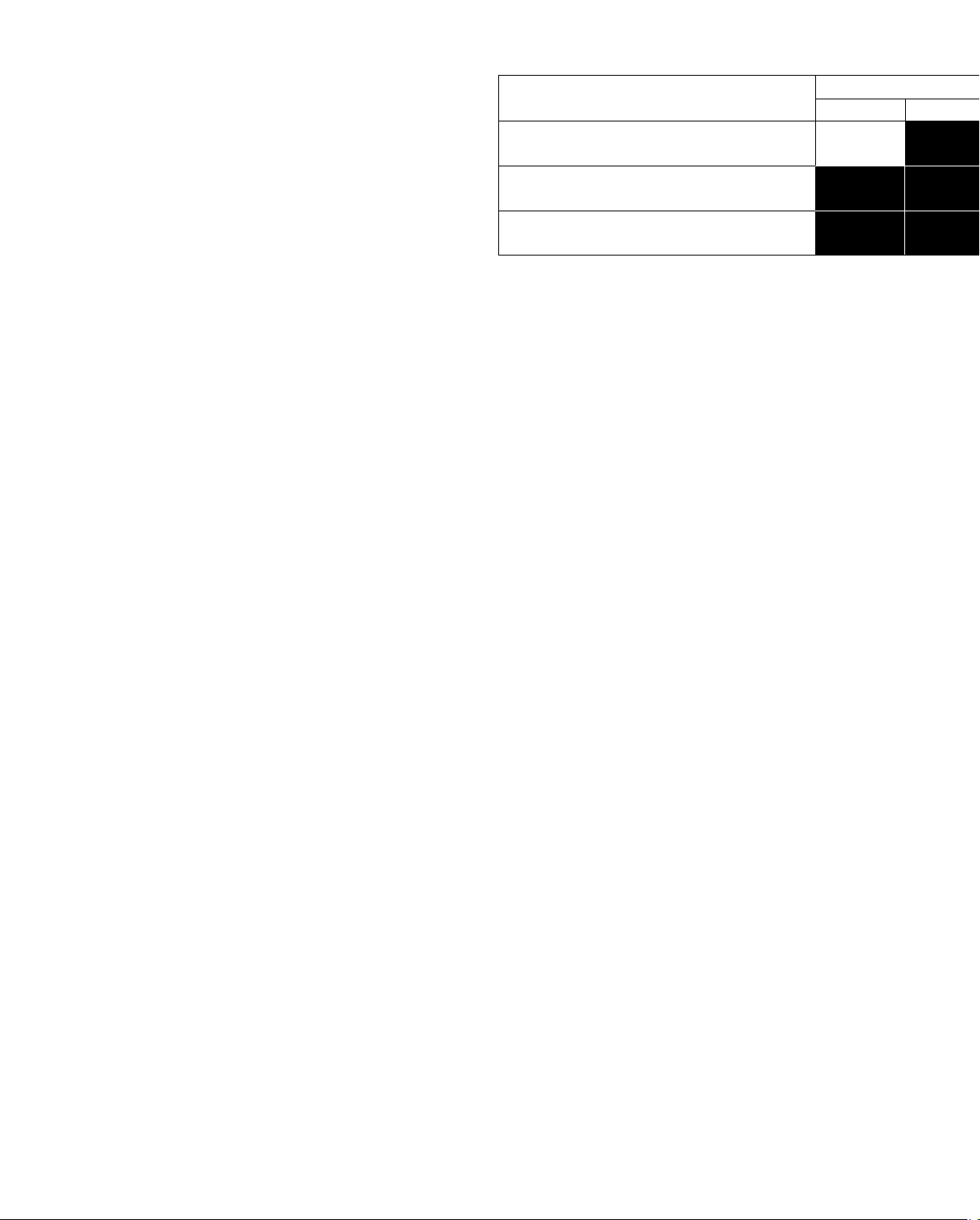
DRIVELINE/AXLE SPECIFICATIONS
Item Specification
Grade API service GL-5
Viscosity SAE 80W-90
(L {US qt, Imp qt}) 1.2 {1.3,1.1}
Transfer oil
Ty p e
Oil capacity
(approx. quantity)
id030000100100
id030000100200
03-00
End Of Sie
03-00–1
Page 6

Page 7
03-16 TRANSFER
TRANSFER
TRANSFER STRUCTURAL VIEW . . . . . 03-16–1
TRANSFER CROSS-SECTIONAL
VIEW. . . . . . . . . . . . . . . . . . . . . . . . . . . 03-16–1
End of Toc
NG: TRANSFER
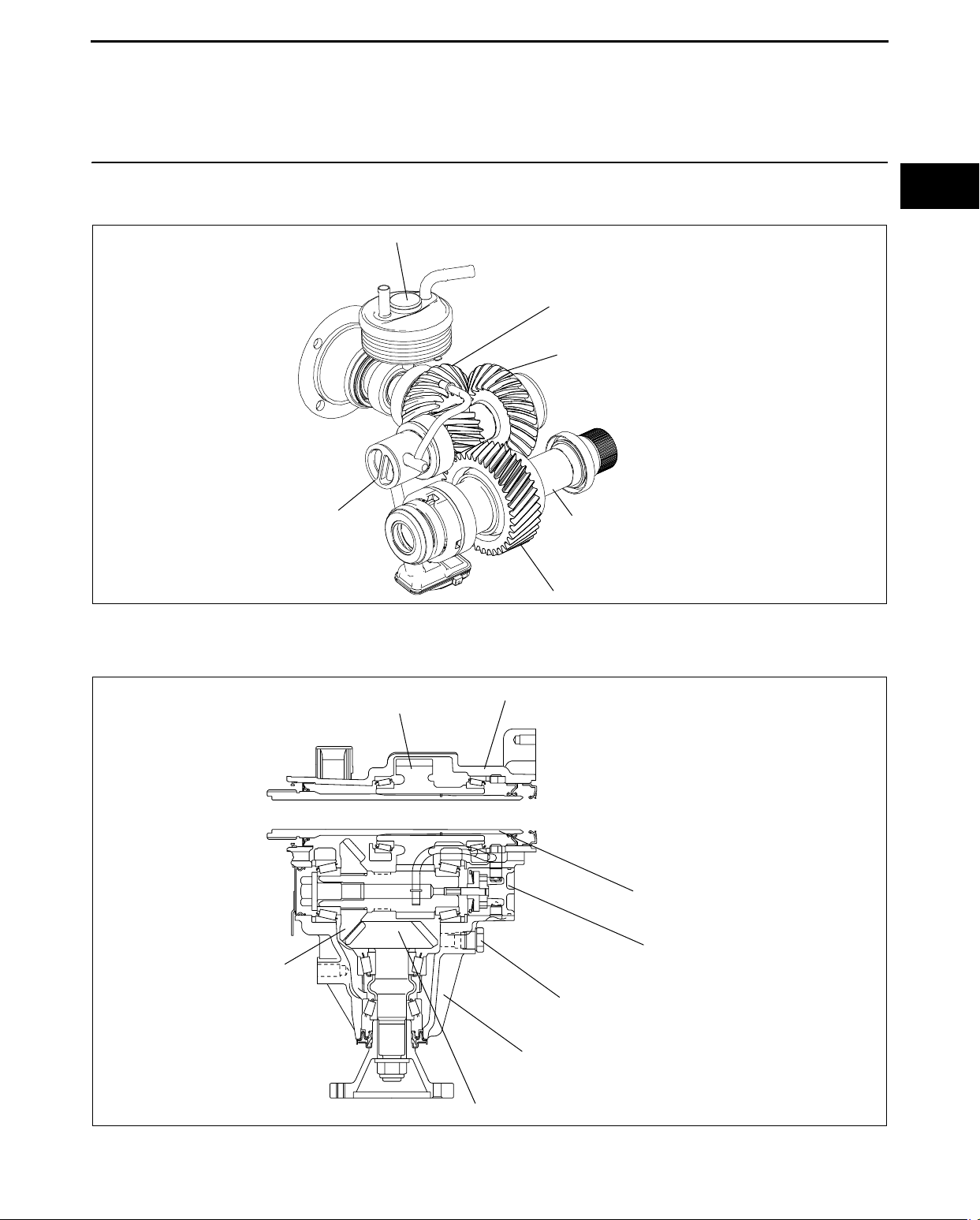
TRANSFER STRUCTURAL VIEW
OIL COOLER
OIL PUMP
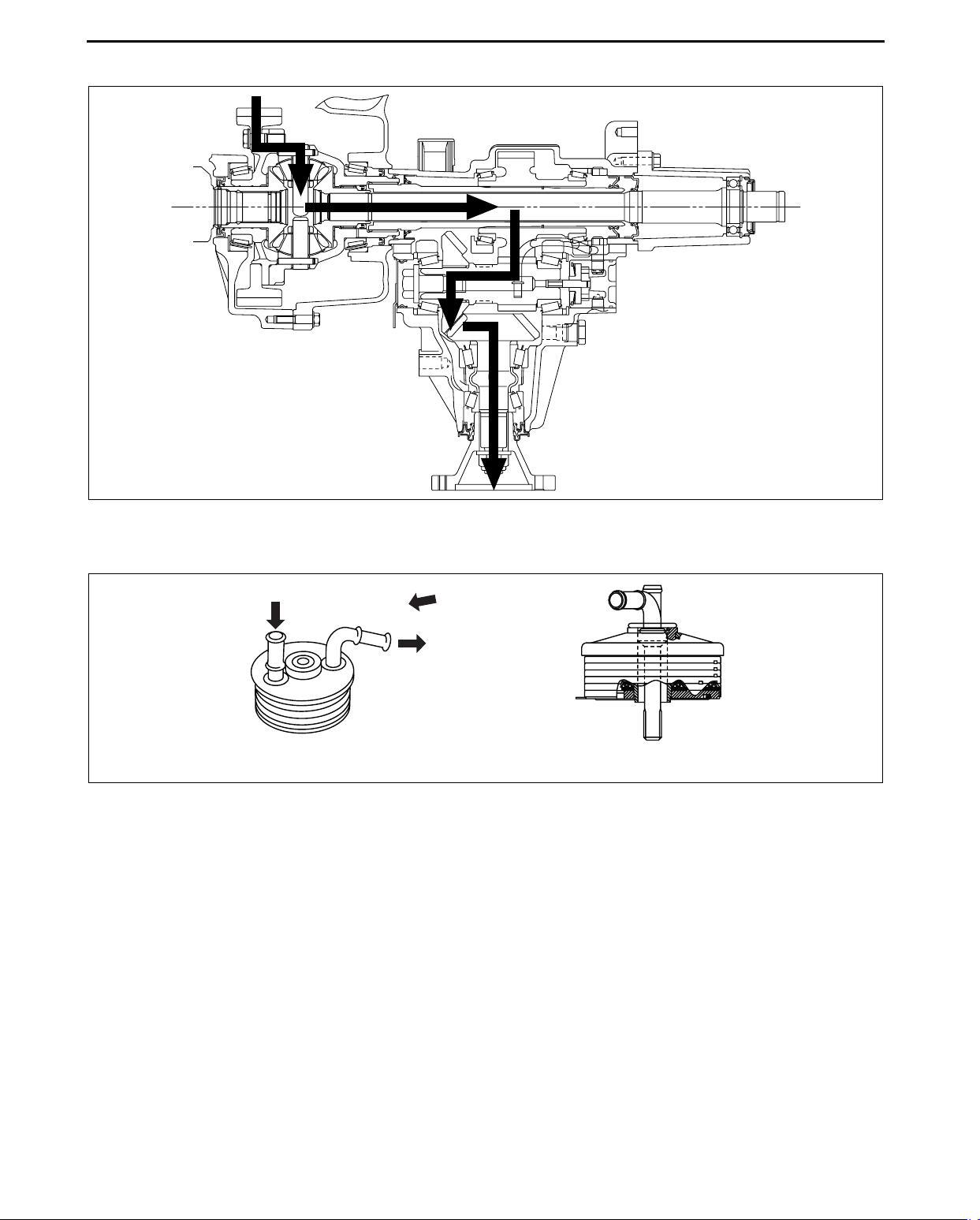
TRANSFER POWER FLOW. . . . . . . . . . . 03-16–2
TRANSFER OIL COOLER
CONSTRUCTION . . . . . . . . . . . . . . . . . 03-16–2
03-16
id031600100100
DRIVE PINION GEAR
RING GEAR
DRIVE GEAR SHAFT
End Of Sie
TRANSFER CROSS-SECTIONAL VIEW
DRIVE GEAR
RING GEAR
DRIVE GEAR
acxuun00000598
id031600100200
DRIVE GEAR CASE
DRIVE GEAR SHAFT
OIL PUMP
OIL LEVEL PLUG
End Of Sie
FRONT CARRIER
DRIVE PINION GEAR
acxuun00000599
03-16–1
Page 8
TRANSFER
TRANSFER POWER FLOW
End Of Sie
TRANSFER OIL COOLER CONSTRUCTION
id031600100300
acxuun00000600
id031600100400
End Of Sie
WATER IN
VIEW A
WATER OUT
VIEW FROM A
acxuun00000601
03-16–2
Page 9
TRANSMISSION/TRANSAXLE
To c o f S C T
OUTLINE . . . . . . . . . . . . . . . . . . 05-00 AUTOMATIC TRANSAXLE . . . 05-17
05
SECTION
To c o f S C T
05-00 OUTLINE
05-00
TRANSMISSION/TRANSAXLE
FEATURES . . . . . . . . . . . . . . . . . . . . . . 05-00–1
End of Toc
NG: TRANSMISSION/TRANSAXLE
TRANSMISSION/TRANSAXLE FEATURES
ATX [AW6A-EL, AW6AX-EL]
Superior shift quality • Centrifugal hydraulic pressure cancel clutch has been adopted.
End Of Sie
AUTOMATIC TRANSAXLE SPECIFICATIONS
Item Specifications
Transaxle type AW6A-EL, AW6AX-EL
1GR 4.148
2GR 2.370
3GR 1.555
Gear ratio
Final gear ratio 3.749
AT F
Torque converter stall torque ratio 2.15
Hydraulic system
(Number of drive/driven plates)
Band servo
(mm {in})
Front planetary gear
(Number of teeth)
Rear planetary gear
(Number of teeth)
Counter drive gear (Number of teeth) 52
Counter gear (Number of teeth)
Ring gear (Number of teeth) 53
• The example of automatic transaxle specifications. (specifications of the CX-7)
End Of Sie
4GR 1.154
5GR 0.859
6GR 0.685
Reverse 3.393
Type JWS3309
Capacity (approx. quantity)
C1 clutch 7/7
C2 clutch 4/4
C3 clutch 4/4
B2 brake 7/6
Servo diameter (piston outer dia./retainer
outer dia.)
Ring gear 81
Sun gear 45
Pinion gear 17
Ring gear 72
Middle sun gear 33
Rear sun gear 27
Long pinion gear 18
Short pinion gear 17
Driven gear 49
Drive gear 15
AUTOMATIC TRANSAXLE
SPECIFICATIONS . . . . . . . . . . . . . . . . 05-00–1
(L {US qt, Imp qt})
7.0 {7.4, 6.2}
61.3/66.0
{2.41/2.60}
id050000100200
id050000100300
05-00–1
Page 10

Page 11

AUTOMATIC TRANSAXLE
05-17 AUTOMATIC TRANSAXLE
AUTOMATIC TRANSAXLE OUTLINE . . 05-17–1
AUTOMATIC TRANSAXLE
CROSS-SECTIONAL VIEW . . . . . . . . . 05-17–2
POWERFLOW STRUCTURE . . . . . . . . . 05-17–4
Description of Components . . . . . . . . . 05-17–4
POWERFLOW OPERATION . . . . . . . . . . 05-17–5
1GR (D range) . . . . . . . . . . . . . . . . . . . 05-17–6
1GR (M range) . . . . . . . . . . . . . . . . . . . 05-17–7
2GR . . . . . . . . . . . . . . . . . . . . . . . . . . . 05-17–8
3GR. . . . . . . . . . . . . . . . . . . . . . . . . . . . 05-17–9
4GR. . . . . . . . . . . . . . . . . . . . . . . . . . . . 05-17–10
5GR. . . . . . . . . . . . . . . . . . . . . . . . . . . . 05-17–11
6GR. . . . . . . . . . . . . . . . . . . . . . . . . . . . 05-17–12
R position . . . . . . . . . . . . . . . . . . . . . . . 05-17–13
CENTRIFUGAL HYDRAULIC PRESSURE
CANCEL CLUTCH OUTLINE . . . . . . . . 05-17–15
TORQUE CONVERTER OUTLINE. . . . . . 05-17–17
End of Toc
NG: AUTOMATIC TRANSAXLE
AUTOMATIC TRANSAXLE OUTLINE
• The AW6A (X) -EL automatic transaxle is a compact, lightweight, next-generation electronically controlled FF 6speed automatic transaxle that employs a Ravigneaux-type planetary gear. It employs a high-precision clutch
hydraulic control system for smooth, highly responsive gear shift feel.
id051700101700
End Of Sie
05-17
05-17–1
Page 12
AUTOMATIC TRANSAXLE
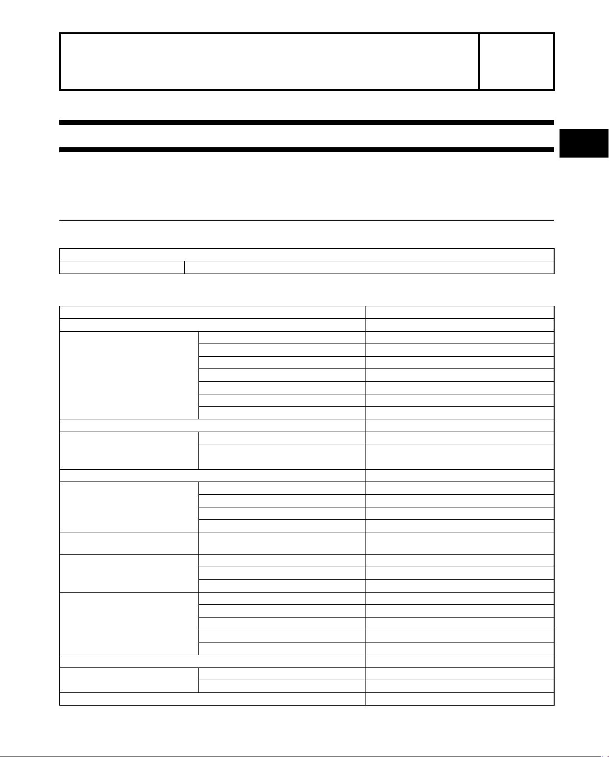
AUTOMATIC TRANSAXLE CROSS-SECTIONAL VIEW
AW6A-EL
C2 CLUTCH C1 CLUTCH C3 CLUTCHB2 BRAKE B1 BRAKE
ONE-WAY
CLUTCH
id051700101900
TORQUE
CONVERTER
COUNTER
DRIVE GEAR
COUNTER GEAR
(DRIVEN)
COUNTER GEAR
(DRIVE)
DIFFERENTIAL
acxuun00000612
05-17–2
Page 13
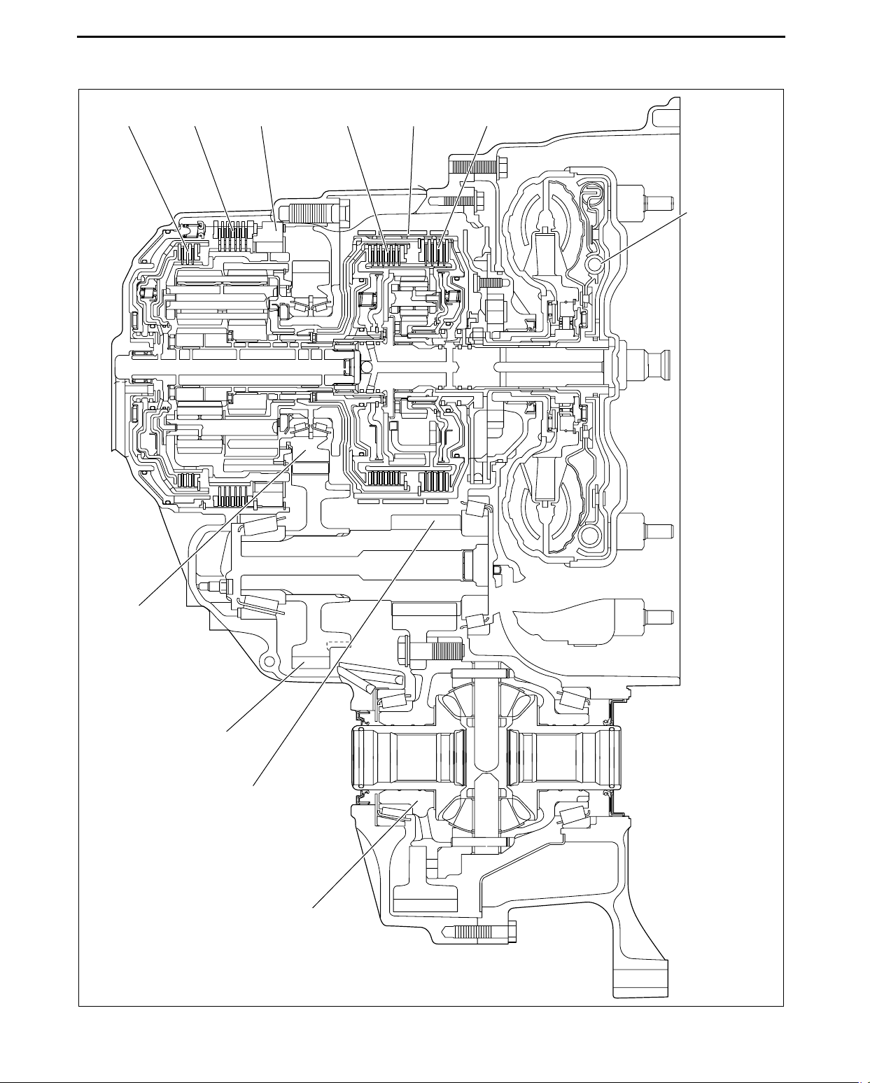
AW6AX-EL
AUTOMATIC TRANSAXLE
C2 CLUTCH C1 CLUTCH C3 CLUTCHB2 BRAKE B1 BRAKE
ONE-WAY
CLUTCH
TORQUE
CONVERTER
05-17
COUNTER
DRIVE GEAR
COUNTER GEAR
(DRIVEN)
COUNTER GEAR
(DRIVE)
DIFFERENTIAL
End Of Sie
acxuun00000613
05-17–3
Page 14
AUTOMATIC TRANSAXLE
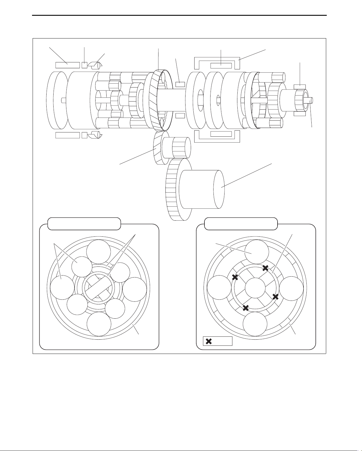
POWERFLOW STRUCTURE
Description of Components
C2 CLUTCH B2 BRAKE
ONE-WAY
CLUTCH
COUNTER GEAR
COUNTER DRIVE GEAR
B1 BRAKE
C1 CLUTCH
id051700102200
C3 CLUTCH
OIL PUMP
INPUT
SHAFT
DIFFERENTIAL
REAR PLANETARY GEAR
SUN GEAR
PINION GEAR
RING GEAR
FRONT PLANETARY GEAR
PINION GEAR
INPUT
SHAFT
: LOCK
• The number of pinion gears differs depending on the engine displacement and vehicle.
— Mazda6
• Front: 3 pinions
• Rear: 3 pinions
— CX-7
• Front: 5 pinions
• Rear: 3 pinions
SUN GEAR
RING GEAR
acxuun00000680
05-17–4
Page 15
AUTOMATIC TRANSAXLE
ONE-WAY CLUTCH
B2 BRAKE
C2 CLUTCH
REAR PLANETARY
LONG PINION
GEAR
REAR
PLANETARY
CARRIER
REAR PLANETARY
RING GEAR
REAR PLANETARY SHORT
PINION GEAR
REAR PLANETARY REAR SUN GEAR
End Of Sie
POWERFLOW OPERATION
List of operating components
Clutch / Brake Operation
C1 clutch • Connects front planetary carrier to rear planetary rear sun gear
C2 clutch • Connects intermediate shaft to rear planetary carrier
C3 clutch • Connects front planetary carrier to rear planetary middle sun gear
B1 brake • Locks rear planetary middle sun gear
B2 brake • Locks rear planetary carrier
One-way clutch • Locks counterclockwise rotation of rear planetary carrier
COUNTER
DRIVE GEAR
REAR PLANETARY
MIDDLE SUN GEAR
C1 CLUTCH
FRONT
PLANETARY
RING GEAR
B1 BRAKE
FRONT
PLANETARY
CARRIER
FRONT PLANETARY SUN GEAR
C3 CLUTCH
FRONT
PLANETARY
PINION GEAR
05-17
acxuun00000681
id051700102300
05-17–5
Page 16
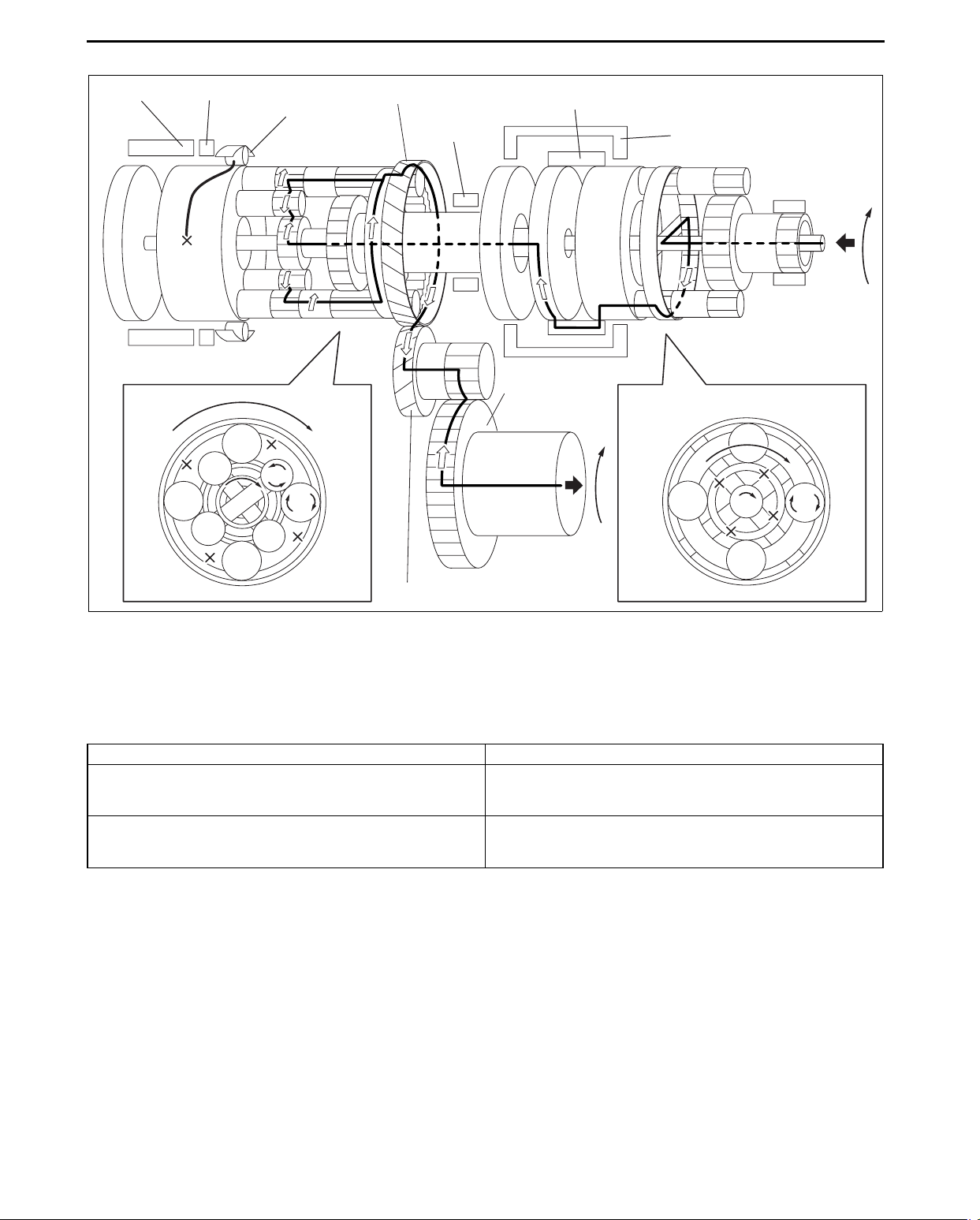
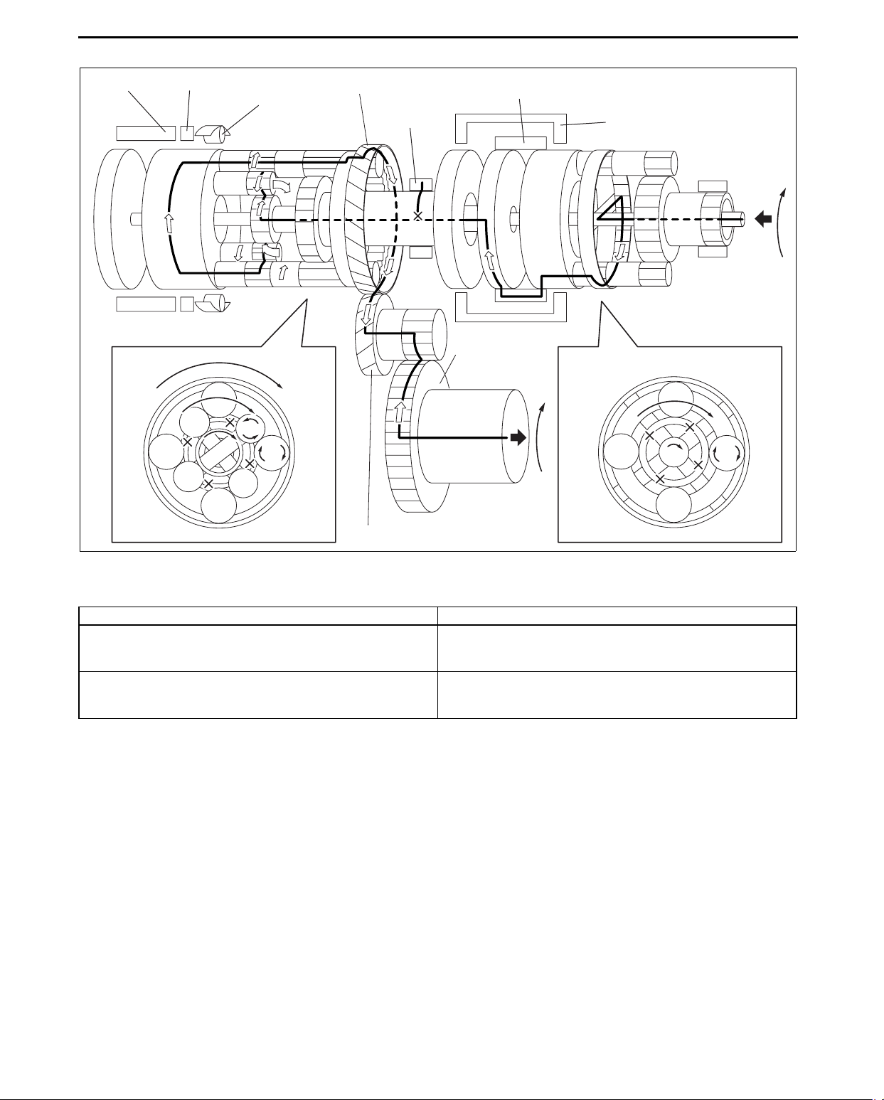
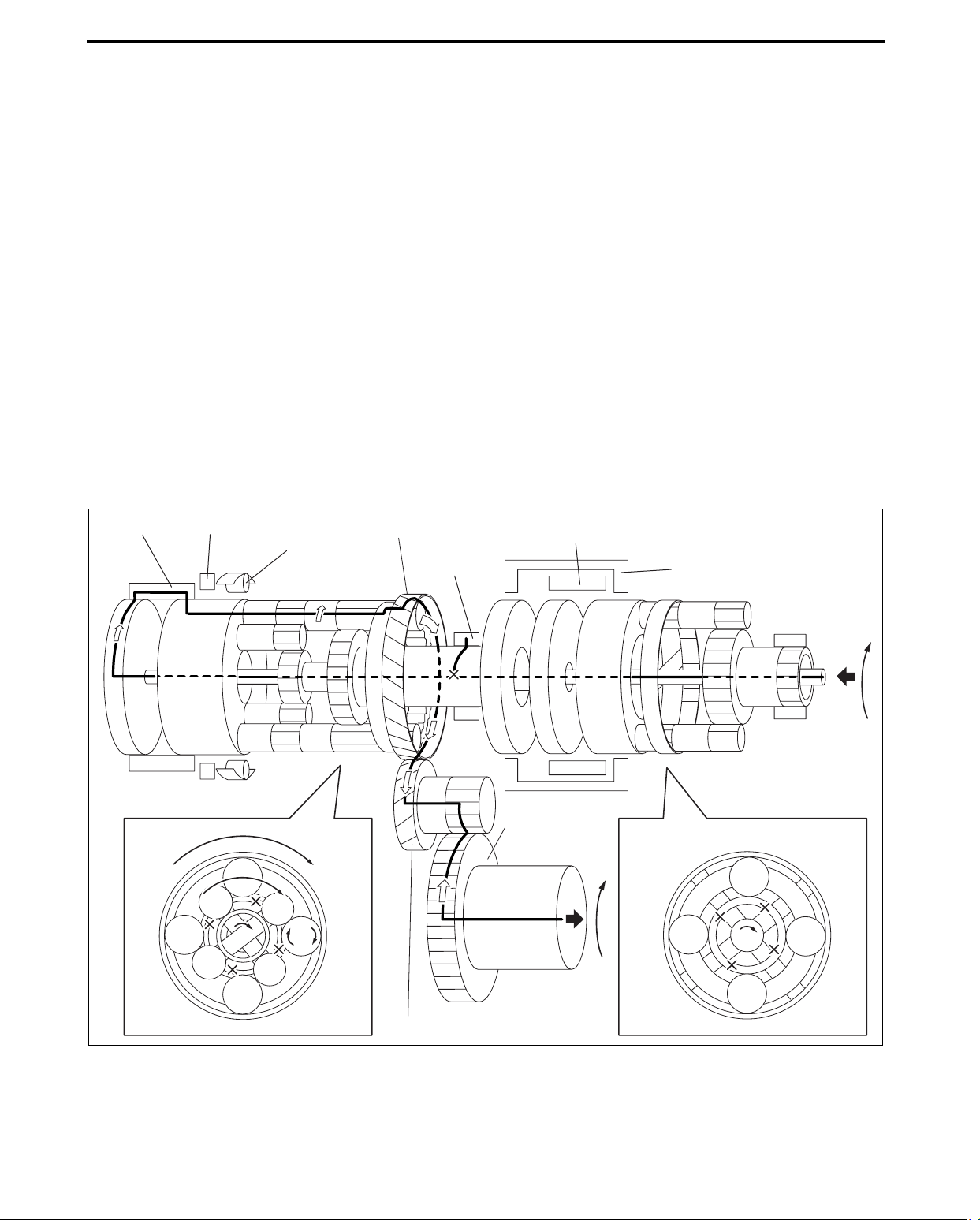
1GR (D range)
AUTOMATIC TRANSAXLE
C2 CLUTCH B2 BRAKE
ONE-WAY
CLUTCH
COUNTER DRIVE GEAR
B1 BRAKE
C1 CLUTCH
C3 CLUTCH
RING GEAR
(DIFFERENTIAL)
COUNTER GEAR
acxuun00000620
Power transmission pathway
[Operating components: C1 clutch, One-way clutch]
• Operating components:
C1 clutch, One-way clutch (counterclockwise rotation is locked), B2 brake (ON when engine brake is operating)
Planetary gear unit Input, Locked, Output
Front
Rear
Input: Ring gear
Locked: Sun gear
Output: Carrier
Input: Rear sun gear
Locked: Carrier
Output: Ring gear
1. Input shaft (rotates clockwise) [same revolutions as the torque converter’s turbine runner]
2. Front planetary ring gear (rotates clockwise) [same revolutions as the input shaft]
3. Front planetary pinion gear (rotates clockwise on its axis, orbits clockwise)
[because the front planetary sun gear is locked by the oil pump, it is pressed against the front planetary ring
gear and orbits the sun gear while rotating on its axis (because the front planetary ring gear has internal gears,
the rotational direction does not change)]
4. Front planetary carrier (rotates clockwise)
[reduction: same revolution as the front planetary pinion gear orbit revolution]
5. C1 clutch (rotates clockwise) [connects the front planetary carrier and the rear planetary rear sun gear]
6. Rear planetary rear sun gear (rotates clockwise) [same revolution as the front planetary carrier]
7. Rear planetary short pinion gear (rotates counterclockwise on its axis)
[the rear planetary carrier tries to rotate counterclockwise, but the counterclockwise rotation is locked by oneway clutch.]
8. Rear planetary long pinion gear (rotates clockwise on its axis)
[the rear planetary middle sun gear rotates counterclockwise (idling)]
05-17–6
Page 17
AUTOMATIC TRANSAXLE
9. Rear planetary ring gear (rotates clockwise)
[the rear planetary ring gear is rotated by the rear planetary long pinion gear (because the rear planetary ring
gear has internal gears, the rotational direction does not change)]
10. Counter drive gear (rotates clockwise)
[because the rear planetary ring gear is installed on the counter drive gear, the rotational direction and the
revolution are the same as the rear planetary ring gear]
11. Counter gear (rotates counterclockwise)
12. Differential ring gear (rotates clockwise)
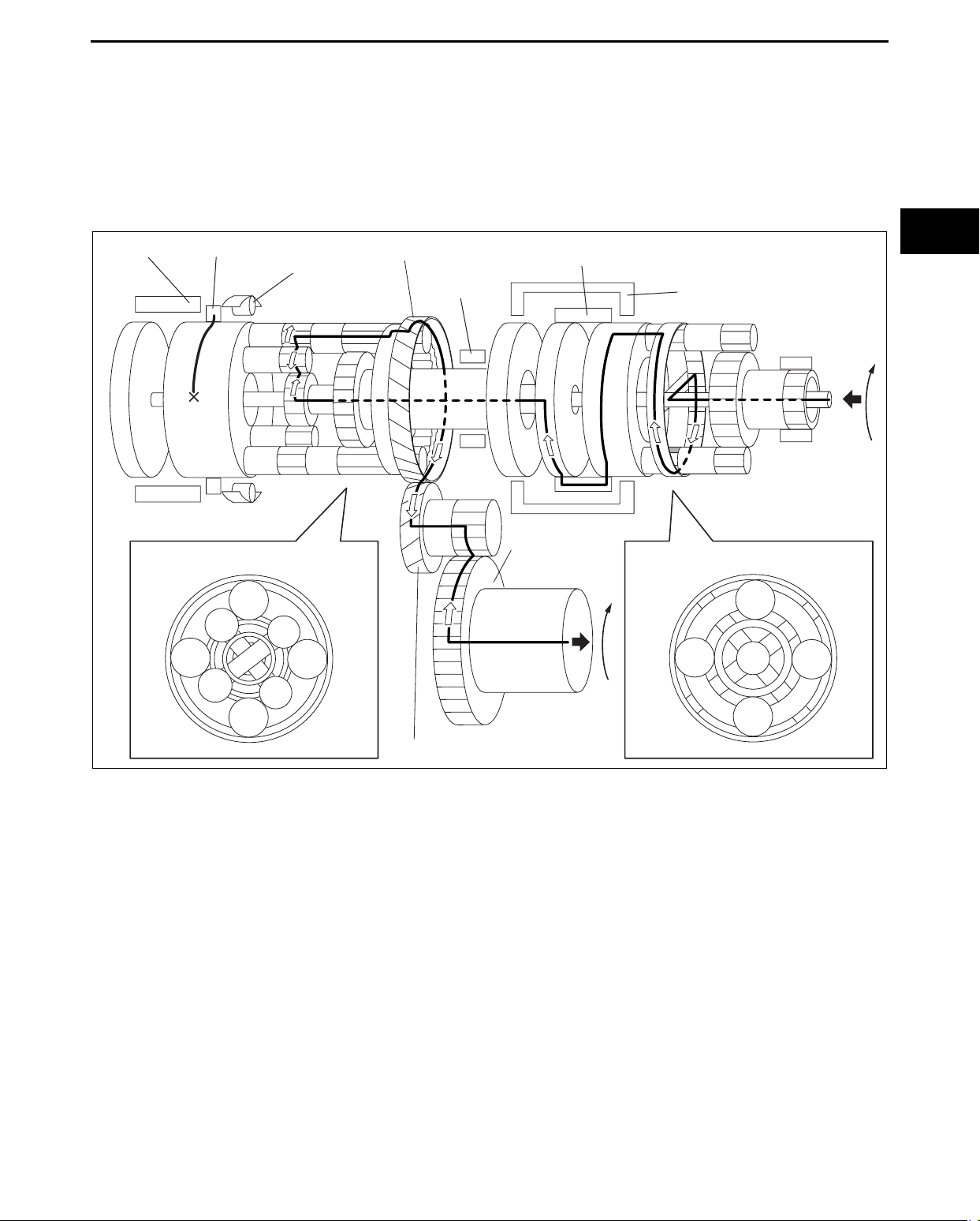
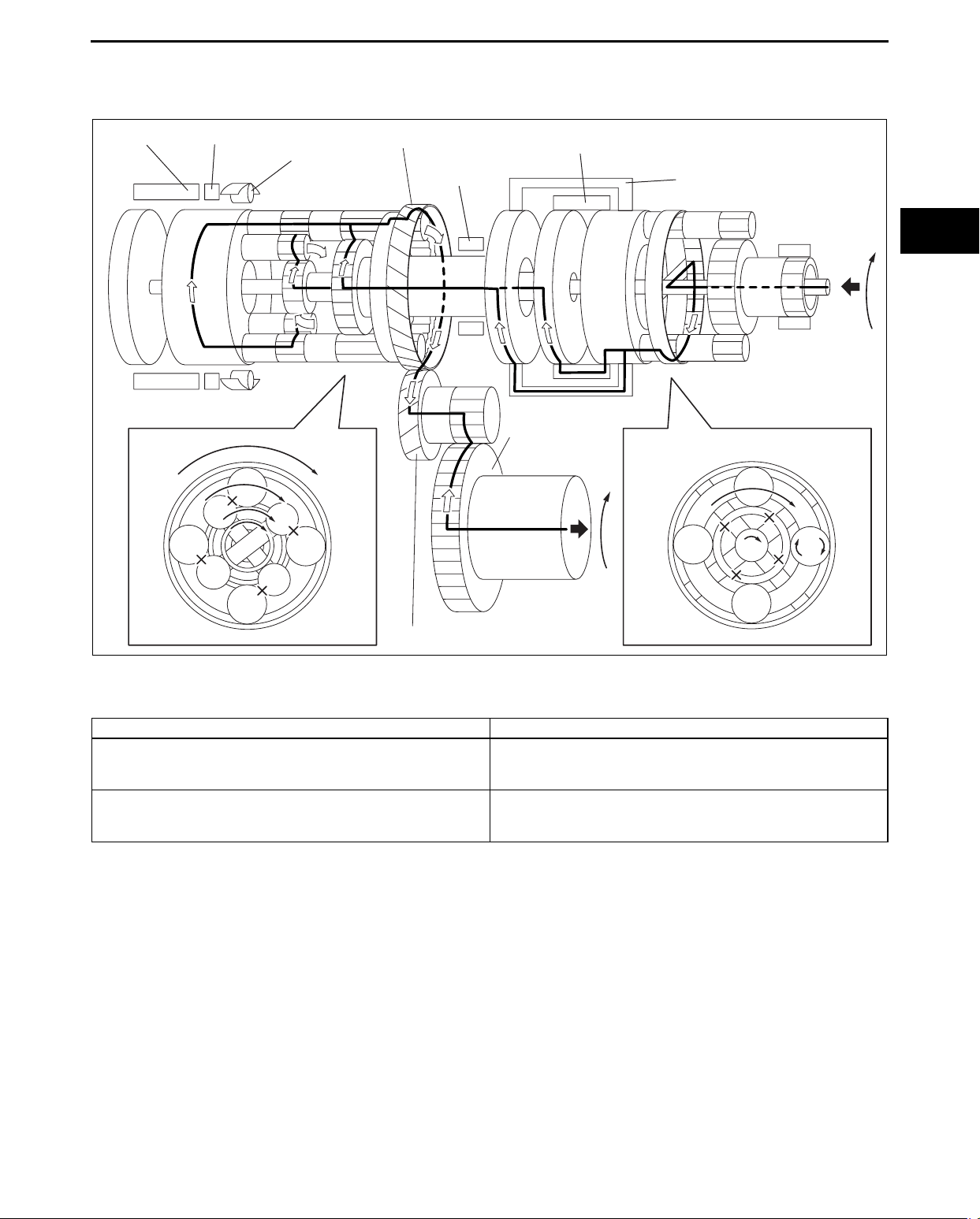
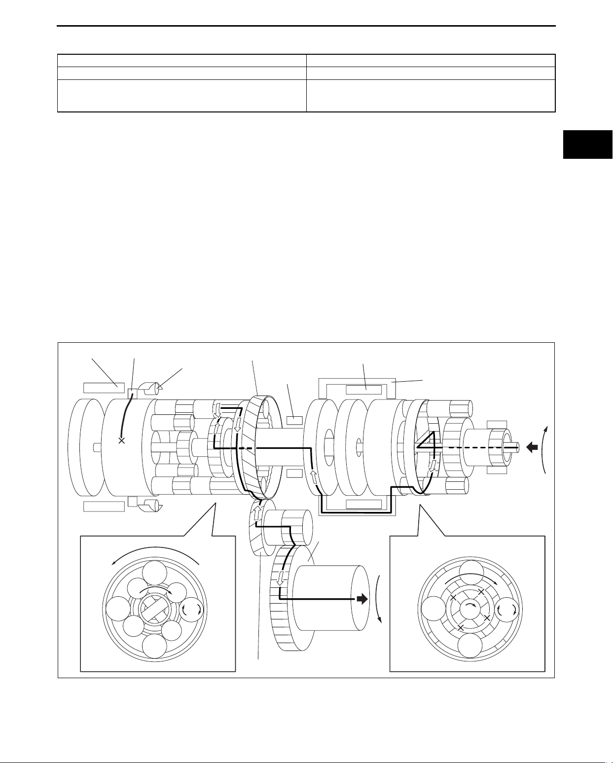
1GR (M range)
C2 CLUTCH B2 BRAKE
ONE-WAY
CLUTCH
COUNTER DRIVE GEAR
B1 BRAKE
05-17
C1 CLUTCH
C3 CLUTCH
RING GEAR
(DIFFERENTIAL)
COUNTER GEAR
acxuun00000621
[Operating components: C1 clutch, B2 brake]
• When the engine brake is operating, driving force is transmitted from the tires. Because the rear planetary
carrier, which is locked in its counterclockwise rotation by the one-way clutch, tries to rotate clockwise, B2 brake
is turned ON and the rear planetary carrier is locked, and kinematic energy is transmitted from the tires to the
engine.
05-17–7
Page 18
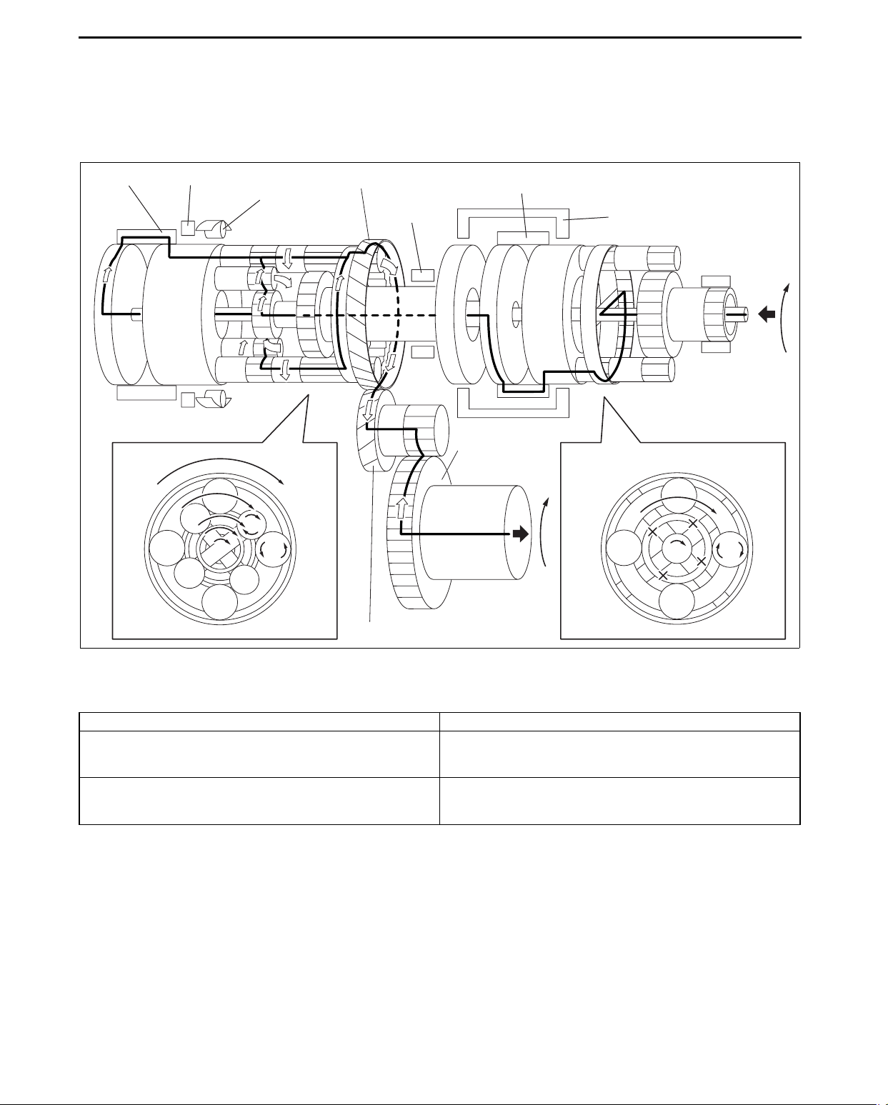
2GR
AUTOMATIC TRANSAXLE
C2 CLUTCH B2 BRAKE
ONE-WAY
CLUTCH
COUNTER DRIVE GEAR
B1 BRAKE
C1 CLUTCH
C3 CLUTCH
RING GEAR
(DIFFERENTIAL)
COUNTER GEAR
acxuun00000622
Power transmission pathway
[Operating components: C1 clutch, B1 brake]
Planetary gear unit Input, Locked, Output
Front
Rear
Input: Ring gear
Locked: Sun gear
Output: Carrier
Input: Rear Sun gear
Locked: Middle Sun gear
Output: Ring gear
1. Input shaft (rotates clockwise) [same revolutions as the torque converter’s turbine runner]
2. Front planetary ring gear (rotates clockwise) [same revolution as the input shaft]
3. Front planetary pinion gear (rotates clockwise on its axis, orbits clockwise)
[because the front planetary sun gear is locked by the oil pump, it is pressed against the front planetary ring
gear and orbits the sun gear while rotating on its axis (because the front planetary ring gear has internal gears,
the rotational direction does not change)]
4. Front planetary carrier (rotates clockwise)
[reduction: same revolution as the front planetary pinion gear orbit revolution]
5. C1 clutch (rotates clockwise) [connects the front planetary carrier and the rear planetary rear sun gear]
6. Rear planetary rear sun gear (rotates clockwise) [same revolution as the front planetary carrier]
7. Rear planetary middle sun gear is locked by B1 brake
8. Rear planetary short pinion gear (rotates counterclockwise on its axis, orbits clockwise)
9. Rear planetary long pinion gear (rotates clockwise on its axis, orbits clockwise)
10. Rear planetary ring gear (rotates clockwise)
[the rear planetary ring gear is rotated by the rear planetary long pinion gear (because the rear planetary ring
gear has internal gears, the rotational direction does not change)]
11. Counter drive gear (rotates clockwise)
[because the rear planetary ring gear is installed on the counter drive gear, the rotational direction and the
revolution are the same as the rear planetary ring gear]
12. Counter gear (rotates counterclockwise)
13. Differential ring gear (rotates clockwise)
05-17–8
Page 19
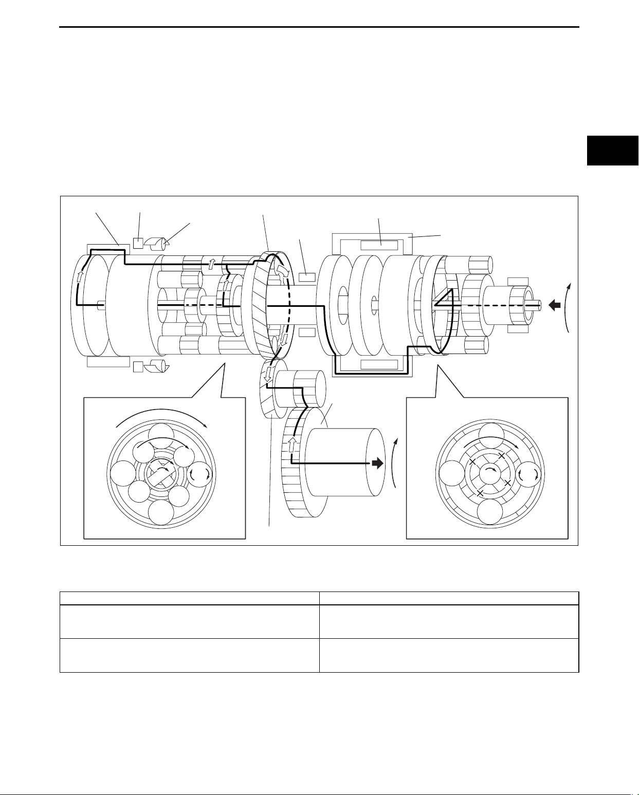
AUTOMATIC TRANSAXLE
Engine brake
• When the engine brake is operating, driving force is transmitted from the tires.
3GR
C2 CLUTCH B2 BRAKE
ONE-WAY
CLUTCH
COUNTER DRIVE GEAR
B1 BRAKE
C1 CLUTCH
C3 CLUTCH
05-17
RING GEAR
(DIFFERENTIAL)
COUNTER GEAR
acxuun00000623
Power transmission pathway
[Operating components: C1 clutch, C3 clutch]
Planetary gear unit Input, Locked, Output
Input: Ring gear
Front
Input: Rear Sun gear, Middle Sun gear
Rear
Locked: Sun gear
Output: Carrier
Locked: -
Output: Ring gear
1. Input shaft (rotates clockwise) [same revolution as the torque converter’s turbine runner]
2. Front planetary ring gear (rotates clockwise) [same revolution as the input shaft]
3. Front planetary pinion gear (rotates clockwise on its axis, orbits clockwise)
[because the front planetary sun gear is locked by the oil pump, it is pressed against the front planetary ring
gear and orbits the sun gear while rotating on its axis (because the front planetary ring gear has internal gears,
the rotational direction does not change)]
4. Front planetary carrier (rotates clockwise)
[reduction: same revolution as the front planetary pinion gear orbit revolution]
5. C1 clutch (rotates clockwise) [connects the front planetary carrier and the rear planetary rear sun gear]
6. C3 clutch (rotates clockwise) [connects the front planetary carrier and the rear planetary middle sun gear]
7. Rear planetary gear component (rotates clockwise)
[because the rear planetary short pinion gear and the rear planetary long pinion gear are engaged, both the
pinion gears are locked due to the difference in the rotational directions, and kinematic energy of the rear
planetary sun gear and rear planetary middle sun gear is transmitted to the rear planetary ring gear]
8. Rear planetary ring gear (rotates clockwise) [same revolution as the rear planetary carrier]
9. Counter drive gear (rotates clockwise)
[because the rear planetary ring gear is installed on the counter drive gear, the rotational direction and the
revolution are same as the rear planetary ring gear]
05-17–9
Page 20
AUTOMATIC TRANSAXLE
10. Counter gear (rotates counterclockwise)
11. Differential ring gear (rotates clockwise)
Engine brake
• When the engine brake is operating, driving force is transmitted from the tires.
4GR
C2 CLUTCH B2 BRAKE
ONE-WAY
CLUTCH
COUNTER DRIVE GEAR
B1 BRAKE
C1 CLUTCH
C3 CLUTCH
RING GEAR
(DIFFERENTIAL)
COUNTER GEAR
acxuun00000624
Power transmission pathway
[Operating components: C1 clutch, C2 clutch]
Planetary gear unit Input, Locked, Output
Front
Rear
Input: Ring gear
Locked: Sun gear
Output: Carrier
Input: Rear Sun gear, Carrier
Locked: -
Output: Ring gear
1. Input shaft (rotates clockwise) [same revolution as the torque converter’s turbine runner]
2. Front planetary ring gear (rotates clockwise) [same revolution as the input shaft]
3. Front planetary pinion gear (rotates clockwise on its axis, orbits clockwise)
[because the front planetary sun gear is locked by the oil pump, it is pressed against the front planetary ring
gear and orbits the sun gear while rotating on its axis (because the front planetary ring gear has internal gears,
the rotational direction does not change)]
4. Front planetary carrier (rotates clockwise)
[reduction: same revolution as the front planetary pinion gear orbit revolution]
5. C1 clutch (rotates clockwise) [connects the front planetary carrier and the rear planetary rear sun gear]
6. Intermediate shaft (rotates clockwise) [same revolution as the input shaft]
7. C2 clutch (rotates clockwise) [same revolution as the intermediate shaft]
8. Rear planetary carrier (rotates clockwise) [same revolution as the intermediate shaft]
9. Rear planetary short pinion gear (rotates clockwise on its axis, orbits clockwise)
[because the rear planetary carrier rotates faster than the rear planetary sun gear]
05-17–10
Page 21
AUTOMATIC TRANSAXLE
10. Rear planetary long pinion gear (rotates counterclockwise on its axis, orbits clockwise)
11. Rear planetary ring gear (rotates clockwise)
[because the rear planetary long pinion gear’s rotation is subtracted from the rear planetary carrier revolution,
the rear planetary ring gear revolution is slower than those of the rear planetary carrier]
12. Counter drive gear (rotates clockwise)
[because the rear planetary ring gear is installed on the counter drive gear, the rotational direction and the
revolution is the same as the rear planetary ring gear]
13. Counter gear (rotates counterclockwise)
14. Differential ring gear (rotates clockwise)
Engine brake
• When the engine brake is operating, driving force is transmitted from the tires.
5GR
C2 CLUTCH B2 BRAKE
ONE-WAY
CLUTCH
COUNTER DRIVE GEAR
B1 BRAKE
C1 CLUTCH
RING GEAR
(DIFFERENTIAL)
05-17
C3 CLUTCH
COUNTER GEAR
acxuun00000625
Power transmission pathway
[Operating components: C2 clutch, C3 clutch]
Planetary gear unit Input, Locked, Output
Input: Ring gear
Front
Rear
Locked: Sun gear
Output: Carrier
Input: Carrier, Middle Sun gear
Locked: -
Output: Ring gear
1. Input shaft (rotates clockwise) [same revolutions as torque converter’s turbine runner]
2. Front planetary ring gear (rotates clockwise) [same revolution as the input shaft]
3. Front planetary pinion gear (rotates clockwise on its axis, orbits clockwise)
[because the front planetary sun gear is locked by the oil pump, it is pressed against the front planetary ring
gear and orbits the sun gear while rotating on its axis (because the front planetary ring gear has internal gears,
the rotational direction does not change)]
05-17–11
Page 22
AUTOMATIC TRANSAXLE
4. Front planetary carrier (rotates clockwise)
[reduction: same revolution as the front planetary pinion gear orbit revolution]
5. C3 clutch (rotates clockwise) [connects the front planetary carrier and the rear planetary middle sun gear]
6. Rear planetary middle sun gear (rotates clockwise)
[same revolution as C3 clutch (decelerates by the front planetary gear, so the revolutions are slower than the
input shaft)]
7. Intermediate shaft (rotates clockwise) [same revolution as the input shaft]
8. C2 clutch (rotates clockwise) [same revolution as the intermediate shaft]
9. Rear planetary carrier (rotates clockwise) [same revolutions as intermediate shaft]
10. Rear planetary long pinion gear (rotates clockwise on its axis, orbits clockwise)
[because the rear planetary carrier rotates faster than the rear planetary middle sun gear, the rear planetary
middle pinion gear is pushed out by the speed difference, and orbits clockwise while rotating clockwise on its
axis.]
11. Rear planetary ring gear (rotates clockwise)
[because the rear planetary long pinion gear’s rotation is added to the rear planetary carrier revolutions, rear
planetary ring gear revolution is faster than those of the rear planetary carrier]
12. Counter drive gear (rotates clockwise)
[because the rear planetary ring gear is installed on the counter drive gear, the rotational direction and
revolution is the same as the rear planetary ring gear]
13. Counter gear (rotates counterclockwise)
14. Differential ring gear (rotates clockwise)
Engine brake
• When the engine brake is operating, driving force is transmitted from the tires.
6GR
C2 CLUTCH B2 BRAKE
ONE-WAY
CLUTCH
COUNTER DRIVE GEAR
B1 BRAKE
C1 CLUTCH
C3 CLUTCH
RING GEAR
(DIFFERENTIAL)
05-17–12
COUNTER GEAR
acxuun00000626
Page 23
AUTOMATIC TRANSAXLE
Power transmission pathway
[Operating components: B1 brake, C2 clutch]
Planetary gear unit Input, Locked, Output
Front -
Input: Carrier
Rear
1. Input shaft (rotates clockwise) [same revolution as the torque converter’s turbine runner]
2. Intermediate shaft (rotates clockwise) [same revolution as the torque converter’s turbine runner]
3. B1 brake [locks the rear planetary middle sun gear]
4. C2 clutch [connects the intermediate shaft and the rear planetary carrier]
5. Rear planetary carrier (rotates clockwise) [same revolution as the intermediate shaft]
6. Rear planetary long pinion gear (rotates clockwise on its axis, orbits clockwise)
[because the rear planetary middle sun gear is locked, it is always in a speed increasing condition]
7. Rear planetary ring gear (rotates clockwise)
[because the rear planetary long pinion gear’s rotation is added to the rear planetary carrier revolution, the rear
planetary ring gear revolution is faster than those of the rear planetary carrier]
8. Counter drive gear (rotates clockwise)
[because the rear planetary ring gear is installed on the counter drive gear, the rotational direction and
revolution are the same as the rear planetary ring gear]
9. Counter gear (rotates counterclockwise)
10. Differential ring gear (rotates clockwise)
Engine brake
• When the engine brake is operating, driving force is transmitted from the tires.
Locked: Middle Sun gear
Output: Ring gear
05-17
R position
C2 CLUTCH B2 BRAKE
ONE-WAY
CLUTCH
COUNTER DRIVE GEAR
B1 BRAKE
C1 CLUTCH
C3 CLUTCH
RING GEAR
(DIFFERENTIAL)
COUNTER GEAR
acxuun00000627
05-17–13
Page 24

AUTOMATIC TRANSAXLE
Power transmission pathway
[Operating components: C3 clutch, B2 brake]
Planetary gear unit Input, Locked, Output
Front
Rear
1. Input shaft (rotates clockwise) [same revolution as the torque converter’s turbine runner]
2. Front planetary ring gear (rotates clockwise) [same revolution as the input shaft]
3. Front planetary pinion gear (rotates clockwise on its axis, orbits clockwise)
[because the front planetary sun gear is locked by the oil pump, it is pressed against the front planetary ring
gear and orbits the sun gear while rotating on its axis (because the front planetary ring gear has internal gears,
the rotational direction does not change)]
4. Front planetary carrier (rotates clockwise)
[reduction: same revolution as the front planetary pinion gear orbit revolution]
5. C3 clutch (rotates clockwise) [connects the front planetary carrier and the rear planetary middle sun gear]
6. Rear planetary middle sun gear (rotates clockwise)
[same revolutions as the C3 clutch (rotates slower than the input shaft)]
7. B2 brake [locks the rear planetary carrier]
8. Rear planetary long pinion gear (rotates counterclockwise)
9. Rear planetary ring gear (rotates counterclockwise)
[the rear planetary ring gear is rotated by the rear planetary long pinion gear (because the rear planetary ring
gear has internal gears, the rotational direction does not change)]
10. Counter drive gear (rotates counterclockwise)
[because the rear planetary ring gear is installed on the counter drive gear, the rotational direction and
revolution are the same as the rear planetary ring gear]
11. Counter gear (rotates clockwise)
12. Differential ring gear (rotates counterclockwise)
Input: Ring gear
Locked: Sun gear
Output: Carrier
Input: Middle Sun gear
Locked: Carrier
Output: Ring gear
Engine brake
• When the engine brake is operating, driving force is transmitted from the tires.
End Of Sie
05-17–14
Page 25
AUTOMATIC TRANSAXLE
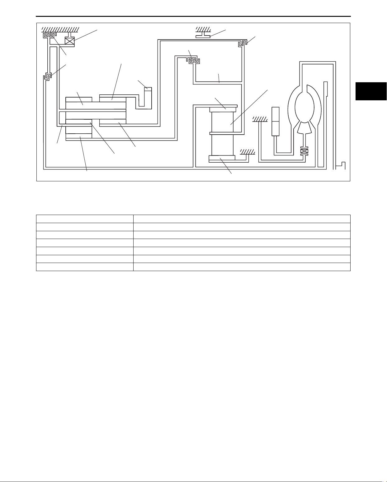
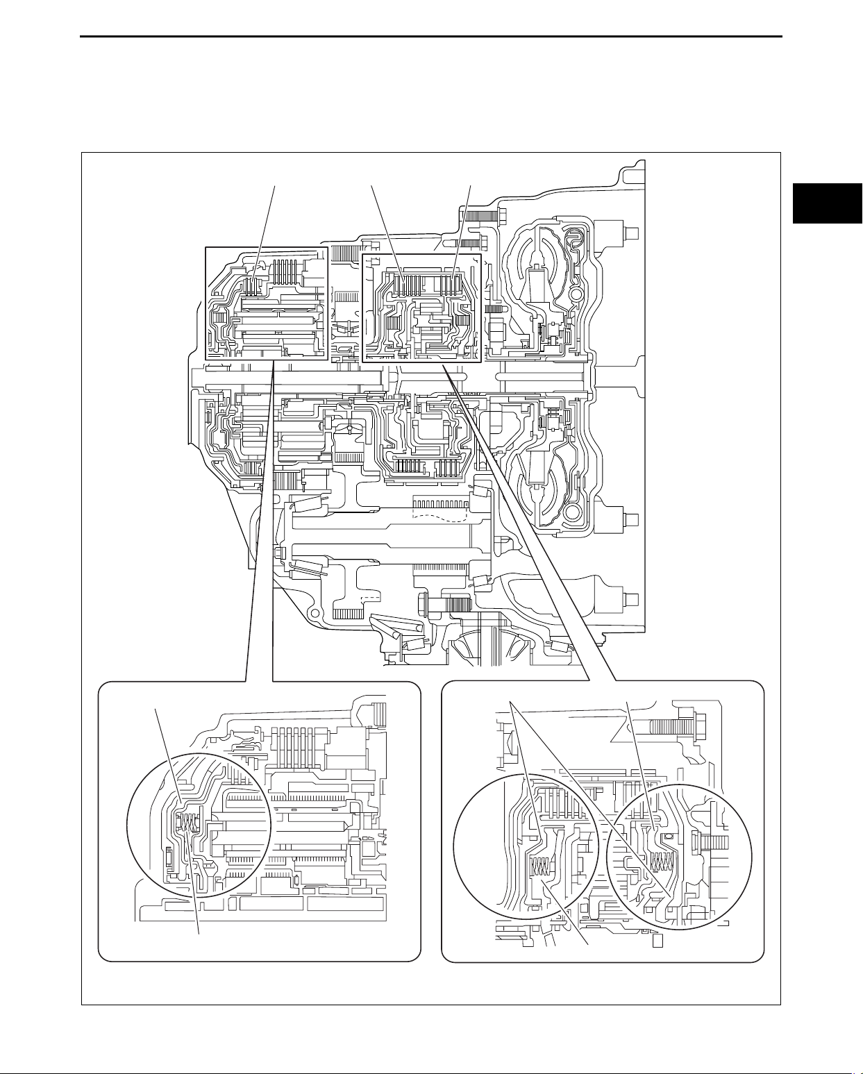
CENTRIFUGAL HYDRAULIC PRESSURE CANCEL CLUTCH OUTLINE
id051700102400
• When the rotation of the clutch rises, centrifugal force operates on the oil inside the clutch, hydraulic pressure
rises, and the clutch is engaged at an earlier timing. Because of this, a difference arises in rotation between the
input shaft and the output shaft, and shift shock may occur. To solve this, an additional chamber has been
provided opposite the piston hydraulic pressure chamber. This causes centrifugal hydraulic pressure to operate
in the opposite direction with the same force as the piston, counteracting that pressure.
C2 CLUTCH
C1 CLUTCH
C3 CLUTCH
05-17
A
B
A : PISTON HYDRAULIC PRESSURE CHAMBER
B : CENTRIFUGAL HYDRAULIC PRESSURE CANCEL CHAMBER
A
B
B
acxuun00000628
05-17–15
Page 26
AUTOMATIC TRANSAXLE
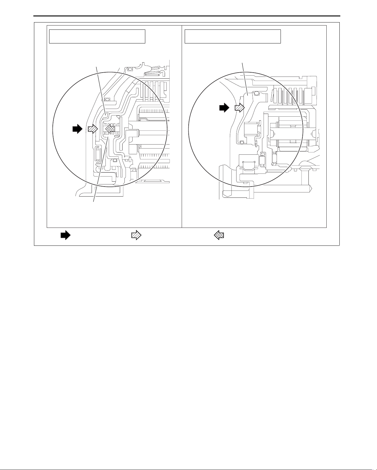
WITH CENTRIFUGAL HYDRAULIC
PRESSURE CANCEL CLUTCH
PISTON HYDRAULIC
PRESSURE CHAMBER
CENTRIFUGAL HYDRAULIC
PRESSURE CANCEL CHAMBER
WITHOUT CENTRIFUGAL HYDRAULIC
PRESSURE CANCEL CLUTCH
PISTON HYDRAULIC
PRESSURE CHAMBER
End Of Sie
NG: TORQUE CONVERTER
PISTON HYDRAULIC
PRESSURE
CENTRIFUGAL HYDRAULIC
PRESSURE
CENTRIFUGAL HYDRAULIC
PRESSURE CANCEL
acxuun00000629
05-17–16
Page 27
AUTOMATIC TRANSAXLE
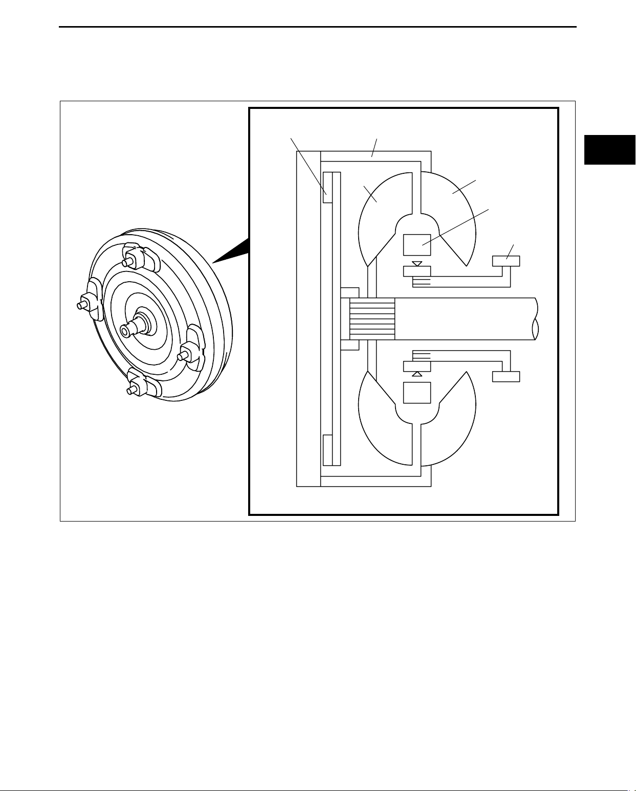
TORQUE CONVERTER OUTLINE
id051700100700
• The torque converter is composed of the converter cover, pump impeller, turbine runner, stator, one-way clutch,
and TCC. The torque converter transmits and amplifies torque by means of the ATF inside it. In addition, the
use of the TCC is intended to improve fuel economy as a direct coupling between the engine and automatic
transaxle.
CONVERTER
TCC PISTON
COVER
TURBINE
RUNNER
PUMP
IMPELLER
STATER
OIL PUMP
INPUT SHAFT
05-17
End Of Sie
acxuun00000605
05-17–17
Page 28

Page 29
SERVICE
Page 30

Page 31

GENERAL INFORMATION
To c o f S C T
GENERAL INFORMATION . . . .00-00
To c o f S C T
00-00 GENERAL INFORMATION
00
SECTION
00-00
HOW TO USE THIS MANUAL . . . . . . . . . 00-00–2
Range of Topics . . . . . . . . . . . . . . . . . . 00-00–2
Service Procedure . . . . . . . . . . . . . . . . 00-00–2
Symbols . . . . . . . . . . . . . . . . . . . . . . . . 00-00–4
Advisory Messages . . . . . . . . . . . . . . . . 00-00–4
UNITS . . . . . . . . . . . . . . . . . . . . . . . . . . . . 00-00–5
Conversion to SI Units (Système
International d'Unités) . . . . . . . . . . . . 00-00–5
Rounding Off. . . . . . . . . . . . . . . . . . . . . 00-00–5
Upper and Lower Limits . . . . . . . . . . . . 00-00–5
FUNDAMENTAL PROCEDURES. . . . . . . 00-00–6
Preparation of Tools and Measuring
Equipment . . . . . . . . . . . . . . . . . . . . . 00-00–6
Special Service Tools . . . . . . . . . . . . . . 00-00–6
Disassembly . . . . . . . . . . . . . . . . . . . . . 00-00–6
End of Toc
WM: GENERAL INFORMATION
Inspection During Removal,
Disassembly. . . . . . . . . . . . . . . . . . . . 00-00–6
Arrangement of Parts . . . . . . . . . . . . . . 00-00–7
Cleaning of Parts . . . . . . . . . . . . . . . . . 00-00–7
Reassembly . . . . . . . . . . . . . . . . . . . . . 00-00–7
Adjustment . . . . . . . . . . . . . . . . . . . . . . 00-00–8
Rubber Parts and Tubing . . . . . . . . . . . 00-00–8
Hose Clamps . . . . . . . . . . . . . . . . . . . . 00-00–8
Torque Formulas . . . . . . . . . . . . . . . . . 00-00–8
Vise . . . . . . . . . . . . . . . . . . . . . . . . . . . 00-00–9
ELECTRICAL SYSTEM. . . . . . . . . . . . . . 00-00–9
Connectors. . . . . . . . . . . . . . . . . . . . . . 00-00–9
SAE STANDARDS. . . . . . . . . . . . . . . . . . 00-00–10
ABBREVIATIONS . . . . . . . . . . . . . . . . . . 00-00–11
00-00–1
Page 32

GENERAL INFORMATION
HOW TO USE THIS MANUAL
id000000800100
Range of Topics
• This manual contains procedures for performing all required service operations. The procedures are divided
into the following five basic operations:
— Removal/Installation
— Disassembly/Assembly
— Replacement
— Inspection
— Adjustment
• Simple operations which can be performed easily just by looking at the vehicle (i.e., removal/installation of
parts, jacking, vehicle lifting, cleaning of parts, and visual inspection) have been omitted.
Service Procedure
Inspection, adjustment
• Inspection and adjustment procedures are
divided into steps. Important points regarding the
location and contents of the procedures are
SHOWS PROCEDURE ORDER
FOR SERVICE
explained in detail and shown in the illustrations.
Fluid Pressure Inspection
1. Assemble the SSTs as shown in the figure.
Tightening torque
39—49 N·m {4.0—5.0 kgf·m, 29—36 ft·lbf}
49 1232 670A
49 H002 671
49 H032 322
Caution
Connect the gauge set from under
the vehicle to prevent contact with
the drive belt and the cooling fan.
SHOWS TIGHTENING
TORQUE
SPECIFICATIONS
acxuuw00000434
Repair procedure
1. Most repair operations begin with an overview illustration. It identifies the components, shows how the parts fit
together, and describes visual part inspection. However, only removal/installation procedures that need to be
performed methodically have written instructions.
2. Expendable parts, tightening torques, and symbols for oil, grease, and sealant are shown in the overview
illustration. In addition, symbols indicating parts requiring the use of special service tools or equivalent are also
shown.
3. Procedure steps are numbered and the part that is the main point of that procedure is shown in the illustration
with the corresponding number. Occasionally, there are important points or additional information concerning a
procedure. Refer to this information when servicing the related part.
00-00–2
Page 33

GENERAL INFORMATION
GREASE
GREASE
Procedure
"Removal/Installation"
Portion
"Inspection After
Installation" Portion
INSTALL THE PARTS BY
PERFORMING STEPS
—
1 3 IN REVERSE ORDER
SHOWS REFERRAL
NOTES FOR SERVICE
SHOWS SERVICE
ITEM (S)
LOWER TRAILING LINK, UPPER TRAILING LINK REMOVAL/INSTALLATION
1
1. Jack up the rear of the vehicle and support it with safety stands.
2. Remove the undercover. (See 01-10-4 Undercover Removal)
3. Remove in the order indicated in the table.
4. Install in the reverse order of removal.
5. Inspect the rear wheel alignment and adjust it if necessary.
2
SHOWS PROCEDURE ORDER
FOR SERVICE
44—60 {4.4—6.2, 32—44}
11
10
SST
9
SST
12
43—56 {4.3—5.8, 32—41}
8
R
7
SHOWS TIGHTENING
TORQUE
SPECIFICATIONS
SST
3
5
6
SST
4
94—116 {9.5—11.9, 69—86}
Split pin
1
Nut
2
Lower trailing link ball joint
3
(See 02-14-5 Lower Trailing Link Ball Joint Removal Note)
Bolt
4
Lower trailing link
5
Dust boot (lower trailing link)
6
GREASE
R
Split pin
7
8Nut
9 Upper trailing link ball joint
(See 02-14-5 Upper Trailing Link Ball Joint Removal Note)
10
Nut
Upper trailing link
11
Dust boot (upper trailing link)
12
118—156 {12.0—16.0, 87—115}
2
1
INDICATES RELEVANT
REFERENCES THAT NEED
TO BE FOLLOWED DURING
INSTALLATION
SHOWS SPECIAL
SERVICE TOOL (SST)
FOR SERVICE OPERATION
GREASE
R
SHOWS APPLICATION
POINTS OF GREASE, ETC.
SHOWS EXPENDABLE PARTS
SHOWS DETAILS
R
N·m {kgf·m, ft·lbf}
00-00
SHOWS TIGHTENING
TORQUE UNITS
Lower Trailing Link Ball Joint, Upper Trailing Link
Ball Joint Removal Note
Remove the ball joint using the SSTs.
SHOWS REFERRAL
NOTES FOR
SERVICE
SHOWS SPECIAL
SERVICE TOOL (SST)
NO.
KNUCKLE
49 T028 304
49 T028 305
UPPER TRAILING LINK
LOWER TRAILING LINK
49 T028 303
acxuuw00000435
00-00–3
Page 34

GENERAL INFORMATION
TF
GREASE
Symbols
• There are eight symbols indicating oil, grease, fluids, sealant, and the use of SST or equivalent. These symbols
show application points or use of these materials during service.
Symbol Meaning Kind
OIL
BRAKE
FLUID
AATF
GREASE
SEALANT
P
Apply oil
Apply brake fluid
Apply automatic
transaxle/
transmission fluid
Apply grease
Apply sealant
Apply petroleum
jelly
New appropriate
engine oil or gear
oil
New appropriate
brake fluid
New appropriate
automatic
transaxle/
transmission fluid
Appropriate
grease
Appropriate
sealant
Appropriate
petroleum jelly
R
SST
Replace part
Use SST or
equivalent
O-ring, gasket,
etc.
Appropriate tools
Advisory Messages
• You will find several Warnings, Cautions, Notes, Specifications and Upper and Lower Limits in this
manual.
Warning
• A Warning indicates a situation in which serious injury or death could result if the warning is ignored.
Caution
• A Caution indicates a situation in which damage to the vehicle or parts could result if the caution is ignored.
Note
• A Note provides added information that will help you to complete a particular procedure.
Specification
• The values indicate the allowable range when performing inspections or adjustments.
Upper and lower limits
• The values indicate the upper and lower limits that must not be exceeded when performing inspections or
adjustments.
End Of Sie
NG: GENERAL INFORMATION
00-00–4
Page 35

GENERAL INFORMATION
UNITS
Electrical current A (ampere)
Electric power W (watt)
Electric resistance ohm
Electric voltage V (volt)
Length
Negative pressure
Positive pressure
Number of
revolutions
To r qu e
Volum e
Weight
mm (millimeter)
in (inch)
kPa (kilo pascal)
mmHg (millimeters of mercury)
inHg (inches of mercury)
kPa (kilo pascal)
2
(kilogram force per square
kgf/cm
centimeter)
psi (pounds per square inch)
rpm (revolutions per minute)
N·m (Newton meter)
kgf·m (kilogram force meter)
kgf·cm (kilogram force centimeter)
ft·lbf (foot pound force)
in·lbf (inch pound force)
L (liter)
US qt (U.S. quart)
Imp qt (Imperial quart)
ml (milliliter)
cc (cubic centimeter)
cu in (cubic inch)
fl oz (fluid ounce)
g (gram)
oz (ounce)
id000000100400
00-00
Conversion to SI Units (Système International d'Unités)
• All numerical values in this manual are based on SI units. Numbers shown in conventional units are converted
from these values.
Rounding Off
• Converted values are rounded off to the same number of places as the SI unit value. For example, if the SI unit
value is 17.2 and the value after conversion is 37.84, the converted value will be rounded off to 37.8.
Upper and Lower Limits
• When the data indicates upper and lower limits, the converted values are rounded down if the SI unit value is
an upper limit, and rounded up if the SI unit value is a lower limit. Therefore, converted values for the same SI
unit value may differ after conversion. For example, consider 2.7 kgf/cm
210— 260 kPa {2.1— 2.7 kgf/cm
270— 310 kPa {2.7— 3.2 kgf/cm
• The actual converted values for 2.7 kgf/cm
2
, 30— 38 psi}
2
, 39— 45 psi}
2
are 265 kPa and 38.4 psi. In the first specification, 2.7 is used as
2
in the following specifications:
an upper limit, so the converted values are rounded down to 260 and 38. In the second specification, 2.7 is
used as a lower limit, so the converted values are rounded up to 270 and 39.
End Of Sie
WM: GENERAL INFORMATION
00-00–5
Page 36

GENERAL INFORMATION
FUNDAMENTAL PROCEDURES
Preparation of Tools and Measuring Equipment
• Be sure that all necessary tools and measuring
equipment are available before starting any work.
Special Service Tools
• Use special service tools or the equivalent when
they are required.
id000000810000
acxuuw00000006
49 SE01 310
Disassembly
• If the disassembly procedure is complex,
requiring many parts to be disassembled, all parts
should be marked in a place that will not affect
their performance or external appearance, and
identified so that reassembly can be performed
easily and efficiently.
Inspection During Removal, Disassembly
• When removed, each part should be carefully
inspected for malfunction, deformation, damage
and other problems.
acxuuw00000007
acxuuw00000010
00-00–6
acxuuw00000011
Page 37

GENERAL INFORMATION
Arrangement of Parts
• All disassembled parts should be carefully
arranged for reassembly.
• Be sure to separate or otherwise identify the parts
to be replaced from those that will be reused.
Cleaning of Parts
• All parts to be reused should be carefully and
thoroughly cleaned in the appropriate method.
Warning
• Using compressed air can cause dirt and
other particles to fly out causing injury to
the eyes. Wear protective eye wear
whenever using compressed air.
00-00
acxuuw00000012
Reassembly
• Standard values, such as torques and certain
adjustments, must be strictly observed in the
reassembly of all parts.
• If removed, these parts should be replaced with
new ones:
— Oil seals
— Gaskets
— O-rings
— Lock washers
— Cotter pins
— Nylon nuts
• Depending on location:
— Sealant and gaskets, or both, should be
applied to specified locations. When sealant
is applied, parts should be installed before
sealant hardens to prevent leakage.
— Oil should be applied to the moving
components of parts.
— Specified oil or grease should be applied at
the prescribed locations (such as oil seals)
before reassembly.
acxuuw00000013
acxuuw00000014
acxuuw00000326
00-00–7
Page 38

GENERAL INFORMATION
Adjustment
• Use suitable gauges and testers when making
adjustments.
Rubber Parts and Tubing
• Prevent gasoline or oil from getting on rubber
parts or tubing.
acxuuw00000016
Hose Clamps
• When reinstalling, position the hose clamp in the
original location on the hose and squeeze the
clamp lightly with large pliers to ensure a good fit.
Torque Formulas
• When using a torque wrench-SST or equivalent
combination, the specified torque must be
recalculated due to the extra length that the SST
or equivalent adds to the torque wrench.
Recalculate the torque by using the following
formulas. Choose the formula that applies to you.
Torque Unit Formula
N·m N·m × [L/(L+A)]
kgf·m kgf·m × [L/(L+A)]
kgf·cm kgf·cm × [L/(L+A)]
ft·lbf ft·lbf × [L/(L+A)]
in·lbf in·lbf × [L/(L+A)]
acxuuw00000017
acxuuw00000018
SST
A
L
3
2
1
0
1
2
3
acxuuw00000019
A : The length of the SST past the torque wrench drive.
L : The length of the torque wrench.
00-00–8
Page 39

GENERAL INFORMATION
Vise
• When using a vise, put protective plates in the
jaws of the vise to prevent damage to parts.
End Of Sie
ELECTRICAL SYSTEM
Connectors
Disconnecting connectors
• When disconnecting a connector, grasp the
connectors, not the wires.
PROTECTIVE PLATES
GOOD
00-00
acxuuw00000020
id000000800400
NO GOOD
• Connectors can be disconnected by pressing or
pulling the lock lever as shown.
Locking connector
• When locking connectors, listen for a click
indicating they are securely locked.
acxuuw00000454
acxuuw00000455
acxuuw00000456
00-00–9
Page 40

GENERAL INFORMATION
Inspection
Caution
• To prevent damage to the terminal, wrap a thin wire around the tester probe before inserting into
terminal.
• When a tester is used to inspect for continuity or
measuring voltage, insert the tester probe from
the wiring harness side.
• Inspect the terminals of waterproof connectors
from the connector side since they cannot be
accessed from the wiring harness side.
End Of Sie
GOOD
GOOD NO GOOD
NO GOOD
acxuuw00000457
acxuuw00000458
SAE STANDARDS
id000000800900
• In accordance with new regulations, SAE (Society of Automotive Engineers) standard names and abbreviations
are now used in this manual. The table below lists the names and abbreviations that have been used in Mazda
manuals up to now and their SAE equivalents.
SAE Standard
Abbreviation Name Abbreviation Name
AP Accelerator Pedal MAP Manifold Absolute Pressure
APP Accelerator Pedal Position MAF sensor Mass Air Flow Sensor
ACL Air Cleaner MFL Multiport Fuel Injection
A/C Air Conditioning OBD On-board Diagnostic System
BARO Barometric Pressure OL Open Loop
B+ Battery Positive Voltage OC Oxidation Catalytic Converter
CMP sensor Camshaft Position Sensor O2S Oxygen sensor
CAC Charge Air Cooler PNP Park/Neutral Position
CLS Closed Loop System PSP Power Steering Pressure
CTP Closed Throttle Position PCM Powertrain Control Module #3
CPP Clutch Pedal Position
CIS Continuous Fuel Injection System
CKP sensor Crankshaft Position Sensor
DLC Data Link Connector
DTM Diagnostic Test Mode #1
DTC Diagnostic Test Code(s) SAPV Secondary Air Pulse Valve
DI Distributor Ignition
DLI Distributorless Ignition
EI Electronic Ignition #2 3GR Third Gear
ECT Engine Coolant Temperature TWC Three Way Catalytic Converter
EM Engine Modification TB Throttle Body
EVAP Evaporative Emission TP sensor Throttle Position Sensor
Remark
PAIR Pulsed Secondary Air Injection
AIR Secondary Air Injection
SFI
SAE Standard
Sequential Multiport Fuel
Injection
Remark
Pulsed
injection
Injection
with air
pump
00-00–10
Page 41

GENERAL INFORMATION
SAE Standard
Abbreviation Name Abbreviation Name
EGR Exhaust Gas Recirculation TCC Torque Converter Clutch
FC Fan Control
FF Flexible Fuel
4GR Fourth Gear TR Transmission (Transaxle) Range
GEN Generator TC Turbocharger
GND Ground VSS Vehicle Speed Sensor
HO2S Heated Oxygen Sensor
IAC Idle Air Control
IAT Intake Air Temperature
KS Knock Sensor WOP Wide Open Throttle
MIL Malfunction Indicator Lamp
Remark
With
heater
TCM
VR Voltage Regulator
VAF sensor Volume Air Flow Sensor
WU-TWC
SAE Standard
Transmission (Transaxle) Control
Module
Warm Up Three Way Catalytic
Converter
#1: Diagnostic trouble codes depend on the diagnostic test mode.
#2: Controlled by the PCM
#3: Device that controls engine and powertrain
#4: Directly connected to exhaust manifold
End Of Sie
ABBREVIATIONS
ATF Automatic Transaxle Fluid
LH Left Hand
RH Right Hand
SST Special Service Tool
TFT Transaxle Fluid Temperature
2WD 2 Wheel Drive
Remark
00-00
#4
id000000801000
End Of Sie
00-00–11
Page 42

Page 43

DRIVELINE/AXLE
To c o f S C T
TRANSFER . . . . . . . . . . . . . . . . 03-16
TECHNICAL DATA . . . . . . . . . .03-50
To c o f S C T
03-16 TRANSFER
03
SECTION
03-16
SERVICE TOOLS . . . . . . . . . . . 03-60
TRANSFER CLEANING. . . . . . . . . . . . . . 03-16–1
Cleaning Precautions . . . . . . . . . . . . . . 03-16–1
TRANSFER DISASSEMBLY . . . . . . . . . . 03-16–1
Before Service Precautions. . . . . . . . . . 03-16–1
Transfer Component Disassembly . . . . 03-16–2
Transfer Component Disassembling
Procedure . . . . . . . . . . . . . . . . . . . . . . 03-16–3
Drive Gear Case Component
Disassembly . . . . . . . . . . . . . . . . . . . . 03-16–4
Drive Gear Case Component
Disassembly Procedure . . . . . . . . . . . 03-16–5
Front Carrier Component
Disassembly . . . . . . . . . . . . . . . . . . . . 03-16–9
Front Carrier Component Disassembling
Procedure . . . . . . . . . . . . . . . . . . . . . 03-16–10
TRANSFER ASSEMBLY . . . . . . . . . . . . . 03-16–13
Before Service Precautions . . . . . . . . . 03-16–13
Drive Gear Case Component
Assembly. . . . . . . . . . . . . . . . . . . . . . 03-16–14
Drive Gear Case Component Assembly
Procedure . . . . . . . . . . . . . . . . . . . . . 03-16–15
Front Carrier Component Assembly. . . 03-16–21
Front Carrier Component Assembly
Procedure . . . . . . . . . . . . . . . . . . . . . 03-16–22
Transfer Component Assembly . . . . . . 03-16–28
Transfer Component Assembly
Procedure . . . . . . . . . . . . . . . . . . . . . 03-16–29
End of Toc
AT: TRANSFER
TRANSFER CLEANING
Cleaning Precautions
1. Clean the surface of the transfer using steam and cleaning fluids when disassembly.
Warning
• Always wear safety glasses when using compressed air since the foreign material could be blown
by the compression air and damage your eyes.
2. Clean removed components with cleaning fluids and use compressed air to blow off the oil. Clean the oil holes
and passages with compressed air.
id031600500100
End Of Sie
TRANSFER DISASSEMBLY
Before Service Precautions
• To prevent foreign material from entering the transfer, perform disassembly and servicing in a clean, dust-free
environment.
• Inspect the each part while disassembling.
id031600500200
Warning
• The engine stand is equipped with a self-lock mechanism. However, if the transfer is tilted, the
self-lock mechanism could become inoperative. This could cause the transfer to rotate
accidentally, resulting in injury. Therefore, make sure that the transfer is not tilted when it is on the
engine stand. When turning the transfer, grasp the rotation handle firmly.
03-16–1
Page 44

Transfer Component Disassembly
R
TRANSFER
3
R
5
4
R
2
R
.
1 Drain plug
2 Oil level plug
3 Oil cooler
03-16–2
1
bawuua00000167
4 Drive gear case component
5 Front carrier component
Page 45

Transfer Component Disassembling Procedure
1. Assemble the SSTs.
2. Install the transfer component to the SSTs.
3. Remove the oil cooler.
4. Remove the drive gear case component.
TRANSFER
49 0107 680A
03-16
49 M005 561
bawuua00000168
49 M005 561
49 0107 680A
bawuua00000169
03-16–3
Page 46

Drive Gear Case Component Disassembly
TRANSFER
RH
5
3
4
6
8
SST
9
SST
7
1
R
10
R
SST
11
12
SST
R
15
LH
2
.
1 Oil seal (RH outer)
2 Drive gear shaft
3 Bearing cap
4 Adjustment shim
5 Spacer
6 Drive gear component
7 Bearing outer race (LH)
8 Bearing outer race (RH)
SST
SST
R
14
R
13
R
9 Bearing (RH)
10 Bearing (LH)
11 Drive gear
12 Oil seal (RH inner)
13 Oil seal (LH outer)
14 Oil seal (LH inner)
15 Baffle plate
16 Drive gear case
16
bawuua00000170
03-16–4
Page 47

TRANSFER
Drive Gear Case Component Disassembly Procedure
1. Install the drive gear case component to the SST.
2. Tap the drive gear shaft using a suitable rod and
hammer.
49 M005 561
03-16
bawuua00000171
3. Take out the drive gear shaft from the drive gear
case.
4. Make alignment marks on the bearing cap and
drive gear case.
5. Remove the bearing cap.
bawuua00000172
bawuua00000173
ALIGNMENT MARK
bawuua00000174
03-16–5
Page 48

6. Insert a flathead screwdriver into spacer notch
and remove the adjustment shim.
Caution
• Place a rag on the case to protect it from
damage.
TRANSFER
bawuua00000175
7. Remove the spacer.
8. Remove the drive gear component.
9. Using the SST, remove the oil seal (LH outer).
RAG
bawuua00000176
bawuua00000177
bawuua00000178
03-16–6
49 0839 425C
49 W032 201
bawuua00000179
Page 49

TRANSFER
10. Using the SST, remove the oil seal (LH inner).
11. Using a suitable rod and hammer, remove the oil
seal (RH outer).
12. Using the SST, remove the oil seal (RH inner).
49 0839 425C
03-16
49 W032 201
bawuua00000179
bawuua00000180
13. Using the SST, remove the bearing outer race
(LH).
(1) Install the SSTs (49 W032 202, 49 S019 005).
49 W032 201
49 0839 425C
bawuua00000181
BEARING RACE
bawuua00000182
49 W032 202
49 S019 005
bawuua00000183
03-16–7
Page 50

(2) Connect the SST (49 T032 316, 49 T032 317)
to the SSTs (49 W032 202, 49 S019 005).
14. Remove the baffle plate.
15. Using the SST, remove the bearing (RH).
TRANSFER
49 W032 202
49 T032 316
49 T032 317
49 S019 005
bawuua00000184
bawuua00000185
16. Using a flathead screwdriver, deform the bearing
roller guide (LH) and remove it.
17. Using the SST, remove the bearing inner race
(LH).
49 0839 425C
bawuua00000186
bawuua00000187
49 0636 145
03-16–8
bawuua00000188
Page 51

Front Carrier Component Disassembly
TRANSFER
R
5
17
SST
16
15
R
SST
R
SST
21
22
23
19
10
.
1 Oil pipe
2 Oil strainer
3 Side cover
4 Ring gear lockbolt
5 Oil pump
6 Oil pump shaft
7 Bearing cap
8 Ring gear component
9 Adjustment shim
10 Spacer
11 Bearing outer race (side)
12 Bearing (side)
13 Ring gear
6
03-16
20
25
24
1
SST
LEFT—HAND SCREW
4
A
R
18
R
R
3
2
9
11
12
SST
SST
A
7
14
SST
13
SST
12
11
8
SST
14 Ring gear shaft
15 Locknut
16 Washer
17 Companion flange
18 Oil seal
19 Drive pinion gear
20 Bearing (rear)
21 Distance piece
22 Bearing (front)
23 Spacer
24 Bearing outer race (front)
25 Bearing outer race (rear)
9
bawuua00000189
03-16–9
Page 52

TRANSFER
Front Carrier Component Disassembling Procedure
1. Install the front carrier component to the SST.
2. Remove the oil strainer.
3. Remove the oil pipe.
4. Remove the side cover.
5. Remove the oil pump by turning it using pliers as
shown in the figure.
• If the oil pump shaft remains in the gear shaft
side, remove the oil pump shaft.
49 M005 561
bawuua00000190
6. Make alignment marks on the bearing caps and
front carrier.
7. Remove the bearing caps.
8. Using a suitable wrench, secure the ring gear
shaft, and remove the ring gear lockbolt.
bawuua00000191
MARK
bawuua00000192
bawuua00000193
03-16–10
Page 53

TRANSFER
9. Using the SST, secure the companion flange, and
remove the locknut and washer.
10. Using the SST, remove the companion flange.
11. Using the SSTs, remove the ring gear
component.
12. Remove the adjustment shims and spacer.
49 S120 710
03-16
bawuua00000546
49 0839 425C
bawuua00000536
13. Install an appropriate nut to the drive pinion to
prevent the thread from being damaged.
14. Lightly tap the drive pinion using a copper
hammer and remove the drive pinion gear.
49 T032 316
49 T032 317
49 L027 004
bawuua00000196
bawuua00000537
03-16–11
Page 54

TRANSFER
15. Using a flathead screwdriver, remove the oil seal.
16. Remove the bearing (rear) and distance piece.
17. Using the SST, remove the bearing (front).
18. Remove the spacer.
19. Attach the brass stick to the notch, tap the race
end lightly and evenly, then remove the bearing
outer races.
bawuua00000198
49 H027 002
bawuua00000199
20. Using the SSTs, remove the bearing (side)
(opposite ring gear side).
bawuua00000200
bawuua00000201
49 0839 425C
(ATTACHMENT
39.5 mm {1.56 in})
49 0710 520
bawuua00000202
03-16–12
Page 55

TRANSFER
21. Using a SST, remove the bearing (side) (ring gear
side) together with ring gear.
Substitution SST
• 49 T032 302
Outer diameter: 25— 30 mm {0.99— 1.18 in}
Plate thickness: 1 mm {0.04 in} or more
End Of Sie
TRANSFER ASSEMBLY
Before Service Precautions
• Assemble with bare hands or using vinyl gloves. To prevent foreign material from entering the transfer, do not
use cotton work gloves or a rag.
• Apply sufficient gear oil to the sliding surfaces and O-rings, and be careful not to damage when assembling.
• Replace the transfer with a new one if the case alignment surface is damaged. Be careful not to damage it
since it may cause oil leakage.
• When installing silicone sealant, clean off the old sealant adhering to the sealing area and clean the sealing
area with cleaning fluids.
• After installing a seal, leave the parts alone for 2 h or more. Do not add oil or operate the vehicle during this
time.
49 T032 302
bawuua00000203
id031600500300
03-16
Warning
• The engine stand is equipped with a self-lock mechanism. However, if the transfer is tilted, the
self-lock mechanism could become inoperative. This could cause the transfer to rotate
accidentally, resulting in injury. Therefore, make sure that the transfer is not tilted when it is on the
engine stand. When turning the transfer, grasp the rotation handle firmly.
03-16–13
Page 56

Drive Gear Case Component Assembly
37—51 N·m
{3.8—5.2 kgf·m, 27.3—37.6 ft·lbf}
TRANSFER
RH
8
10
9
7
4
SST
3
5
6.9—9.8 N·m
1
SST
2
15
{70—99 kgf·cm, 61—86 in·lbf}
6
R
SST
11
R
SST
LH
14
.
1 Drive gear
2 Bearing (LH)
3 Bearing (RH)
4 Bearing outer race (RH)
5 Bearing outer race (LH)
6 Oil seal (RH inner)
7 Drive gear component
8 Spacer
R
SST
RSST
13
R
12
16
bawuua00000204
9 Adjustment shim
10 Bearing cap
11 Oil seal (RH outer)
12 Oil seal (LH inner)
13 Oil seal (LH outer)
14 Drive gear shaft
15 Baffle plate
16 Drive gear case
03-16–14
Page 57

TRANSFER
Drive Gear Case Component Assembly Procedure
1. Install the drive gear case to the SST.
2. Install the baffle plate.
Tightening torque
6.9— 9.8 N·m {70— 99 kgf·cm, 61— 86 in·lbf}
49 M005 561
03-16
bawuua00000205
3. Using a press, assemble the bearing (RH).
Substitution SST
• 49 H028 202
Outer diameter: 58— 61 mm {2.29— 2.40 in}
Inner diameter: 56 mm {2.20 in} or more
Plate thickness: 1 mm {0.04 in} or more
4. Using a press, assemble the bearing (LH).
Substitution SST
• 49 H028 202
Outer diameter: 58— 61 mm {2.29— 2.40 in}
Inner diameter: 56 mm {2.20 in} or more
Plate thickness: 1 mm {0.04 in} or more
5. Temporarily assemble the bearing outer race
(RH) and spacer to the drive gear.
bawuua00000206
49 H028 202
bawuua00000207
49 H028 202
bawuua00000208
03-16–15
Page 58

TRANSFER
6. Place the drive gear component on the surface
plate as shown in the figure, and measure the
height using a vernier caliper or height gauge.
This is dimension A.
7. Measure the width of the drive gear installation
area in the drive gear case. This is dimension B.
8. The maximum and minimum thickness C of the
adjustment shim can be expressed by the
following formula:
C = B - A - (0.01— 0.03 mm {0.00039—
0.00118 in})
9. If the thickness of the installed adjustment shim is
within the C range, use the shim as it is.
10. If the thickness of the installed adjustment shim is
not within the C range, select the appropriate
adjustment shim from the table below and use it.
A
bawuua00000209
B
Adjustment shim
Identification mark Thickness (mm {in}) Identification mark Thickness (mm {in})
350 3.50 {0.1378} 420 4.20 {0.1654}
355 3.55 {0.1398} 425 4.25 {0.1673}
360 3.60 {0.1417} 430 4.30 {0.1693}
365 3.65 {0.1437} 435 4.35 {0.1713}
370 3.70 {0.1457} 440 4.40 {0.1732}
375 3.75 {0.1476} 445 4.45 {0. 1752}
380 3.80 {0.1496} 450 4.50 {0.1772}
385 3.85 {0.1516} 455 4.55 {0.1791}
390 3.90 {0.1535} 460 4.60 {0. 1811}
395 3.95 {0.1555} - 400 4.00 {0.1575} - 405 4.05 {0.1594} - 410 4.10 {0.1614} - 415 4.15 {0.1634} - -
11. Using the plastic hammer, install the bearing
outer race (LH).
bawuua00000210
03-16–16
bawuua00000211
Page 59

TRANSFER
12. Install the drive gear component.
13. Install the spacer with its notch facing the bearing,
and also facing upward, as shown in the figure.
14. Using a plastic hammer, assemble the adjustment
shim.
03-16
bawuua00000212
bawuua00000213
15. Align the bearing cap alignment marks, assemble
the bearing cap.
Tightening torque
37— 51 N·m {3.8— 5.2 kgf·m, 27.3— 37.6
ft·lbf}
16. Assemble the SST to the drive gear shaft, and
hand-tighten the nut.
SST tightening torque
2.1 N·m {21 kgf·cm, 19 in·lbf}
bawuua00000214
ALIGNMENT MARK
bawuua00000215
49 L011 201
bawuua00000216
03-16–17
Page 60

TRANSFER
17. Install the drive gear shaft with the SST
assembled and verify that the preload is within the
specification using the torque wrench as shown in
the figure.
Standard drive gear bearing preload
0.6— 2.1 N·m {6.2— 21.4 kgf·cm, 5.4— 18.5
in·lbf}
• If the drive gear rotational torque is not within
the specification, adjust it by selecting the
proper spacer.
18. Remove the drive gear shaft.
19. Using a SSTs, install the oil seals.
Note
• Mark the press-in depth of each oil seal to the SST and press fit oil seals to the specified position.
LH inner
Substitution SST
• 49 S019 006
Outer diameter: 61— 66 mm {2.41— 2.59 in}
Plate thickness: 2 mm {0.08 in} or more
49 G030 797
49 S019 006
bawuua00000217
15.7—17.3
{0.62—0.68}
mm {in}
bawuua00000218
03-16–18
Page 61

LH outer
RH inner
Substitution SST
• 49 B025 001
Outer diameter: 57— 64 mm {2.25— 2.51 in}
Plate thickness: 2 mm {0.08 in} or more
TRANSFER
49 G030 797
49 L019 301
03-16
OIL SEAL
5.0—6.0
{0.20—0.23}
mm {in}
bawuua00000219
49 G030 797
49 B025 001
18.7—20.3
{0.74—0.79}
mm {in}
bawuua00000220
03-16–19
Page 62

TRANSFER
RH outer
Substitution SST
• 49 T034 201A
Outer diameter: 59— 64 mm {2.33— 2.51 in}
Inner diameter: 55 mm {2.17 in} or more
Length: 5 mm {0.20 in} or more
Plate thickness: 2 mm {0.08 in} or more
20. Install the C-ring to the drive gear shaft and insert
the drive gear shaft until it is secured by the Cring.
49 T034 201A
-0.8—0.8
{-0.03—0.03}
mm {in}
bawuua00000221
Caution
• Be careful not to damage the oil seal
when installing the drive gear shaft.
21. Pull the drive gear shaft by hand and verify that
the drive gear shaft is secured by the C-ring at the
specified position.
bawuua00000222
bawuua00000223
03-16–20
Page 63

Front Carrier Component Assembly
GREASE
TRANSFER
R
21
127—284
{13.0—28.9, 93.7—209.4}
SST
11
R
10
GREASE
9
OIL
03-16
R
SST
5
4
3
7
SST
17
63—93 {6.5—9.4, 46.4—68.5}
.
1 Bearing outer race (rear)
2 Bearing outer race (front)
3 Spacer
4 Bearing (front)
5 Distance piece
6 Bearing (rear)
7 Drive pinion gear
8 Oil seal
9 Companion flange
10 Washer
11 Locknut
12 Ring gear shaft
13 Ring gear
16
20
6
SST
1
SST
2
25
SST
R
LEFT—HAND SCREW
22
A
150—200 {15.3—20.3, 110.7—147.4}
SST
R
8
R
23
6.9—9.8 N·m
24
{70—100 kgf·cm, 61—86 in·lbf}
15
R
14
SST
12
A
19
SST
13
SST
R
14
15
18
16
N·m {kgf·m, ft·lbf}
bawuua00000224
14 Bearing (side)
15 Bearing outer race (side)
16 Adjustment shim
17 Spacer
18 Ring gear component
19 Bearing cap
20 Oil pump shaft
21 Oil pump
22 Ring gear lockbolt
23 Side cover
24 Oil strainer
25 Oil pipe
03-16–21
Page 64

TRANSFER
Front Carrier Component Assembly Procedure
1. Using a press, assemble the opposite ring gear
side bearing (side) to the ring gear shaft.
Substitution SST
• 49 G033 105 (A)
Outer diameter: 25 mm {0.99 in} or more
• 49 G033 105 (B)
Outer diameter: 34— 40 mm {1.34— 1.57 in}
Plate thickness: 1 mm {0.04 in} or more
2. Using a press, assemble the ring gear to the ring
gear shaft
Substitution SST
• 49 G033 105
Outer diameter: 15— 30 mm {0.60— 1.18 in}
(A)
49 G033 105
(B)
bawuua00000225
49 G033 105
3. Using a press, assemble the ring gear side
bearing (side).
Substitution SST
• 49 G033 105 (A)
Outer diameter: 15— 30 mm {0.60— 1.18 in}
• 49 G033 105 (B)
Outer diameter: 34— 40 mm {1.34— 1.57 in}
Plate thickness: 1 mm {0.04 in} or more
4. Temporarily assemble the bearing outer races
(side).
5. Place the ring gear component on the surface
plate as shown in the figure, and measure the
height using a vernier caliper or height gauge.
This is dimension A.
49 G033 105
A
bawuua00000226
(A)
(B)
bawuua00000227
bawuua00000228
03-16–22
Page 65

TRANSFER
6. Measure the width of the front carrier ring gear
installation area with the spacer installed. This is
dimension B.
7. The maximum and minimum total thickness C of
the adjustment shims on both sides can be
expressed by the following formula:
B
SPACER
C = B - A - (0.01— 0.03 mm {0.00039— 0.00118
in})
8. If the total thickness of the installed adjustment
shims is within the C range, use the shims as they
are.
9. If the total thickness of the installed adjustment
shims is not within the C range, select the appropriate number of adjustment shims from the table below and
use them.
Adjustment shim
Identification mark Thickness (mm {in}) Identification mark Thickness (mm {in})
350 3.50 {0.1378} 410 4.10 {0.1614}
355 3.55 {0.1398} 415 4.15 {0.1634}
360 3.60 {0.1417} 420 4.20 {0.1654}
365 3.65 {0.1437} 425 4.25 {0.1673}
370 3.70 {0.1457} 430 4.30 {0.1693}
375 3.75 {0.1476} 435 4.35 {0.1713}
380 3.80 {0.1496} 440 4.40 {0.1732}
385 3.85 {0.1516} 445 4.45 {0.1752}
390 3.90 {0.1535} 450 4.50 {0.1772}
395 3.95 {0.1555} 455 4.55 {0.1791}
400 4.00 {0.1574} 460 4.60 {0.1811}
405 4.05 {0.1594} - -
Note
• When reusing adjustment shims, do not mix up the left and right shims.
• Do not mix up the left and right side bearing races and spacers.
03-16
bawuua00000229
10. Install the front carrier to the SST.
11. Install the adjustment shim chosen for the front
carrier ring gear side and spacer on opposite
side.
12. Assemble the ring gear component to the front
carrier.
13. Using the plastic hammer, assemble the selected
adjustment shim in between the spacer and
bearing race as shown in the figure.
49 M005 561
bawuua00000230
bawuua00000231
03-16–23
Page 66

TRANSFER
14. Align the alignment marks of the bearing caps,
assemble the bearing caps, and tighten the bolts
temporarily.
Caution
• Locking compound is applied to a new
ring gear lockbolt. Reuse the old ring
gear lock bolt when inspecting the
preload.
15. Install the ring gear lockbolt and inspect the ring
gear bearing preload.
Standard ring gear bearing preload
0.6— 2.1 N·m {6.2— 21.4 kgf·cm, 5.4— 18.5 in·lbf}
• If the rotational torque is not within the specification, select the suitable adjustment shim and reinstall so
that the rotational torque is within the specification.
16. Follow the disassembling procedure in Step 11 to remove the ring gear component.
Note
• Identify the left and right side of the adjustment shim for reinstallation.
17. Using the SSTs, assemble the bearing outer
races.
Substitution SST
49 F027 003
• 49 F027 005
Outer diameter: 61— 61.8 mm {2.41— 2.43
in}
Plate thickness: 1 mm {0.04 in} or more
• 49 F027 007
Outer diameter: 70— 71.8 mm {2.76— 2.82
in}
Plate thickness: 1 mm {0.04 in} or more
49 F027 005
18. Using the SSTs, adjust the drive pinion height as
follows:
(1) Install the SSTs to the removed spacer and
bearing.
(2) Assemble the spacer, bearing and SSTs.
Using an O-ring, secure the SST.
(3) Assemble the bearing, SSTs, washer, and
nut.
(4) Tighten the nut to the SST to where it can still
be rotated by hand.
49 H025 003A
MARK
49 F027 003
49 8531 565
bawuua00000232
49 F027 007
bawuua00000233
(5) Place the SSTs on the plate surface and set
the dial gauge to “0”.
03-16–24
bawuua00000234
49 0727 570
49 8531 555
49 0305 555
bawuua00000235
Page 67

TRANSFER
(6) Position the SST (49 0727 570) on the driver
pinion model.
(7) Attach the dial gauge head to where the
carrier bearing outer race (side) is installed
and measure the lowest position. Also,
measure the value of where the side bearing
outer race (side) is installed on the opposite
side.
(8) Measure the average value between the
values of both sides measured in Step 7. This
value is the spacer thickness which
determines the pinion height.
Pinion height error factor within allowance
limit
± 0.032 mm {± 0.00126 in}
Spacer
Identification mark Thickness (mm {in}) Identification mark Thickness (mm {in})
08 3.08 {0.1213} 29 3.29 {0.1295}
09 3.095 {0.1219} 30 3.305 {0.1301}
11 3.11 {0.1224} 32 3.32 {0.1307}
12 3.125 {0.1230} 33 3.335 {0.1313}
14 3.14 {0.1236} 35 3.35 {0.1319}
15 3.155 {0.1242} 36 3.365 {0.1325}
17 3.17 {0.1248} 38 3.38 {0.1331}
18 3.185 {0.1254} 39 3.395 {0.1335}
20 3.20 {0.1260} 41 3.41 {0.1343}
21 3.215 {0.1266} 42 3.425 {0.1348}
23 3.23 {0.1272} 44 3.44 {0.1354}
24 3.245 {0.1278} 45 3.455 {0.1360}
26 3.26 {0.1283} 47 3.47 {0.1366}
27 3.275 {0.1289} - -
49 0727 570
bawuua00000236
03-16
19. Assemble the spacer selected for pinion height adjustment with the rounded off side facing the gears.
20. Using the SST, assemble the bearing (front) to
the drive pinion gear.
Substitution SST
49 F401 331
SPACER
• 49 F401 331, 49 F401 337A
Outer diameter: 37.2— 43.3 mm {1.47— 1.70
in}
Inner diameter: 35.2 mm {1.39 in} or more
Plate thickness: 1 mm {0.04 in} or more
Inner diameter depth: 140 mm {5.51 in} or
more
49 F401 337A
21. Assemble a new distance piece to the drive pinion
gear.
22. Assemble the drive pinion gear to the front carrier.
23. Install the bearing (rear), companion flange,
washer, and new locknut to the drive pinion and temporarily tighten.
24. Rotate the companion flange by hand and seat the bearing.
bawuua00000237
03-16–25
Page 68

TRANSFER
25. Using the SST, tighten the locknut from the lower
limit of the specified tightening torque and set to
the preload value. Note the tightening torque
when the specified preload value is obtained.
Tightening torque
127— 284 N·m {13.0— 28.9 kgf·m, 93.7—
209.4 ft·lbf}
Drive pinion preload value
0.88— 1.37 N·m {9.0— 14.0 kgf·cm, 7.9— 12.1
in·lbf}
26. Remove the locknut, washer, and companion
flange.
27. Apply oil to the lip area of a new oil seal.
28. Using the SST, assemble the oil seal.
Substitution SST
• 49 U027 003
Outer diameter: 66— 70.8 mm {2.60— 2.78
in}
Inner diameter: 53.7 mm {2.12 in} or more
Plate thickness: 1 mm {0.04 in} or more
Inner diameter depth: 50 mm {1.97 in} or
more
29. Apply the grease to the bearing contact surface of
the companion flange.
30. Assemble the companion flange.
31. Using the SST, tighten the new locknut to the
tightening torque noted when the preload was
adjusted.
32. Reverify the preload.
49 S120 710
bawuua00000546
49 U027 003
bawuua00000538
49 S120 710
Drive pinion preload value
0.88— 1.37 N·m {9.0— 14.0 kgf·cm, 7.9— 12.1
in·lbf}
33. Assemble the ring gear component following the
procedure in Step 11 to 14.
34. Set the dial gauge with the measuring probe
attached perpendicularly to the end of one of the
ring gear teeth.
35. Secure the drive pinion and measure the
backlash from when the ring gear is moved.
Standard drive pinion backlash
0.09— 0.11 mm {0.0035— 0.0043 in}
Caution
• Perform the backlash measurement on
the ring gear circumference at four
points.
36. If the backlash is not within the specified range
above, adjust it by sliding the ring gear in the shaft
direction.
Note
• Slide the ring gear in the shaft direction by replacing the adjustment shim. If the right side adjustment shim
is replaced with one that is 0.05 mm {0.002 in} thicker, the left side shim must be replaced with one that is
0.05 mm {0.002 in} thinner.
bawuua00000546
bawuua00000539
03-16–26
Page 69

37. Tighten the bearing cap bolts.
Tightening torque
63— 93 N·m {6.5— 9.4 kgf·m, 46.4— 68.5 ft·lbf}
38. Perform the drive pinion and ring gear tooth
contact inspection.
(1) Apply tooth marking compound evenly to both
surfaces of the ring gear.
(2) Rotate the ring gear back and forth several
times.
(3) Inspect for gear tooth contact at four points on
the ring gear circumference and verify that the
gear tooth contact indicated by the tooth
marking compound is as indicated in the
figure.
• If the tooth contact points are normal,
wipe off the marking compound.
• If the tooth contact points are not normal,
adjust the pinion height, then adjust the backlash.
(4) If toe and flank contact is indicated as shown
in the figure, replace the drive pinion spacer
with a thinner one to maintain the drive pinion
further away.
TRANSFER
TOE CONTACT
03-16
bawuua00000540
FLANK CONTACT
(5) If heal and face contact is indicated as shown
in the figure, replace the drive pinion spacer
with a thicker one to bring the drive pinion
closer.
39. Using a suitable wrench, secure the ring gear
shaft and tighten the new ring gear lockbolt to the
specified tightening torque.
Caution
• Before installing the new ring gear
lockbolt, remove the old thread-locking
compound remaining on the thread of the
ring gear shaft.
Tightening torque
150— 200 N·m {15.3— 20.3 kgf·m, 110.7—
147.4 ft·lbf}
40. Align the cast hexagon of the oil pump shaft and
assemble the oil pump and oil pump shaft.
TOE CONTACT
bawuua00000242
FLANK CONTACT
bawuua00000243
bawuua00000244
03-16–27
Page 70

TRANSFER
GREASE
GREASE
41. Align the oil holes of the oil pump and front
carrier.
42. Assemble the oil strainer.
43. Assemble the oil pipe.
44. Apply oil to a new O-ring and assemble the side
cover.
45. Assemble the side cover to the front carrier.
Tightening torque
6.9— 9.8 N·m {70— 100 kgf·cm, 61— 86
in·lbf}
46. Remove the front carrier component from the
SST.
Transfer Component Assembly
23.5—29.4
{2.4—2.9, 17.4—21.6}
GREASE
R
3
GREASE
R
OIL HOLE
bawuua00000245
1
SEALANT
39.2—58.8
{4.0—5.9, 29.0—43.3}
5
19—27
{2.0—2.7, 14.1—19.9}
.
1 Front carrier component
R
2 Drive gear case component
3 Oil cooler
4Drain plug
5 Oil level plug
2
R
39.2—58.8
4
{4.0—5.9, 29.0—43.3}
19—27
{2.0—2.7, 14.1—19.9}
N·m {kgf·m, ft·lbf}
bawuua00000246
03-16–28
Page 71

TRANSFER
Transfer Component Assembly Procedure
Note
• Before applying silicone sealant, completely clean off any old silicone sealant and remove any oil or
grease.
• After applying silicone sealant, install the drive gear case within 10 min.
• After connecting the sealing area, leave it for 30 min. or more, then add transfer oil.
1. Clean the alignment surface of the front carrier and drive gear case, and lightly apply silicone sealant.
2. Assemble the transfer component.
Tightening torque
19— 27 N·m {2.0— 2.7 kgf·m, 14.1— 19.9 ft·lbf}
3. Install the oil cooler.
4. Tighten the oil cooler installation bolt with a O-ring.
Tightening torque
23.5— 29.4 N·m {2.4— 2.9 kgf·m, 17.4— 21.6 ft·lbf}
5. Tighten the drain plug with a new washer.
Tightening torque
39.2— 58.8 N·m {4.0— 5.9 kgf·m, 29.0— 43.3 ft·lbf}
03-16
End Of Sie
03-16–29
Page 72

Page 73

TECHNICAL DATA
03-50 TECHNICAL DATA
DRIVELINE/AXLE TECHNICAL DATA . . 03-50–1
End of Toc
WM: DRIVELINE/AXLE
DRIVELINE/AXLE TECHNICAL DATA
Item Specification
Standard drive gear bearing preload 0.6—2.1 N·m {6.2—21.4 kgf·cm, 5.4—18.5 in·lbf}
Standard ring gear bearing preload 0.6—2.1 N·m {6.2—21.4 kgf·cm, 5.4—18.5 in·lbf}
Pinion height error factor within allowance limit ± 0.032 mm {± 0.00126 in}
Drive pinion preload value 0.88—1.37 N·m {9.0—14.0 kgf·cm, 7.9—12.1 in·lbf}
Standard drive pinion backlash 0.09—0.11 mm {0.0035—0.0043 in}
End Of Sie
id035000800100
03-50
03-50–1
Page 74

Page 75

SERVICE TOOLS
03-60 SERVICE TOOLS
SERVICE TOOLS . . . . . . . . . . . . . . . . . . 03-60–1
End of Toc
AT: DRIVELINE/AXLE
SERVICE TOOLS
49 0107 680A
49 M005 561
49 W032 201
id036000500100
03-60
Engine stand
49 B025 001
(Dust Seal
Installer) Body
49 S019 005
Oil seal puller
49 0636 145
Water pump
pulley boss
puller
Differential
carrier hanger
49 T032 316
Shaft
49 W032 202
Attachment
49 S120 710
Coupling flange
holder
Body
49 T032 317
Weight
49 0839 425C
Bearing puller
set
49 L027 004
Gear case
remover
49 H027 002
Bearing
remover
49 G033 105
Attachment
49 F027 007
Attachment for
72
49 T034 201A
Dust boot
installer
49 F027 003
Handle
49 8531 565
Drive pinion
model
49 T032 302
Bearing installer
49 F027 005
Attachment for
62
49 L019 301
Installer
03-60–1
Page 76

SERVICE TOOLS
49 H025 003A
Bearing installer
49 8531 555
Block Gauge
(11mm)
49 U027 003
Oil seal installer
49 G030 797
Handle
49 0727 570
Pinion height
gauge body
49 F401 331
Body
49 H028 202
Block L
49 0710 520
Universal
bearing puller
49 0305 555
Block Gauge
(20mm)
49 F401 337A
Attachment C
49 L011 201
Shaft
49 S019 006
Oil seal installer
End Of Sie
03-60–2
Page 77

TRANSMISSION/TRANSAXLE
To c o f S C T
AUTOMATIC TRANSAXLE . . . .05-17
TECHNICAL DATA . . . . . . . . . .05-50
To c o f S C T
05-17 AUTOMATIC TRANSAXLE
SERVICE TOOLS . . . . . . . . . . . 05-60
05
SECTION
05-17
AUTOMATIC TRANSAXLE
DISASSEMBLY. . . . . . . . . . . . . . . . . . . . 05-17–2
Precaution. . . . . . . . . . . . . . . . . . . . . . . 05-17–2
Disassembly . . . . . . . . . . . . . . . . . . . . . 05-17–3
Disassembly procedure. . . . . . . . . . . . . 05-17–9
OIL PUMP
DISASSEMBLY/ASSEMBLY . . . . . . . . . 05-17–26
Components . . . . . . . . . . . . . . . . . . . . . 05-17–26
Disassembly Procedure . . . . . . . . . . . . 05-17–27
Assembly Procedure. . . . . . . . . . . . . . . 05-17–28
B1 BRAKE PISTON
DISASSEMBLY/ASSEMBLY . . . . . . . . . 05-17–29
Components . . . . . . . . . . . . . . . . . . . . . 05-17–29
Disassembly Procedure . . . . . . . . . . . . 05-17–30
Assembly Procedure. . . . . . . . . . . . . . . 05-17–30
C3 CLUTCH COMPONENT
DISASSEMBLY. . . . . . . . . . . . . . . . . . . . 05-17–31
Components . . . . . . . . . . . . . . . . . . . . . 05-17–31
Disassembly Procedure . . . . . . . . . . . . 05-17–32
C3 CLUTCH INSPECTION. . . . . . . . . . . . 05-17–33
C3 CLUTCH COMPONENT
ASSEMBLY. . . . . . . . . . . . . . . . . . . . . . . 05-17–34
Components . . . . . . . . . . . . . . . . . . . . . 05-17–34
Assembly Procedure. . . . . . . . . . . . . . . 05-17–35
FRONT PLANETARY GEAR
COMPONENT INPUT SHAFT
DISASSEMBLY/ASSEMBLY . . . . . . . . . 05-17–37
Components . . . . . . . . . . . . . . . . . . . . . 05-17–37
Disassembly Procedure . . . . . . . . . . . . 05-17–38
Assembly Procedure. . . . . . . . . . . . . . . 05-17–39
C1 CLUTCH COMPONENT
DISASSEMBLY. . . . . . . . . . . . . . . . . . . . 05-17–42
Components . . . . . . . . . . . . . . . . . . . . . 05-17–42
Disassembly Procedure . . . . . . . . . . . . 05-17–43
C1 CLUTCH INSPECTION. . . . . . . . . . . . 05-17–44
C1 CLUTCH COMPONENT
ASSEMBLY. . . . . . . . . . . . . . . . . . . . . . . 05-17–45
Components . . . . . . . . . . . . . . . . . . . . . 05-17–45
Assembly Procedure. . . . . . . . . . . . . . . 05-17–46
COUNTER DRIVE GEAR
DISASSEMBLY/ASSEMBLY . . . . . . . . . 05-17–49
Components . . . . . . . . . . . . . . . . . . . . . 05-17–49
Disassembly Procedure . . . . . . . . . . . . 05-17–50
Assembly Procedure. . . . . . . . . . . . . . . 05-17–52
ONE-WAY CLUTCH COMPONENT
INSPECTION . . . . . . . . . . . . . . . . . . . . . 05-17–55
REAR PLANETARY GEAR COMPONENT
AND ONE-WAY CLUTCH COMPONENT
DISASSEMBLY . . . . . . . . . . . . . . . . . . . 05-17–56
Components. . . . . . . . . . . . . . . . . . . . . 05-17–56
Disassembly Procedure . . . . . . . . . . . . 05-17–56
REAR PLANETARY GEAR
INSPECTION . . . . . . . . . . . . . . . . . . . . . 05-17–57
REAR PLANETARY GEAR COMPONENT
AND ONE-WAY CLUTCH COMPONENT
ASSEMBLY . . . . . . . . . . . . . . . . . . . . . . 05-17–58
Components. . . . . . . . . . . . . . . . . . . . . 05-17–58
Assembly Procedure . . . . . . . . . . . . . . 05-17–59
C2 CLUTCH COMPONENT
DISASSEMBLY . . . . . . . . . . . . . . . . . . . 05-17–60
Components. . . . . . . . . . . . . . . . . . . . . 05-17–60
Disassembly Procedure . . . . . . . . . . . . 05-17–61
C2 CLUTCH INSPECTION . . . . . . . . . . . 05-17–63
C2 CLUTCH COMPONENT
ASSEMBLY . . . . . . . . . . . . . . . . . . . . . . 05-17–64
Components. . . . . . . . . . . . . . . . . . . . . 05-17–64
Assembly Procedure . . . . . . . . . . . . . . 05-17–65
TRANSAXLE CASE AND B2 BRAKE
DISASSEMBLY/ASSEMBLY . . . . . . . . . 05-17–68
Low and Reverse Brake Piston
Disassembly Note . . . . . . . . . . . . . . . 05-17–69
Low and Reverse Brake Piston
Assembly Note . . . . . . . . . . . . . . . . . . 05-17–70
Low and Reverse Brake Return Spring
Assembly Note . . . . . . . . . . . . . . . . . . 05-17–70
TRANSAXLE CASE AND B2 BRAKE
INSPECTION . . . . . . . . . . . . . . . . . . . . . 05-17–71
CONTROL VALVE BODY
DISASSEMBLY/ASSEMBLY . . . . . . . . . 05-17–72
Components. . . . . . . . . . . . . . . . . . . . . 05-17–72
Disassembly Procedure . . . . . . . . . . . . 05-17–73
Assembly Procedure . . . . . . . . . . . . . . 05-17–74
AUTOMATIC TRANSAXLE
ASSEMBLY . . . . . . . . . . . . . . . . . . . . . . 05-17–75
Assembly . . . . . . . . . . . . . . . . . . . . . . . 05-17–75
Components. . . . . . . . . . . . . . . . . . . . . 05-17–77
Assembly Procedure . . . . . . . . . . . . . . 05-17–83
AUTOMATIC TRANSAXLE
INSPECTION . . . . . . . . . . . . . . . . . . . . . 05-17–104
B2 Brake Inspection . . . . . . . . . . . . . . . 05-17–104
End of Toc
05-17–1
Page 78

AUTOMATIC TRANSAXLE
AT: AUTOMATIC TRANSAXLE
AUTOMATIC TRANSAXLE DISASSEMBLY
Precaution
The following are precautions that must be followed when performing removal/installation.
1. Handle electronic parts with care
• Do not pull the wiring harness forcibly when disconnecting the connector. Unlock the lock first and pull the
connector.
• When connecting the connector, verify to insert it until it is properly locked. (Verify that a click sound is
heard.)
• Do not shock electronic parts. Replace with new parts if they have been dropped or subjected to shock.
2. Prevent foreign matter from penetrating
• Be sure to remove foreign matter such as dust and sand from the automatic transaxle before removing
parts.
• Protect removed parts from dust with an object such as a vinyl sheet.
• Do not use cotton work gloves or shop rags as frayed strings might get caught in the unit. Thus work with
bare hands or use vinyl gloves.
3. Prevent scratching
• Do not pry with a screwdriver forcibly. Slightly hit the case with a plastic hammer when separating
component cases at seams.
• Do not pull the valve forcibly.
• Be careful not to get the wire harness caught between parts during installation.
4. Prevent incorrect installation and lack of or missing parts
• Be careful not to install parts incorrectly or lose parts since there are similar types of O-rings, snap rings,
bearings and races. Take great care for straightening parts and checking installation direction.
• Be careful not to drop small parts such as check balls or lose them during installation.
5. Wash parts and apply oil
• Wash each part before installing and dry using compressed air, and then apply the specified ATF type
JWS3309.
• Soak disks in ATF type JWS3309 before installing. In particular, soak new disks for 2 h or more so that the
oil seeps into the lining.
• If the thrust bearing or race falls during installation, use a small amount of yellow petrolatum grease.
• Apply ATF type JWS3309 to contact and rotating surfaces.
• Do not apply oil or drive the vehicle immediately after installing a part applied with sealant. Leave it for one
hour or more.
• Do not wash aluminum parts or rubber parts with alkaline chemicals.
• Do not wash the rubber parts with white gasoline.
6. Handling ATF with care
• If you spill ATF on the floor, wipe it off immediately, as it is quite slippery and dangerous.
• Be sure to use JWS3309 type ATF.
id051700502100
05-17–2
Page 79

Disassembly
Components
AUTOMATIC TRANSAXLE
5
R
20
R
21
R
R
6
7
22
R
15
13
05-17
R
19
18
R
16
R
14
12
R
9
11
4
R
R
10
R
8
3
17
1
*
.
1 Oil pipe and O-ring
2 Torque converter
3Drain plug
4Gasket
5 Filler plug
6O-ring
1
2
bawuua00000279
7TCM
8 Control valve body cover
9 Lock plate
10 Suction cover
11 Gasket
12 Control valve body component
05-17–3
Page 80

AUTOMATIC TRANSAXLE
13 Coupler component lock plate
14 Coupler component
15 O-ring
16 Gasket
17 Input/turbine speed sensor
*1
: The figure shows Mazda6 specification.
18 Oil seal (converter housing side)
19 O-ring (converter housing side) (2WD)
20 Oil seal (transaxle case side)
21 O-ring (transaxle case side)
22 Oil seal (manual shaft)
05-17–4
Page 81

AUTOMATIC TRANSAXLE
1
3
22
R
2
10
5
23
05-17
15
6
14
4
13
12
37
35
38
29
7
24
R
R
32
39
34
33
36
31
30
21
20
19
27
25
28
17
16
26
11
18
.
1 Breather pipe
2O-ring
3 Transaxle case gasket
9
8
bawuua00000280
4Gasket
5Gasket
6 Oil Pump component
05-17–5
Page 82

AUTOMATIC TRANSAXLE
7 Oil strainer
8 C3 clutch component
9 Front planetary gear component and input shaft
10 Brake band anchor bolt
11 B1 brake band
12 Snap ring
13 Brake piston cover
14 B1 brake piston
15 Piston return spring
16 Thrust bearing
17 Bearing race
18 C1 clutch component
19 Thrust bearing
20 Bearing race
21 Sun gear input drum
22 Counter gear component
23 Differential component
24 Lock washer
25 Counter drive gear
26 Vehicle speed sensor (VSS)
27 Spacer
28 Snap Ring
29 Rear planetary gear component and one-way clutch
component
30 Bearing race
31 Thrust bearing
32 Bearing race
33 Snap ring
34 Retaining plate
35 Drive plate
36 Driven plate
37 Retaining plate
38 C2 clutch component
39 Thrust bearing
05-17–6
Page 83

AUTOMATIC TRANSAXLE
1
2
3
05-17
.
1 Tube clamp
2 Oil reservoir lock plate
4
bawuua00000281
3 Magnet
4 Oil pipe
05-17–7
Page 84

AUTOMATIC TRANSAXLE
12
6
4
R
1
5
9
10
8
7
20
2
3
R
14
19
17
18
11
.
05-17–8
13
15
16
17
R
bawuua00000282
Page 85

AUTOMATIC TRANSAXLE
1Stud bolt
2 Detent spring cover
3 Detent spring
4 Parking pawl shaft
5 Pawl return spring
6 Spring guide sleeve
7 Torsion spring
8 Parking pawl bracket
9 Parking pawl
10 Manual valve lever
11 Parking rod
12 Parking pin
13 Pipe clamp
14 Transaxle case No.1 plate
15 Wiring harness clip
16 Oil cooler outlet tube
17 O-ring
18 Seal ring
19 Transaxle case plate No.2
20 Transaxle case plate No.3
Disassembly procedure
1. Remove the oil pipes and O-rings. (Refer to Workshop Manual.)
Caution
• Do not damage the oil seal.
• Do not drop the torque converter.
2. Remove the torque converter.
05-17
3. Remove the drain plug and gasket.
4. Drain the ATF.
Caution
• Do not repair the threads using a tap or
other tools.
bawuua00000283
bawuua00000284
05-17–9
Page 86

5. Remove the stud bolts.
Caution
• Do not touch the terminals.
AUTOMATIC TRANSAXLE
bawuua00000285
6. Remove the TCM.
7. Set the SST as shown in the figure.
Caution
• When installing the SST to the transaxle,
use bolts (M12×1.25) with a thread length
of 90 mm {3.54 in}.
bawuua00000286
TCM
MOUNTING
BOLT
TCM
bawuua00000287
49 L010 1A0
49 0107 680A
bawuua00000288
05-17–10
Page 87

AUTOMATIC TRANSAXLE
8. Install the SST to the position where the transaxle
stud bolts were removed.
9. Remove the control valve body cover installation
bolt.
Caution
• Do not damage the fitting surface of the
transaxle case and the control valve body
cover.
• Do not deform the control valve body
cover.
05-17
bawuua00000289
10. Using a plastic hammer, tap the control valve
body cover to remove it.
Caution
• Be careful not to damage the solenoid
valves and connectors.
• Do not pull the wiring harnesses when
removing the connector.
Note
• Disconnect the solenoid connector
according to the following procedure:
(1) Insert a precision screwdriver from the
backside into the connector as shown in the
figure.
bawuua00000290
bawuua00000291
bawuua00000292
05-17–11
Page 88

AUTOMATIC TRANSAXLE
(2) Pry the screwdriver in the direction of the
arrow and disconnect the connector.
Caution
• Do not damage the solenoid valves and
connectors with the screwdriver.
• When disconnecting connectors, grasp
the connectors, not the wiring harnesses.
Otherwise, the wiring harnesses may be
pulled out of the connector causing poor
contact.
11. Disconnect the solenoid connectors, VSS
connector and the input/turbine speed sensor
connector.
12. Disconnect the coupler component from the
clamp.
bawuua00000293
CLAMP
CLAMP
13. Remove the lock plate, and pull out the TFT
sensor from the control valve body.
14. Remove the O-ring from the TFT sensor.
Note
• Be sure to secure the coupler component
with tape so that it will not interfere with the
control valve body component.
15. Fix the coupler component with tape to the
transaxle case as shown in the figure.
bawuua00000294
bawuua00000295
bawuua00000296
05-17–12
Page 89

AUTOMATIC TRANSAXLE
16. Remove the VSS connector and input/turbine speed sensor connector from the solenoid clamp.
05-17
VSS CONNECTOR
INPUT/TURBINE SPEED SENSOR
CONNECTOR
Note
• Be sure to secure the VSS and input/turbine speed sensor with tape so that they do not interfere with the
control valve body component.
17. Secure the VSS wiring harness and input/turbine
speed sensor wiring harness with tape to the
transaxle case as shown in the figure.
18. Remove the suction cover and the gasket.
Caution
• Loosen the bolts evenly a little at a time
in the order shown in the figure.
bawuua00000297
bawuua00000298
bawuua00000299
05-17–13
Page 90

AUTOMATIC TRANSAXLE
19. Remove the control valve body installation bolts.
Caution
• Do not drop the control valve body
component.
20. Disconnect the manual valve link and remove the
control valve body component.
2
3
6
5
4
1
bawuua00000300
21. Remove the coupler component lock plate.
Caution
• Do not damage the wiring harness.
• Do not pull hard on the wiring harness.
22. Remove the coupler component from the
transaxle case.
23. Remove the O-ring and the gasket from the
coupler component.
Caution
• Do not damage the input/turbine speed
sensor.
bawuua00000301
bawuua00000302
O-RING
GASKET
bawuua00000303
05-17–14
Page 91

AUTOMATIC TRANSAXLE
24. Remove the input/turbine speed sensor.
25. Remove the bolts as shown in the figure.
05-17
bawuua00000304
Caution
• Do not damage the fitting surface of the converter housing and the transaxle case.
26. Using a plastic hammer, tap the converter
housing to remove it.
bawuua00000305
bawuua00000306
05-17–15
Page 92

AUTOMATIC TRANSAXLE
27. Remove the transaxle case gaskets as shown in
the figure.
28. Remove the gaskets as shown in the figure.
Caution
• Do not damage the oil reservoir lock
plate.
29. Remove the tube clamp and the oil reservoir lock
plate.
bawuua00000307
bawuua00000308
30. Remove the magnets from the oil reservoir lock
plate.
Caution
• Do not damage the differential gear lube
apply tube.
31. Using a flathead screwdriver, remove the oil pipe.
Caution
• Do not damage the converter housing.
• If using a screwdriver, use a wooden
block or equivalent to avoid damaging
the fitting surface of the converter
housing.
32. Remove the oil seal lip using a razor.
bawuua00000309
bawuua00000310
bawuua00000311
05-17–16
Page 93

AUTOMATIC TRANSAXLE
33. Using a tape-wrapped flathead screwdriver,
remove the oil seal (converter housing side).
34. Remove the oil pump component.
35. Remove the oil seal and the oil strainer from the
oil pump component.
05-17
bawuua00000312
bawuua00000313
36. Remove the C3 clutch component, input shaft and
the front planetary gear component.
Note
• In some cases, the input shaft may be
detached with the thrust roller bearing
attached.
37. Remove the C3 clutch component from the input
shaft and the front planetary gear component.
Note
• In some cases, the C3 clutch component
may be detached with the thrust washer
attached.
bawuua00000314
bawuua00000315
bawuua00000316
05-17–17
Page 94

AUTOMATIC TRANSAXLE
38. Remove the brake band anchor bolt.
39. Remove B1 the brake band.
40. Inspect the lining of the brake band.
• If the lining is flaking or has changed color, or
if it is worn or the print mark is wearing away,
replace with a new brake band and C3 clutch.
When replacing, inspect the contact surfaces
between the C3 clutch drum and B1 brake
band. If they are scratched or have changed
color, replace with new parts.
bawuua00000317
bawuua00000318
PRINT
Note
• Before replacing with a new B1 brake band,
soak it at least 2 h in ATF.
41. Remove the snap ring using snap ring pliers.
Caution
• The brake piston cover will fly off due to
the force of the piston return spring.
• Do not drop the brake piston cover.
• Do not drop the B1 brake piston.
42. Remove the brake piston cover, B1 brake piston
and the piston return spring.
bawuua00000319
bawuua00000320
05-17–18
bawuua00000321
Page 95

AUTOMATIC TRANSAXLE
43. Remove the thrust bearing, bearing race and the
C1 clutch component.
Note
• In some cases, the C1 clutch component
may be detached with the thrust bearing
attached.
44. Remove the thrust bearing, bearing race and the
sun gear input drum.
45. Remove the detent spring cover and detent
spring.
05-17
bawuua00000322
bawuua00000323
Caution
• Be careful not to apply too much force to
the pawl return spring.
46. Remove the pawl return spring and the parking
pawl shaft.
Caution
• Be careful not to apply too much force to
the torsion spring.
47. Remove the torsion spring and the spring guide
sleeve.
bawuua00000324
bawuua00000325
bawuua00000326
05-17–19
Page 96

AUTOMATIC TRANSAXLE
48. Remove the parking pawl and the parking pawl
bracket.
49. Disconnect the parking rod from the manual valve
lever.
bawuua00000327
50. Remove the manual valve lever from the transaxle
case.
51. Remove the parking rod from the transaxle case.
bawuua00000328
bawuua00000329
bawuua00000330
05-17–20
Page 97

AUTOMATIC TRANSAXLE
52. Remove the parking pin from the transaxle case.
Note
• Inspect the direction of the parking pin.
53. Remove the counter gear component.
Note
• For easy removal, tilt the counter gear
component slightly.
54. Remove the differential component.
05-17
bawuua00000331
bawuua00000332
Caution
• Do not damage the VSS wiring harness.
• Do not pull hard on the VSS wiring
harness.
55. Disconnect the VSS wiring harness from the tube
wiring clamp.
Caution
• Do not damage the oil cooler outlet tube.
bawuua00000333
bawuua00000334
05-17–21
Page 98

AUTOMATIC TRANSAXLE
56. Remove the pipe clamp, transaxle case No.1
plate, wiring harness clip and the oil cooler outlet
tube.
57. Remove the O-rings from the oil cooler outlet
tube.
58. Using a flathead screwdriver and a hammer, pry
back the crimp on the lockwashers.
bawuua00000335
Caution
• If the lockwasher crimp is not completely
pried back, the tool cannot fit over the
bolt properly and the bolt cannot be
loosened.
59. Remove the lockwashers, washers and the
counter drive gear.
Caution
• Do not damage the VSS wiring harness.
• Do not pull hard on the VSS wiring
harness.
• Do not damage the VSS.
60. Remove the VSS and spacer from the counter
drive gear.
bawuua00000336
bawuua00000337
05-17–22
bawuua00000338
Page 99

AUTOMATIC TRANSAXLE
61. Using a flathead screwdriver, remove the snap
ring.
Caution
• Do not drop the sun gear.
62. Remove the rear planetary gear component and
the one-way clutch.
Note
• In some cases, the sun gear may be
detached with the bearing race attached.
Note
• Remove the sun gear in the center while
holding it.
• The thrust washer of the rear planetary gear
on the rear side might remain on the
transaxle case side when removing the rear
planetary gear component.
05-17
bawuua00000339
bawuua00000340
63. Remove the thrust bearing and the bearing races.
64. Using a flathead screwdriver, remove the snap
ring.
bawuua00000341
bawuua00000342
05-17–23
Page 100

AUTOMATIC TRANSAXLE
65. Remove the retaining plates, drive and driven
plates.
Note
• Inspect the number of drive plates and
driven plates.
66. Inspect the lining of all drive plates.
• If the lining is flaking or has changed color, or
if it is worn or the print mark is wearing away,
replace with a new drive plate. When
replacing, inspect the contact surfaces
between the retaining plate, driven plate and
drive plate. If they are scratched or have
changed color, replace with new parts.
Note
• Before replacing with new drive plates, soak
them at least 2 h in ATF.
67. Remove the C2 clutch component and the thrust
bearing.
bawuua00000343
PRINT
bawuua00000344
68. Remove the seal rings from the transaxle case.
69. Remove the transaxle case plate No.2.
bawuua00000345
bawuua00000346
bawuua00000347
05-17–24
 Loading...