

Page 1

Page 2
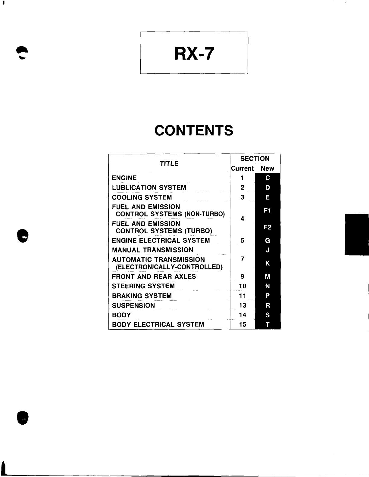
RX-7
CONTENTS
•
TITLE
ENGINE
LUBLICATION
COOLING SYSTEM
FUEL AND EMISSION
CONTROL
-----
---
FUEL AND EMISSION
CONTROL
ENGINE ELECTRICAL SYSTEM
MANUAL
AUTOMATIC TRANSMISSION
(ELECTRONICALLY -CONTROLLED)
FRONT AND REAR AXLES
STEERING SYSTEM
BRAKING SYSTEM
SUSPENSION
BODY 14
BODY ELECTRICAL SYSTEM 15
-
--
--
---
--
--
-
SYSTEM
-
SYSTEMS
--- ---
SYSTEMS (TURBO)
--
TRANSMISSION
--
----
(NON-
----
-
--
-
-----
TURBO)
---
--
SECTION
1
2
3
4
5
7
9
10
11
13
•
Page 3
-
c
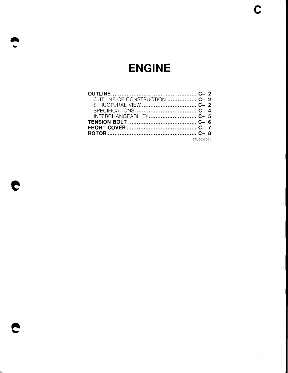
ENGINE
e
OUTLINE
OUTLINE OF CONSTRUCTION
STRUCTURAL VIEW
SPECIFICATIONS
INTERCHANGEABILITY
TENSION BOLT
FRONT COVER
ROTOR
..................................................
................................
....................................
............................
........................................
.........................................
....................................................
.................
C-
CC-
C-
C-
C-
CC-
97UOCX
2
2
2
4
5
6
7
8
501
e
Page 4
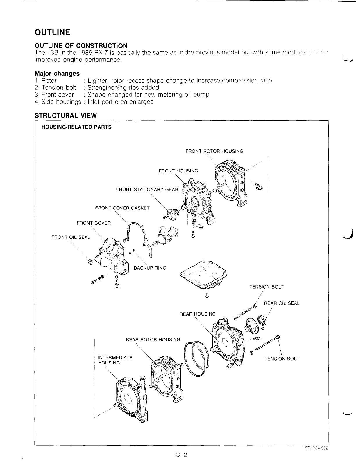
OUTLINE
OUTLINE OF CONSTRUCTION
The 13B
improved engine performance.
Major changes
1.
Rotor : Lighter, rotor recess shape change to increase compression ratio
2.
Tension bolt : Strengthening ribs added
3.
Front cover : Shape changed for new metering
4.
Side housings : Inlet port erea enlarged
STRUCTURAL VIEW
HOUSING-RELATED PARTS
in
the 1989
RX-7
is
basically the same as
FRONT HOUSING
in
the previous model but with some modli
oil
pump
FRONT ROTOR HOUSING
c:=:-
_
FRONT OIL SEAL
._)
REAR HOUSING
REAR ROTOR HOUSING
INTERMEDIATE
HOUSING
C-2
·-
97UOCX·502
Page 5
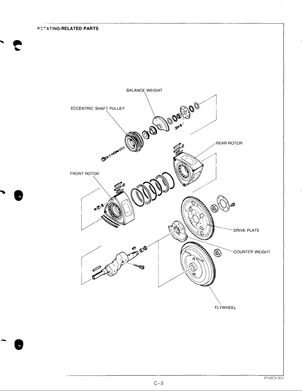
;:;'"'TA
~
TING-RELATED
PARTS
BALANCE WEIGHT
ECCENTRIC PULLEY
REAR ROTOR
' •
FRONT ROTOR
DRIVE PLATE
COUNTER WEIGHT
FLYWHEEL
-.
C-3
Page 6
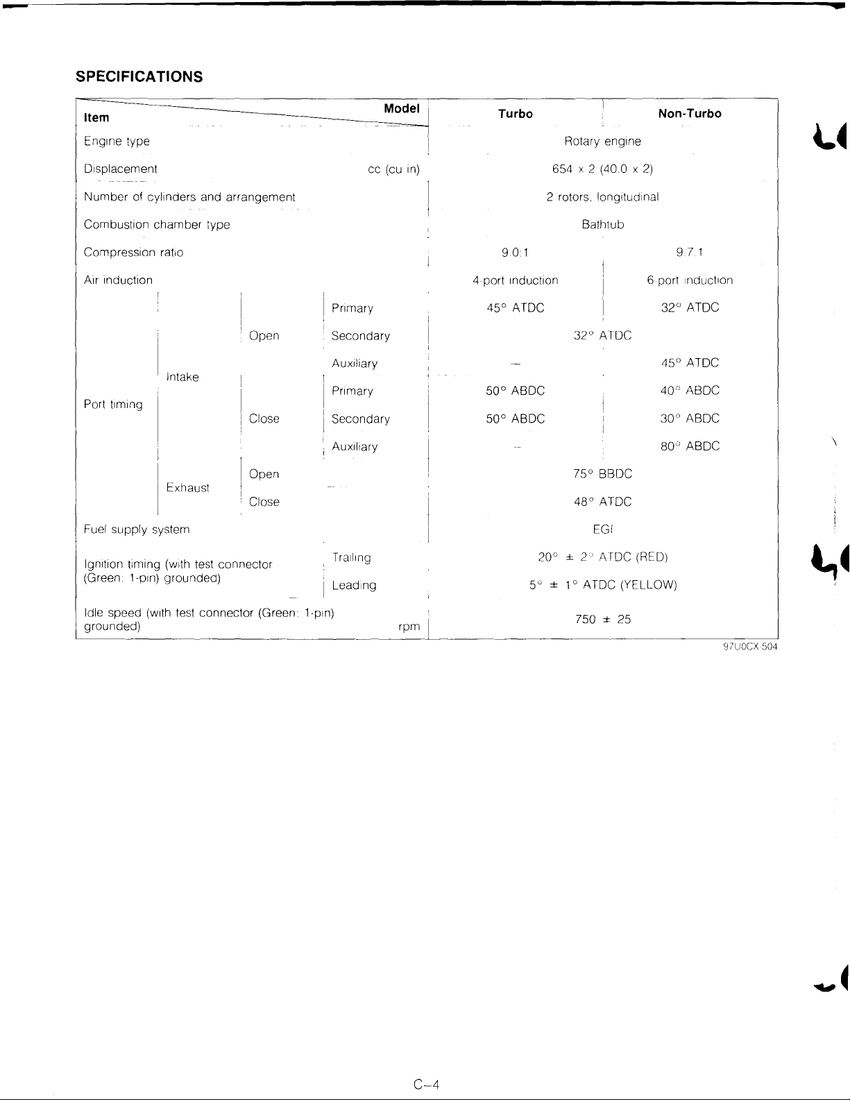
SPECIFICATIONS
cc
Model
(cu
1n)
Item
Eng1ne type Rotary eng1ne
Displacement
Number
Combustion
Compression
A1r
Port
of cyl1nders and
chamber
Induction
t1m1ng
rat10
Intake
Exhaust
arrangement
type
Open
Close
Open
Close
Pnmary 4S0 ATOC
Secondary
Auxiliary
Pnmary
Secondary
Auxil1ary
Turbo Non-Turbo
6S4 X 2 (40.0 X
2 rotors. longitudinal
Bathtub
9.0 1
4 port
1nduct1on
32°
ATOC
S0°
ABOC
soo
ABOC
0
7S
BBDC
48°
ATOC
2)
6 port
32°
4S
40°
30°
80"
9.7 1
1nduct1on
ATOC
0
ATOC
ABOC
ABOC
ABOC
~~
\
Fuel
supply
lgn1t1on
(Green
Idle
grounded)
t1ming
1-p1n)
speed
system EGI
(w1th
grounded)
(w1th
test
test
connector
connector
(Green
Tra1l1ng
Lead1ng
1-pln)
rpm
± 2 ' ATOC (REO)
20°
so
±
1 o ATOC (YELLOW)
750 ± 25
l,~
97UOCX 504
C-4
Page 7
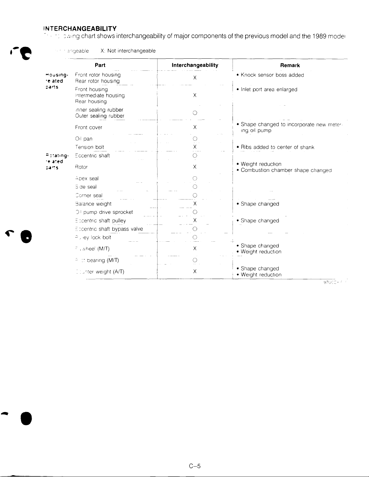
INTERCHANGEABILITY
:::
,.,,ng
chart shows interchangeability of major components of the previous model and the 1989 mode'
X Not interchangeable
...
ousmg-
·~
ated
;:.a
r1S
;;
:~at1ng-
-~
a~ed
=~~s
Part
Front rotor hous1ng
Rear rotor hous1ng
Front
hous1ng
i ntermed1ate housing
Rear housing
seal1ng
nner
Outer sealing rubber
Front cover
Orl
pan
Tens1on
::ccentnc shaft
Rotor
~~pex
S de
seal
:::orner
3a',ance weight I
J I pump dnve sprocket
: :centr1c
'C
=centnc shaft bypass valve - -
~
. ·ey lock bolt
~
.
:.
heel
• · beanng
.1ter
rubber
bolt
seal
seal
shaft pulley t
(MIT)
(MIT)
we1ght
(A/T)
-1
. -
i
---1
I
+
J
-~·
.
l
I,
Interchangeability
X
X
0
X
0
X
0
X
0
0
0
X
0
X
0
0
X
0
X
Remark
• Knock sensor boss added
• Inlet port area enlarged
• Shape changed to Incorporate new
tng
Oil
pump
• Ribs added
•
We1ght
•
Combustion chamber shape changed
• Shape changed
• Shape changed
• Shape changed
•
We1ght
•
Shape changed
•
We1ght
'
to
center of shank
reduct1on
reduct1on
reduct1on
metw
•
C-5
Page 8
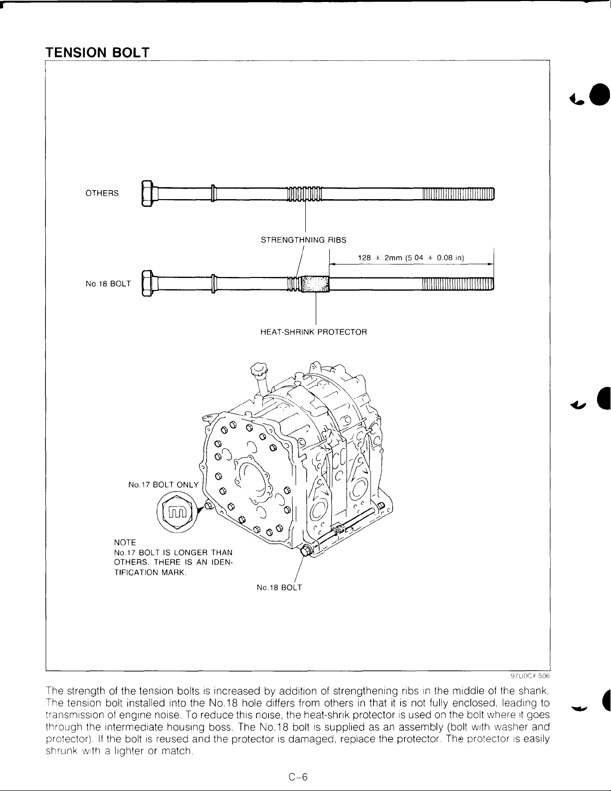
TENSION BOLT
...
OTHERS
No.18 BOLT
(}1
T
STRENGTHNING RIBS
128 ± 2mm
HEAT-SHRINK PROTECTOR
lllllllllllllllllllllllllllllll
(5.04 ± 0.08 in)
NOTE
No.1? SOL
OTHERS. THERE IS AN IDENTIFICATION
The strength of the tension bolts
The tension
transmiss1on of eng1ne noise. To reduce this noise. the heat-shrik protector
through the intermediate housing boss. The No. 18
protector).
shrunk
bolt installed into the No. 18 hole differs from others
If
the bolt
w1th
a l1ghter or match.
T IS LONGER THAN
MARK.
1s
increased by addit1on of strengthening ribs
is
reused and the protector
No.18 BOLT
bolt
is
damaged, replace the protector. The protector
C-6
in
that
is
supplied as an assembly (bolt
in
the middle of the shank.
it
is
not fully enclosed. lead1ng to
is
used on the bolt where
w1th
washer and
97UOCI 506
1t
goes
1s
easily
Page 9
,
.•
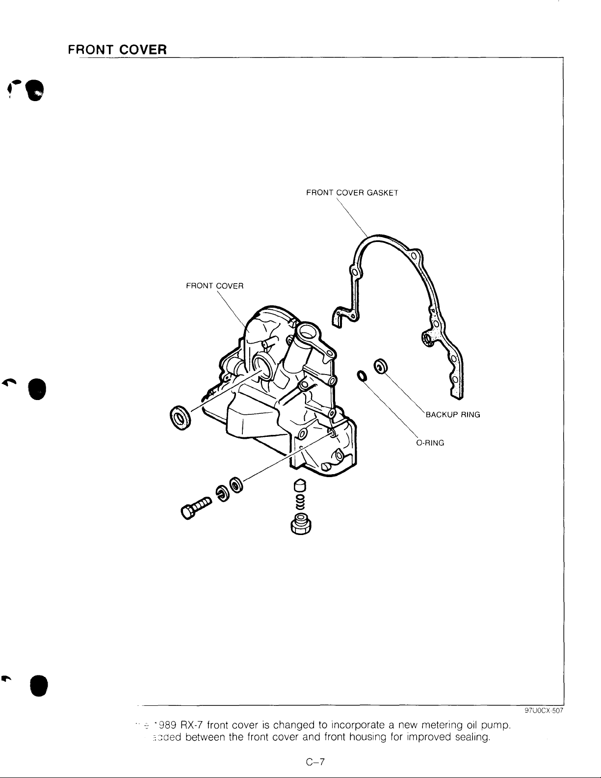
FRONT COVER
FRONT COVER GASKET
FRONT COVER
~.
~BACKUP
0-RING
RING
•
~
· 989
:::::ded
RX-7
front cover
between the front cover and front housing for improved sealing.
is
changed to incorporate a new metering
C-7
oil
97UOCX 507
pump.
Page 10
ROTOR
TURBO
RIBS
NON-TURBO
RIBS
~
~
\
A
/J
I
c--~~
v
A A
~
A~
1 0.9mm (0.43 in)
,_
4
8.8mm (0.35 in)
r---/1
~-
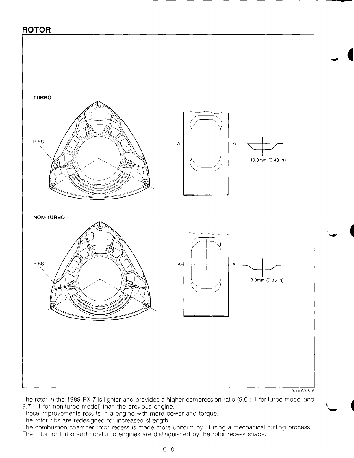
The rotor
9.7 :
These improvements
The rotor ribs are redesigned for increased strength.
The combustion chamber rotor recess
The rotor for turbo and non-turbo engines are distinguished by the rotor recess shape.
in
the 1989
1 for non-turbo model) than the previous engine.
RX-7
results
is
lighter and provides a higher compression ratio (9.0 : 1 for turbo model and
in
a engine with more power and torque.
1s
made more uniform by utilizing a mechanical cutting process.
97UOCX 508
C-8
Page 11
...
D
LUBRICATION SYSTEM
OUTLINE
OUTLINE OF CONSTRUCTION
STRUCTURAL VIEW
SPECIFICATIONS
INTERCHANGEABILITY
METERING OIL PUMP
OUTLINE
OPERATION
FAIL-SAFE FUNCTION
SERVICE POINT
OIL FILTER
..................................................
................................
....................................
............................
...............................
...............................................
...........................................
.............................
.......................................
............................................
.................
D-
D-
D-
D-
D-
D-
DDD-
D-
D-
97UODX 501
2
2
2
3
3
4
4
5
5
6
6
-
-
Page 12
OUTUNE
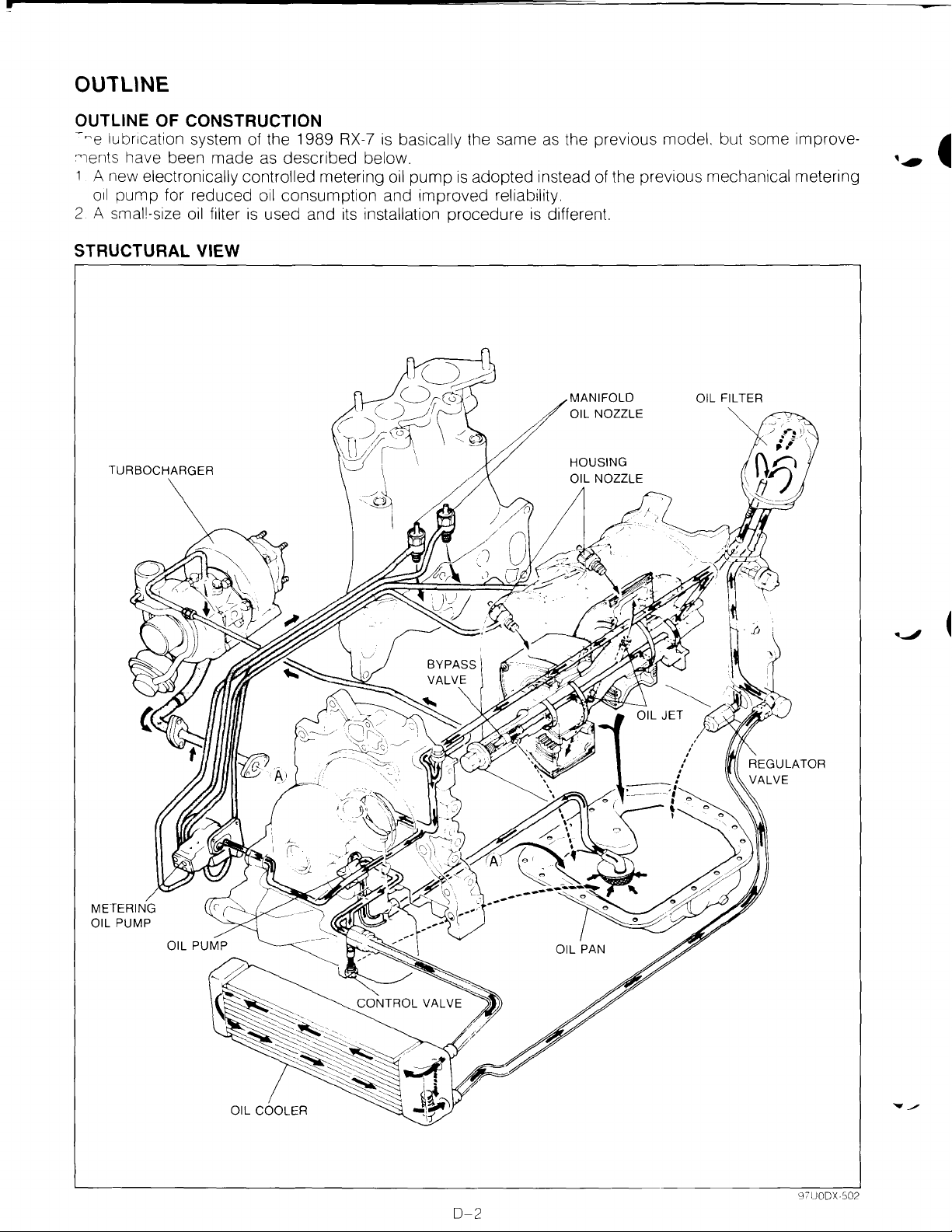
OUTLINE OF CONSTRUCTION
-~e
lubncation system of the 1989
"lents have been made
1 A new electronically controlled metering
oil
pump for reduced
2 A smal!-size
oil
filter
as
described below.
oil
consumption and improved reliability.
is
used and
STRUCTURAL VIEW
RX-7
its
installation procedure
is
basically the same
oil
pump
is
adopted instead
as
the previous model. but some improve-
of
the previous mechanical metering
is
different.
MANIFOLD
OIL NOZZLE
TURBOCHARGER
HOUSING
0-2
Page 13
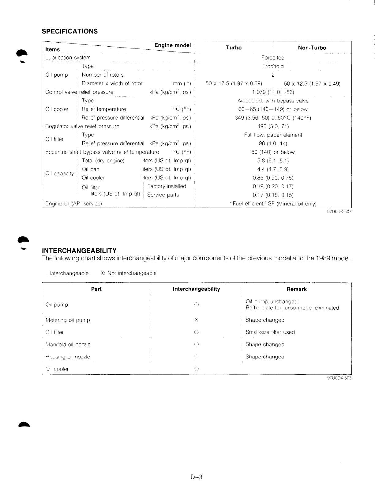
SPECIFICATIONS
Items
Lubncat1on system
Type
011
pump
Control valve relief pressure
Oil cooler
Regulator valve
Oil filter
Eccentnc shaft bypass valve
Oil
capaCity
Eng1ne
oil
(API
Number
1
1 D1ameter x
Type
Rel1ef
Rel1ef
Type
Rel1ef
Total (dry
011
Oil cooler
011
serv1ce)
of rotors
w1dth
temperature
pressure dlfferent1al kPa
rel1ef
pressure kPa
pressure
eng1ne)
pan
filter , actory-1nstalled
l1ters
(US qt Imp qt) i Serv1ce parts
of rotor
d1fferent1al
rel1ef
temperature
Engine model
kPa (kg/cm
(kg/em'.
(kg/em'.
kPa
(kg/em'.
l1ters
(US qt. Imp qt)
liters
(US qt. Imp qt)
l1ters
(US
\ F
I
qt
_____
mm
2
oc
oc
Imp
.
ps1)
(°F)
ps1)
(°F)
(1n)
ps1)
ps1)
qt)
_[_________
50 X 17.5
Turbo
(1
97 X
A1r
349
Fuel
Force-fed
Trocho1d
069)
1.079 (11.0.
cooled.
60-65
(140-149)
(3
56. 50)
490 (5.0. 71)
Full flow.
98
60 (140) or below
5.8 (6 1 5.1)
4.4 (4.7. 3
0.85 (0.90. 0
0.19 (0.20 0 17)
0.17 (0.18. 0 15)
eff1c1enr·
2
50 X 12.5 (1.97 X 0.49)
156)
w1th
bypass valve
or below
at
60°C
paper
element
(1.0. 14)
9)
75)
SF
(M1neral oil only)
Non-Turbo
(140"F)
----
___
97UODX
_j
507
INTERCHANGEABILITY
The following chart shows interchangeability of major components of the previous model and the 1989 model.
Interchangeable X Not Interchangeable
Interchangeability
X
______________________________
Remark
Oil
pump
unchanged
Baffle plate for turbo model
Shape
changed
Small-s1ze filter used
Shape
changed
el1m1nated
97UODX
j
503
011
pump
rl1eterlllg
0 I
f1lter
--1ous1ng
J
_c_o_o_le_r
Part
oil
pump
oil
nozzle Shape cr1anged
______________
~
0-3
Page 14
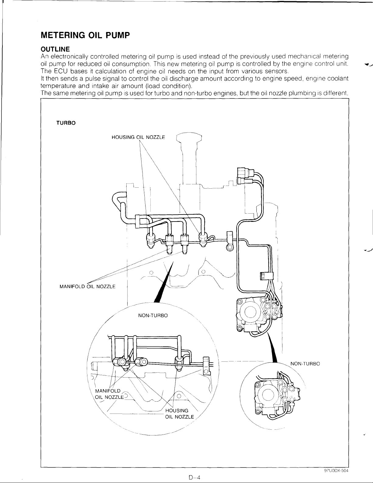
METERING OIL PUMP
OUTLINE
An electronically controlled metering
oil
pump
The ECU bases
It
then sends a pulse signal to control the
for reduced
it
calculation of engine
oil
consumption. This new metering
temperature and intake air amount (load condition).
The same metering
TURBO
oil
pump
is
used for turbo and non-turbo engines, but the
HOUSING OIL NOZZLE
oil
pump
is
used instead of the previously used mechan1cal metering
oil
needs on the input from various sensors.
oil
discharge amount according to engine speed,
oil
pump
is
controlled by the
oil
nozzle plumbing
eng1ne
eng1ne
control unit.
coolant
1s
different
...
~
MANIFOLD OIL NOZZLE
NON-TURBO
~
I
NON-TURBO
0-4
97UODX·504
Page 15
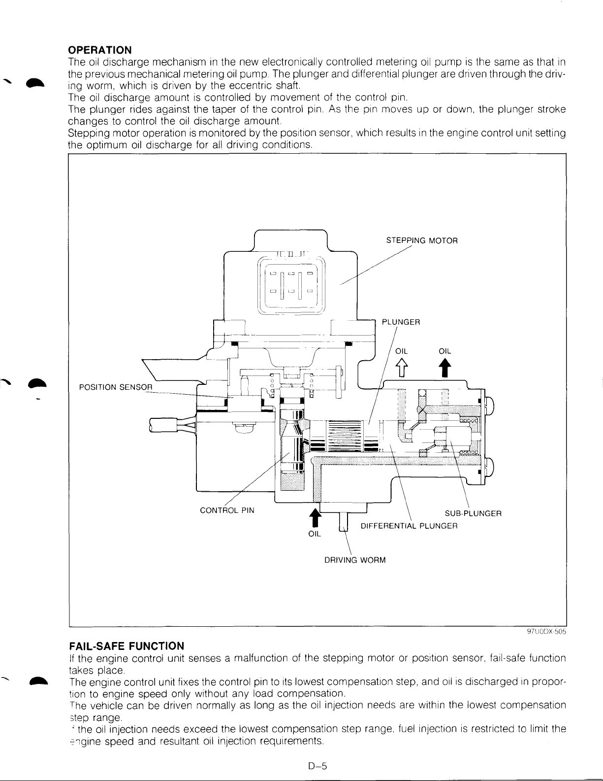
OPERATION
The
oil
discharge mechanism
the previous mechanical metering
is
ing worm, which
The
oil
discharge amount
The plunger rides against the taper
changes to
Stepping motor operation
the optimum
control the
oil
driven by the eccentric shaft.
oil
discharge for
in
the new electronically controlled metering oil pump
oil
is
controlled by movement
discharge amount.
is
monitored by the
all
driving conditions.
is
the same
pump. The plunger and differential plunger are driven through the driv-
of
of
the control pin.
pos1t1on
the control
As
the
sensor, which results
p1n.
p1n
moves up or down, the plunger stroke
in
the engine control unit setting
STEPPING MOTOR
as
that
/
in
CONTROL PIN
f
OIL
DRIVING WORM
DIFFERENTIAL PLUNGER
FAIL-SAFE FUNCTION
If
the engine control unit senses a malfunction of the stepping motor or
place.
takes
The engine control unit fixes the control pin to
tion to engine speed
The
vehicle can be driven normally
step range.
' the
oil
injection needs exceed the lowest compensation step range. fuel injection
~1gine
speed and resultant oil injection requirements.
only without any load compensation.
as
long
its
lowest compensation step, and
as
the
oil
injection needs are within the lowest compensation
D-5
posit1on
SUB-PLUNGER
97UODX 505
sensor. fail-safe function
oil
is
discharged
is
restricted to limit the
in
propor-
Page 16
SERVICE POINT
OIL FILTER
The 1989
The service oil filter
RX-7
has a small-size
is
oil
filter. The factory-installed oil filter differs from the service parts oil filter.
the same as that used for the Mazda 323 B-series engine. '
.....
Oil filter capacity
ctory 1nstalled
rvice part
-
--·-----·-----
019
0.17
(0.20, 0.17)
(0
18.
0.15)
liters (US qt,
_,]
Imp
qt)
97UODX 508
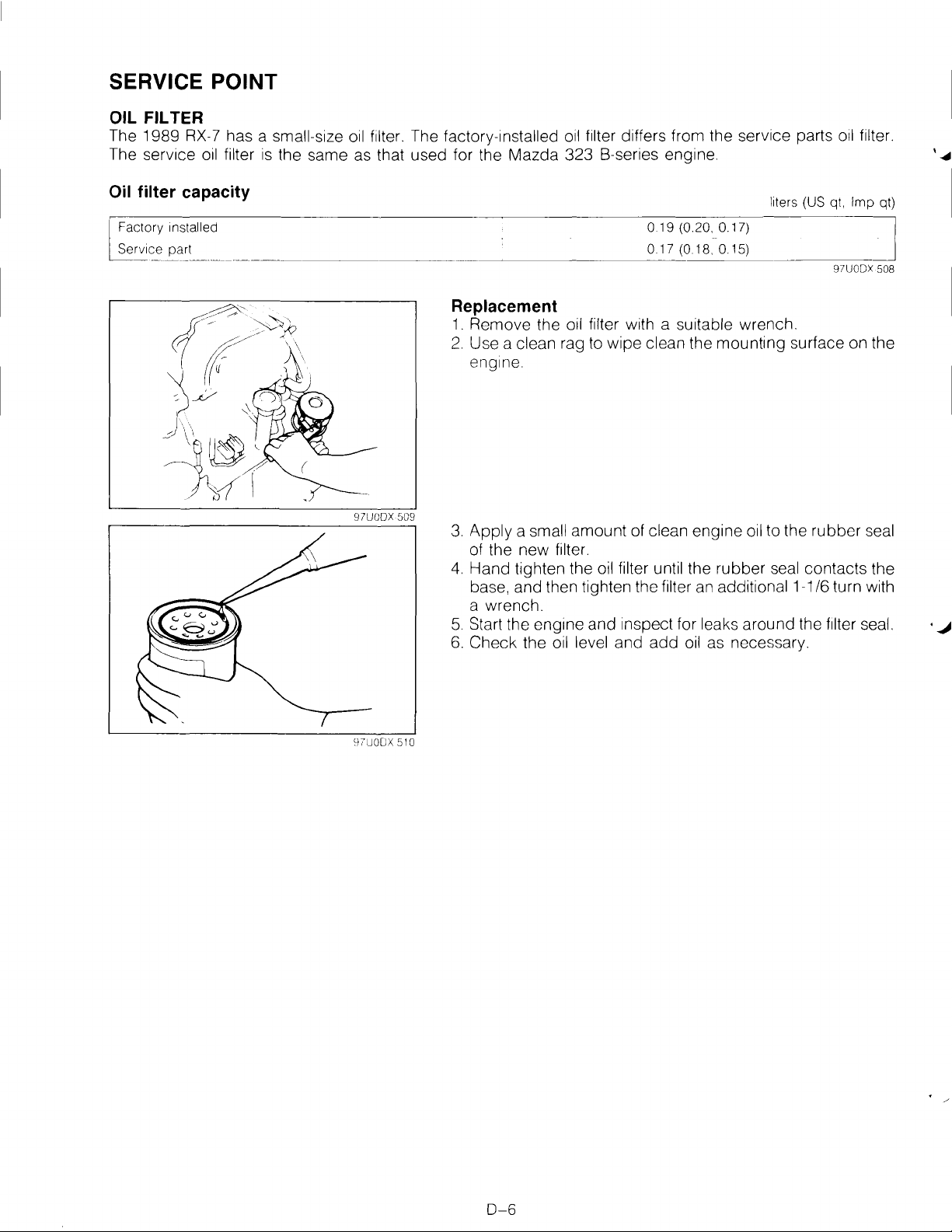
Replacement
1.
Remove the oil filter with a suitable wrench.
2.
Use a clean rag to wipe clean the mounting surface on the
engine.
3.
Apply a small amount of clean engine oil to the rubber seal
of the new filter.
4.
Hand tighten the oil filter until the rubber seal contacts the
base, and then tighten the filter an additional 1-1/6 turn with
a wrench.
5.
Start the engtne and inspect for leaks around the filter seal. ·
6.
Check the oil level and
add
oil as necessary.
.J
0-6
Page 17
COOLING SYSTEM
E
OUTLINE
OUTLINE OF CONSTRUCTION
STRUCTURAL VIEW
SPECIFICATIONS
INTERCHANGEABILITY
COOLING FAN
WATER PUMP
THERMOSTAT
RADIATOR
..................................................
................................
....................................
............................
..........................................
..........................................
..........................................
...............................................
..................
E-
EEE-
E-
EEEE-
97UOEX 501
2
2
2
3
3
4
5
6
7
-
Page 18
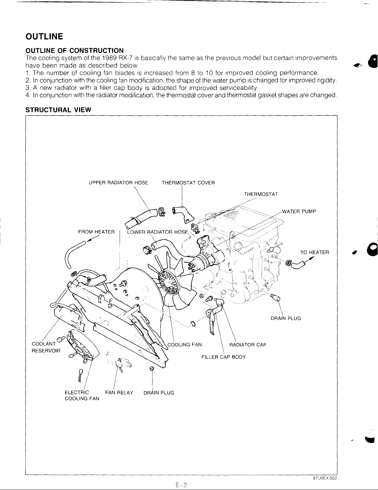
OUTLINE
OUTLINE
The cooling system of the 1989
have been
1.
The number of cooling fan blades
2.
In
3.
A new radiator with a filler
4.
In
STRUCTURAL VIEW
OF
CONSTRUCTION
RX-7
is
basically the same as the previous model but certain improvements
made
conJunction with the cooling
conjunction with the radiator modification, the thermostat cover and thermostat gasket shapes are changed.
as described below.
fan
modification, the shape of the water pump
cap
body
is
increased from 8 to 1 0 for improved cooling performance.
is
changed for improved rigidity.
is adopted for improved serviceability.
THERMOSTAT
~
WATER PUMP
RESERVOIR
FROM HEATER
(/
fj
ELECTRIC
COOLING
FAN
FAN RELAY
RADIATOR CAP
FILLER CAP BODY
DRAIN PLUG
E-2
97UOEX-502
Page 19
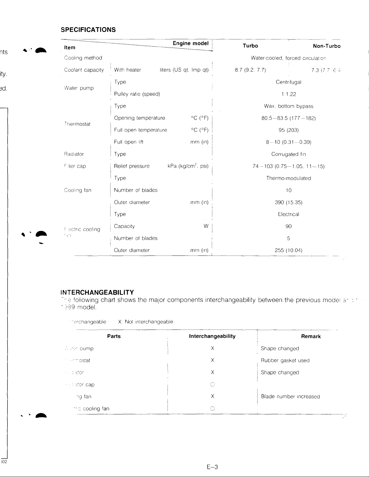
SPECIFICATIONS
nts
Item
Cool1ng
Coolant capac1ty
/Vater
Tl1ermostat
Rad1ator
'ller
Cool1ng fan
method
pump
cap
W1th
heater
Type
Pulley
rat1o
Type
Open1ng
Full
Full
[
Type
Relief pressure
Type
Number
Outer
Type
temperature
ope'l
open
of blades
d1ameter
liters (US qt.
(speed)
temperature
l1ft
Engine
kPa
mode~
Imp
°C
oc
mm
2
(kg/cm
•
mm
qt)
(°F) i
(oF) i
(1n)
ps1)
(1n)
Turbo
Water-cooled,
8.7 (9.2 7.7)
forced
Ce'ltnfugal
Non-Turbo
c1rculat:o'l
7.3
(7
7 c
~
1 1.22
Wax. bottom
I
80.5-83.5
95
I
8-10
Corrugated
74-103
(0.75-1.05.
Thermo-modulated
bypass
(177
-182)
(203)
(0.31-0.39)
f1n
11-15)
10
390
(15 35)
Electncal
-
mm
w
(1n)
255
90
5
(10.04)
:
(;CtriC
COOling
i Capac1ty
Number
Outer d1ameter
of blades
INTERCHANGEABILITY
~.
;co
following chart shows the major components interchangeability between the previous model
· ?39 model.
· ·_?•changeable
· ":Jstat
:
c::or
:
:::Jr
cap
'lQ fan
Parts
X
Not
Interchangeable
Interchangeability
X
X
X
c
X
Shape
Rubber
Shape
Blade
changed
gasket used
changed
number
Increased
Remark
c:·
)02
··::
::ooling fan
0
E-3
Page 20
COOLING FAN
FAN DRIVE
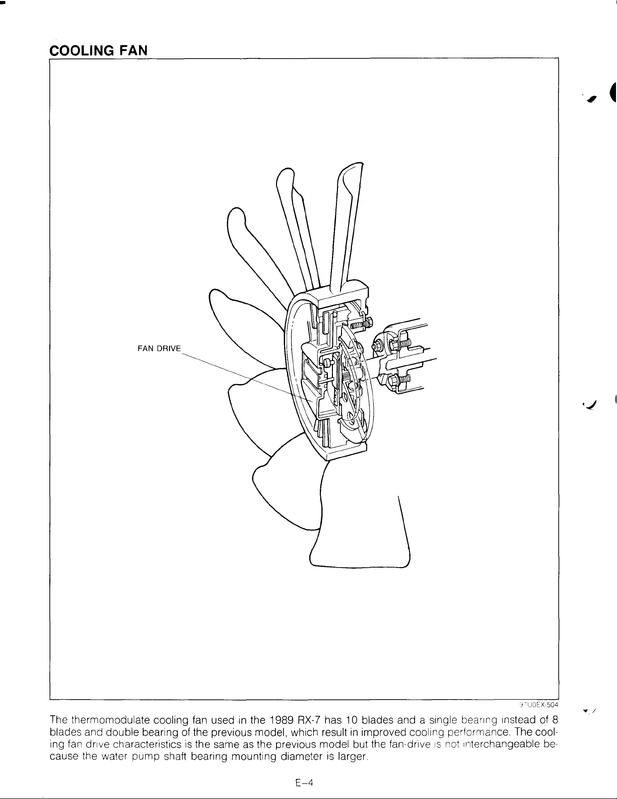
The thermomodulate cooling fan used
in
the 1989 RX-7 has 10 blades and a
blades and double bearing of the previous model, which result
ing fan drive characteristics
cause the water
pump
is
the same as the previous model but the fan-dr1ve
shaft bearing mounting diameter
is
larger.
E-4
s1ngle
in
improved cooling performance. The cool-
bear1ng 1nstead of 8
1s
not Interchangeable be-
•_/
Page 21
WATER PUMP
SHAFT BEARING
PULLEY BOSS
\
BEARING HOUSING
@~
EXTRA RIBS
I
I
WATER
WATER PUMP BODY
PUMP GASKET
"'
\ -
-
97UOEX
:.
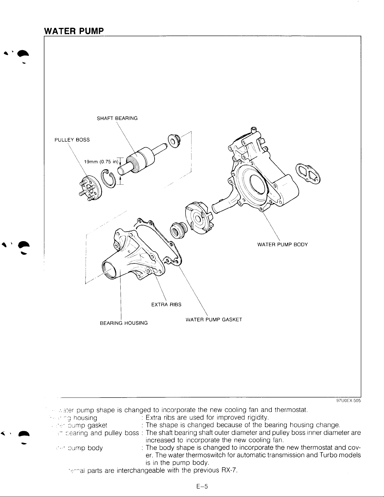
:=::er
pump shape
•.
·-g
housing : Extra ribs are used for improved rigidity.
·-.·
:Jump gasket : The shape
...
:::earing and pulley boss : The shaft bearing shaft outer diameter and pulley boss inner diameter are
·.
· :Jump body : The body shape
·-=-·~al
parts are interchangeable with the previous
is
changed to incorporate the new cooling fan and thermostat.
is
changed because of the bearing housing change .
increased to incorporate the new
is
changed to incorporate the new thermostat and cover. The water thermoswitch for automatic transmission and Turbo
is
in
the
pump
body.
RX-7.
cooling fan.
models
E-5
505
Page 22
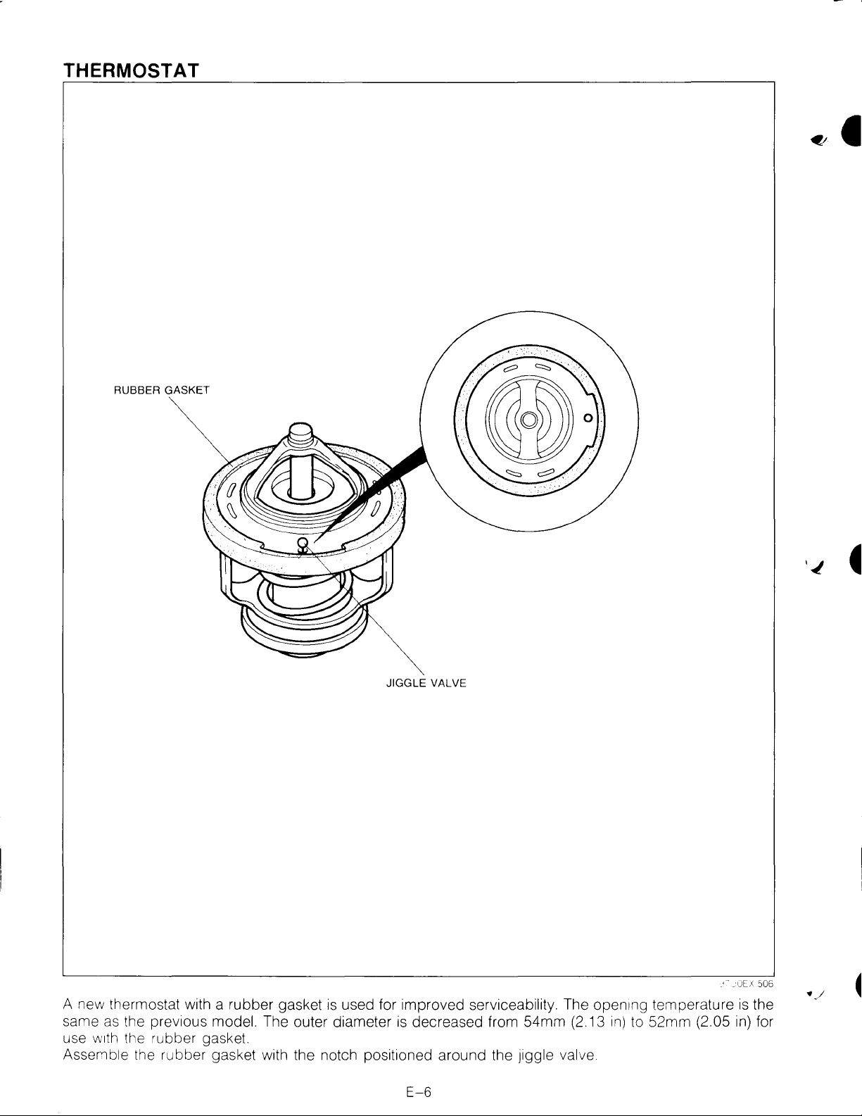
THERMOSTAT
RUBBER GASKET
JIGGLE
A new thermostat with a rubber gasket
same
as
the prev1ous model. The outer diameter
use
w1th
the rubber gasket.
Assemble the rubber gasket with the notch positioned around the Jiggle valve
is
used for improved serviceability. The open1ng temperature
VALVE
is
decreased from 54mm (2.13
1n)
to 52mm (2.05
is
in)
the
for
E-6
Page 23
'
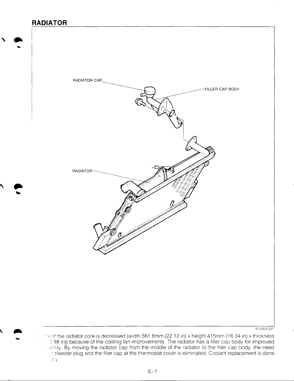
RADIATOR
..
RADIATOR CAP
FILLER CAP BODY
RADIATOR
-
.:::::of
the radiator core
J 98
in))
because of the cooling fan improvements. The radiator has a filler cap body for improved
· :::J
l1ty.
By moving the radiator cap from the middle of the radiator to the filler
, - bleeder plug and the filler cap at the thermostat cover
':'j
is
decreased (width
561
.Smm (22.12
E-7
in)
x height 415mm (16.34
is
eliminated. Coolant replacement
in)
cap
body, the need
97UOEX-507
x thickness
is
done
Page 24
F1
•
FUEL
AND
EMISSION
CONTROL SYSTEMS
{NON-
OUTLINE
OUTLINE OF CONSTRUCTION
EMISSION CONTROL SCHEMATIC
DIAGRAM
SYSTEM DIAGRAM
VACUUM
WIRING DIAGRAM
SPECIFICATIONS
VARIABLE DYNAMIC EFFECT INTAKE
(VDI) SYSTEM
FUEL SYSTEM
MIXING PLATE
SERVICE POINT
CONTROL SYSTEM
AIRFLOW METER
THROTTLE-IDLE-POSITION AUTO-
ADJUSTING SYSTEM
LEAN BEST-IDLE CONTROL SYSTEM
SPARK ADVANCE FEEDBACK SYSTEM
SERVICE POINT
SELF-DIAGNOSIS FUNCTION
DESCRIPTION
MALFUNCTION
SWITCH MONITOR FUNCTION
................................................
...........................................
HOSE ROUTING DIAGRAM
.......................................
........................................
......................................
.......................................
TURBO)
................
................................
.......
.................................
...................................
....................................
.................................
..................................
...........................
.......
....................................
...................
CODE
NUMBER
................
.............
....
'J7UOII
F1F1-
F1F1F1F1-10
F1-11
F1-12
F1-13
F1-13
F1-14
F1-15
F1-15
F1-16
F1-17
F1-18
F1-19
F1-20
F1-20
F1-21
F1-25
c,[11
2
2
4
8
9
•
Page 25
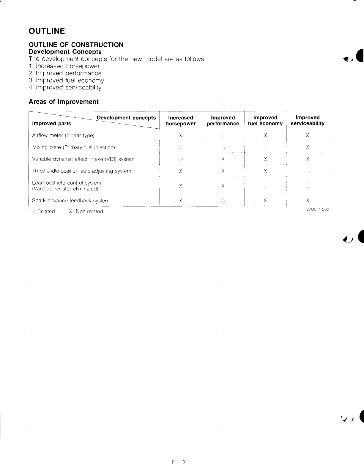
OUTLINE
OUTLINE OF CONSTRUCTION
Development
The
development concepts for the new model are
1.
Increased horsepower
2.
Improved performance
3.
Improved fuel economy
4.
Improved serviceability
Concepts
as
follows
Areas of
Improved parts
Airflow
M1x1ng
Vanable
Throttle-1dle-pos1t1on auto-adJUSting system
Lean best
(Vanable res1stor el1m1nated)
Spark
'.
Related X
Improvement
Development concepts
meter
(L1near type)
plate
(Pnmary
dynam1c effect 1ntake (VOl) system
1dle
advance
fuel
1nJ8ct1on)
control system
feedback
Non
system
related
Increased
horsepower
X
X
X
X
Improved
performance
X
X
X
Improved
fuel
I
I
economy
X
X
X
X
Improved
serviceability
X
X
X
X
97UOF1 502
Page 26

System Construction
ENGINE
CONTROL
UNIT
I
THROTTLE-IDLE-POSITION
AUTO-ADJUSTING SYSTEM
IMPROVED SERVICEABILITY
[AIRFLOW
IMPROVED
PERFORMANCE
METER]
SPARK ADVANCE
FEEDBACK SYSTEM
IMPROVED PERFORMANCE
LEAN BEST-IDLE CONTROL SYSTEM
MPROVED
MPROVED SERVICEABILITY
FUEL ECONOMY
--MIXING
'.CREASED HORSEPOWER
'.'PROVED PERFORMANCE
'.'PROVED
PLATE~~--,
FUEL ECONOMY
'
L____
97UOF1 503
F1-3
Page 27

EMISSION CONTROL SCHEMA TIC DIAGRAM
Input
Devices
OXYGEN SENSOR
ENGINE
CONTROL UNIT
(INCLUDES
ATMOSPHERIC
PRESSURE
SENSOR) i '
WATER
THERMOSENSOR /
PRESSURE
SENSOR
/'J
,../'
/
r,/'•'
THROTTLE SENSOR
(FULL RANGE)
THROTTLE SENSOR
(NARROW
~'
l·
.•
··y"'l
,
(o
;:((/
1
J
..
t',l
-\~v
'\\,
<~))
~
,-,
/'
).\
.-
/,
;J
. I
I
<""'
.,)
RANGE)
HEAT HAZARD
SENSOR
INHIBITOR SWITCH
(A/T)
IGNITION SWITCH
NEUTRAL SWITCH (M/T)
,,~L--,--------BACK-U
LIGHT
(MIT)
5TH
P
AND
SWITCH
AIRFLOW METER
(INCLUDES INTAKE
AIR
THERMOSENSOR) /
CRANK ANGLE SENSOR
F1-4
MILEAGE SENSOR
CIRCUIT OPENING
OIL PRESSURE
SWITCH
MAIN RELAY
RELAY
(A/T)
97UOF1-504
Page 28

Output Devices
SOLENOID VALVE
(BYPASS AIR CONTROL)
FUEL PUMP
RESISTOR
RELAY
INJECTOR
(SECONDARY)
/
DOUBLE
THROTTLE
DIAPHRAGM
DASH POT
.
~~
CHECK CONNECTOR
(GREEN: 3-PIN)
'.
I-::
VALVE
VALVE
AIR CONTROL
INJECTOR (PRIMARY)
SOLENOID
(ACCELERATED
WARM-UP SYSTEM)
PURGE CONTROL
VALVE
··~
/?
(\.
::;c-lEF
c _ENCER
::::
· =
:::n
AIR
CHAMBER
A/C
:..BLE
DYNAMIC EFFECT INTAKE
INDUCTION
RELAY
AIR PUMP
(PRESSURE REGULATOR
SOLENOID
CONTROL)
'A
VALVE
IGNITION COIL WITH IGNITER
(LEADING)
TEST CONNECTOR
(GREEN 1-PIN)
'~~~IGNITION
COIL
L I WITH IGNITER
SOLENOID
(RELIEF)
SOLENOID
(SWITCH)
CHECK CONNECTOR
(SELF-DIAGNOSIS
CHECKER, GREEN: 6-PIN)
VALVE
VALVE
(TRAILING)
F1-5
Page 29

Fuel Devices
TO FUEL FIL TEA
FROM PRESSURE REGULATOR
TO CHARCOAL CANISTER
-
------
FUEL TANK
CHARCOAL----I-CANISTER
CHECK CONNECTOR
(FUEL PUMP,
YELLOW: 2-PIN) ',...
PULSATION DAMPER
(WITH DELIVERY PIPE)
FUEL
PUMP~
RESISTOR
RELAY .
~
~
...
~-
nc-n
•
:-------'-·
-
Q(_
PRESSURE
(WITH DELIVERY PIPE)
"---
REGULATOR
INJECTORS
~
~~F-f-1'"-------1
G
F1-6
'.I
97UOF' 506
Page 30

Exhaust Devices
SPLIT
AIR
MAIN CONVERTER
FRONT CONVERTER
PIPE
INSULATOR COVERS
97UOF1 507
F1-7
Page 31

CJ)
-<
CJ)
-i
m
3:
c
)>
G)
::D
I
II
)>
3:
CJ)
T1
II
I
I
AIRFLOW METER
(INCLUDE INTAKE
THERMOSENSORI
AIR
.
i
if
~==~
~¢-'--~>..I/
PURGE CONTROL
VALVE
INTAKE AIR
THERMOSENSOR
I I
I~
I
!
SOLENiiD
(PRESSURE REGULATOR
I
~C~ON~T~R~O~L~)
VALVE 1
~~~~~---_j
1
FUEL PUMP
RESISTOR RELAY
EC AT CONTROL p
UNIT
<D
---J
Ell
§ REAR DEFROSTER SWITCH
01
SWITCHES HEADLIGHT SWITCH SWITCH IAiTI
FOG LIGHT SWITCH '¥""
~~-------------B-L_o_w_E_R--SW--IT_c_H
l
_____________________
INHIBITOR •
Q}(
'V I IV
,(\
M_A_,I_N~~C-~0_-N~V-~E--R~T-E-R-----------------------------------------------------------------F~U~E~l~~F~IL~T~E~R----------------------------__j
FRONT CONVERTER .
I CHECK VALVE TANK
I(\
- - -l==r-FUEL PUMP
OXYGEN
SENSOR
-~~~--.
'\I
¥-'
FUEL
l
;-=fT!-;?
r =
CHECK-AND-CUT VALVE
,...
Page 32

VACUUM HOSE ROUTING DIAGRAM
PRESSURE
REGULATOR
---------,
ACTUATOR
(VOl)
(
INTAKE
---"'RESSURE REGULATOR CONTROL
MAN IF OLD--tt--11--+--4+--+-
• ARIABLE
JYNAMIC
;:>QAT
"
EFFECT INTAKE
INDUCTION
\
\
~
SOLENOID VALVE
(VDI: WHITE)
SOLENOID VALVE
ORANGE)
(PAC:
SOLENOID
I (RELIEF BLUE)
SOLENOID VALVE
(SWITCH GRAY)
VALVE
FUEL FILTER
-
--;:
BODY (A/T)
F1-9
97UOF 1
007
Page 33

1N
PST
1(]
Q_T
VALV[
INJECTOR
(FRONT
PRII•t4.RYl
~
INJECTOR
(FRONT
SECONOAIIYl
0
!Gl
-El
INJECT()!;>
II?EAII
Pllltr.IAIIYJ
I
E
A 6
IYI
Q£0<:
(YELLOW:
iNJECTOR
I
REAR
SECONOMlYJ
CCHECT~
2--PINl
.
~
AIR
TI-EFMJ-
SENSrn
Lfi
~
Tf£Ml-
SENSOO
J]
POSITION
""'
SENS<f>
E}J
SENSOR
AIRFLOW
I£TER
c=-
~t---{a]~
~(GY)
SD....e«liD "'ALliE
(SWITOil
~-Ill
SCLENOIO
VALVE
fF£LIEF)
H(G)
~"'
CCHECTOO
GHEEN J P1N1
'-----f-++~---1SQEjjjl_NOIO
'-----+++~-liiil
~(0)
18YPA.SS AIH
POflT
AIR
SCLENOIO
16-PORT
SOlEI'<liO
•PRESSURE
VALVE
CON'HOL
'"'
SOLENOID
68
VALVE
INDUCTION
VALVE
REGULATOH
I
CONTROL!
sa...EN'liO
VALVE
I
>-I-
I
FUEL
PL'o!P
liES I STOll
RELAY
161
jh~
FAN
SWITO+
0
0
:~~:
:~~
:§§:
,,_,_,
•...:...:,
~
~-~
~
(R'
EC-A.T
TH~BmE
SENSOR
1NARROW
1-1ANGE•
~~J
TI-A:ITill
~~ANGE
~------+-~ra~~~
'------------jc---4JE
(ACCELERATED
~~w
SOLENJID
(VAAIABL.E
f--CF=
f--Dn
B
STEP
1MfTEHtNG
EFFECT
;--\
MOTORS
VALVE
DYNAMIC
INTAKE)
OIL
WARM-UP
PUMP
1MOP
SYSlEMt
1
m~--------------------------------------------------------------------------------------------------------------------------------------------------------------~
~
(J
•
Page 34

SPECIFICATIONS
Item
Idle speed (Test connector (green
A1r
cleaner Element type
Type
Throttle body
Dash pot
Fuel
tank
Fuel
f1lter
Pressure regulator
Fuel
pump
11ector
Secondary)
"leal
\,ja1n
(Pnmary and
hazard sensor
silencer
;;n1t1on
t1m1ng
(Test connector (green 1-pln) grounded)
J stnbut1on
advance
Spark
: e up system
= . :lass
a1r
control system
· afterburn valve Operat1on
Throat d1ameter i Pnmary mm
Water
thermovalve
Adjustment speed rpm
Capacity
Low pressure
High pressure _
Type
Regulated pressure
Type
Outlet pressure kPa (kg/cm
Dr1ve
InJeCtion
Operation temperature
Capac1ty cc (cu
Type
Type
A/C
"D"
range
Model
1-p1n)
grounded) rpm
Secondary
Operat1on temp.
l1ters
(US gal. Imp gal)
kPa (kg/cm
volume cc (cu ln)/15 sec. i
t1me
mm
oc
2
2
oc
(In)
(1n)
(oF)
,
ps1)
,
ps1)
(°F) i
in)
rpm
rpm
sec.
138
EGI
750 ± 25 (for AlT
Long
Honzontal - draft
45 (1.772)
(1
45
M/T.
67-77
A/T
60-70
Nylon
235-275
441-588
MIT 10.300 (628.3) x
Lead1ng
Tra1l1ng
(153-171)
(140-158)
2,700-3.100
70 (18.5, 15.4)
6 (164 and 45 mesh)
F1lter
D1aphragm
(2.4-2.8,
Impeller
(4.5-6
Voltage dnve
111-118
105-115
20° ± 2°
Eng1ne
Eng1ne
MIT. 875 A/T 800
750
(at warm
L1near
MIT
AlT. 0
engine
..
N Range)
l1fe
wet
(2
slaj:l~---
772) X 2
paper
34.1-39
(1ntank)
0,
64.0-85
(6.8-7.2)
(221-239)
2,
A/T
5°
± 1 o ATDC
control
control
1.60-2.20
un1t
un1t
eng1ne)
soleno1d
52-0.92
3 barrel)
or more
or more
8)
3)
12.000 (732) x 2
ATDC
97UOF1 511
F1-11
Page 35

VARIABLE DYNAMIC EFFECT INTAKE (VOl) SYSTEM
~.-
s systern cors.sts of the VOl valve, solenoid valve, and actuator. The
.
~
::::
Ooerat
-OeENGINE
~=EED
on
of
th1s
system
OPEN V %
~
,
·.
is
as shown below.
~
0
HIGH ENGINE SPEED J
(VDI VALVE: OPEN CONDITION)
VOl
valve
is
built into the exten mani-
VDI VALVE
= INTAKE AIR
·~
PRESSURE WAVE
•
co...,
I
..
.....
• • • PRESSURE WAVE
ABOVE
5,200
::
:.·,.;
ANGLE SENSOR
:
-::~;Jine
:
·-::::s~re
~~-::speed,
.
::: . ::
·· . ::
:·-::
,·
;:::s
operation, when intake air flows to a port closed by the rotor a pressure wave
wave then goes toward the open intake port, compressing the intake air along the way.
the VOl valve
. e opens and the pressure wave quickly pressurizes the intake air through the shortened path.
'::xced
c-essunzation
1nto
remaining
VDI VALVE
OPENING
AREA
LARGE
rpm
_______
INTAKE AIR
AMOUNT
is
closed, causing the pressure wave path to be long. At high engine speed,
the combustion chamber
is
induced at the time of the opening of the intake port, when the high-pressure
in
the working chamber generates strong pressure waves that rush into the intake
at
all
engine speeds.
(m1/h)
SMALL~--------~------~
0
ENGINE SPEED
JI
5,200 8,000
(rpm)
97UOF1
is
created.
509
At
F1-12
Page 36

FUEL SYSTEM
MIXING PLATE
INJECTOR
SECONDARY
INJECTOR
AIR
SOCKET
BLEED
AIR
BLEED
SOCKET
· 19 plate
·
:J.ke
air port.
97UOF2-508
is
installed at the tip of primary Injector to direct the primary fuel inJection fuel directly into
F1-13
Page 37

SERVICE POINT
PULSATION
®----INSULATOR
NEW 0-RING
~======s~~----AIR
INTERMEDIATE
HOUSING
'---"
~MIXING
BLEED SOCKET
PLATE
~·
MIXING PLATE
The pr1mary inJector
1 Install the parts
2 Use a new
3
A1
gn 1re 1abs
in
Insulator and 0-rings.
of
NOTCH
is
installed noting the following:
the order shown
the mixing plate with the notches
in
the figure.
F1-14
TAB
in
the intermediate housing.
'UDF2 509
~··
Page 38

CONTROL SYSTEM
AIRFLOW METER
SLIDING CORE
INTAKE
THERMOSENSOR
AIR
~
CONNECTOR
I
AIR BYPASS
PASSAGE
INTAKE AIR
THERMOSENSOR
t
AIRFLOW METER
t
~-.
-~
eter
-
:
Jn.
97UOF2-513
is
changed from a vane type to a linear type. The sliding core moves parallel to the airflow
there
is
little air damping and low air resistance
as
a result of the streamlined shape.
F1-15
Page 39

THROTTLE-IDLE-POSITION AUTO-ADJUSTING SYSTEM
· · · SENSOR OPEN
~·
NARROW
FULL
RANGE
NARROW
FULL RANGE
RANGE
RANGE
SENSOR
CLOSED
(0%)
150/o
SENSOR
OPEN (100%)
I
: APPROX.
I
SENSOR CLOSED
AUTO-ADJUSTING
___..~
300/o
SENSOR CLOSED
SENSOR OPEN
AREA
SENSOR
OPEN (100%)
50/o
.:.
··e:.ly
developed
-· ~ system automatically
.:. · =:
e
tre
narrow range throttle sensor
:
=:::on
·
.:: S-::
~:::erat1on
c.·
,
auto-adJUSting system, the eng1ne control unit will compensate for actual output values of
···
e output
respectively for fail-safe operation
:;;
~e
:::
25° o respect1vely for fall-safe operation.
is
for the full range sensor
control
throttle-idle-position auto-adjusting system
less than
un1t
15%
compensates
I~
I~
:
THROTTLE AUTO-ADJUSTING AREA
IDLE
POSITION
compensates
or
more
within the range from
250/o
~'
for certain variations
is
set to
output
than
25%
at idle, the engine control
is
the same. The sensor
is
in
a signal of
is
set to reg1ster a
5%-25%.
850/o
I
FULL
THROTTLE
97UOF2 514
incorporated
the output signal of the throttle sensors .
20%
w1thin
of full-open. With the throttle idle-
the engine control unit.
15%-25%.
un1t
If
over or
fixes the value
15°/o
s1gnal
under
the s1gnal1s fixed at
at
at
1dle,
15%
and the
and
5%
\.!.
F1-16
Page 40

LEAN BEST-IDLE CONTROL SYSTEM
WATER THERMO
INHIBITOR
SWITCH
(A/T )
SENSOR
EC-AT
CONTROL
UNIT
~
rL
NEUTRAL SWITCH (M/T
CLUTCH
PiS PRESSURE SWITC
:::EAR DEFROSTER SWITCH
SWITCH (M/T
A/C SWITCH
BLOWER SWITCH
HEADLIGHT SWITCH
FOG LIGHT SWITCH
(ONLY
CANADA
)
)
H
)
I
~
---c:
=
~~LE
SENSOR (NARROW
RANGE)
ENGINE CONTROL UNIT
DETECTION OF ENGINE
WARM CONDITION
DETECTION OF ENGINE
NO-LOAD CONDITION
(ONLY FOG LIGHT SWITCH:
DETECTION OF
ENGINE LOAD CONDITION)
--
DETECTION OF ENGINE
IDLE CONDITION
t
~
DETERMINA-
TION
LEAN BEST-
~
f-
IDLE
CONDITION
OF
I
FUEL
INJEC-
TOR
BATTER
y
re
--o ••
• ANGLE SENSOR (NE
. _
-::j
fuel consumption and reduced exhaust emissions
·.V1th
this system, the engine control unit sets fuel injection
- .
:;1ng
lean misfire and rough idle.
SIGNAL)
DETERMINATION OF LEAN
BEST-IDLE AMOUNT
at
idle, the lean best-idle control system
F1-17
K
97UOF2-515
at
idle to the leanest amount possible
is
Page 41

SPARK ADVANCE FEEDBACK SYSTEM (ENGINE AT IDLE)
SPARK
ADVANCE
FEEDBACK
AMOUNT
DETECTION OF
ENGINE IDLE
THROTTLE SENSOR
(NARROW RANGE)
CONDITION
1
I
-50-------------~------~----
oo
- - - - - - - - -,..---'--'
I
1
I
CRANK
SENSOR (NE SIGNAL)
ANGLE
DETERMINATION
OF
ADVANCE
SPARK
FEEDBACK
AMOUNT
I
IGNITION COIL
'
RS
rpm
DECREASED
TS:
RS:
TS
TARGET ENGINE SPEED
REAL ENGINE SPEED
RS
INCREASED
rpm
To
prevent rough idle caused by incorrect idle speeds, the spark advance feedback system controls the
spark advance. The engine
tion
timmg to
obta1n
the preprogrammed target speed
control unit judges the engine speed (real speed:
(TS).
RS)
and then adjusts the igni-
F1-18
LJ7UOF2
516
Page 42

SERVICE POINT
THROTTLE SENSOR ADJUSTMENT
IDLE MIXTURE ADJUSTMENT
/
.....
__________________________
::::' adJUStment: Not usually necessary unless throttle sensor unit
auto-adjusting system automatically compensates.
~
JJustment
Not
necessary because of lean best-idle control system. (Varrable
eliminated.)
F1-19
is
replaced.
_
Th
rottle-rdle-pos ~ :::
res
~-
~
=-
Page 43

SELF-DIAGNOSIS FUNCTION
DESCRIPTION
When troubles are suspected
Failures of individual input and output devices are indicated and retrieved from the control unit as malfunc-
tion
code
numbers.
Note
The control unit constantly checks for malfunction of the input devices.
tion of output devices only during a 3-second period after the ignition switch has been turned
ON
while the test connector
in
the
ma1n
is
1nput
devices or output devices, check for the cause with the SST.
grounded.
It checks for malfunc-
IGNITION COIL
WITH
IGNITER---
(TRAILING SIDE)
~JE~~~~::LEJ~~-~
CRANK ANGLE '
SENSOR (G-SIGNAL)
~
_
---.
---,
FAIL-SAFE
FUNCTION
_L
WATER
THERMOSENSOR
AIRFLOW~
METER
INTAKEAIR
THERMOSENSOR
(AFM)
INTAKE AIR
THERMOSENSOR /
(ENGINE)
~~
~
\)
~
~
--
/
DETECTION
OF
MALFUNCTION
WARNING
FUNCTION
&
MALFUNCTION
CODE
FUNCTION
-
-
-=-
~
~
Wu~~~~:GE;-1
~
THROTTLE~
SENSOR Q
(NARROW-RANGE) .
PRESSURE--SENSOR
OXYGEN
METERING
PUMP POSITION c o
SENSOR o
SENSOR-\
OIL--~~1._
-~---·-
-
·-
1
- o
.__/
-~
-----'
ATMOSPHERIC
PRESSURE
SENSOR
TEST CONNECTOR
(GREEN: 1-PIN)
F1-20
97UOF2-024
Page 44

MALFUNCTION CODE NUMBER
SST
Jg H018
3elf-Dragnosis
Checker
9A1
SHF
UIAGIIlSrS
97UOF1-512
CHfClER
Inspection Procedure
1.
Warm
stop
2.
Connect the SST to the check connector (Green: 6-pin) and
the negative battery
Set the select switch to position
3.
Connect a jumper
1-pin)
up
the
engine
it.
and a body
to normal
operating
terminal.
A.
wire between the test
ground.
temperature
connector
(Green:
and
,..
• • I
I~
:: :
J.AGNOSIS
~-,
11\T/"
• G
·1cr1:o:
G/
1_1.11_1!
0
~-,'-[-\-'---\-'-
SElF
--~
DIAGNOSIS
~
CHECKER
MALFUNCTION
V CODE NUMBER
::111-:1/
--
--
CHECKER
97UOF1
97UOF1
514
510
4.
Turn the ignition switch ON.
5.
Check
sounds
6.
If
7.
If
than 20 sec.,
control unit
And
voltage. Replace
88
88
that
88
flashes on the digital display
and
the buzzer
for 3 sec. after turning the ignition switch ON.
does
flashes
check
not flash,
and
check
(1
F)
the
check
the buzzer
the
check
sounds
continuously for
for a short circuit between the
terminal and
engine
the
check
control unit
engine
control unit
connector (Green: 6-pin).
(3X)
connector
and (3Z) terminal
if
necessary
perform Step 4 again.
8.
Check
9.
Start the
for any malfunction
engine
and
check
code
numbers.
for further malfunction
numbers.
10.
If
a malfunction
cause of the
code
problem.
number
is
indicated,
check
Note
Cancel the malfunction code numbers by performing
the after-repair procedure
following repairs.
F1-21
wiring.
more
engine
and
code
for the
Page 45

Principle of code cycle
Malfunction codes are determined
1.
Malfunction code cycle break
The time between malfunction
as
below by use of the MIL and Self-Diagnosis Checker
code
cycles
is
4.0 sec. (the time the MIL and checker buzzer are off).
97UOF1-515
1 CYCLE
ON
OFF
MALFUNCTION CODE
CYCLE
4.0 SEC.
2. Second digit of malfunction code (ones position)
The digit
are on
in
the ones position of the malfunction code represents the number of times the MIL and buzzer
0.4 sec. during one cycle.
4
0.4
~---~
MALFUNCTION
CYCLE BREAK
4.0 SEC.
1 CYCLE CODE
ON
JU\fl"
OFF
-1--!-
0.4
SEC. SEC.
BREAK
ffilll
-----
9MUOF 1
543
CODE No.: 03
89lll!4X
565
3. First digit of malfunction code (tens position)
The digit
are on 1
The MIL and buzzer are off for 1.6 sec. between the long and short pulses.
in
the tens position of the malfunction code represents the number of times the MIL and buzzer
.2
sec. during one cycle.
1 CYCLE
;-----~----.,
FIRST DIGIT SECOND
1.6 4.0 SEC.
SEC.
MALFUNCTION
CODE
CYCLE
BREAK
DIGIT
F1--22
CODE
No.
89U04X
22
566
Page 46

Code number
Caution
a)
If there
is
more than one failure present, the lowest number malfunction code
first, the subsequent malfunction codes appear
b)
After repairing
ble,
at least 5 seconds to erase the malfunction code memory.
In
put devices
all
failures, turn the ignition switch OFF, disconnect the negative battery ca-
in
order.
is
displayed
Code
No.
l'
:2
devices
Input
lgn1110n
with
(Trail1ng
Crank angle sensor Broken
(Ne
coil
1gn1ter
s1de)
s1gnal)
Malfunction
plug. broken
ClfCUit
c1rcuit
Malfunction
of spark
w1re.
w1re.
short
short
Fail-safe function
T
rail1ng-s1de
pulse cut
Fuel
InJeCtion
1 lion cut
1gn1t1on
and
1gn1-
Output signal pattern
(Self-Diagnosis Checker or MIL)
Jl
I
angle sensor Broken
Crank
(G
s1gnal)
ClfCUit
short Fuel InJection and
w1re.
t1on
cut
1gn1
I
Bas1c
A1rflow
meter (AFM) Broken
Water thermosensor
a1r
Intake
'll
t
thermosensor (AFM)
;ntake
a1r
sensor
Throttle
1Full
Pressure sensor Broken
:
·1take
:Yessure)
-'ltmosphenc pres-
~u
Built
J x ygen sensor
:-
eedback system
-
· •ottle sensor
.arrow range)
'.'eter1ng
· -s,t,on sensor
·
.'
.c:enng
'.'8P)
·.·-:c-:er
'.':JP)
thermo- Broken
(Eng1ne)
sensor
range)
man1fold
re
sensor
(A
ECU)
oil
oil
oil
TP)
pump
pump
pump
1n
:1g
ClfCUII
Broken
ClfCUI!
Broken
ClfCUit
ClfCUit
Broken
ClfCUit
ClfCUII
Malfunct1on1ng ECU
Oxygen
below 0 55V
system
operat1on
Oxygen
ma1ns 0 SSV
system
operat1on
Broken
circuit
Broken
CirCUit
Malfunct1onmg
tors.
broken
or
malfunct10n1ng
Malfunct
on1ng
broken
111re.
1
t:on.ng
ECU.
short
w1re.
w1re.
short
short
w1re.
w1re.
short
short
w1re.
short
w1re.
sensor
output
rema1ns
80
sec
aher
beg1n1ng
sensor
output
· 0
sec
after
begm1ng
short Throttle valve open1ng
w1re.
short
w1re.
MOP.
steo
w1re.
short
ECU
MOP.
step
srort c rcu
t.
rralfunc-
alter1ator
or
'
1
FiB
re
FIB
mo
c1rcu1t
,"lotors
battery
fuel InJection
amount and
t1m1ng
Coolant temp. input
f1xed
Intake
f1xed
Intake
f1xed
Throttle valve open1ng
angle input signal
at
20%
Intake
1nput
mmHg (29.9 inHg)
Atmospheric pressure
1nput
760
mmHg
Feedback system canceled (For EGI)
Feedback system canceled (For EGI)
angle
at
full open
MOP
f1xed
Bas1c
and
1Qn1t1on
MOP
Bas1c
and
1Qn1t1on
Basic fuel
amount and ignit1on
t1m1ng
F1-23
f1xed
at
80°C
a1r
temp.
at
20°C
a1r
temp.
at
20°C
open
man1fold
s1gnal
s1gnal
1nput
smallest
fuel
1nJect1on
f1xed
smallest
fuel
1nj8ct1on
InJeCtion
fixed
1gn1!10n
(176°F)
(68°F)
(68°F)
pressure
f1xed
f1xed
(29.9
s1gnal
t1m1ng
tmng
1nput
1nput
at
amount
f1xed
amoun:
f1xed
f1xed
760
at
1nHg)
f1xed
open
open
..
llll
n
fU
Jll
J1l
run
JUI
rull
JUII[
i
m
Jrull
ImJII
97UOFI-516
Page 47

Output devices
Code
No.
25
! Soleno1d valve (Pressure regulator control (PRC))
I
26
Step motor (Metenng oil pump)
1
I
I
I
f Split air solenoid valve
30
I
I
31
Soleno1d valve
j Soleno1d valve
32
Output devices
(Rel1et)
(Sw1tch)
I
Port
a1r
33
34
Soleno1d valve
soleno1d valve
(Bypass
a1r
control)
I
-
~---
1
Soleno1d valve
38
40
Soleno1d valve (6-port
41
Soleno1d valve (Vanable dynam1c ettect 1ntake (VOl))
51
I Fuel
pump
71
Injector
73
InJector (Rear secondary)
(Accelerated warm-up system (AWS))
1nduct1on)
res1stor
(Front secondary)
relay
97UOF1
'-I
517
F1-24
Page 48

SWITCH MONITOR FUNCTION
Preparation
SST
i 49 H018
•
Self-D1agnos1s
· Checker
Individual switches can be monitored by the SST.
19.
9A1
Note
The test connector must
NEUTRAL SWITCH
CLUTCH SWITCH
BACK-UP LIGHT
5TH SWITCH (M/T)
HEADLIGHT
BLOWER
REAR DEFROSTER
SWITCH
FOG LIGHT
INHIBITOR SWITCH
SWITCH---------+---------'
(IF EQUIPPED)
r-.
~
,-,~~-:J
I I I I
1
S!
t:
~IAGJlO~IS
~~~E~K!R
97UOF2 064
BATTERY
(M/T)-------1------------,
(M/T)--------+--------,
AND--------~------~~~~
SWITCH-----------11----------'
________
SWITCH--------:::::;~~=====~----t--.....,.
(A/T)'----------1
be
grounded and the ignition switch
ENGINE CONTROL UNIT
-+------~
ON
(engine stopped).
~~CTOR
IQIIUII:ftll
:1
517
97UOF2066
,..
Inspection Procedure
1.
Warm up the engine to normal operating temperature:::·
stop
it.
2.
Connect the SST
the negative battery terminal.
3.
Connect a jumper wire between the test connector (G';:c-
1-pin) and a ground.
4.
Turn the 1gnition switch ON, then check that the me·
lamp illuminates
cording to the function table.
Caution
a)
When any one of the switches are activated, the
monitor
b)
Do
lamp will be on.
not start the engine.
(GREEN: 1-PIN)
to
the check connector (Green:
when each switch
is
made to funct,c·-
6-pir'
::·
97UOF1 519
F1-25
Page 49

Function Table
Switch
Neutral sw1tch (MIT)
Back-up light
5th
SWitch
Clutch
lnh1b1tor
Headl1ght
Blower sw1tch
and
(MIT)
switch (MIT)
sw1tch (A/T)
sw1tch
Self-Diagnosis Checker (Monitor lamp)
Lamp-ON Lamp-OFF
Sh1ft
1.2.3or4
Sh1ft
5th
1
Pedal
Except
range
Sw1tch
Sw1tch
(At
OK)
gear
any
transmiSSIOn to
transmiSSIOn
depressed
N and P
ON
ON
fan
speed
Neutral
Neutral
Pedal released
N
Sw1tch
Sw1tch
and
pos1t1on
pos1t1on
P range
OFF
OFF
Possible cause
(When incorrect)
• Neutral sw1tch malfunction
•
Open
wcu1t
between neutral
ECU
1R
term1nal. neutral
ground
•
Back-up
Open
•
5th sw1tch
and
• Clutch sw1tch malfunction
•
Open
ECU
ground.
1 •
lnh1b1tor
! • EC-AT control
Open
•
and
Headlight
•
Open
•
ECU
tery
•
Blower
Heater relay malfunction
•
Heater control
•
Open
•
and
l1ght
and
5th sw1tch malfunction
circuit between
and
ECU 1 T term1nal.
ground
c1rcu1t
between clutch sw1tch
10
term1nal. clutch sw1tch
clutch switch
switch malfunct1on
ur11t
malfunct1on
C1rcu1t
between EC-A T control
ECU.
sw1tch malfunction
c1rcu1t
betweer1 headl1ght
3L
terminal, headl1ght sw1tch
l1ne
sw1tch malfunct1on
un1t
malfunction
c1rcu1t
ECU
between heater control
30
term1nal
sw1tch
Back-up
and
ACC
sw1tch
and
l1ght
overdnve
and
circuit
sw1tch
and
and
and
un1t
and
un1t
and
bat
Rear defroster sw1tch
Fog
l1ght
sw1tch
(If equ1pped)
Sw1tch
1
Sw1tch
(Only
light)
ON
ON
equip
fog
i Sw1tch OFF
Sw1tch
OFF
• Rear
i •
1
1
• Fog
•
defroster
Open
c1rcu1t
and
ECU 3P term1nal. rear defroster sw1tch
and
ground
l1ght
sw1tch malfunction
Open
c1rcuit between fog
ECU 1 S term1nal. fog
battery
sw1tch
malfunction
between rear defroster sw1tch
l1ght
switch
and
l1ght
switch
and
97U0r
I 5?0
F1-26
Page 50

FUEL AND EMISSION
CONTROL SYSTEMS
(TURBO)
F2
20
OUTLINE
OUTLINE OF CONSTRUCTION
EMISSION
DIAGRAM
SYSTEM DIAGRAM
VACUUM
WIRING DIAGRAM
SPECIFICATIONS
FUEL SYSTEM
MIXING PLATE
SERVICE POINT
TURBOCHARGER CONTROL SYSTEM
SYSTEM CONSTRUCTION
COMPLETELY-IN
TWIN SCROLL TURBO
TURBO
SYSTEM
CONTROL SYSTEM
AIRFLOW METER
THROTTLE-IDLE-POSITION AUTO-
ADJUSTING SYSTEM
LEAN BEST-IDLE
SPARK
SERVICE POINT
SELF-DIAGNOSIS FUNCTION
DESCRIPTION
MALFUNCTION
SWITCH MONITOR FUNCTION
................................................
................
CONTROL
...........................................
HOSE ROUTING DIAGRAM
........................................
......................................
BOOST PRESSURE
.............................................
ADVANCE
.......................................
SCHEMATIC
................................
.................................
...................................
....................................
......................
DEPENDENT
.........................
CONTROL
.................................
..................................
...........................
CONTROL
FEEDBACK
....................................
CODE
SYSTEM
SYSTEM
...................
NUMBER
................
.............
.......
.......
.......
....
F2F2-
F2F2F2F2-10
F2-11
F2-12
F2-12
F2-13
F2-14
F2-14
F2-15
F2-16
F2-17
F2-17
F2-18
F2-19
F2-20
F2-21
F2-22
F2-22
F2-23
F2-27
97UOF 2 501
2
2
4
8
9
,.
Page 51

OUTLINE
OUTLINE
Development
OF
CONSTRUCTION
Concepts
The development concepts for the new model are
1.
Increased horsepower
2.
Improved performance
3.
Improved fuel economy
4.
Improved serviceability
Areas of Improvement
Improved parts
Airflow meter (L1near type)
M1x1ng
plate (Pnmary fuel InjeCtion)
Completely-independent
Duty solenoid valve
(Turbo boost pressure control system)
Throttle-idle-position auto-adjuSting system
Lean best-Idle control system
(Vanable resistor elim1nated)
Development concepts
twin scroll turbo
Increased
horsepower
as
X
0
()
C)
X
X
follows:
Improved
.
performance
I
'-
0
X
X
X
X
Improved
fuel
economy serviceability
X
('
J X
X X
X
X
.~\
,j
Improved
X
X
C)
0
Spark
U•
advance
Related
feedback
X Non-related
system
X
0
X X
97UOF2 502
~·
F2-2
Page 52

System construction
LEAN BEST-IDLE CONTROL SYSTEM
IMPROVED
IMPROVED SERVICEABILITY
FUEL ECONOMY
THROTTLE-IDLE-POSITIO;J
AUTO-ADJUSTING SYSTEM
IMPROVED SERVICEABILITY
--SPARK
FEEDBACK
IMPROVED PERFORMANCE
ADVANCE
SYSTEM
DUTY SOLENOID VALVE
.-----MIXING
INCREASED HORSEPOWER
IMPROVED PERFORMANCE
IMPROVED
PLATE---
FUEL ECONOMY
~.
F2-3
[COMPLETELY-INDEPENDENT TWIN SCROLL TURBO
INCREASED HORSEPOWER
97UOF2 503
J
Page 53

EMISSION CONTROL SCHEMATIC DIAGRAM
Input
Devices
INTAKE AIR
THERMOSENSOR
(ENGINE)
NEUTRAL SWITCH
IGNITION SWITCH
ENGINE CONTROL UNIT
(INCLUDES
ATMOSPHERIC
PRESSURE
SENSOR) •
~
~-
PRESSURE /
SENSOR
AIRFLOW METER
(INCLUDES INTAKE
AIR THERMOSENSOR)
~\")
"··!
,VATER
THERMOSENSOR
~
·5-Jt.
'
. " ·
..
:~
··-~c-~.
•
' '
:1•
\ ..
1
CRANK
ANGLE
·'
~·
·'(<)
KNOCK
~
SENSOR
CLUTCH
SWITCH
11.!
''
• P/S PRESSURE SWITCH
/
II''/
iff,~~
i'l/~
I,
-J
:I
BATTERY
SENSOR
TEST CONNECTOR (GREEN
MILEAGE SENSOR
(No.1 AND No.2)
1-PIN)
F2-4
97UOF2 504
Page 54

Output Devices
INTERCOOLER
,.
- = CONTROL VALVE
INJECTOR
SOLENOID
(AIR SUPPLY VALVE
DASH
DOUBLE
DIAPHRAGM
PURGE CONTROL
~CHECK
(GREEN: 3-PIN)
~~
VALVE
POT
THROr
~
CONNECTC=
VAL.
_o:
0:
'504
~.
':"SILENCER
AIR CHAMBER
AIR PUMP
/
IGNITION COIL WITH IGNITER (LEADING)
F2-5
DUTY SOLENOID VALVE
(TURBO BOOST
CONTROL)
"'SOLENOID
REGULATOR CONTROL)
SOLENOID
CHECK CONNECTOR
(SELF-DIAGNOSIS CHECKER,
VALVE
VALVE (SWITCH)
PRESS~=::
(PRESSU~O:
GREEN ~ -
Page 55

Fuel Devices
•
PRESSURE REGULATOR
(WITH DELIVERY PIPE)
CHARCOAL CANISTER
F2-6
/
/
Page 56

•
Exhaust Devices
MAIN SILENCER
:R
=>E)
1
(
SPLIT AIR PIPE
-~"BOCHARGER
MAIN CONVERTER
FRONT CONVERTER
INSULATOR COVERS
J6
l
F2
7
Page 57

MILEAGE SENSOR (No 1
BACK-UP LIGHT
INTAKE AIR
-n
f'\)
I
(X)
PIS
HEAT
MOP
POSITION SENSOR
WATER
THROTTLE
PRESSURE
CRANK
CIRCUIT
REAR DEFROSTER SW
AND
PRESSUA~C
HAZARD
SENSOR
CLUTCH
NEUTRAL
FOG LIGHT SW
AND
5TH SWITCH
AIRFLOW
OXYGEN
SENSSR
THERMOSENS
SENS8R
SENS
THERMOSENS8R
KNOCK
SENS
ANGLE SENSOR
OPENING
HEADLIGHT SW.
BLOWER
CANADA
STAR~TER
D
No
~~
SW
METER
RELAY
SW
SW.
SiGNAL
0
~
2)
SW
R
R
R
~
RELIEF SILENCER
ECU
SELF-DIAGNOSIS
CHECKER
TEST
CONNECTOR
!GREEN
1-PIN)
~
(J)
-<
(J)
-i
m
s::
c
)>
C)
::::0
)>
s::
I
[I
(
FUEL
PUMP
Page 58

-n
1'\.)
I
c.o
'
-
SULlNUID
(ACCELELA TED WARM-UP SYSTEM)
VALVE:
L VALVE
FUEL TANK
<
)>
0
c
c
s::
:I:
0
CJ)
m
JJ
0
c
-i
z
G')
c
)>
G')
:0
)>
s::
CHECK VALVE
(ONE-WAY)
L
FIL TEA (HIGH PRESSURE)
Q) SOLENOID VALVE
CD
§
@SOLENOID
-n
rv
@
:::;
3 SOLENOID VALVE
WAS
ACTUATOR
(SWITCH)-GRAY
VALVE (PRESSURE REGULATOR
(RELIEF)-BLUE
TE
VALVE
CONTROL)-ORANGE
DUTY ENOID VALVE
(TURBO BOOST PRESSURE CONTROL)
'~~--------------------------------------------------------------------~
Page 59

P/5
P~ESSUAE
~
ONLY
CANADA
NEUTRAL
SACK
UP
SWITCH
LIGHT
5TH
TEST CONNECTOR A ( HEUTIIAL ON)
(GREEN:
1-PIN)
SWITCH
AND
SW I TOt
PST
(l_T
~
~
1;3
~~
~ ~
~2
~
~
3
~
~a~~~~~
l*l*l:.l~li!il
u
8
[i]
~~u
3~33
~~~
~
~ ~
~~
1~1~1~1:;:1
~
0~~
·"·
~~~~~
~
~i~~
~l:;:lii!l\il«i
:E
:a
z
G)
c
)>
G)
:a
)>
s::
~
~
~~~~~~
H~H~~~~~~
j;:;j.iil:;;l~~~i!i~lii!~liiil;ll
~
>
.,
~
\
"Tl
N
~
0
II
~
(N_y
CANADA
I
IGl
STARTER A 8 (Y)
AI...
TEJ=HAT(J:l
MALFUNCTION
INDICATOR
LANP
G3
~l
21
... , ·-
u
~
:t
~
~~
~ffi ~ ~
~~ ~~
~U)
::!'
[/)
·~
~
INJECTOR
(FRONT
SECONDARY)
Q£0<
(YELLOW;
I
NJECTOII
<REAR
SECONDARY)
CCN£CTOO
2-piNJ
i~
~h~
g~
~~
-:'
~
........
,...,..,
"""'
''I
!II
!I
~
FUEL
PLNP
RESISTOR
RELAY
(B)
h
FAN
SWITCH
~
~
c
0
~
N
6
0
~
INTAKE
AIR
T>£FM>-
SENSrn
WATER
~(L
II~-
c
"b:
A
...,
POSITION
flJ
AIRFLOW
I£TER
TI-AJTTLE
5ENSCf1
(N.lR"OW
RAta
I
~
THROTTLE
'3ENSOR
1F'JLL
RANGEl
(GY)
SOLENJIO
VALVE
(SWITCH)
SOLENJIO
VALVE
(FB.IEF)
'"'
PORT
AIR
SOLENOID
VALVE
t=u
DUTY
SOLEI'fJIO
VAL
BOOST
181
ID
PFESSIJE
VALVE
RfGULAT()f'l
VALVE
,AL\/f,
liE
I'Tl.RKl
i=::LJ(OI
SOLENOID
,PRESSURE
SOLENJ
,Aifl
')LIPPL•
~
:•H
"Fd-
--
STEP
MOTORS
!METERING
OIL
PU'v1P
r'IAOP))
CCNTROLJ
C()NTHCll
s•s
TE~1
OOL---------------------------------------------------------------------------------------------------------------------------------------------------------------~
(
~o..
~
Page 60

SPECIFICATIONS
Item
Idle
speed
(Test connector (green
A1r
cleaner r Element
Throttle
Dash pot
Turbocharger
Waste gate
Fuel tank
Fuel filter
Pressure regulator
f'uel
irld
--1eat
\1a1n
'J
S:Jark
-~
body
[ Lubncation
valve
f Capactty
pump
''Jector (Pnmary
Secondary)
hazard sensor
silencer
Jn1t1on
t1m1ng
(Test
connector
stnbut1on Type
advance
-:
e
up
system A/C
·1t1-afterburn valve
·:ercooler
Model
1-p1n)
grounded)
type
Type
Throat d1ameter
Water
thermovalve
Adjustment (Throttle sensor (narrow
range)
res1stance A·-r'El)) k\!
Type
Boost pressure kPa (kg/cm
Type
Type
Regulated pressure
Type
Output pressure kPa (kg/cm
Dnve
InJeCtion
Operat1on temperature
Capac1ty
Type
Operat1on
Type
volume
(green 1
t1me
--
·-
Primary
Secondary
Operation temp.
l1ters
(US gal, Imp gal)
1
1
Low
H1gh
kPa
cc
(cu ln)/15 sec
p1n)
grounded)
rpm
mm
(1n)
mm
(1n)
oc
(oF)
2
ps1)
,
pressure
pressure
(kg/cm2 ps1)
2
ps1)
,
oc
(°F)
cc
(cu
1n)
rpm
sec
138
Turbocharged engine
750 ± 25
l1fe
Long
Honzontal draft
45
45
55-65
Incorporated
235--275
490-637
1
(131-149)
Water cooled
57.0 (0.58, 8.25)
Engine
70 (18
Nylon 6 (164 & 45 mesh)
F1lter
D1aphragm
(2.4--2.8,
Impeller (In-tank)
(5
Voltage dnve
133
-142
105-:15
12.000 (732) X 2
Leading 5u ± 1 o ATDC
Tratl1ng
Eng1ne control
Eng1ne control
1.60
A1r
~~~
wet
(2
stage-3 barrel)
(1
772)
(1
772) X 2
1.8-3.8
oil
w1th
turbocharger
5,
15.4)
paper
0-6.5,
(8.1-8.7)
(221
20" ± 2°
800
-2.20
cooled
or
34.
1-39.8)
71
1-924)
-239)
ATDC
un1t
un1t
more
97UOF? 519
,..
F2-11
Page 61

FUEL SYSTEM
MIXING PLATE
•
PRIMARY INJECTOR
A mixing plate
the intake air
PRIMARY INJECTOR
is
installed
port.
at
l b
J~
97UOF2 508
the tip of primary injector to direct the primary fuel inject1on fuel directly into
F2-12
\..··
Page 62

SERVICE POINT
NEW
PULSATION DAMPER
0-RING
2
508
into
l-1-----AIR
~----------MIXING
INTERMEDIATE
HOUSING
BLEED SOCKET
PLATE
MIXING PLATE
NOTCH
·
"lary
injector
·::
the parts
-'
"'
new insulator and 0-rings.
is
installed noting the following
in
the order shown
in
the figure.
:he tabs of the mixing plate with the notches
F2-13
TAB
in
the intermediate housing.
Page 63

TURBOCHARGER CONTROL SYSTEM
SYSTEM CONSTRUCTION
INTERCOOLER
SOLENOID
DUTY
•
FRONT ROTOR
AIR CLEANER
TURBOCHARGER
EXHAUST MANIFOLD
(COMPLETELY-INDEPENDENT
TWIN SCROLL TURBO)
97UOF2-51
Two newly developed systems are employed to increase engine horsepower, a newly des1gned completely-
independent twin scroll turbo and a precise turbo boost pressure control system.
F2-14
0
Page 64

COMPLETEL ¥-INDEPENDENT TWIN SCROLL TURBO
PREVIOUS OPEN-TYPE
SIDE HOUSING
ROTOR HOUSING
INTERMEDIATE
HOUSING
ROTOR HOUSING
SIDE HOUSING
COMPLETELY-INDEPENDENT TYPE
SIDE HOUSING
ROTOR HOUSING
INTERMEDIATE
TURBINE
WHEEL
PRESSURE
WAVE
:.
::ompletely-independent twin scroll turbo improves horsepower by utilizing more fully the inherent
··
:.aves created by the escaping exhaust gases.
· -otors
:
:.
as
it
is
directed straight toward the turb1ne wheel. The pressure waves are thus used rather
ed
to mix with the exhaust gases of the opposite rotor.
HOUSING
ROTOR HOUSING
SIDE HOUSING
97UOF2 5 · ·
It
does this by isolating the gas flow of the front
F2-15
Page 65

TURBO BOOST PRESSURE CONTROL SYSTEM
This system controls the turbocharger maximum boost pressure by the duty signal from the engine control unit.
CRANK ANGLE S
(NE SIGNAL)
THROTTLE SENS
(FULL RANGE)
PRESSURE SENS
ENSOR
OR
OR
,-----------------------------l
ENGINE CONTROL UNIT
I I
I I
I I
I I
I
I
I
I
I
I
I
I
I
I
I
I
I
I
I
I
I
I
I
I
I
I
I
I
L
______
ATMOSPHERIC
PRESSURE
SENSOR
r-
~
~
BASIC
OUTPUT
DUTY SIGNAL
TARGET
BOOST
PRESSURE
REAL
BOOST
PRESSURE
DETERMINATION
u-~OUTPUT
L__
DUTY SIGNAL
FEEDBACK
DUTY SIGNAL
u
_
_________
OF
__j
I
I
I
I
I
I
I
I
I
'
I
I
I
I
I
I
I
I
I
I
I
I
I
I
I
I
BATTERY
DUTY
SOLEN OlD
VALVE
TURBO BOOST MAXIMUM PRESSURE GRAPH
·1
DUTY SIGNAL
ENGINE
CONTROL UNIT
AIR
CLEANER
BOOST!
PRE-
SSURE
ENGINE SPEED
Operation
1.
The duty signal from engine control unit
is
varied from
5%
to
95%
based on information from the full range
throttle sensor and the crank angle sensor (Ne signal). The output duty signal
gine control unit by the
2 The duty signal
3
As
the duty increases, the duty solenoid valve opening increases, and the pressure
1s
bas1c
output duty signal, and feedback duty signal.
sent to the duty solenoid valve from the engine control unit.
ator decreases.
4 The wastegate valve then closes, and the turbo boost pressure increases.
The
eng1ne
The boost pressure
control
un1t
contains the data to set the turbo boost maximum pressure as shown
is
basically determined by the throttle opening angle and engme speed.
SOLENOID
3
ACTUATOR
@)
WASTE GATE
VALVE
97UOF2 512
is
determine within the en-
a1r
actmg on the actu-
in
the graph.
F2-16
Page 66

CONTROL SYSTEM
AIRFLOW METER
INTAKE
THERMOSENSOR
AIR
CONNECTOR
JR I
ATE
AIR
BYPASS
PASSAGE
INTAKE
THERMOSENSOR
AIR
~
lge
er-
ph
-
-=-:c?r
.. -there
1s
changed
from a
is little air
vane
damping
type
to a linear type. The sliding
and
low
air res1stance as a result of
F2-17
core
moves
the
parallel to the
streaml1ned
a,.
sr--::::.:c
_ -
Page 67

CONTROL SYSTEM
AIRFLOW METER
CONNECTOR
INTAKE AIR
THERMOSENSOR
) 512
AIR BYPASS
PASSAGE
INTAKE AIR
THERMOSENSOR
~
AIRFLOW
~
POTENTIOMETER
METER
lge
en-
:tu-
ph.
· _
:.
=:es1gn.
meter
is
changed from a vane type to a
there
is
little air damping and low
l1near
type. The sliding core moves parallel
a1r
res1stance as a result of the streamlined
F2-17
to
the
sr
a,. ~ :.
:::~"'
Page 68

THROTTLE-IDLE-POSITION AUTO-ADJUSTING SYSTEM
_1_ --
NARROW
RANGE
FULL
RANGE
SENSOR
CLOSED
NARROW
RANGE
FULL I
RANGEr-;---~
I
I
5%
,>------L.,--
SENSOR
(0%)
15125%
I....,._
..,...
%1
I
I
1
OPEN
20%
_____
_
15%
I
~'----~:
--~------------------------~~----~
:
I
25%
---
- - -
--
(100%)
--------AUTO-ADJUSTING
::,/APPROX.
--SENSOR
---SENSOR
'SENSOR
30%
OPEN
CLOSED
CLOSED
AREA
85%
/1
1
1
SENSOR
OPEN
(100%)
:~
1
I
I
THROTTLE
IDLE POSITION
----...______AUTO-ADJUSTING
A newly developed throttle-idle-position auto-adjusting system
This system
idle, the narrow range throttle sensor
At
position auto adjusting system, the engine control unit
If
the output
25%
respectively for fail-safe operation.
Operation for the
engine
and
25%
automatically compensates for certain variations
is
set to output a signal of
will
is
less than
full range sensor
15%
or more than
25%
at
idle, the engine control unit fixes the value
is
the same. The sensor
control unit compensates within the range from
respectively for fail-safe operation.
compensate for actual output values
5%-25%.
F2-18
AREA
0
FULL
THROTTLE
is
incorporated within the engine control unit.
in
the output signal
20%
is
set to register a
If
over or under the signal
of
full-open.
of
the throttle sensors.
W1th
the throttle idle
of
15%
signal at idle, and the
is
15%-25%.
at
15%
fixed at
CJ7UOF2514
and
5%
Page 69

-EAN BEST-IDLE CONTROL SYSTEM
WATER THERM
OSENSOR
ENGINE CONTROL UNIT
OF
DETECTION
WARM CONDITION
ENGINE
~
'
NEUTRAL SWITC
CLUTCH SWITC
P/S PRESSURE SWITC
A/C SWITC
BLOWER SWITC
HEADLIGHT SWITC
:::::AR DEFROSTER SWITC
FOG
LIGHT SWITC
CANAD
(ONLY
~
THROTTLE
(N~
::RANK ANGLE SENS
SE
H
H--
H
H
H
H
H
H
A)
NSOR
GE)
~
OR
(NE
J
SIGNAL
DETECTION
ENGINE
NO-LOAD
CONDITION
FOG
(ONLY
DETECTION
CONDITION)
DETECTION
ENGINE IDLE CONDITION
LIGHT SWITCH:
OF
ENGINE LOAD
OF
DETERMINATION
LEAN BEST-IDLE AMOUNT
OF
•
OF
DETERMINATION
LEAN BEST-
~
CONDITION
-
OF
IDLE
FUEL
INJEC-
TOR
I
~
-
BATT
ER'
I
i
i
)
514
mit.
rs.
idle
)%.
3.nd
the
5%
_
-=-~
fuel consumption and reduced exhaust emissions
::
'h
this system, the engine control unit sets fuel injection
-
.;J
lean misfire and rough idle.
F2-19
at
idle, the lean best-idle control s.
at
idle to the leanest amount
::::::··
::J:::::::
Page 70

SPARK ADVANCE FEEDBACK SYSTEM (ENGINE AT IDLE)
SPARK
ADVANCE
FEEDBACK
AMOUNT
THROTTLE SENSOR
(NARROW
RANGE)
DETECTION
OF
ENGINE IDLE
CONDITION
-5or----
oo
- - - - - - - -
______
I
I
I
__._
_______
I
I
-.--_...__-'
_
CRANK ANGLE
SENSOR (NE SIGNAL)
DETERMINATION
OF
ADVANCE
SPARK
FEEDBACK
AMOUNT
I
IGNITION
COIL
'
RS
rpm
DECREASED
TS:
TARGET ENGINE SPEED
REAL ENGINE SPEED
RS:
TS
RSrpm
INCREASED
To
orevent rough idle caused by incorrect idle speeds, the spark advance feedback system controls the
spark advance. The engine
tlor
t~:<~
ng
to
obtain the preprogrammed target speed
control unit judges the engine speed (real speed:
(TS)
RS)
and then adjusts the igni-
F2-20
97UOF2516
Page 71

SERVICE POINT
THROTTLE SENSOR ADJUSTMENT
)m
EASED
•
IDLE MIXTURE ADJUSTMENT
516
•
...
··
e sensor adjustment: Not usually necessary unless throttle sensor unit
auto-adjusting system automatically compensates.
· xture adjustment Not necessary because
eliminated.)
of
F2-21
lean best-idle control system. (Vanable res::· • ·
is
replaced.
Throttle-idle-pas'~··
Page 72

SELF-DIAGNOSIS FUNCTION
DESCRIPTION
Whefl troubles are suspected
Fa1'1ures
tion
of
1nd1V1dual
code
numbers.
Note
The
control unit constantly checks for malfunction of the input devices. It checks for malfunction of output devices only during a 3-second period after the ignition switch has been turned
ON
while the test connector
input and output devices are indicated and retneved from the control
in
the main input devices or output devices.
is
grounded.
check
for the cause with the SST
un1t
as malfunc-
IGNITION
WITH IGNITER r
(TRAILING SIDE)
M~~~C:'EJ~-.
CRANK ANGLE
SENSOR (G-SIGNAL)
KNOCK
COIL---~~---.'~'
SENSOR-0
\,,{J~
---,
'
----,
FAIL-SAFE
FUNCTION
WATER----f7·~
THERMOSENSOR
AIRFLOW~
METER
INTAKEAIR
THERMOSENSOR
(AFM)
INTAKE AIR
THERMOSENSOR (ENGINE)
~;~
'0
~
~
--
7
DETECTION
OF
MALFUNCTION
WARNING
FUNCTION
&
MALFUNCTION
CODE
FUNCTION
_j_
-
-
-=-
~l~~~~:~;L
~
THROTTLE~-
(~~~~~~-RANGE)
PRESSURE--SENSOR
OXYGEN
METERING
PUMP POSITION
SENSOR
SENSOR-\
OIL--~
Q._"__
-~-
-~
-----'
ATMOSPHERIC
PRESSURE
SENSOR
TEST CONNECTOR
(GREEN: 1-PIN)
F2-22
97UQF2 024
Page 73

MALFUNCTION CODE NUMBER
SST
49 H018
Self-D1agnos1s
Checker
9A1
• ..,
,-,
1-1
~----~-
~~~~.:~_
Sflf
OIAGJIOSIS
CHECKER
97UOF2 520
Inspection Procedure
1.
Warm up the engine to normal operating temperature and
stop
it.
2.
Connect the SST
the negative battery
the select switch to position
Set
3.
Connect a jumper wire between the test connector (Green:
to
the check connector (Green: 6-pin) and
terminal.
A.
1-pin) and a body ground
~\1\T/
•
"""11-11
O'd/
--/-H-'-1-'-
SElf
DIAGNOSIS
M()..,rTQR
LA
... P
0
49
HOle
!Mt
--
•G
1::111-:1/
•
ICil
SELF·DIAGNDSIS
MO~rTOft
LAMP
Q
000
0
0
I
•tlo4018MI
--.
-
1
1
1-1
-
-I
1_111_._,.11
CHECKER
SELECT
0
voo
[J'•
0
~.
flll&0f_O
..
v
--
CHHKER
SELECT SW
[g]:
lll.loO(
..
~
SW
J...,.
...
97UOF2 522
MALFUNCTION
CODE
NUMBER
97UOF2 518
4.
Turn the ignition switch ON.
5.
Check that
sounds for
6.
If
88
7.
If
88
than
control unit
And check the engine
voltage. Replace
perform
8.
Check for any malfunction
9.
Start the engine and check for further malfunction
88
flashes on the digital display and the buzzer
3 sec. after turning the ignition switch ON.
does not flash, check the check connector wiring.
flashes and the buzzer sounds continuously for more
20 sec., check for a short circuit between the engine
(1
F)
terminal and check connector (Green: 6-pin).
control unit (3X) and (3Z) terminal
the engine control unit
if
necessary and
Step 4 again.
code
numbers.
numbers.
10.
If
a malfunction
cause of the
code
problem .
number
is
indicated, check for the
Note
Cancel the malfunction code numbers by performing
the after-repair procedure
following repairs.
F2-23
code
Page 74

Principle of code cycle
Malfunction codes are determined
1.
Malfunction code cycle break
as
below by use of the MIL and Self-Diagnosis Checker.
The time between malfunction code cycles
is
4.0 sec. (the time the MIL and checker buzzer are
97UOF2-523
off).
1 CYCLE
ON
OFF
MALFUNCTION CODE
CYCLE
4.0 SEC.
2. Second digit of malfunction code (ones position)
The digit
are
in
the ones position
on
0.4 sec. during one cycle.
__llJl]
ON
OFF
of
the malfunction code represents the number
1 CYCLE CODE
-+---+-
_j____\_
0.4 0.4
SEC. SEC.
MALFUNCTION
CYClE
'-----------'
4.0 SEC.
BREAK
BREAK
~~
'---------
9MUOF1 543
of
times the MIL and buzzer
CODE No.:
89U04X 565
03
3.
~\t'S.\
d\9.\\ ot
\"\\~
~\~'\\\\\"\\\<c'\<c\\'2>
are on 1.2 sec. during one
ma\tu.n~\\on
))\:J'2>\\\\:Jn
~od~
~~\'\%
d\
me
cycle.
~o%\\\on\
rnai'\unc1.\Dn
cooe represents \ne number
The MIL and buzzer are off tor 1.6 sec. between the long and short pulses.
1 CYCLE
f----.+
12
1.2 SEC. SEC. 1.6
1------l
FIRST DIGIT SECOND
.4
SEC.
MALFUNCTION
CODE
DIGIT
F2-24
o1
times tne
M\l
and buzzer
CODE No.:
22
89U04X-566
Page 75

Code number
Caution
a)
If there
first, the subsequent malfunction codes appear
b)
After repairing all failures, turn the ignition switch OFF, disconnect the negative battery ca-
ble, and depress the brake pedal for at least 5 seconds
is
more than one failure present, the lowest number malfunction code
in
order.
to
erase the malfunction code memory.
is
Input devices
displayed
,..
\
I
Code 1
No.
01
02
03 Crank angle sensor Broken
05 Knock sensor Broken
08
09
10
13
'4
'']
Input
devices Malfunction
lgn1t1on
w1th
(Tra1l1ng
Crank angle sensor Broken
(Ne
(G
A1rflow
Water thermosensor Broken
Intake
1
thermosensor (AFM)
coil Malfunct1on of spark plug. ,
1gn1ter
s1de)
s1gnal)
s1gnal)
meter (AFM) Broken
a1r
:c'
thermo- Broken
·
'Cng1ne)
..
·c
._;:uli
SG\\SCl\
range) angle 1npu\
Pressure sensor
(Intake manifold
pressure)
Atmosphenc pres-
sure sensor (ATP)
(Built
1n
ECU) 760
Oxygen sensor
Feedback system
Throttle sensor
(Narrow range)
oil
-
oil
oil
pump
pump
------
pump
Meter1ng
pos1tlon sensor
Metering
(MOP)
Metenng
(MOP)
broken
Broken
Bro\<..e11
Broken
Malfunct1on1ng ECU Atmosphenc pressure
Oxygen
below
system
Oxygen
i
0.55V
operat1on
I
t
Broken
Broken
Malfunctioning
tors
or
-
--
---1-
I
Malfunct10n1ng
broken
1
t1on1ng
w1re.
short
w1re.
short
w1re,
short
w1re.
short
w1re.
short
w1re.
short
w1re.
short
w1re.
short
\NI\e,
sllor\
w1re,
short
sensor
output
0
55V
80
sec.
operat1on
sensor
output
10
sec
after
beg1n1ng
w1re.
short
w1re.
short
w1re.
ECU
MOP.
w1re.
MOP.
short
alternator
broken
malfunct1on1ng
c1rcu1t
C1rcu1t
C1rcu1t
c1rcu1t
c1rcu1t
c1rcu1t
c1rcu1t
c1rcu1t
CI\C\.11\
C1rcu1t
rema1ns
after
beg1n1ng
rema1ns
F/8
system
C1rcu1t
C1rcu1t
step
short
C1rcu1t
ECU
step
motors
c1rcu't
malfunc-
or
battery
Fail-safe function
Trail1ng-s1de
pulse cut
Fuel
inJeCtion
t1on
cut
Fuel
lnJ8Cllon
t1on
cut
lgn1t1on
Bas1c
amount and ign1tlon
t1ming
Coolant
1
f1xed
at
Intake
f1xed
at
Intake
f1xed
at
111\Cl\\\e
at
20%
Intake
1nput
mmHg (29.9
1nput
Feedback system can
F/8
mo·
celed (For EGI)
Feedback system canceled (For
Throttle valve open1ng
angle
at full open
MOP
Bas1c
and
ign1t1on
MOP
Bas1c
and
1Qn1t1on
.
------
Bas1c
amount and
t1m1ng
1gn1t1on
and
and
t1m1ng
f1xed
fuel
1nj8ct1on
f1xed
temp.
1nput
80°C
(176°F)
a1r
temp '.nput
20°C
(68°F)
a1r
temp.
20°C
(68°F)
'Jai\Je
ope111119
s1gnal
open
man1told
s1gnal
f1xed
1nHg)
s1gnal
f1xed
mmHg
(29 9
EGI)
1nput
signal
f1xed
smallest
fuel
InjeCtion
tmng
f1xed
smallest
fuel
InjeCtion
tmng
-
fuel injeCtion
1Qn1t1on
f1xed
1gn1-
1gn1-
1nput
f1xed
pressure
at
760
at
1nHg)
f1xed
open
amount
f1xed
open
amount
f1xed
---
Output
'
(Self-Diagnosis Checker or MIL)
signal
pattern
Jl
I
I
}~~L
I.
..
Jl
m
f\_~R
Ill
IUI
rJ~~l
JUII
Jlll[
Ilfl
---.
ITUI~~;~
nlln
J u u
~~c~---
~u~----
F2-25
Page 76

Output devices
Code
No.
25
Soleno1d valve (Pressure regulator control (PRC))
26
Step motor (Metenng
30 Split
31
32 Solenoid valve (Switch)
33
34
a1r
soleno1d valve
Solenoid valve (Relief)
Port
a1r
solenoid valve
Solenoid valve (Bypass
Output devices
011
pump)
a1r
control)
Output
(Self-Diagnosis Checker or MIL)
signal pattern
----
---
Irul
Jru~~n~
m~
rm~L
Jrull
Jf{ll1
Jl'lfilll
-
38
Soleno1d valve (Accelerated warm-up system (AWS) and
a1r
supply valve (ASV))
42
Duty soleno1d valve (Turbo boost pressure control)
51
71
73
pump
Fuel
1
Injector (Front secondary)
Injector (fiear secondary)
res1stor
relay
fffil~tiL
rrnwn~
runm
Jmrunlill
~mnlffil
97UOF2 525
F2-26
Page 77

SWITCH MONITOR FUNCTION
Preparation
SST
149
H018
9A1
Self-D1agnos1s
Checker
I
....
1-1
1-1
I
~~
-~~~-~..::::~_,
---
swnWiiCISIS
CHHIER
97UOF2 064
Individual switches can be monitored by the SST.
Note
The test connector must
BATTERY
be
grounded and the ignition switch
ENGINE CONTROL UNIT
ON
(engine stopped).
NEUTRAL SWITCH
BACK-UP LIGHT AND 5TH
CLUTCH SWITCH
HEADLIGHT SWITCH
BLOWER
REAR DEFROSTER
FOG LIGHT SWITCH
(IF EQUIPPED)
KNOCK
SWITCH-------+--------'
SENSOR--------------~
-------t-----------,
-·------~---------r=~~~
-------+-----__j
SWITCH----+-------
------~;;;:::::=:=:=:=:=:::::::.4-----+---""'
SWITCH--+-------,
/~/;/
/
97UOF2 065
Inspection Procedure
1.
Warm up the engine to normal operating temperature and
stop
it.
2.
Connect the SST
the negative battery
to
the check connector (Green: 6-pin) and
term1nal.
97UOF2 066
3.
Connect a jumper wire between the test connector (Green:
1-pin) and a ground.
4.
Turn the ignition switch ON, then check that the monitor
lamp illuminates when each
cording to the function
table.
sw1tch
is
made to function ac-
Caution
a)
When any one of the switches are activated, the
monitor lamp will
b)
Do
not start the engine.
be
on.
F2-27
Page 78

Function Table
Switch
Neutral
Back-up
sw1tch
l1ght
5th switch
Clutch
sw1tch
Headlight
Blower
sw1tch
sw1tch
Rear defroster
and
sw1tch
Self-Diagnosis Checker
Lamp-ON Lamp-OFF
Shift transmiSSIOn to
1,
2,
3 or 4
Sh1ft
transmiSSIOn
Neutral
Neutral
5th gear
Pedal
depressed
Switch ON
Switch ON
Pedal released
Sw1tch
Sw1tch
(At any fan speed
OK)
Sw1tch
ON
Sw1tch OFF
(MEn~or
la_111p)
pos1t1on
pos1t1on
OFF
OFF
Possible cause
(When incorrect)
i
Neutral
I •
Open
! •
ECU 1 R term1nal. neutral switch and
ground
I • Back-up light
• Open circu1t between
5th switch
and
• Clutch
•
Open
ECU
ground, clutch
• Headl1ght
•
Open
ECU
tery
• Blower
• Heater relay malfunct1on
•
Heater control
• Open
and ECU
• Rear defroster
• Open
ar1d
and
sw1tch
malfunction
c1rcu1t
between neutral
and
and
ECU 1 T term1nal.
ground
sw1tch
c1rcu1t
10
malfunction
between clutch
terminal, clutch
sw1tch
sw1tch
c1rcu1t
between headl1ght
3L
term1nal. headl1ght
l1ne
sw1tch
malfunction
un1t
c1rcu1t
between heater control
30
terminal
sw1tch
c1rcu1t
between rear defroster
ECU 3P
termnal,
ground
5th
sw1tch
back-up
sw1tch
and ACC circu1t
malfunction
malfunct1on
malfunction
rear defroster
sw1tch
malfunct1on
l1ght
overdnve
sw1tch
and
sw1tch
sw1tch
and bat-
and
and
and
and
un1t
sw1tch
sw1tch
Fog
l1ght
(If equ1pped)
Knock
sensor
L
__
_
sw1tch
Sw1tch
ON
(Only equ1p fog
light)
While knock1ng
Lamp
ON
0.5 sec
(IGN
sw1tch
ON.
engine
hanger
hammer)
---
-------------------'---------------:-:c--=---:-,-,J
h1t
w1th
Sw1tch
Others
OFF
• Fog
l1ght
! • Open
c1rcu1t
1S term1nal, fog
ECU
battery
•
Knock
•
Open
C1rcu1t
ECU 2M terminal
sw1tch
malfunction
between fog light switch and
l1ght
sw1tch
sensor malfunction
between knock sensor
and
and
97UOF2
068
F2-28
Page 79

ENGINE ELECTRICAL SYSTEM
G
OUTLINE
STRUCTURAL VIEW
SPECIFICATIONS
ALTERNATOR
CHARGING SYSTEM
...................................................
............................................
..................................
......................................
.................................
G-2
G-2
G-4
G-5
G-5
97UOGX 501
L
Page 80

OUTLINE
STRUCTURAL
NON TURBO
VIEW
ALTERNATOR
STARTER (FOR M/T)
CRANK ANGLE SENSOR
BATTERY\
IGNITION COIL
WITH IGNITER
(LEADING)
IGNITION
COIL WITH
IGNITER
(TRAILING)
SPARK
PLUGS
/
STARTER (FOR
A/T)
G-2
~·
97UOGX 502
Page 81

TURBO
ALTERNATOR
HIGH TENSION LEADS
l
CRANK ANGLE SENSOR
IGNITION COIL
WITH IGNITER
(LEADING)
STARTER
97UOGX 503
Page 82

SPECIFICATIONS
Item
Voltage
Battery
lgn1!1on
system
Alternator
Starter
] Type and capaCity (20-hour rate)
1 (Maintenance free)
I
I
I
D1stnbu!lon
Spark
Spark advance
Spark plug
Output
Regulated voltage
Brush length
Type
Output
Output(No load)
Brush length
t1ming
(Test connector grounded)
Type
Plug
[ Standard
I Wear
l
• Voltage
I Current
'
Speed
Standard mm (in)
Wear
gap
l1m1t
l1m1t
mm (in)
V-A
(1n)
mm
mm
(1n)
KW
rpm
mm (in)
v
v
A
138
MiT
14.1
1.2
EGI
Lead1ng
ralimg
T
Trali1ng
Leadmg ;
-14.7
Engine
i
A/T
12. Negative ground
55023L
65023L
20° ± 2°
(w1th
60
AH
55 AH (Coldproof area)
Control
5°
± 1 o ATDC
A TDC
Control
; NGK BUR9EO
NGK BUR7EO
14
12-80
temperature-grad1ent
16.5 (0.650)
8.0 (0.315)
Coaxial reduction
2.0 !
Max. 90
M1n.
17.5 (0.689)
10 0 (0.394)
-[-
13B_rurbo~~;-?~d
- -
Un1t
at
1dle
(AIT N range)
un1t
(0.056)
charactens!lcs)
1.2
11.0
3.000
Engir1e
97UOGX
003
G-4
Page 83

ALTERNATOR
CHARGING SYSTEM
(003
l
I
DIODE TRIO
IGNITION SWITCH
~
>
j1c
___j_
BATTERY l
REGULA TOR
:-:::ect
and control the real battery voltage, the sensing for charg1ng rate
-
'lg
type insted of an
IC
regulator sensing type.
G-5
is
changed
to a battery
vo1·:::::;~
 Loading...