

Maytronics 99954230 UM

BLE RCU SERVO CALIBRATION SUPPORT
SOW HW/SW SRS
Number: Error! Unknown document property
name.
Page: 1 of 27 Revision: 2.8
Date: 2-Jul-19 Written by: Hagai
Flexer-
All Field will be Fill automatically from the ePDM System.
FCC ID:WCH99954230
Model Name:M800
R&D Document
R&D Manager:
Project Manager:
-
-
BLE Remote Control Unit (RCU) - SRS
Submitted by: Hagai Flexer
Date: Approved By:
-
-
Page 1 of 27
BLE RCU SERVO CALIBRATION SUPPORT
SOW HW/SW SRS
Date:
Approved By:
Number: Error! Unknown document property
name.
- - R&D Manager:
Page: 2 of 27
Revision: 2.8
- - Project Manager:
Date: 2-Jul-19
Written by: Hagai
Flexer-
All Field will be Fill automatically from the ePDM System.
Page 2 of 27
Change History
Rev.
Date
Author
Change Description
1
17/08/17
Hagai Flexer
First Draft
1.1
30/08/17
Hagai Flexer
After meeting comments
1.2
25/09/17
Hagai Flexer
Adding buzzer, SW button behavior, BLE protocol
1.3
11/10/17
Hagai Flexer
1. Wake-up (power up) touching any button. (Section 3.3.)
2. Display: sections 3.5.3 to 3.5.6.
3. Production instructions.
4. Removing OTA update.
5. BLE protocol updates.
1.4
17/10/17
Hagai Flexer
1. Changing the number of buttons.
2. Features default state is enabled.
1.5
11/01/18
Hagai Flexer
1. Manual drive update (section 3.5.5)
1. BLE Protocol updates (section 3.6).
1.6
06/02/18
Hagai Flexer
1. Advertising MU S/M (section 3.5.1)
2. Display graphics (section 3.5.3)
3. Cycle setting updates (section 3.5.4).
1.7
09/09/18
Hagai Flexer
1. Section 3.5.4 cycle setting adding the M5 cycle time
2. Section 3.6.6 adding every 3
rd
day to the RCU commands.
3. Section 3.6.4 / 5 removing 0x07 and instead 0xD7 filter state.
4. Removing 0xFFE9 profile.
1.8
29/10/18
Hagai Flexer
1. Section 3.5.4 adding clarifications and pointers to the BLE
command.
2. Section 3.6.2, adding notes regarding the “:”.
3. Section 3.6.3, PWS to RCU path = 0x0E.
4. Section 3.6.3, drive command always with 100% = 0x64.
5. Section 3.6.5, Changing the FBI (filter indication) from 5 levels
into number between 0-100 i.e. 0x00 to 0x64
6. Section 3.6.6, adding Pickup and demo cycle modes.
1.9
13/11/18
Hagai Flexer
1. Exit from “demo” mode section 3.5.9.
2. Delete feature enable op-code, see section 3.6.6.
1.91
19/11/18
Hagai Flexer
1. Section 3.6.3 changed to RCU to PWS value = 0x0D
2. Section 3.6.5 explain the DataLen.
BLE RCU SERVO CALIBRATION SUPPORT
SOW HW/SW SRS
Date:
Approved By:
Number: Error! Unknown document property
name.
- - R&D Manager:
Page: 3 of 27
Revision: 2.8
- - Project Manager:
Date: 2-Jul-19
Written by: Hagai
Flexer-
All Field will be Fill automatically from the ePDM System.
Page 3 of 27
2.0
03/12/18
Hagai Flexer
1. Updating the BLE connection pairing process, see section 3.5.2.
2. Adding 3.5.4 section “Display area behavior”.
3. Updating the Technician mode testing, see section 3.5.9.
4. Status after RCU powerup op-code update, see section 3.6.5.
2.1
04/12/18
Hagai Flexer
1. Section 3.5.2:
a. Added time for searching the last paired PWS.
2. Section 3.5.4: pairing indication.
3. Section 3.6.5 op-code 0xD6:
a. Add 1 byte to the RSSI level.
b. Default robot type = 0x01 (m600).
4. Section 3.6.6. op-code 0x0D3 – value 0x03 not used.
2.2
04/12/18
Hagai Flexer
1. Section 3.5.4 pairing process update (see also picture).
2.3
02/01/19
Hagai Flexer
1. Sections 3.5.2 and 3.5.3 new diagrams and explanations.
2. Section 3.5.5 bullet #3 select and approve behavior.
2.4
16/01/19
Hagai Flexer
1. Section 3.5.2:
a. User case flow adding 3 seconds limit for entering the
pairing process.
b. Average time 1 second.
2. Section 3.5.5: 1.b.i adding left most icon.
3. 2. Section 3.5.5: 2.c.i. the sound for roll over as well.
2.5
27/01/19
Hagai Flexer
1. Section 3.5.5.: 2 if user moves left or right and then down
without Ok, the display stays with the last approved action.
2.6
12/03/19
Hagai Flexer
1. Section 3.5.5.: adding pairing behavior.
2. Section 3.5.10: Technician mode: Down button instead of OK
button and adding display behavior.
3. Section 3.6.5: adding production mode robot type to op-code.
2.7
28/03/19
Hagai Flexer
1. Section 3.5.11: Demo mode activation using the forward (^)
instead of the backward. Display blinks.
2. Section 3.5.7: sending message every 2 seconds.
3. Section 3.5.8: sending status request at turn on.
2.8
02/07/19
Hagai Flexer
Per manufacturer requests:
1. 3.2. bullet #7 (MIL STD 810F 514.5 C-3) deleted.
2. 3.7.1.1 Each unit shall have its dedicated Nylon bag.
3. 3.7.1.3 A transport box shall contain 50 units per export carton.
4. 3.7.3.1 adding CE recycling pictures.

BLE RCU SERVO CALIBRATION SUPPORT
SOW HW/SW SRS
Date:
Approved By:
Number: Error! Unknown document property
name.
- - R&D Manager:
Page: 4 of 27
Revision: 2.8
- - Project Manager:
Date: 2-Jul-19
Written by: Hagai
Flexer-
All Field will be Fill automatically from the ePDM System.
Page 4 of 27
File Location:
C:\Maytronics_Vault\PROJECT DOCS\Q8 PS\D-Tech. Spec\HW&SW Docs\BLE RCU SRS- Semicom.docx
Related Documents
Type
Date
Author
Path
MRD
02/04/17
Yermi Herut
..\..\B-MRD\Power Supply RES19 MRD V2.docx
Tech Spec
01/02/17
Boaz Ben Dov
..\Q8 PS - Tech_Spec_1.2.17.docm
SRS
08/06/17
Hagai Flexer
Q8 PWS HW-SW SRS.docx
BLE RCU SOW
Hagai Flexer
BLE RCU SOW.docx
Production Spec
Pavel Stessin
BLE RCU Tester AT-Commands_Advertising_REV5.docx

BLE RCU SERVO CALIBRATION SUPPORT
SOW HW/SW SRS
Date:
Approved By:
Number: Error! Unknown document property
name.
- - R&D Manager:
Page: 5 of 27
Revision: 2.8
- - Project Manager:
Date: 2-Jul-19
Written by: Hagai
Flexer-
All Field will be Fill automatically from the ePDM System.
Page 5 of 27
Table of Contents
Change History ............................................................................................................................. 2
Related Documents ...................................................................................................................... 4
Table of Contents ......................................................................................................................... 5
Table of Figures ............................................................................................................................ 6
Table of Tables .............................................................................................................................. 6
Definitions, Acronyms and Abbreviation .................................................................................... 6
1. Document objectives ........................................................................................................... 7
2. Project Objectives ............................................................................................................... 7
2.1 IoT PWS Project Objectives ....................................................................................... 7
2.2 Remoter Control Unit Objectives ............................................................................... 7
3. Specifications ...................................................................................................................... 8
3.1 Environment................................................................................................................ 8
3.2 Mechanical specifications .......................................................................................... 8
3.3 HW specifications ....................................................................................................... 8
3.4 Regulation requirements.......................................................................................... 10
3.5 SW Specifications .................................................................................................... 11
3.5.1 BLE Interface ................................................................................................... 11
3.5.2 1st time connection (acquire MAC) ................................................................... 11
3.5.3 Normal operation BLE advertising and connection........................................... 12
3.5.4 Display Area ................................................................................................ .... 14
3.5.5 Display area behavior ...................................................................................... 16
3.5.6 Cycle settings .................................................................................................. 17
3.5.7 Actions ............................................................................................................. 18
3.5.8 Status bar notifications .................................................................................... 18
3.5.9 BIST (Built in Self-Test) ................................................................................... 19
3.5.10 Technician mode ............................................................................................. 19
3.5.11 Demo mode ..................................................................................................... 19
3.6 BLE Protocol ............................................................................................................. 21
3.6.1 BLE Settings .................................................................................................... 21
3.6.2 Protocol Structure ............................................................................................ 21
3.6.3 Message Structure ........................................................................................... 22
3.6.4 Commands: RCU to PWS ................................................................................ 23
3.6.5 Commands: PWS to RCU ................................................................................ 23
3.6.6 Write parameters: RCU to PWS ....................................................................... 24
3.6.7 Write parameters: PWS to RCU ....................................................................... 24
3.7 Production Specifications ........................................................................................ 25
3.7.1 Transport ......................................................................................................... 25
3.7.2 Production tests ............................................................................................... 25
3.7.3 Labeling ........................................................................................................... 25
BLE RCU SERVO CALIBRATION SUPPORT
SOW HW/SW SRS
Date:
Approved By:
Number: Error! Unknown document property
name.
- - R&D Manager:
Page: 6 of 27
Revision: 2.8
- - Project Manager:
Date: 2-Jul-19
Written by: Hagai
Flexer-
All Field will be Fill automatically from the ePDM System.
Page 6 of 27
Table of Figures
Figure 1 RCU General view .............................................................................................................. 7
Figure 2 Artistic design ..................................................................................................................... 8
Figure 3 Acquire PWS MAC............................................................................................................ 11
Figure 4 Normal Operation ............................................................................................................. 12
Figure 5 Successful connection ...................................................................................................... 12
Figure 6 Failed connection .............................................................................................................. 13
Figure 7 Display Area ..................................................................................................................... 14
Figure 8 Status bar ......................................................................................................................... 14
Figure 9 Mode options .................................................................................................................... 15
Figure 10 Duration options .............................................................................................................. 15
Figure 11 Schedule options ............................................................................................................ 15
Figure 12 Actions options ............................................................................................................... 16
Figure 13 CE mark .......................................................................................................................... 25
Figure 14 Recycling mark ............................................................................................................... 25
Table of Tables
Table 1 Acronyms and Abbreviation ................................................................................................. 6
Table 2 Regulation requirements .................................................................................................... 10
Table 3 String name ....................................................................................................................... 21
Table 4 RCU to PWS Message ....................................................................................................... 22
Table 5 Path description ................................................................................................................. 22
Table 6 Instructions list ................................................................................................................... 23
Table 7 Commands ACK Error codes ............................................................................................. 23
Table 8 Codes list ........................................................................................................................... 24
Table 9 Write Parameter ACK Error codes ..................................................................................... 24
Definitions, Acronyms and Abbreviation
Term
Description
SOW
Statement of Work
Q8
Robot
PWS
Power Supply
Mobile App
Dolphin Tech App
RCU
Remote Control Unit
BLE
Bluetooth Low Energy
Table 1 Acronyms and Abbreviation

BLE RCU SERVO CALIBRATION SUPPORT
SOW HW/SW SRS
Date:
Approved By:
Number: Error! Unknown document property
name.
- - R&D Manager:
Page: 7 of 27
Revision: 2.8
- - Project Manager:
Date: 2-Jul-19
Written by: Hagai
Flexer-
All Field will be Fill automatically from the ePDM System.
Page 7 of 27
1. Document objectives
This document purpose is to describe the system specification (SRS) for the BLE remote control units (RCU).
2. Project Objectives
2.1 IoT PWS Project Objectives
The main goals of the IoT PWS project are:
1. New, cutting edge, PS design with simple MMI.
2. Wi-Fi connection to Mobile App with extra options.
3. New RC module with BLE connection.
In this document, only the specifications for the RCU shall be listed.
2.2 Remoter Control Unit Objectives
The main purposes of the RCU shall be:
1. Operating (on/off) the robot.
2. Robot manual navigation.
3. Selecting cleaning modes cycles.
4. Setting the weekly timer and delay.
BLE RCU SERVO CALIBRATION SUPPORT
SOW HW/SW SRS
Date:
Approved By:
Number: Error! Unknown document property
name.
- - R&D Manager:
Page: 8 of 27
Revision: 2.8
- - Project Manager:
Date: 2-Jul-19
Written by: Hagai
Flexer-
All Field will be Fill automatically from the ePDM System.
Page 8 of 27
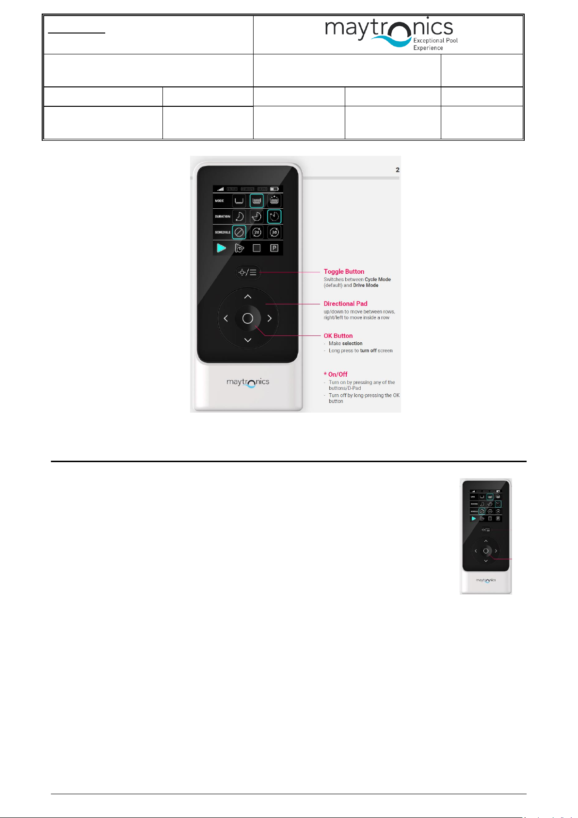
Figure 1 RCU General view
3. Specifications
3.1 Environment
1. Outdoor usage (UV).
2. Working Temperature: -10° - +50° Celsius
3. Storage/Transportation conditions: -20° - +60° Celsius
4. Humidity: 5% - 95%
3.2 Mechanical specifications
1. Artistic design was done by Maytronics and it shall be transfer to contractor
(using SOLIDWORKS 2014).
2. IP67
3. The case plastic material shall be PC.
4. User shall be able to replacement the battery, by using a regular screwdriver opening few screws. After
closing the box, the sealing shall be kept.
5. The display shall have a plastic protection.
6. The unit shall withstand 1-meter fall on concrete.
7. Each button shall withstand minimum 1,000 pressing during its life span.
Figure 2 Artistic design

BLE RCU SERVO CALIBRATION SUPPORT
SOW HW/SW SRS
Date:
Approved By:
Number: Error! Unknown document property
name.
- - R&D Manager:
Page: 9 of 27
Revision: 2.8
- - Project Manager:
Date: 2-Jul-19
Written by: Hagai
Flexer-
All Field will be Fill automatically from the ePDM System.
Page 9 of 27
3.3 HW specifications
1. Display:
a. Icon display (Icons shall be defined in a different document).
b. Active display size 40 mm x 40 mm.
c. Black background.
d. Backlight:
1) The backlight shall be lighted after pushing any button, only in case the power is on.
2) It shall be on for 10 seconds and then turn off.
e. RGB colors.
2. BLE connection to the PWS:
a. Standard: Bluetooth 4.1 and above.
b. It shall be compatibility with the BLE device used in the PWS (Atmel BTLC1000).
c. Operation range: 30 meters from PWS location (ground or caddy), and 360° direction line of sight.
Including RCU holding in different direction (horizontal and vertical towards the PWS).
3. 6 x buttons for selecting modes and for manual navigation:
a. 4 x navigation (straight, backward, left and right)
b. 1 x on & selection & Ok.
c. 1 x Navigation or mode select
4. Buzzer:
a. The RCU shall have a small buzzer. It main purpose is to give sound feedback/acknowledgement
to successful command delivery to the PWS.
b. The buzzer shall make a short, 1 second, sound upon receiving “ACK” message from PWS.
5. On/Off
a. While RCU is off (power off) any button touch shall wake-up the unit i.e. power-up.
b. The RCU shall turn off, automatically, after 30 seconds of no button usage.
6. Power:
a. The RCU shall use 2 pieces of off-the-shelf Alkaline 1.5V AAA size battery manufactured by
Duracell/Energizer or similar.
7. RCU Reliability:
a. RCU life expectancy shall be 5 years.
b. User shall use the RCU about 15 minutes a week (about 1 hour per month).
c. Battery replacement after 3 years i.e. after 40 hours of usage.
 Loading...