

Maytag rh2030, rh2330, rh2036 Instructions Manual
I
I
-
pati No. 6267131883~80 Rev. D
-
3~”
and
36”
Vented
c~st0rn Series
Range Hood
IQ
I-i
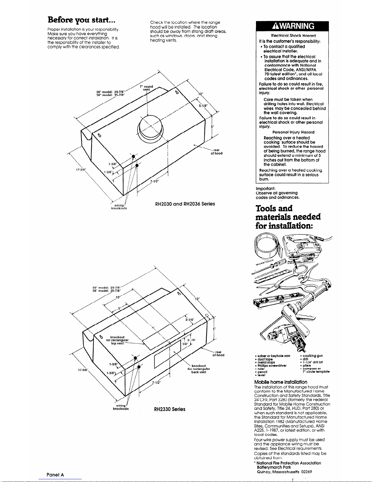
Before you start...
Proper installation is your responsibility.
Make sure you have everything
necessary for correct installation. It is
the responsibility of the installer to
comply with the clearances specified.
Check the location where the range
hood will be installed. The location
should be away from strong draft areas,
such as windows, doors, and strong
heating vents.
knockouts
30” model: 29-7/W
wiring I
knockouts
RH2330 Series
Panel A
Electrical Shock Hazard
It is the customer’s responsibility:
. To contact a qualified
electrical installer.
. To assure that the electrical
installation is adequate and in
conformance with National
Electrical Code, ANSI/NFPA
704atest edition*, and all local
codes and ordinances.
Failure to do so could result in fire,
electrical shock or other personal
injury.
Care must be taken when
drilling holes into wall. Electrical
wires may be concealed behind
the wall covering.
Failure to do so could result in
electrical shock or other personal
injury.
Personal Injury Hazard
Reaching over a heated
cooking surface should be
avoided. To reduce the hazard
of being burned, the range hood
should extend a minimum of 5
inches out from the bottom of
the cabinet.
Reaching over a heated
cooking
surface could result in a serious
burn.
Important:
Observe all governing
codes and ordinances.
Tools and
materials needed
for installation:
l
saber or keyhole saw
l
duct tape
l
metal snips
l
Phllllps rcrewdrlver
l
ruler
l
encll
P l evel
l
caulklng gun
l
drill
l
l-1/4’drlll bit
l
pliers
. compass or
7’ circle template
Mobile home installation
The installation of this range hood must
conform to the Manufactured Home
Construction and Safety Standards, Title
24 CFR, Part 3280 (formerly the Federal
Standard for Moblle Home Construction
and Safety, Title 24, HUD, Part 280) or
when such standard Is not applicable,
the Standard for Manufactured Home
lnstallatlon 1982 (Manufactured Home
Sites, Communities and Setups), ANSI
A225, l-l 987, or latest edition, or with
local codes.
Four-wire power supply must be used
and the appliance wiring must be
revlsed. See Electrlcal requirements.
Copies of the standards listed may be
obtained from:
l
National Fire Protection Association
Batterymarch Park
Quincy, Massachusetts 02269
Electrical
requirements
Venting
requirements
Electrical Shock Hazard
0 Electrical ground is required on this
appliance.
l
If cold water pipe Is interrupted by
plastic, non-metallic gaskets or
other insulating materials, Do Not
use for grounding.
l
Do Not ground to a gas plpe.
l
Do Not modify the power supply
cord plug. If it does not fit the outlet,
have a proper outlet Installed by a
qualified electrlclan.
l
Do Not have a fuse in the neutral or
grounding circuit. A fuse in the
neutral or grounding circuit could
result in an electrical shock.
l
Do Not use an extension cord with
this appliance.
l
Check with a qualified electrician if
you are in doubt as to whether the
appliance is properly grounded.
Failure to follow these instructlons
could result in serious injury or death.
If codes permit and a separate grounding
wire is used, It is recommended that a
qualified electrician determine that the
grounding path is adequate.
A
n A 115volt, 60-Hz, AC-only, fused
electrlcal supply is required. The total
ampere load used, Including the range
hood, must not exceed 90% of rated
capacity of the circuit. The ampere
rating of the range hood is located on
the serial/rating plate located on the
underside of the range hood.
B
n It is the personal responsibility and
obligation of the customer to contact a
qualified electrician to assure that the
electrical installation is adequate and in
conformance with the Natlonal
ElectrIcal Code ANSI/NFPA 70-latest
edition’ and all local codes and
ordinances.
C
w The range hood must be
connected with copper wire only.
D
n The range hood should be
connected directly to the fuse
disconnect (or circuit breaker) box
through flexible armored or non metallic
sheathed copper cable. A U-L,-listed
strain relief must be provlded at each
end of the power supply cable. Wire
slzes (COPPER WIRE ONLY) and
connector must conform with the rating
of the appliance as specified on the
serial/rating plate.
Wire sizes must conform to the
requirements of the National Electrical
Code ANSI/NT-PA 70-latest edition*, and
oil local codes and ordinances.
Fire Hazard
l
Venting system MUST terminate to
the outside.
l
Do Not terminate the ductwork in
an attic or other enclosed space.
l
Do Not use 4” laundry-type wall
caps.
l
Do Not use plastic-type ductwork.
Failure to follow recommended
venting instructions may result in a
fire.
CAUTION: To reduce risk of fire and to
properly exhaust air, be sure to duct
air outside. -
Do Not vent exhaust air
into spaces within walls or ceilings or
into attics, crawl spaces or garages.
Ductwork needed for installation is not
included. Backdraft damper supplied
with product must be properly installed.
If roof or wall cap has a damper, Do Not
use damper supplied with hood.
Determine which outside venting
method needs to be used.
The length of the ductwork and number
of elbows should be kept at o minimum
to provide efficient performance. The
size of the ductwork should be uniform.
Do Not install two elbows together. Use
ductwork system. Ductwork can
terminate either thought the roof or wall.
Use caulking to seal exterior wall or roof
opening around exhaust hood, For the
most efficient and quiet operation, it is
recommended that the range hood be
vented vertically through the roof
through 7” round ductwork.
Flexible metal ductwork is Not
recommended.
If it is used, calculate
each foot of flexible metal ductwork as
two feet of straight metal ductwork.
Flexible metal elbows count twice as
much as standard elbows. Use metal
ductwork only.
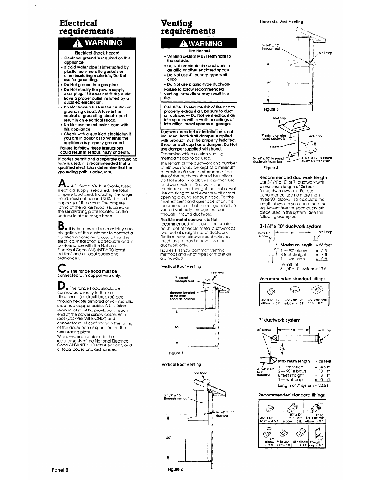
Figures l-4 show common venting
methods and what types of materials
are needed.
Vertical Roof Venting
roof cap
damper located
as far from
hood as possible
Figure 1
Vertical Roof Venting
roof caD
3-l/4’ x 10’
through the roof
Horizontal
Wall Venting
Figure 3
7’ mln. diameter
round ductwork
wall cap
J-1/4” x 1O’to round
ductwork transltlon
Figure 4
3-l/4’ x 1O’to round
ductwork trandtlon
Recommended ductwork length
Use 3- l/4” x 10” or 7” ductwork with
a maximum length of 26 feet
for ductwork system. For best
performance. use no more than
three 90” elbows. To calculate the
length of system you need, odd the
equivalent feet for each ductwork
piece used in the system. See the
following examples.
3- l/4” x 10” ductwork system
3Yi'
x IO”
elbow
/p--- 6ft.----
wallcap
7 Maximum length = 26 feet
6”:
t2n. 1
- 90’ elbow
4 8 feet stralght
= 5ft.
= 8ft.
I
1 -wall cop
= oft
-.
Length of
3- l/4’ x 10’ system = 13 ft.
Recommended standard fittings
I 1
I
3Y4” x IO” 90” 3Y4” x iO’* flat ’ 3Y4” x IO” wall
elbow = 5 tt. elbow = 12 tt caD = 0 ft.
J
7” ductwork system
90' elbow
wallcap
Maxlmum length
= 26
feet
fiv”’ ’ ‘O’
1 -transition = 4.5 ft.
2
- 90’ elbows
=lO ft.
transltlon
8 feet straight = 8 ft.
1 -wall cap = 0 l=t,
Length of 7’ system = 22.5 ft.
Recommended standard fittings
3Y4” x lo"
I
3Y4” x lo”
to 7” 90’
3Y4” x 1s &
to7” = 4.5n. elbow = 5
n.
elbow = 9tt.
8 @ CP
elb%
8,
7” to 3Y4” “.! 4,
Elbow 7”wgll*’
= 5n.
Xlo”=ltt.
= 2.5
n.
cap= 0 tt.
Panel B
Figure 2
 Loading...