

Maytag MFR30PNCTS, MFS230PTVS, MFS230PTRS, MFS230PAVS, MFS230PARS Installation Instructions
...Page 1
FULL CONTROL
COMMERCIAL WASHER
PROGRAMMING GUIDE
(North America Only)
Table of Contents ..................................................................................................................2
321
654
987
0
W10214576D
www.maytagcommerciallaundry.com
Page 2

TABLE OF CONTENTS
WASHER SAFETY ............................................................. 3
CONTROL PANEL ............................................................. 4
Control Panel Overview ...................................................4
Keypad ........................................................................... 4
How to Enter Program Mode ......................................... 5
Main Menu ...................................................................... 6
GENERAL CONTROL DESCRIPTION ..............................7
Control Features ............................................................. 7
Menu Functions .............................................................. 7
Machine Types ............................................................... 8
Create a Wash Program ................................................. 8
Program Functions ......................................................... 9
WASHER STARTUP ........................................................ 11
Conguration Menu ...................................................... 11
Advanced Menu ........................................................... 15
Initialization Menu ......................................................... 18
Wash Program Creation and Adjustment .....................20
CYCLE PROGRAMMING ................................................ 21
Program Menu .............................................................. 21
Program Functions ....................................................... 21
Program Step Function ................................................ 22
Program the Wash Cycle ............................................. 23
Program the Drain Step ................................................ 33
OPERATION ..................................................................... 36
Start a Laundry Load .....................................................36
Cycle Options ................................................................36
Program End and Unloading ........................................ 37
Messages During the Wash Cycle ............................... 37
Special Function Keypad ............................................. 38
PROGRAMMED CYCLES ............................................... 39
Legend .......................................................................... 39
WASH PROGRAMS ......................................................... 40
TROUBLESHOOTING ..................................................... 47
Display Messages ........................................................ 47
Fault Code Overview .................................................... 49
Service Menu ................................................................ 52
Problem Check List ...................................................... 57
Error Message Explanation .......................................... 58
SERVICE INFORMATION ............................................... 83
Replacing the Electronic Board and Keypad ............... 84
Installing New Software ................................................ 84
Washer Specications .................................................. 85
APPENDIX ........................................................................ 86
Table A-1: Conversion Between
Celsius and Fahrenheit ................................................. 86
Table A-2: Conversion Between
Kilograms and Pounds ................................................. 86
Table A-3: Machine Conversion ................................... 86
Table A-4: Maximum, Minimum, and
Normal Water Setting Values ....................................... 87
Table A-5: Programmable Water Level Units
Related to the Amount of Water in the Tub ................. 88
Table A-6: Washer Wash and Spin Speeds ................ 91
2
Page 3
WASHER SAFETY
3
Page 4
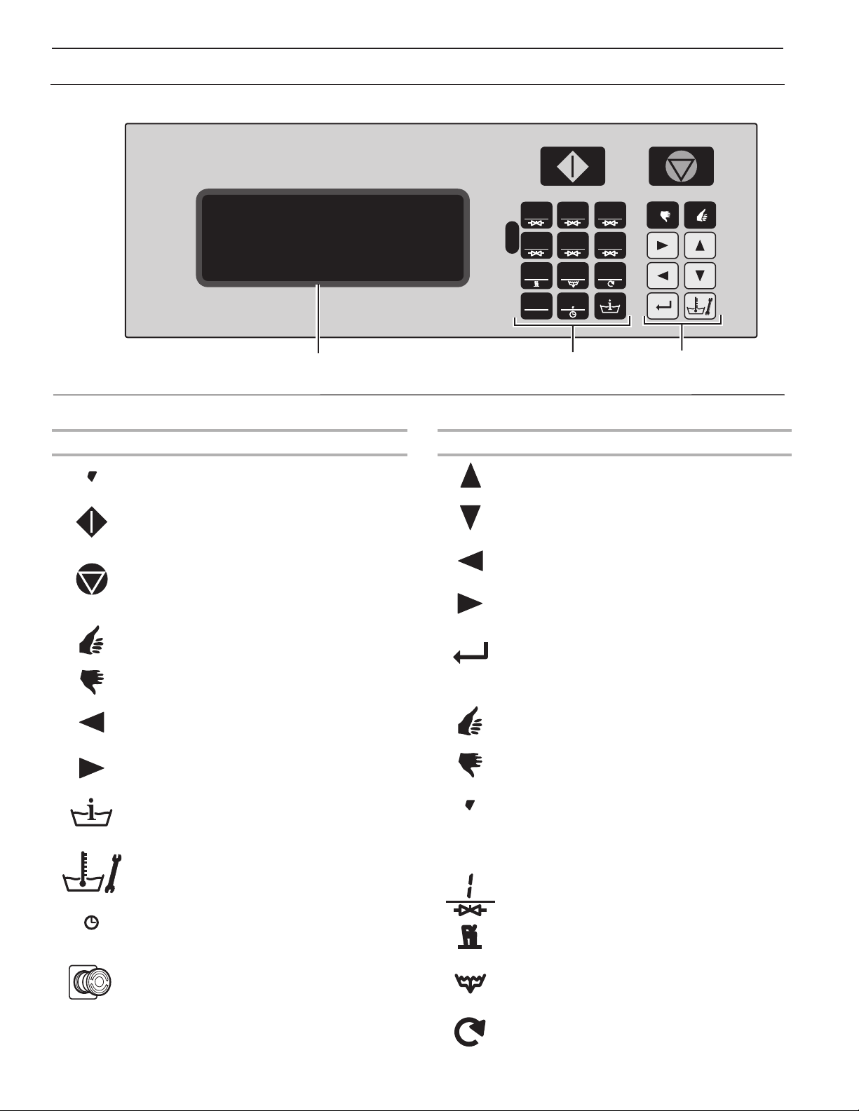
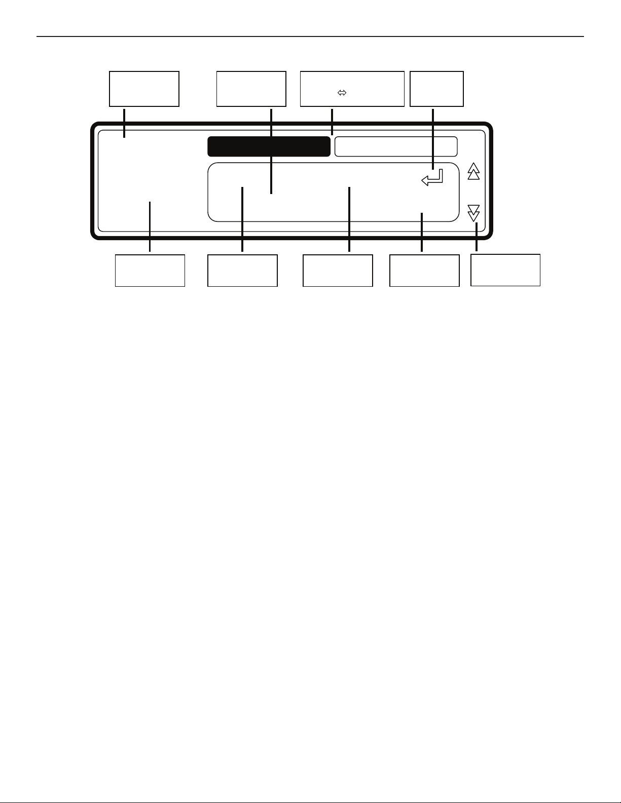
CONTROL PANEL
Control Panel Overview
0
321
654
987
LCD Display
Operation
Keypads
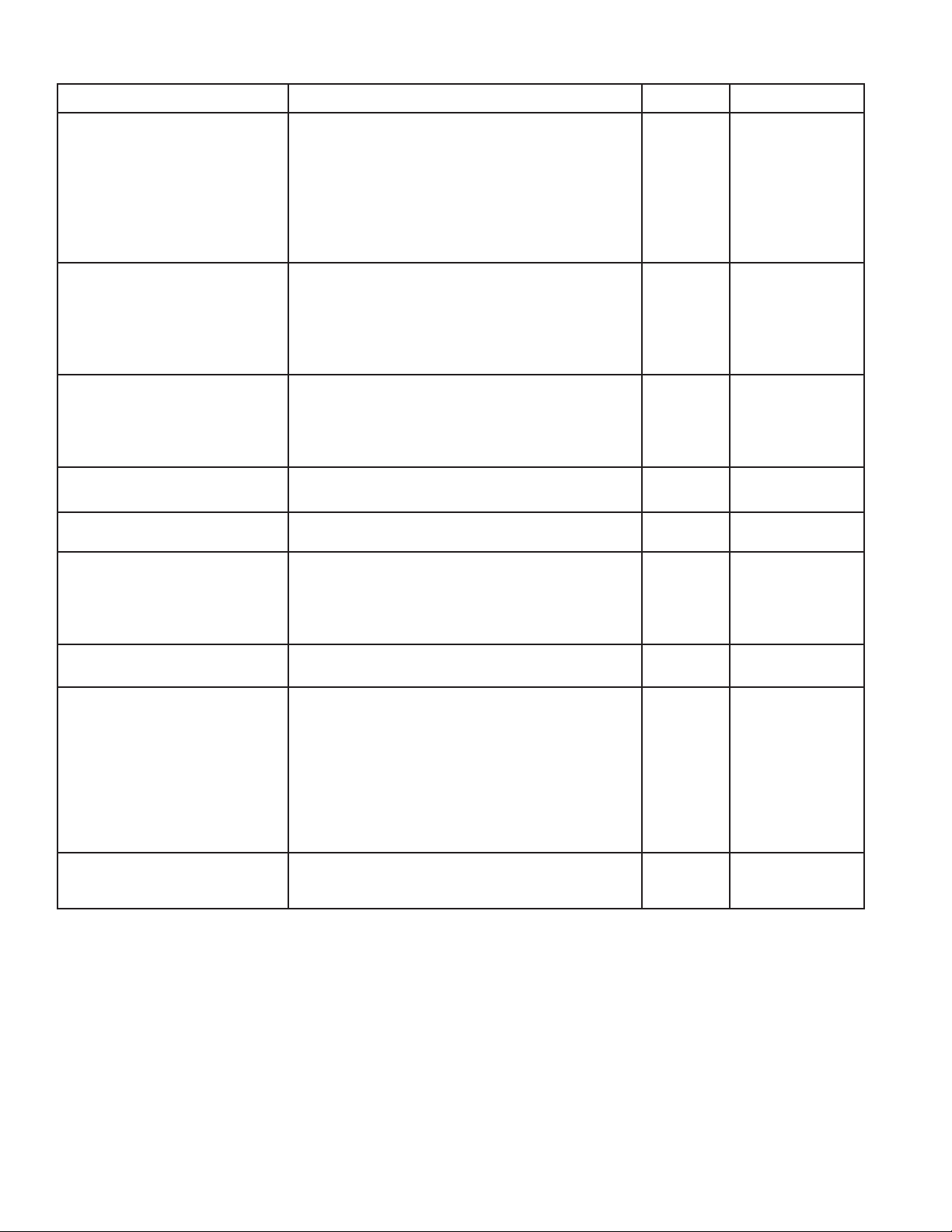
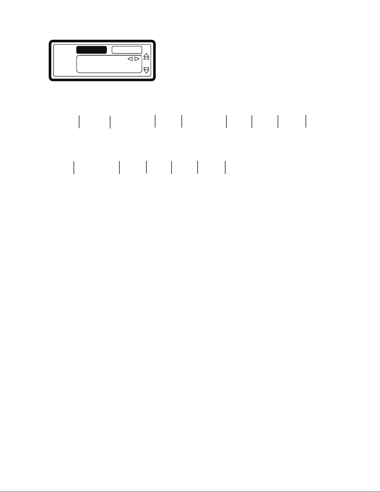
KEYPAD
Operation Keypads Program Keypads
n 1 2 3 4 5 6 7 8 9 0
- Program number selection keypads
n START
- Starts a program
- Advances the program step by step
n STOP
- Interrupts a program
- Ends a program
n YES
- Select displayed option
n NO
- Do not select displayed option
n ARROW LEFT
- Decreases the sequence time
n ARROW RIGHT
- Increases the sequence time
n ARROW UP
- Selects the previous menu item
n ARROW DOWN
- Selects the next menu item
n LEFT ARROW
- Selects the previous element of a menu item
n RIGHT ARROW
- Selects the next element of a menu item
n ENTER
- Selects a new menu
- Conrms a new value or list element and
continues to the next menu item
n YES
- Select displayed option
n NO
- Do not select displayed option
Program
Keypads
n INFO
- Shows all available wash programs, program
steps and functions
n SERVICE/STATUS
- Shows the status and total number
of washer cycles
n 1 2 3 4 5 6 7 8 9 0
- Numeric values
- Decimal point
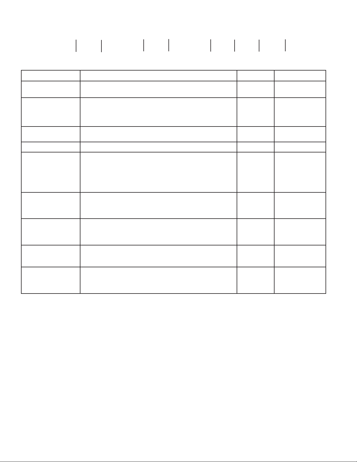
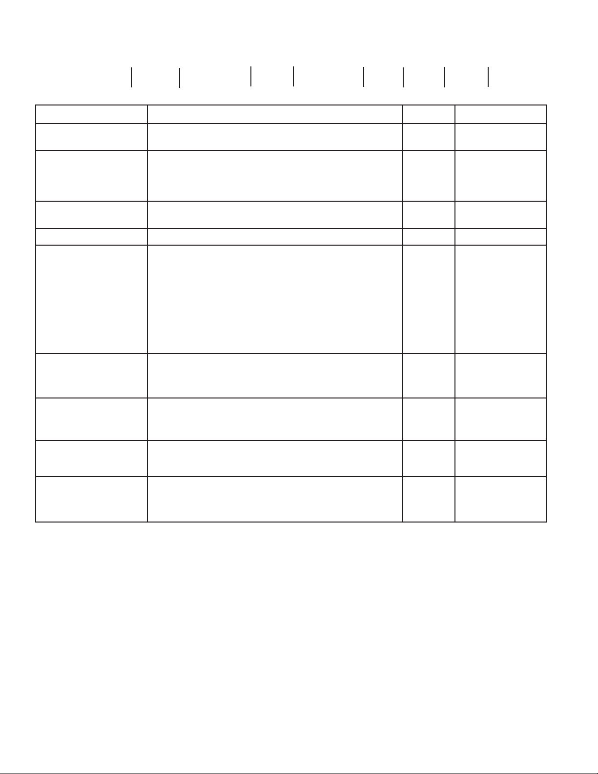
SPECIAL FUNCTION KEYPADS
n INLET 1 2 3 ( 4 5 6 )
- Opens the inlet valve
n DELAY TIME
- Activates the time delay function
n HEAT
- Activate the heat (if equipped)
EMERGENCY STOP SWITCH
This emergency stop switch is used on non-coin
washer-extractors. Located on the control panel
n DRAIN
- opens the drain valve
just left of the LCD Display
n SPEED ADJUST
- Adjusts the spin speed in a cycle
4
Page 5
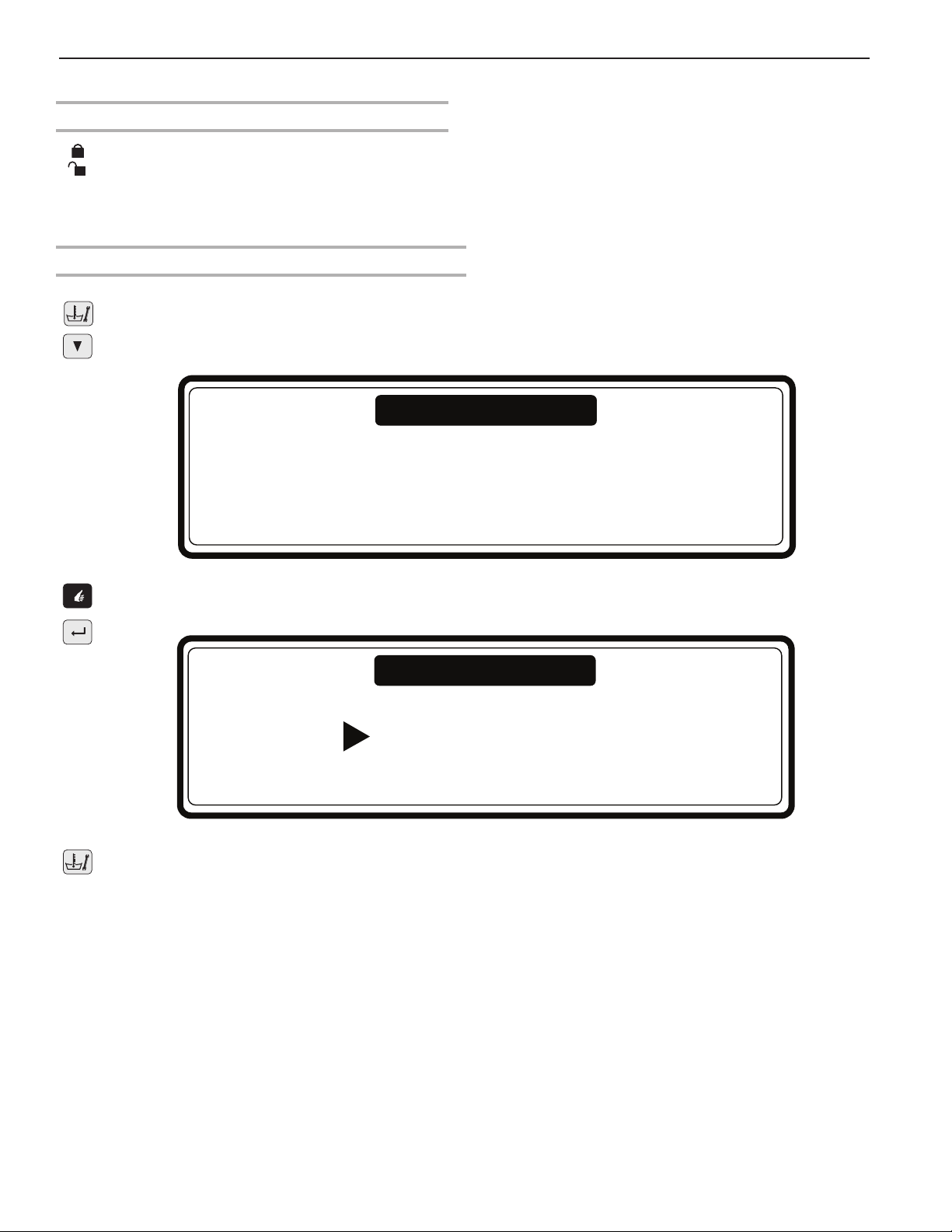
How To Enter Program Mode
To Enter With Keyswitch
KEYSWITCH
The key switch may be mounted on the front panel, the rear panel, or in the control area of the washer.
With the key switch you can select “Run Mode” or “Program Mode”
– RUN MODE: For normal washer wash operation.
– PROGRAM MODE: For changing the wash programs and washer settings.
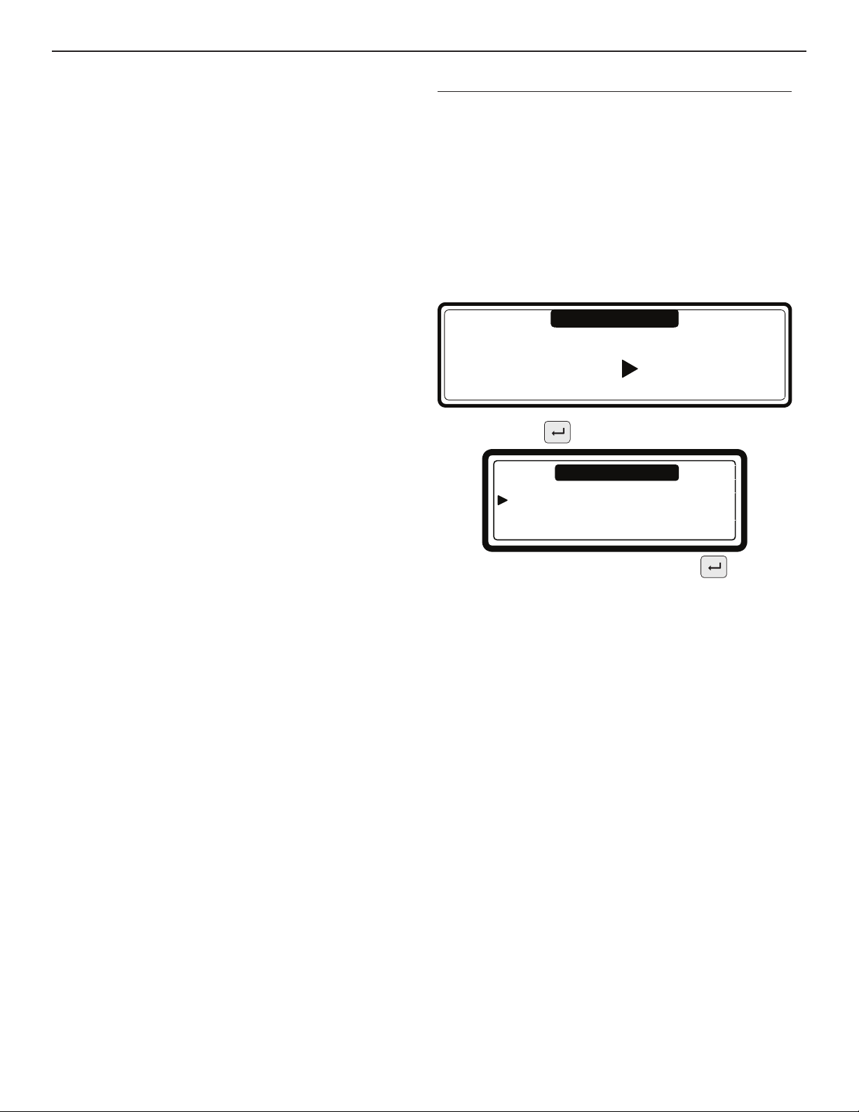
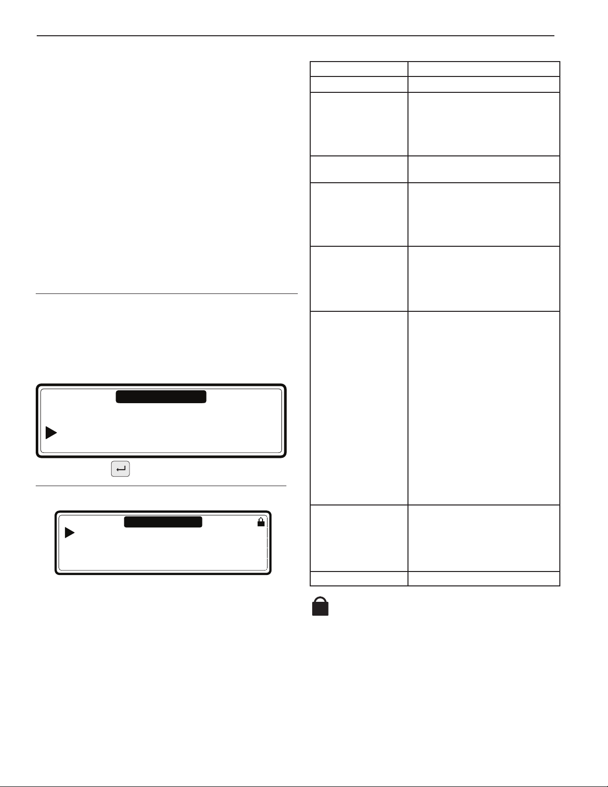
To Enter With Program Keypads
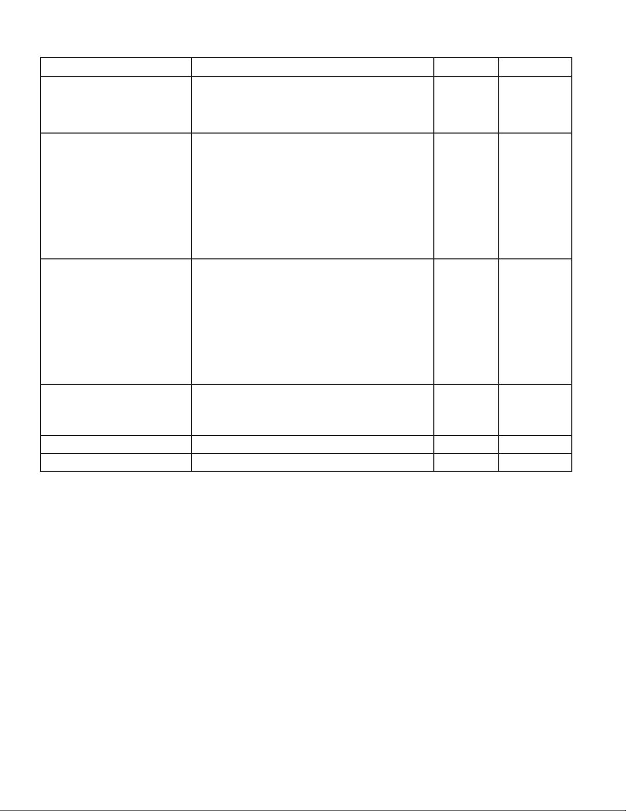
1. Press Service/Status.
2. Press Arrow Down several times until you see the screen with the menu selection “To Program
Mode No/Yes.”
Status Menu
To Program Mode No/Yes
3. Select “Yes” by pressing ENTER. You will see the Main Menu Screen. If a password was enabled, rst you have to
enter the correct password.
To Program Mode
Password ....
To leave the To Program Mode:
When the “Main Menu” screen is shown:
Press Service/Status. You will return to “Run Mode” and “SELECT CYCLE” is displayed.
5
Page 6
8
Initialization Menu
Program Menu
Service Menu
1.
1.
Conguration Menu
Initialization Menu
Program Menu
Service Menu
Conguration Menu
8 8 8
Advanced Menu
Advanced Menu
Data Acquisition Mem
Hygienic Cycle
Strict Temp. Control: NO
Temp. Calib. Offset: 0
Program Mode Lock
Conguration Menu
Machine Type R6 tu
Reset Defaults ?
Brightness Display: 12
Inverter Menu
Password 3 2 1
2.
Password
Edit Password
New Password
Old Password
Supply Volt: 3x380-415V+N tu
Load Param
Steam Connect: NO
Total N of Inlets: 2 tu
No Password
Program Lock
Password
Programs
Drain Valve 2: NO
(Water Recycle Inlets: 0) tu
Supply Sign A: Box tu
Supply Sign B: Box tu
Program 1 Unlocked tu
Edit Password
New Password
Old Password
Supply Sign C: Box tu
Supply Sign D: Box tu
Supply Sign E: Box tu
Liquid Soap Supply: NO
No Password
Traceability:
Enable Traceability: NO
Traceability Report: Store DAQ tu
Weighing
Min. Level Start Supply: 0
Temperature: Celsius tu
Full Heating: 67
Wet Cleaning: NO
Erase All Wash Program
Weighing System: NO
Main Units: kg
Help Units: %
Load Cell Calibration
Expected Free Weight: XXXX
Water Level: Units
Automatic Level Adjust: NO
(Automatic Soap Adjust.: NO)
Advance Menu Exit
Load Standard Programs
Language: English tu
Load Program 1 - 15? NO
Load Program 16 - 52? NO
Advanced Menu: NO
Conguration Menu Exit
Communication Type: RS485 tu
Communication Address: 1
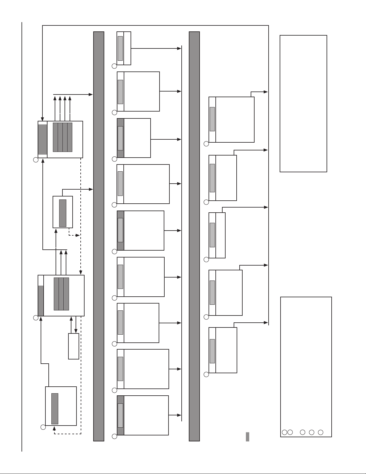
Change the Settings at the Menu items.
Select the Initialization, Program, Service or Conguration Menu.
1.
8
2.
MAIN MENU
Initialization Menu
1.
Initialization Menu
1.
Program Menu
Service Menu
Conguration Menu
8
Program Menu
Service Menu
Conguration Menu
8
Service Menu
Software Y Y Y Version: X.XX
Diagnostic Program
Start Cycle: NO
Faults
2.
View Fault Messages
8
Program Menu
See Corresponding owchart
How to Create and Adjust
2.
a Wash Program
View Fault Messages: NO
View Fault Statistics
Toolbox
View Input States
Invert Power: Off
Pulley Ratio: XX
Reset Service Counts: NO
8
(RTC Time: XX: YY: ZZ)
(RTC Date: AA: BB: CC)
(Adjust Clock)
Service Menu Exit
8
p Selecting the Menu item: Press UP or DOWN.qtu Selecting list: Press LEFT or RIGHT.
8 Selecting a new program Sub-menu and go to the next item: ENTER.
8 Conrming a menu item and go to the next menu item: ENTER.
-- Insert a value or Select another List element.
Attention !!!
Depending the Machine Type,
Initialization Menu
Program Menu
Service Menu
1.
Conguration Menu
Initialization Menu
Language English tu
Service Interval: 3000
Buzzer time: 5 sec
2. 2.
Allow Advance: YES
Automatic Cool Down: YES
Wait for Temperature: YES
Manual Override: YES
Temperature balance: YES
Motor On Time: 12 sec
Motor Off Time: 3 sec
Smart Motion: YES
Hot Water Heater temp. 60 °C
Keyswitch: Program
Temp Overshoot Protection: -00%
Max, Heating Time: 60 Min
Max, WaterFill Time: 10 Min
Overll Detection: 10 Units
External Wait Control: NO
Main Water Pressure: High tu
Initialization Menu Exit
some items will not be displayed.
6
Page 7

GENERAL CONTROL DESCRIPTION
Control Features
The control offers:
n 99 programmable cycles
n 15 pre-programmed cycles and 37 dedicated programs
n Signal voltage control for external pumps or liquid supply
dispensers
n Redistribution of garments, if needed, to reduce vibration
during extraction
n Automatic temperature control during the water ll process
n Wash options and conguration setting
n Language (English, French, or Spanish)
Information displayed during operation:
n Program selected
n The active wash step
n The remaining program time
n Wash cycle progression bar
n The name of the sequence
n Indication of wait for heat (if selected)
n Symbol for water lling
n Symbol for heating
n The water level and temperature can be viewed
n Diagnostic messages
Operation Menu:
n Manually shorten, extend, or stop a cycle
n Pause a cycle
n Special function keypads allow direct operation of
selected components (water valves, etc.)
n Program overview
n Service information
THE HARDWARE AND SOFTWARE OF THE FULL
CONTROL WASHER CONTROLLER:
n Easy operation using a comprehensive keypad
n The hardware contains 1 electronic board
n The MCG FC washer controller with Graphic LCD display
n Washer control software is stored as Flash memory
that is easily replaced
n Washer programs are stored as EEPROM memory
(non-volatile memory)
Menu Functions
The PROGRAM Menu allows you to:
n Create and name wash programs
n Edit existing wash programs
n Modify wash programs
n Copy wash programs
n Delete wash programs
n Inspect wash programs with the VIEW function
The CONFIGURATION Menu allows you to:
n Select the Machine Type
n Load the default factory settings into the CONFIGURATION
and INITIALIZATION Menu
n Select the display brightness
n Select the power supply voltage of the washer
n Load the Frequency Inverter Parameters
n Erase all the programmed wash programs
(reset Wash program in EEPROM memory)
n Load the standard wash programs
n Select the number of washer water supply inlets
n Select a second drain valve for water recycling
n Select Soap Box or liquid supply
n External liquid pump setup (if connected)
n Select the temperature display (Celsius or Fahrenheit)
n Select full heating
n Low water pressure setting
n Select wet cleaning option
n Select the minimum water level for chemical supply to start
The INITIALIZATION Menu allows you to:
n Select display language
n Program the Service due cycle count
n Set buzzer time interval
n Select/deselect the Advance function
n Select/deselect the Wait for temperature function
n Select/deselect allow manual override of a step or
function
n Select/deselect the Temperature balance function
n Select/deselect the default speed and reset time of wash
cycle action
n Select/deselect the Automatic Cool Down function
n Select/deselect the Show Economic function
n Program the hot water supply temperature
n Program the Temperature Overshoot Protection
temperature
n Program the Maximum Heating Time
n Program the Maximum Fill time
n Programming the Maximum Level Overll value
The SERVICE Menu allows you to:
n Inspect the error messages log register and statistics
n Activate the power of the Frequency Inverter
n Determine the functionality of the electric input signals
n Reset the Cycle counter
The DIAGNOSTIC Menu runs a diagnostic cycle to detect
problems with the washer
The ADVANCED Menu is designated for special optional
applications and is available on Model MFS55 and larger
models.
7
Page 8
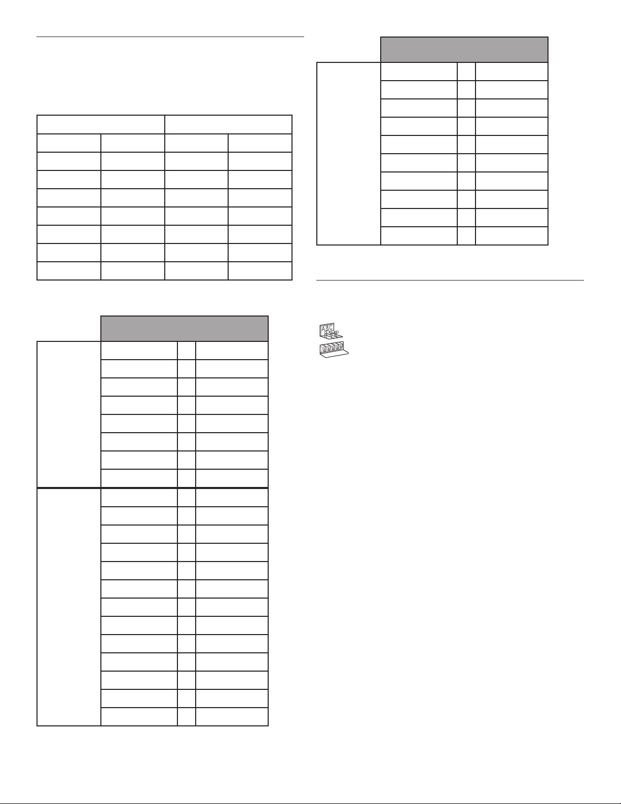
Machine Types
This programming guide uses Machine Types for references to
the tables and text. Refer to the table below for Machine Types
for your washer.
Machine Types Used for Commercial Washers
Rigid Mount Washers Soft Mount Washers
Model Machine Type Model Machine Type
MFR30PNCTS R 13 MFS25PNFTS F 10
MFR40PNCTS R 18 MFS35PNFTS F 16
MFR60PNCTS R 27 MFS55PNAVS F 23/3
MFR80PNCTS R 35 MFS50PNFVS F 22
- - MFS80PNFVS F 33
- - MFS100PFVS F 40
- - MFS125PFVS F 55
Machine Type Selection for Commercial Washers
Dry load “Machine Type”
capacity selection
6 kg / 15 lbs => R6
7 kg / 18 lbs => R7
Rigid
mounted
industrial
washer
extractors
Soft Mount
industrial
washer
extractors
10 kg / 25 lbs => R10
13 kg / 30 lbs => R13
18 kg / 40 lbs => R18
22 kg / 50 lbs => R22
27 kg / 60 lbs => R27
35 kg / 80 lbs => R35
6 kg / 15 lbs => F6
7 kg / 18 lbs => F7
10 kg / 25 lbs => F10
13 kg / 30 lbs => F13
16 kg / 35 lbs => F16
22 kg / 50 lbs => F23/3*
22 kg / 50 lbs => F23/4**
33 kg / 80 lbs => F33
40 kg / 100 lbs => F40
55 kg / 125 lbs => F55
80 kg / 180 lbs => F800
100 kg / 225 lbs => F1000
120 kg / 275 lbs => F1200
Dry load “Machine Type”
capacity selection
16 kg / 35 lbs => MB16
26 kg / 60 lbs => MB26
33 kg / 80 lbs => MB33
Soft Mount
hygienic
44 kg / 110 lbs => MB44
66 kg / 150 lbs => MB66
barrier
washer
extractors
70 kg / 160 lbs => MB70
90 kg / 200 lbs => MB90
110 kg / 245 lbs => MB110
140 kg / 310 lbs => MB140
180 kg / 400 lbs => MB180
NOTE: Other Machine Types appear in the software, but do
not correspond to current Maytag brands.
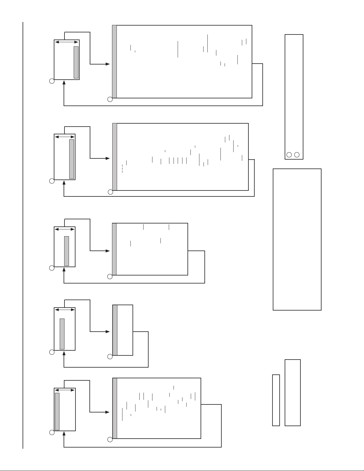
Create a Wash Program
n The Full Control washer controller is designated for:
Washers with a top dispensers.
Washers with front/side dispensers.
E
D
C
B
A
n Wash programs are built step-by-step.
n Each step consists of a Wash Sequence and a
Drain/Extraction sequence.
n 99 wash programs with 99 steps is programmable.
Programming the Wash Sequence:
n First choose the type of Wash Sequence.
Washer with
Top Soap Dispenser
n Prewash
n Wash
n Cool Down
n Rinse
n Final Rinse
n Flush
n Soak
n Spray
n No Wash
Front/Side Soap Dispenser
n Wash
n Cool Down
n Rinse
n Soak
n Spray
n No Wash
Then program all the related functions of the sequence.
The available functions are:
n Temperature
n Water Level
n Water Inlet Valves
n Wash Speed
n Reversing Interval times
n Supplies
n Sequence Time (length of step)
n Drain Valve 1–2
n Pause Signal
Each step has default settings. Many new programs will
not require changes from the suggested values.
Washer with
* Washers with plastic soap dispenser
** Washers with stainless steel soap dispenser
8
Page 9

Programming the Drain sequence:
After programming the Wash Sequence, program the
Drain/Extraction sequence.
n Drain, or
n Extraction, or
n No Drain, or
n Static Drain, or
n Reversing Drain.
Then program all related functions of the Drain/Extraction
sequence. The available functions are:
n Sequence Time (length of step)
n Speed
n Drain valve 1–2
It is also possible to skip a sequence between two other
sequences by programming No Wash or No Drain.
Example: The No Drain sequence should be programmed
between a Wash and a Cool Down Sequence.
NOTE: See Programming for more information on sequences.
Tumble Sequence:
n The wash cycle always ends with a Tumble Sequence.
n The Tumble sequence takes 30 seconds, then the program is
nished and the door can be opened.
n The Tumble sequence cannot be skipped.
Program Functions
Limits:
n To ensure the correct operation of the washer, values must be
within certain limits.
n Programming functions into a washer that does not have the
associated function will cause error codes during operation.
n If a programmed value is outside the programmed limits, the
default program value will override the programmed value.
The hot water inlet valves
Inlet Valve 4 Corresponds with Soap Box B (Wash).
Inlet Valve 3 Is a direct inlet valve and speeds up the
water ll process.
See the schematic diagram supplied with the washer for
additional information on inlet valves.
How to Select Inlet Valves:
EXAMPLE:
n For a Prewash: Programmable temperature: 34–113°F
(1–45°C)
Inlet Valve 2 (cold) Soap Box A
+ Inlet Valve 3 (hot)
and/or 6 (cold) Direct Inlets
n For a Wash: Programmable temperature: 34–198°F
(1–92°C)
Inlet Valve 4 (hot)
and/or 5 (cold) Soap Box B
+ Inlet Valve 3 (hot)
and/or 6 (cold) Direct Inlets
n For a Rinse: Inlet Valves 2 + 5 + 6 (cold) No Soap
n For a Final Rinse: Inlet Valve 1 (cold hard)
(or cold soft) Soap Box C
+ Inlet Valve 6 (cold soft) only if No
NOTES:
n Water inlets 3 or 6 must be used for washers with laundry
product supply pumps because the liquid is added at the
direct water inlet channel.
n Depending on the washer, cold water can be used with water
Inlet Valve 1.
n If the water recycling feature is used, the water recycling
supply must be connected to Inlet Valve 2 or 5.
Programming the Water Temperature:
– Minimum value: 34°F (1°C)
– Maximum value: 113°F (45°C) for PREWASH and SOAK,
and 196°F (92°C) for the WASH Sequence.
– For RINSE, FINAL RINSE, FLUSH, and SPRAY, no
temperature can be programmed.
Programming the Water Inlet Valves:
n Depending on the programmed temperature the water inlet
valves are suggested.
n While the tub is lling with water, the computer controls the
water temperature by switching on and off the hot and cold
water inlet valves.
n For washers with a Top Soap Dispenser, you must consider
that by programming the water inlet valves, you are also
selecting the Soap Box at which the soap must be added.
n If you want to program a Wash Sequence with:
– Cold water: Only cold inlet valves must be programmed.
– Warm or hot water: Cold and hot inlet valves must be
programmed.
Top Soap Dispenser washers:
The cold water inlet valves
Inlet Valve 2 Corresponds with Soap Box A (Prewash).
Inlet Valve 5 Corresponds with Soap Box B (Wash).
Inlet Valve 1 Corresponds with Soap Box C (Final Rinse).
Inlet Valve 6 Is a direct inlet valve and speeds up the
water ll process.
9
Page 10

Front/Side Soap Dispenser washers:
The cold water inlet valves
Inlet Valve 1 Cold Hard Water or Recycled Water
Inlet Valve 2 Cold Soft Water
The hot water inlet valves
Inlet Valve 3 Warm Soft Water
NOTE: To add soap to a Front/Side Soap Dispenser washer,
the supplies must be programmed.
Programming the Water Level:
Water level Limits
n See “Water Setting Values for Different Washers” because
these values are different for each Machine Type.
n The minimum value is above the heating elements and the
temperature sensor
n The maximum value is below the overow outlet
Normal Low Level, Normal High Level
n The Normal Low Level is recommended for the PREWASH,
WASH, and SOAK sequences.
n The Normal High Level is recommended for the RINSE and
FINAL RINSE Sequences.
n At the FLUSH sequence, you can’t program a water level
because the water will escape through the overow opening.
n At the Cool Down sequence, the Full Control washer
controller makes use of a low water level and is draining
the water automatically.
n At the Spray sequence, the Drain valve stays open.
Economic Water Level
n If you prefer a wash cycle with an economic water level:
You can select “Show ECONOMIC” in the Initialization
Menu to use the standard setting.
n ECONOMIC function. At the start of each wash cycle,
the question ECONOMIC? will be displayed. If you select
ECONOMIC, the program will function with 20% units less
water.
– or you may make dedicated programs with a water level
20% units below the normal water level.
Wet Cleaning selection Conguration Menu
n It is possible to program a level below default minimum
programmable level. (See table on page 87).
n The heating will not be functional for a water level below
the standard minimum programmable water level.
NOTES:
n Normal high water level is recommended for woolens
and delicate linens.
n The economic function should only be used for small,
lightly soiled wash loads.
Programming the Wash Speed:
n Standard reversing Wash Speed is between 40 and 50 RPM
(See table on page 91).
n For some special applications the drum should only turn very
slowly.
Speed Limits:
n The minimum programmable Wash Speed is 10 RPM.
n The maximum programmable Wash Speed is 40 - 60 RPM,
depending on washer size.
Programming Extraction Speed:
n See Table A-5 for maximum and minimum spin speeds. The
limits differ depending on the maximum allowed g-force at
high spin for each Machine Type.
n An Intermediate spin between two sequences should be about
1/2 the maximum spin.
Programming Supplies:
n Up to 4 supplies can be programmed at the same time in a
sequence.
n For Front/Side Soap Dispenser washers, supplies A, B,
C, D, and E have to be programmed to inject the soap by
compartment.
n If liquid soap pumps were installed on the washer, these
pumps will be activated by programming a time value for the
corresponding supply signal 1, 2, 3, 4, 5, 6, 7, or 8.
n The maximum programmable time is 99 seconds per
sequence.
n If the time is 0 seconds then the supply will NOT be
activated during the wash process.
NOTE: If more than 4 supplies are needed in the same step, run
the step twice with half the water volume in each step. Use the
NO DRAIN sequence between the steps so the water does not
drain out.
Programming the Motor On and Off Times
for Reversing
n The default Reversing Motor On and Off Times at Wash Speed
is 12 seconds on and 3 seconds off.
n For Delicates and Woolens, it is recommended to program a
Gentle Wash action with a On time of 3 seconds and an Off
Time of 12 seconds.
Programming the Sequence Time
n The sequence time starts running after the programmed
water level is reached.
n If the Wait for Temperature feature is selected, the
sequence time begins only after the programmed
temperature is reached.
NOTE: The Wait for Temperature feature must be Off unless
there is an auxiliary heat source on the washer.
n For a Cool Down Sequence, the programmed time
corresponds with the time for decreasing the water
temperature.
TIP: A cool down of 3 minutes must be programmed. To avoid
garment shrinkage, it is recommended to program the time
so that the temperature will decrease with about 5°F (3°C)
for each minute.
Buzzer
n The Buzzer should be programmed when a running wash
cycle needs to be interrupted.
n The Buzzer will be activated to alert the operator.
n In most cases, the operator interrupts a program to ll
the Soap Box an additional time.
n The program interruption will always occur at the end of
a step.
10
Page 11
WASHER STARTUP
Perform washer startup after the washer is installed. See the
Installation Instructions for your washer. Startup consists of
three steps:
n Select the washer specic settings in the Conguration
Menu.
n Select the operator specic settings in the Initialization
Menu.
n Adjust default programs or create new programs at the
Program Menu.
Initial conguration and initialization settings were done at
the factory.
IMPORTANT:
n Read this manual thoroughly before making changes to
the Conguration or Initialization Menus.
n Write down current settings before changing any setting.
n The default washer setups are used for a wide variety of
models and applications. Some program modications
may be necessary to achieve optimum performance for
your application.
Configuration Menu
The Conguration Menu allows you to choose individual
washer specic settings. The Conguration Menu can only be
accessed when the washer is in standby mode.
IMPORTANT: Only a qualied technician should perform
conguration setup. Incorrect conguration setting could
cause serious washer damage.
1. Make sure power is ON and no program is running.
2. Turn the key switch to PROGRAM MODE or enter through
the Program Mode setup with the keypad sequence outlined on page 6. The Main Menu will be displayed.
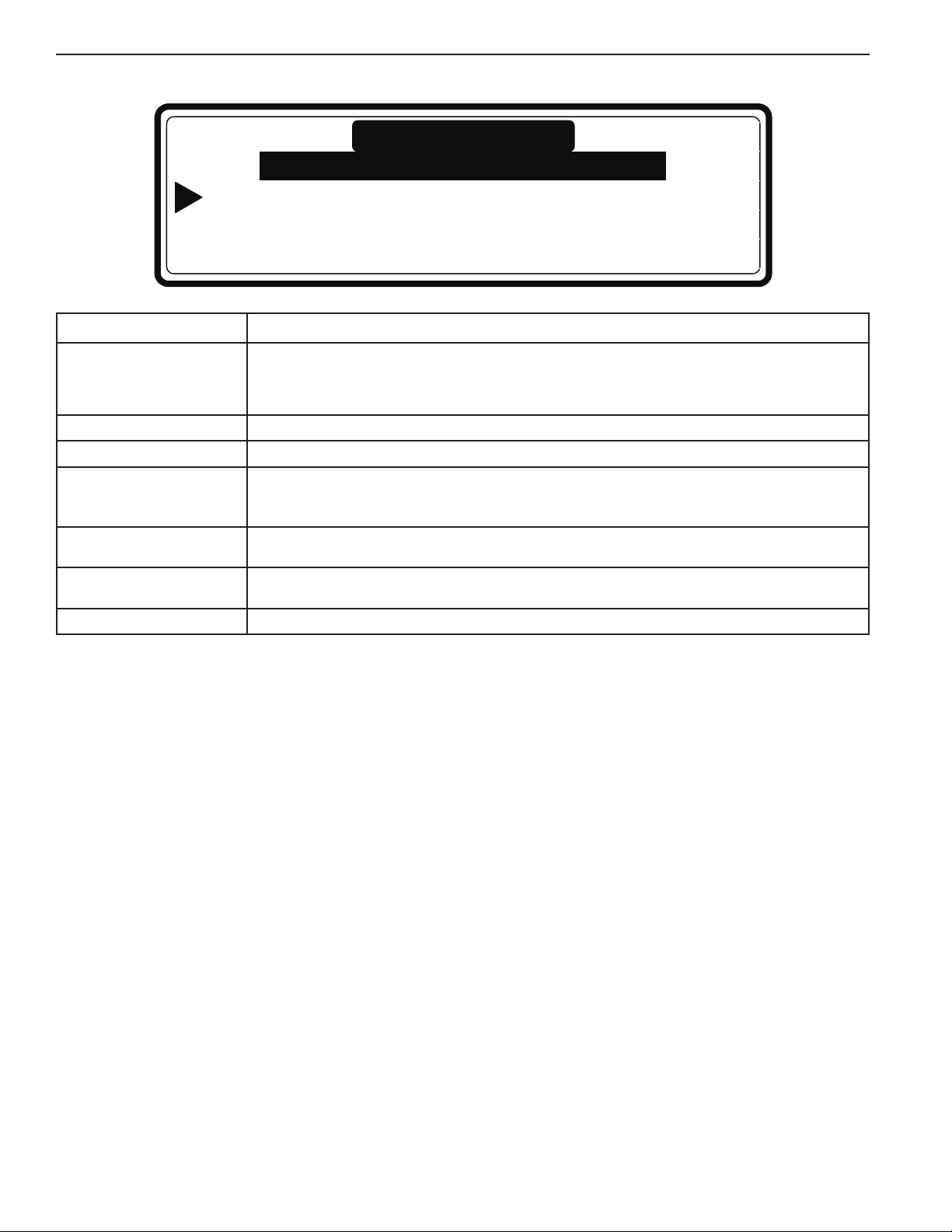
3. Press 5 or 6 to select the Conguration Menu.
Main Menu
Initialization Menu …
Program Menu … Configuration Menu …
Service Menu … Advanced Menu …
4. Press ENTER.
The password screen will appear.
Configuration Menu
Password _ _ _
5. Enter the password “3-2-1”. Press ENTER.
6. Press 5 or 6 to select the menu items individually.
11
Page 12

Conguration Menu Options and Defaults
Menu Item Description Default Range
Machine Type
Are You Sure ?
Reset Defaults ?
Are You Sure ?
Brightness Display Change the display brightness for best viewing. 12 1–20
Inverter Menu…
Select the Machine Type. The Machine Type is on
the Name Plate at the rear of the washer.
Conrm that you want to change the Machine Type.
(F23/3 = Top Soap Dispenser)
(F23/4 & F22/5 = Front/Side Soap Dispenser)
NOTES:
Changing the Machine Type does not change wash
programs stored in EEPROM memory. Erase all
program memory and the standard wash programs
again after changing the Machine Type because
wash programs settings differ for each washer.
To ensure proper operation, make certain the
Machine Type is correct. See table on page 86.
Resets Initialization and Conguration Menu settings
to the default factory settings.
Only used at SETUP of a new washer controller.
Conrm that you want to Reset Defaults.
Loads the Inverter Menu.
NOTES:
The washer can only perform properly if the Inverter
Parameters are correct. Make certain the Inverter
Type and supply voltage are correct.
Not for washers R6, R7, R10.
R6
No
No
No
List
No/Yes
No/Yes
No/Yes
Supply Voltage XXXXXXX
(Inverter Type)
Load Param…
Are You Sure ?
Steam Connect Not valid for washers MFS18 to MFS35, MFR18 to
* Choices vary by model.
Select the correct supply voltage as indicated by
the washer nameplate.
NOTE: Loading parameters is only required after
Inverter replacement or if there are problems with
the drive system.
n Conrm that you want to load the Inverter
Parameters.
If yes:
– Door must be closed.
– Check if the SETUP is correct.
• Parameter List Version
• Machine Type, Software Version
– Check status screen while parameters are
loaded.
• Sending Param.: 0–100%
• Inverter Software Version: YYYY
• Verify Parameters: 0–100%
• Inverter Type: XXXX
MFR80 (except MFR60)
Kit for steam heat is only available on the
MFS models 55 and larger.
Select from
available choices
in menu*
No
No No/Yes
No/Yes
12
Page 13
Conguration Menu Options and Defaults (continued)
Menu Item Description Default Range
Total Number of Inlets Washers have 2 or 3 water inlets:
2 main:
– hot water
– cold water
3 main:
– soft warm water
– soft cold water
– hard or recycled cold water
NOTE: This input changes program choices.
Drain Valve 2 Second drain destination could include recycled
water. Not all washers have a second drain valve.
NOTES:
If drain 2 is a normally closed drain valve,
then select “yes.”
Select “No” for single drain destination.
Water Recycle Inlets Front/Side Soap Dispenser washers only: If water
recycling is employed, select the Inlet Valve number
that recycled water will ow into the washer form.
NOTE: All washers require additional equipment to
recycle water. Call customer service.
Supply Signals A through E Front/Side Soap Dispenser washers only: Select
“box” for dispenser box.
Liquid Soap Supply Select “Yes” if external liquid laundry supply pumps
will be used.
Minimum Level Start Supply Enter the water level at which the liquid supply
pump(s) begin pumping. Refer to “Minimum,
Normal, and Maximum Water Setting Values.”
NOTE: The default water level for front dispenser
washers is 10 units.
3 2/3
No No/Yes
0 0–3
Box Box/Liquid
No No/Yes
0 units
(top)
10 units
(front)
0 – Minimum
program level
Temperature Select the units temperature will be displayed in. Celsius Celsius /
Fahrenheit
Full Heating This function controls the percent of wash time
supplementary heat is used during the wash
sequence to reduce energy consumption.
100%: Target temperature is maintained
throughout the wash sequence.
0%: Supplemental heat turns off after the
target temperature is reached.
67%: Target temperature is maintained 2/3 of
the way through the wash sequence.
Wet Cleaning Select Wet Cleaning to program water levels
below the Minimum Water level. Refer to “Minimum,
Normal, and Maximum Water Setting Values.”
67% 0–100%
No No/Yes
13
Page 14
Conguration Menu Options and Defaults (continued)
Menu Item Description Default Limits
Erase All Wash Prog ?
Are You Sure ?
Load Standard Programs ?
Language
Load Program 1 - 15 ?
Load Program 16-52 ?
Communication Type The washer controller supports RS485 and
This function erases all existing wash programs stored
in memory. It should be performed when installing a
new washer controller to make certain no old programs
are stored in the memory.
Allows you to load 15 factory-set programs
and 37 additional default programs. It also allows you
to select the language for the user program.
Select display language*
Loads factory set cycles
Loads additional default programs
NOTE: Always re-load standard programs in memory
after selecting a different Machine Type.
Infrared (IRDA) ports; it only supports one type of
communication at a time.
The RS485 port allows hard-wire connection to a
network or computer.
The IRDA window is next to the “4” on the touch pad
and allows communication with a infrared device.
NOTE: Some handheld computers emit a weak signal.
It will be necessary to hold the device next to the IRDA
window. See Trace-Tech Manual (Part Number
W10243988) for more information.
No
No
No
English
No
No
RS485 RS485/IRDA
No/Yes
No/Yes
No/Yes
List
No/Yes
No/Yes
Communication Addr. Assigns a unique address for communication with a
network or computer through a RS485 cable.
NOTE: No two washers or other devices can have the
same communication address in a network.
Advanced Menu Displays the Advanced Menu on the Main Menu. No No/Yes
Exit Return to Main Menu.
* Call Customer Service for language availability.
255 1–255
14
Page 15
Advanced Menu
Water
The Advanced Menu contains special, optional, and infrequently
used applications. Only factory trained personnel should modify
items in this menu.
1. Make sure power is ON and no program is running.
2. Enter the PROGRAM MODE. The Main Menu will be
displayed. To get access to the Advance Menu, select “YES”
for “Advanced Menu” listed in the Conguration Menu.
3. Press 5 or 6 to select the Advanced Menu.
Main Menu
Initialization Menu …
Program Menu … Configuration Menu …
Service Menu … Advanced Menu …
Hygienic Cycle Menu
The Hygienic Cycle Menu contains the Strict Temperature
Control and Temperature Calibration Offset functions. Both
programs act on temperature control and require accessory
heat to function properly.
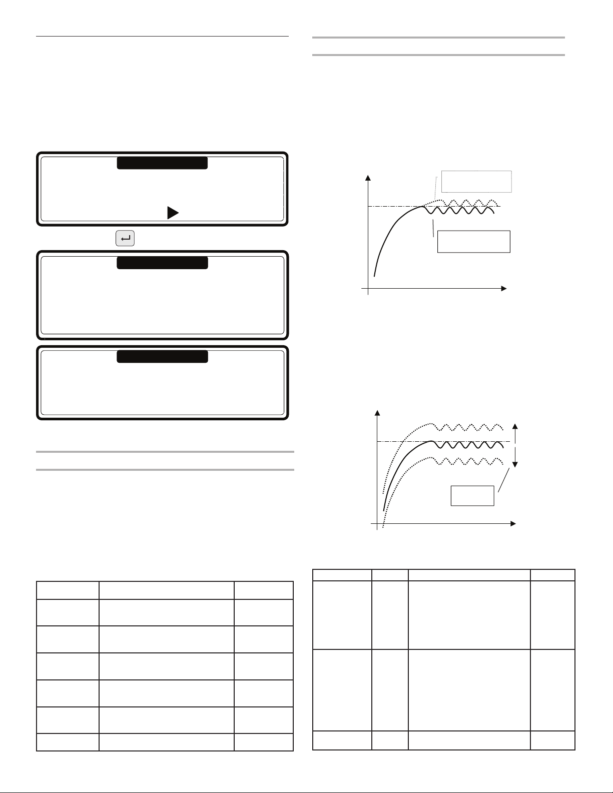
n Strict Temperature Control may be turned on or off.
When it is turned on, the target wash temperature is the
minimum temperature during the wash cycle. When this
function is off, accessory heat turns off when the water
reaches target temperature (see illustration below).
Water
Temperature
2 : Strict Temperat ure
Control
Target
4. Press ENTER.
Advanced Menu
1 DAQ Memory …
2 Hygienic Cycle …
3 Program Mode Lock …
4 Program Lock …
5 Traceability …
Advanced Menu
6Weighing …
7 Exit
5. The Advanced Menu contains 7 items on two screens.
Press 5 or 6 to select the desired menu item.
DAQ Memory Menu
The Data Acquisition (DAQ) memory stores information about
the use prole and functionality of the washer. This information
is usually applied in conjunction with Trace-Tech software.
n The DAQ memory collects information whenever the washer
is on. It does not collect information when the washer is off.
n The DAQ Storage Memory can be reset at the Conguration
Menu by the Reset Defaults function. All data stored in the
DAQ Memory will be lost.
DAQ Memory Menu Variables
Menu Item Description Limits
All Memory
Segments
Statistics
Segment
Traceability
Segment
Trace-Tech
Settings
Log
Segment
Exit Return to Advanced Menu.
Turns on all memory
segments.
Stores statistical information
about washer utilization.
Contains Traceability
information from the washer.
Stores setup information from
the Trace-Tech PC software
Contains the event log for
the washer.
On/Off
On/Off
On/Off
On/Off
On/Off
1 : Normal Temperature
Control
Strict Temperature Control
n Temperature Control Offset allows calibration with an
Time
external measurement device. The offset control is
adjustable between 23° and 41°F (-5° and +5° C)
(see illustration below).
NOTE: Calibration is only necessary to assure a minimum
temperature is attained during a hygienic cycle. It is not
required for normal washer use.
Temperature
Target
Offset
adjustment
Temperature Calibration Offset
+ 5
- 5
Time
Temperature Calibration Offset Variables
Menu Item Default Information Limits
Strict
Temperature
Control
No
The Strict Temperature
Control of the wash
computer ensures laundry is
No/Yes
washed at the programmed
target temperature.
Temperature
Calibration
Offset
0
By changing the
Temperature Calibration
Offset setting,
23/32/41°F
(-5/0/5°C)
the water temperature sensor
setting is equalized with the
external reference
temperature sensor.
Exit Return to Advanced Menu.
15
Page 16
Program Mode Lock Menu
The access to the Program Mode can be locked by a password.
It means that without password you can’t have access to the
Main Menu Screen.
Menu Item Description Default Limits
Password . . . Enter a 4 digit value for the Password and press
Edit Password …
New Password ….
No Password …
Old Password …
Exit Return to Advanced Menu
ENTER.
NOTE: The password will not be requested if it has
not been set.
Insert a 4 digit numeric value to create a new
password.
Select the menu item “No password” if you want to
get rid of the password.
To change the Password enter old password, create
a new password.
None 0000–99999
Program Lock Menu
Each wash program can be locked individually.
When the program is locked, it means no settings can be
changed anymore.
It avoids that programs once created get changed by somebody
else.
To get access to this menu a password is needed if it has been
set.
Menu Item Description Default Limits
Programs …
1 HOT WASH Unlocked
2 WARM WASH Locked
…
99 Program 99 Unlocked
EXIT
Each program can be locked - unlocked individually.
When the program is locked, it means Program
settings can no longer be changed.
This helps avoid created programs being changed
by another.
Unlocked
16
Page 17

Traceability Menu
The Traceability Menu allows information collection regarding
cycle parameters. This information can be used to verify that any
wash cycle meets given requirements. For further information
on the collection and management of this information see the
Traceability Management Manual W10243988.
Traceability Menu Options and Defaults
Menu Item Description Default Limits
Enable Traceability First you have to select Traceability to obtain the
Traceability Report
Stored Cycles …
Start Print Last Report
Disability Traceability Errors Err 81 and Err 82 can be switched off if they are
Exit Return to Advanced Menu.
other menu items.
A report can be created for each wash cycle.
A printer or PC can be connected to the washer by
Serial RS485 communication bus.
• “Store DAQ”: stores all wash process data in the
DAQ memory. When the PC is connected to the
washer, the data is sent and stored on the PC.
• “Store PC”: sends continuously all wash cycle data
to the PC, where it is stored.
• “Print Last” sends the report directly to a printer.
The command is given by “Start Print Last Report.”
• “Print All” sends the report in real time to a printer.
If Store DAQ is selected, the display shows the
number of wash cycles stored in DAQ memory.
If Print Last is selected, the menu item “Start Printing
the Last Stored Report” is displayed.
interfering with the wash cycle.
No No/Yes
Store DAQ
XX%
No
No No/Yes
Store DAQ
Store PC
Print Last
Print All
No/Yes
17
Page 18
Initialization Menu
Initialization Menu allows you to choose standard default
program settings for your application.
1. Make sure power is ON and no program is running.
2. Enter PROGRAM MODE. The Main Menu will be displayed.
3. Press 5 or 6 to select the Initialization Menu.
Main Menu
Initialization Menu …
Program Menu … Configuration Menu …
Service Menu … Advanced Menu …
4. Press ENTER.
Initialization Menu Selections and Defaults
Menu Item Description Default Range
Language Language selection for Program Mode: English,
Spanish, or French
Service Interval Number of cycles at which maintenance is required.
3000: Top Soap Dispenser washers
9999: Front/Side Soap Dispenser washers
Buzzer Time The time the Buzzer beeps at end of wash
cycle while “Unload” is displayed.
Allow Advance The Advance function allows the user to skip a
sequence or change sequence duration.
Automatic Cool Down Automatic cool down selection*. Yes No/Yes
Wait for Temp Wash Process time is put on hold until the
programmed temperature is reached.
English List
3000
9999
5 sec 0–99
Yes No/Yes
Yes No/Yes
1–9999
Manual Override Activates the Special Function keys on the touch
pad. The operator can directly operate the water inlet,
drain, heating, and spin speed functions.
NOTE: It is not possible to manually direct the washer
to perform an unsafe sequence of functions.
Example: If there is no water in the drum, the
HEATING special function keypad can’t be activated.
*Automatic Cool Down
n To avoid mechanical temperature shock and to extend the life time of your washer, after a hot wash, cold water is injected bit
by bit. As a result at the end of the hot wash, the temperature will be lowered to about 65°C (150°F).
n The automatic cool down function will only be functional if a hot wash with a temperature above 65°C (150°F) has been
programmed and if a cold water inlet valve is programmed in the next step. When a Cool down sequence has been
programmed, the automatic cool down will not function.
n The automatic cool down differs from a normal cool down sequence. The purpose of a normal cool down sequence is to
avoid the shrinking of the garments. (Takes more time).
Yes No/Yes
18
Page 19
Initialization Menu Selections and Defaults (continued)
Menu Item Description Default Range
Temperature Balance Temperature balance, controls water temperature
by regulating the cold and hot water valves. (Some
wash temperatures may require additional heat.)
Motor On Time Normal wash action, drum turns for 12 seconds.
Recommended 3 sec for Gentle wash action.
(= suggested values for the Program Menu)
Motor Off Time Drum is stopped for 3 seconds for normal action.
12 sec recommended for Gentle wash action.
Smart Motion This option decreases the drum RPM during water
lling; therefore, the laundry absorbs water more
quickly and washing efciency increases.
Hot Water Heater Temp. The water heater temperature should be the same
as the temperature of the hot water supply.
Temp. Overshoot Prot. This is the % below the target temperature heat is
switched off to avoid overshoot. Heating will begin
after 30 seconds if the target temperature is not
reached.
Max. Heating Time Generates an error message if the target water
temperature is not reached within the Maximum
Heating time (Err 14).
If 99 is entered, no error message will display.
The washer will continue heating until the target
water temperature is reached.
Max. Water Fill Time Generates an error message if the target water level
is not reached within the Max. Water Fill Time (Err 11).
If 99 is entered, no error message will display. The
washer will continue lling until the target water level
is reached.
Overll Detection An error message is generated if the water level
exceeds the programmed water level by more than
the programmed number of units (Err 12). If the
washer uses steam heating, the steam installation
should have adequate power to quickly heat the
water. Slow heating will raise the water level and
also cause increased energy and laundry product
consumption. Reduce the programmed water
temperature to the minimum level necessary to
achieve satisfactory results.
Yes No/Yes
12 sec 1–99 sec
3 sec 1–99 sec
Yes No/Yes
140°F
(60°C)
00 % 0–30 %
60 min 10–90 min
10 min 5–99 min
10 units 10–25 units
122–176°F
(50–80°C)
99
External Wait Control Liquid soap supply system:
Selection for a washer connected to a central liquid
soap supply system.
The central pump system is able to Pause the washer,
before continuing the wash process, until the central
pump system is free to pump the liquid soap supply
into the washer.
Heating, (for installations with limited power supply):
You can disable the heating system of the washer
with an external signal.
The heating will switch on again, and the wash
process will continue, as soon as the external signal
is switched off.
Main Water Pressure Front/Side Soap Dispenser washers only: The laundry
product containers may not fall during the water
intake sequence if the water pressure is too low. Set
to “Low” if the water pressure is weak or if the water
supply pressure decreases notably during delivery.
Exit Return to Main Menu
No No/Yes
High Low/High
19
Page 20
Edit Step
Menu
_
o
Select Step N
Add Step...
Edit Step...
Insert Step...
:
o
Select Step N
View Step . .
View Step...
Delete Step...
Step Menu Exit
Exit
4.
4.
4.
4.
No WashSpray
tu
tu
Flush
tu
Soak
tu
RPM _
RPM
C
o
Temp _
Drain Valve 1 tu
Supply A _”
Spray 1
Spray 2
On Time _ Sec
Off Time _ Sec
Time _ Min
Signal No
Inlet _
Level _
RPM _
Detergents Menu...
Time _ Min
Signal No
On Time _ Sec
Off Time _ Sec
Time _ Hour
Signal No
Drain
tu
Static Drain
5. 5.
tu
RPM
On Time _ Sec
Off Time _ Sec
Drain Valve 1 tu
Drain Valve 1 tu
Time _ Min
Time _ Min
Step Exit
Step Exit
Legend:
Select a new program Sub-menu and go to the next item: ENTER.
p Select the Menu item: Press UP or DOWN. qtu Select list: Press LEFT or RIGHT.
8
-- Insert a value or Select another List element.
or
Conrm a menu item and go to the next menu item: ENTER.
_
o
Program Menu
Select Program N
Name XXXX
View...
Edit...
New...
Copy...
Delete...
Wash Program Creation and Adjustment
2. 3.
Program Menu Exit
Program
Copy From
8
Final Rinse
Inlet _
Level _
RPM _
Detergents Menu...
On Time _ Sec
Off Time _ Sec
Time _ Min
4.
tu
Program Wash Part Step
Rinse
4.
tu
Cool Down
4.
tu
Wash
4.
tu
Inlet _
Level _
C
o
Temp _
RPM _
C
o
Temp _
Inlet _
RPM _
Drain Valve 1 tu
Level _
Detergents Menu...
On Time _ Sec
RPM _
Signal No
On Time _ Sec
Off Time _ Sec
Time _ Min
Signal No
Off Time _ Sec
Time _ Min
Signal No
Detergents Menu...
On Time _ Sec
Off Time _ Sec
Time _ Min
u
Signal No
No Drain
Step Exit
5.
tu
Program Drain Step
Spin
Drain Valve 1 tu
RPM _
Time _ Min
5.
tu
Drain
5.
Step Exit
Drain Valve 1 tu
Time _ Min
Step Exit
Keyswitch: Program
NOTE: Depending on the washer conguration and
initialization, some menu items will not be displayed.
20
Initialization Menu
Program Menu
Service Menu
1.
Diagnostic Menu
Conguration Menu
Pre Wash
4.
C
o
Temp _
Inlet _
Level _
RPM _
Detergents Menu...
On Time _ Sec
Off Time _ Sec
Time _ Min
Signal No
= Only for washers with Top Soap Dispenser
1. Select the Program Menu.
2. Enter the desired Program Number.
For a new program enter the program name.
Select Program View, Edit, Insert, New, Copy or Delete.
3. Select the appropriate Step Function: Add, Edit, Insert, View, or Delete.
Enter the desired Step Number.
4. Select the appropriate Wash Step Function.
Enter the appropriate Step Function settings.
5. Select the appropriate Drain Function.
Enter the appropriate Step Function settings.
Exit the Step Menu.
Page 21
CYCLE PROGRAMMING
Press the ENTER button to confirm your selection.
Go to
5.3. STEP : PROGRAM FUNCTIONS
Specic functions have been implemented in the Full Control
washer controller to allow for a detailed programming.
Functions for the Complete Program:
n Program Number: Select the wash program.
n Name: Insert or modify the name for the program.
n View: Inspect the program settings without making changes.
n Edit: Make changes to a program.
n New: Create a new program.
n Copy: Make a copy of an existing program.
n Delete: Erase a program.
n Exit: Leave the Program Menu.
Functions for the Program Steps:
n Step Number: Select the program step.
n Add: Add a program step at the end of the program.
n Edit: Adjust a program step.
n Insert: Add a program step between two other steps.
n View: Inspect the step settings without making changes.
n Delete: Delete a step.
n Exit: Leave the program step menu.
Follow the owchart on the proceeding page step-by-step.
Program Menu
Initialization allows you to choose standard default program
settings for your application.
1. Make sure power is ON and no program is running.
2. Enter PROGRAM MODE. The Main Menu will be displayed.
3. Press 5 or 6 to select the Program Menu.
Main Menu
Initialization Menu …
Program Menu … Configuration Menu …
Service Menu … Advanced Menu …
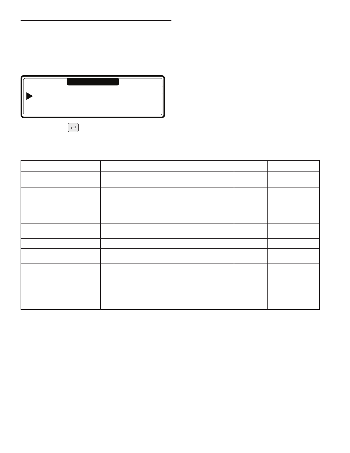
4. Press ENTER.
Program Functions
Program Menu
Select Program N°: 1
Name: HOT WASH
View … New … Delete …
Edit … Copy … Exit
Menu Item Description
Select Program N: Select program 1 to 99.
Name: _ _ _ _ _ _ _ _ _ The Program Name describes the
wash cycle. Press ENTER when the
cycle name is complete. Select the
Character with the 5 and 6 arrows.
Select the character position with
the 3 and 4 arrows.
View Allows you to see the Program
Settings without changing them.
Edit Allows you to change a program
by selecting new sequences from a
menu or by changing values in an
existing step. You can also add,
insert or delete sequences from
an existing program.
New To create a new program, you
have to make use of the add step
function. By adding steps the
program will grow step by step.
A conrmation is asked rst to
delete the old program.
Copy
HINT: To create a new program,
with minor changes from an existing
program, it is easier to copy an
existing program than to make
changes.
Insert the desired program number
Copy From
Program N°: XXX
from which you want to copy the
program.
The standard programs can be
selected at the program numbers
101–115.
Program number 101 corresponds
with program 1.
Program number 102 corresponds
with program 2.
Program number 115 corresponds
with program 15.
A conrmation is asked rst to
delete the old program.
Delete a Program To get rid of an existing program,
use the delete program function.
The complete program will be
erased at once.
A conrmation is asked rst to
delete the old program.
Exit Return to Main Menu
: Program Lock Symbol
In the Advanced Menu, it is possible to lock/unlock each wash
program individually. The wash program cannot be changed
when the Program Lock Symbol is displayed. Only the View
function will be operational, all others will be disabled until
unlocked.
21
Page 22
Program Step Function
5.4. STEP : PROGRAM STEP FUNCTION
Edit Step Menu
Program 1: Hot Wash
Select Step N°: 1
Add step … Insert Step … Delete Step …
Edit Step … View Step … Exit
Menu Item Description
Select Step N°: 1 Insert the desired step number.
Add Step To create new programs, a new extra step should be added at the end of the program.
Edit Step To change values and list elements from an existing step.
Insert Step A new step is inserted between two existing steps.
View Step Before making changes in a wash program, it is recommended to have a look at the actual
Delete Step An existing Step in the program disappears when it is deleted. A conrmation is asked
Exit Return to Program Menu
Step 1 to 99 can be selected.
If the number is not accepted, this means that the step is not available.
No Step number must be entered for “Add Step” function.
If the number is not accepted, this means there is no step with a step number that is equal to a
selected step number minus one. A new step can only be inserted between two available steps.
settings in the view function. No changes can be made in the View Step function.
before deleting the Old Step.
22
Page 23
Program the Wash Cycle
5.5. STEP : PROGRAMMING THE WASH PART
Program
Number
Prog 1
Original
Value
Wash
STEP
Wash
Spin part
Spin
Info
Action
Time: 8.0 Min
STEP 2
5
8.0 [4.0-20.0]
Step
Number
This section provides a detailed explanation about programming the Wash Sequences.
n Each program step contains a Wash segment and a Drain/Spin segment.
n First, the Wash segment must be selected; each item can be programmed.
n Next the Drain/Spin segment must be selected, each item can be programmed.
n Without making changes you can see item by item, by pressing ARROW DOWN or UP.
n If you want to make changes:
– Insert a new value.
– Enable or disable a setting by pressing YES or NO.
– Select a list element by pressing LEFT ARROW or RIGHT ARROW.
NOTE: You must press ENTER to conrm each selection.
n Default values were pre-programmed into each step to make programming easier.
See WASH PROGRAMS for a general explanation of creating wash programs.
n See each list element by using the LEFT ARROW or RIGHT ARROW symbols at the right side of the display.
n The arrow down symbol on the display points to the last Menu Item: EXIT.
Menu Value
Item
Menu Item
Limits
Menu Item
Position
Menu Item
23
Page 24
Selecting the wash cycle
If Add Step, Edit Step, or Insert Step, are selected,
choose the wash sequence now.
Depending on the machine type, with top or front soap
dispenser, you have more or less sequences available.
Selecting the wash cycle
If Add Step, Edit Step, or Insert Step, are selected, choose the
Prog XX
Step YY
Pre-Wash
Type: Pre-Wash
Extract
z
Wash Sequence now.
The number of available sequences depends on the Machine
Type and whether it is equipped with top or Front/Side Soap
Dispensers.
For Washers with Top Soap Dispenser:
Prewash Wash Cool Down Rinse Final Rinse Soak Flush Spray No Wash
For Washers with Front/Side Soap Dispenser:
Wash Cool Down Rinse Soak Flush Spray No Wash
For a new step, as a default, the rst displayed function is the Wash Sequence.
n Press LEFT ARROW or RIGHT ARROW to choose the desired sequence.
n Press ENTER to conrm.
n Use ARROW DOWN if you accept the pre-programmed default value.
24
Page 25
The Prewash Sequence
Prewash Wash Cool Down Rinse Final Rinse Soak Flush Spray No Wash
Only for washers with Top Soap Dispensers.
Menu Item Description Default Limits
Temperature The water temperature. 104°F
(40°C)
Inlet The suggested Inlet Valves are related to the temperature and
Level The suggested water level depends on the Machine Type. Normal
RPM The suggested RPM depends on the Machine Type. – See Table A-6
Detergents Menu...
Supply 1, ..., 8
On Time The wash action, motor On Time.
Off Time The wash action, motor Off Time.
Time The Prewash Sequence Time.
the Soap Box to be used.
If you insert other Inlet Valves than suggested, problems
can occur at the water ll process.
Time selection for external liquid soap supplies. You can
program up to 4 supplies at the same time, attempting
to program more than 4 supplies will generate an error
message. Only 4 non-zero supplies per step are accepted.
(Liquid soap supplies must be switched on at the Conguration
Menu.)
Gentle wash action: 3 seconds
(The suggested default values can be adjusted in the
Initialization Menu)
Gentle wash action: 12 seconds
(The suggested default values can be adjusted in the
Initialization Menu)
(for 0 minutes the Prewash sequence will be skipped
(programmable in steps of 0.5 minutes)
2–3 1–6
Low
0 sec 0–99 sec
12 sec 1–99 sec
3 sec 1–99 sec
4 min 0–99.5 min
33.8–113°F
(1–45°C)
See Table A-4
Signal When a signal is programmed, a pause will be introduced at
the end of the Wash Step. This allows the operator to add
soap for the next step. A buzzer signal warns the operator
that the cycle has been interrupted.
No No/Yes
25
Page 26
The Wash Sequence
Prewash Wash Cool Down Rinse Final Rinse Soak Flush Spray No Wash
Menu Item Description Default Limits
Temperature The water temperature. 140°F
(60°C)
Inlet (Top Soap
Dispenser)
(Front/Side Soap
Dispenser)
Level The suggested water level depends on the Machine Type. Normal
RPM The suggested RPM depends on the Machine Type. – See Table A-6
Detergents Menu. . .
Box A, B, C, D, E
Supply 1, ..., 8
On Time The wash action, motor On Time.
Off Time The wash action, motor Off Time.
Time The Wash Sequence Time.
Signal When a signal is programmed, a pause will be introduced
The suggested Inlet Valves are related to the temperature
and the Soap Box to be used.
NOTE: If you insert other Inlet Valves than the suggested
ones, problems can occur at the water ll process.
Time selection for Soap Boxes (hopper) and external liquid
soap supplies. You can program up to 4 supplies at the
same time, attempting to program more then 4 supplies
will generate an error message.
Reset the time of the supplies back to 0. Only 4 non-zero
times values can be programmed.
- Liquid soap supplies must be switched on in the
Conguration Menu.
- Box A, B, C, D, and E are only available on Front/Side Soap
Dispenser washers.
Gentle wash action: 3 seconds
(The suggested default values can be adjusted in the
Initialization Menu)
Gentle wash action: 12 seconds
(The suggested default values can be adjusted in the
Initialization Menu)
(for 0 minutes the Wash Sequence will be skipped)
(programmable in steps of 0.5 minutes)
at the end of the Wash Step. This allows the operator to add
soap for the next step. A buzzer signal warns the operator
that the cycle has been interrupted.
3, 4, 5
2, 3
Low
0 sec
0 sec
12 sec 1–99 sec
3 sec 1–99 sec
7 min 0–99.5 min
No No/Yes
33.8–197.6°F
(1–92°C)
1–6
1–3
See Table A-4
0–9 sec
26
Page 27
The Cool Down Sequence
Prewash Wash Cool Down Rinse Final Rinse Soak Flush Spray No Wash
n After a hot wash you can program a Cool Down Sequence to avoid temperature shock and shrinking
of the garments.
n The drain step after the hot wash must be put on NO DRAIN.
n No inlets are programmable:
– For Top Soap Dispenser washers: inlet 6 is the standard inlet.
– For Front/Side Soap Dispenser washers: inlet 2 is the standard inlet.
n The water level cannot be programmed as the process of adding and draining water does not allow this.
IMPORTANT: Do not program a drain sequence before a cool down sequence.
Menu Item Description Default Limits
Temperature The water temperature 140°F
(60°C)
RPM The suggested RPM depends on the Machine Type. –
Drain Valve Only available on washers with both a normal Open and
normal Closed Drain valve.
On Time The wash action, motor On Time.
Gentle wash action: 3 sec.
(The suggested default values can be adjusted in the
Initialization Menu)
Off Time The wash action, motor Off Time.
Gentle wash action: 12 sec.
(The suggested default values can be adjusted in the
Initialization Menu)
Time The programmed time = time needed to decrease the
water temperature.
Once the programmed temperature has been reached,
the next Sequence will be started.
(for 0 minutes the Cool Down sequence will be skipped)
(programmable in steps of 0.5 minutes)
IMPORTANT: If a short time is programmed, the water
temperature will decrease fast.
Recommendation: Program 1 minute for each 37.4°F (3°C)
temperature drop.
Example: For a hot wash of 194°F (90°C) and a Cool Down
Sequence of 140°F (60°C) a time of about 86°F (30°C)/37.4°F
(3°C) = 10 minutes should be programmed for the Cool Down
Sequence.
1 1–2
12 sec 1–99 sec
3 sec 1–99 sec
7 min 0–99.5 sec
33.8–140°F
(1–60°C)
Signal When a signal is programmed, a pause will be introduced at
the end of the Wash Step. This allows the operator to add
soap for the next step. A buzzer signal warns the operator
that the cycle has been interrupted.
No No/Yes
27
Page 28
The Rinse Sequence
Prewash Wash Cool Down Rinse Final Rinse Soak Flush Spray No Wash
n No temperature can be programmed because a Rinse is only possible with cold water.
Menu Item Description Default Limits
Inlet (Top Soap
Dispenser)
(Front/Side Soap
Dispenser)
Level The suggested water level depends on the Machine Type. Normal
RPM The suggested RPM depends on the Machine Type. – See Table A-6
Detergents Menu…
Box A, B, C, D, E
Supply 1, …, 8
On Time The wash action, motor On Time.
3 Inlets can be programmed.
The suggested Inlet Valves are related to the
temperature and the Soap Box to be used.
IMPORTANT: If you insert other Inlet Valves than the
suggested ones, problems can occur at the water ll
process.
Time selection for Soap Boxes (hopper) and external liquid
soap supplies.
You can program up to 4 supplies at the same time. If you
have programmed more then 4 supplies an error message
will be generated.
Reset the time of the supplies back to 0. Only 4 non-zero
times values can be programmed.
– Liquid soap supplies must be switched on in the
Conguration Menu.
– Box A, B, C, D, and E are only available on Front/Side
Soap Dispenser washers.
Gentle wash action: 3 sec.
(The suggested default values can be adjusted in the
Initialization Menu)
2, 5, 6
2
High
0 sec
0 sec
12 sec 1–99 sec
1, 2, 5, 6
1, 2
See Table A-4
0–99 sec
Off Time The wash action, motor Off Time.
Gentle wash action: 12 sec.
(The suggested default values can be adjusted in the
Initialization Menu)
Time The Rinse Sequence Time.
(for 0 minutes the Rinse sequence will be skipped)
(programmable in steps of 0.5 minutes)
Signal When a signal is programmed, a pause will be introduced at
the end of the Wash Step. This allows the operator to add
soap for the next step. A buzzer signal warns the operator
that the cycle has been interrupted.
3 sec 0–99 sec
2 min 0–99.5 min
No No/Yes
28
Page 29

The Final Rinse Sequence
Prewash Wash Cool Down Rinse Final Rinse Soak Flush Spray No Wash
n Only for top dispenser washers.
n No temperature can be programmed because a Final Rinse is only possible with cold water.
Menu Item Description Default Limits
Inlet (Top Soap
Dispenser)
Level The suggested water level depends on the Machine Type. Normal
RPM The suggested RPM depends on the Machine Type. – See Table A-6
Detergents Menu…
Supply 1, …, 8
On Time The wash action, motor On Time.
Off Time The wash action, motor Off Time.
3 Inlets can be programmed.
The suggested Inlet Valves are related to the temperature
and the Soap Box to be used.
IMPORTANT: If you insert other Inlet Valves than the
suggested ones, problems can occur at the water ll
process.
Time selection for external liquid soap supplies.
You can program up to 4 supplies at the same time. If you
have programmed more then 4 supplies an error message
will be generated.
Reset the time of the supplies back to 0. Only 4 non-zero
times values can be programmed.
– Liquid soap supplies must be switched on in the
Conguration Menu.
Gentle wash action: 3 sec.
(The suggested default values can be adjusted in the
Initialization Menu)
Gentle wash action: 12 sec.
(The suggested default values can be adjusted in the
Initialization Menu)
1
1, 6
High
0 sec
0 sec
12 sec 1–99 sec
3 sec 0–99 sec
1, 2, 5, 6
See Table A-4
0–99 sec
Time The Final Rinse Sequence Time.
(for 0 minutes the Final Rinse sequence will be skipped)
(programmable in steps of 0.5 minutes)
Signal When a signal is programmed, a pause will be introduced at
the end of the Wash Step. This allows the operator to add
soap for the next step. A buzzer signal warns the operator
that the cycle has been interrupted.
2 min 0–99.5 min
No No/Yes
29
Page 30

The Soak Sequence
Prewash Wash Cool Down Rinse Final Rinse Soak Flush Spray No Wash
Menu Item Description Default Limits
Temperature The water temperature 104°F
Inlet
(Top Soap Dispenser)
(Front/Side Soap
Dispenser)
Level The suggested water level depends on the Machine Type. Normal
RPM The suggested RPM depends on the Machine Type. – See Table A-6
Detergents Menu…
Box A, B, C, D, E
Supply 1, …, 8
On Time The wash action, motor On Time.
Off Time The wash action, motor Off Time.
Time The Soak Sequence Time.
Signal When a signal is programmed, a pause will be introduced at
The suggested Inlet Valves are related to the
temperature and the Soap Box to be used.
IMPORTANT: If you insert other Inlet Valves than the
suggested ones, problems can occur at the water ll
process.
Time selection for Soap Boxes (hopper) and external
liquid soap supplies.
You can program up to 4 supplies at the same time.
If you have programmed more then 4 supplies an error
message will be generated.
Reset the time of the supplies back to 0. Only 4 non-zero
times values can be programmed.
– Liquid soap supplies must be switched on in the
Conguration Menu.
– Box A, B, C, D, and E are only available on Front/Side
Soap Dispenser washers.
(The suggested default values can be adjusted at the
Initialization Menu)
(The suggested default values can be adjusted at the
Initialization Menu)
(for 0 minutes the Soak Sequence will be skipped)
(programmable in steps of 0.5 minutes)
the end of the Wash Step. This allows the operator to add
soap for the next step. A buzzer signal warns the operator
that the cycle has been interrupted.
(40°C)
2, 3
2, 3
Low
0 sec
0 sec
12 sec 1–99 sec
10 min 1–99 min
1 hour 0–25.5 hour
No No/Yes
33.8–113°F
(1–45°C)
1–6
1, 2, 3
See Table A-4
0–99 sec
30
Page 31

The Flush Sequence
Prewash Wash Cool Down Rinse Final Rinse Soak Flush Spray No Wash
Only for Top Soap Dispenser washers.
n No water level can be programmed as the water will raise and escape by the overow hole.
n No water inlets can be programmed as only cold water from water inlet 6 is used.
n No supplies can be programmed.
Menu Item Description Default Limits
RPM The suggested RPM depends on the Machine Type. – See Table A-6
On Time The wash action, motor On Time.
Gentle wash action: 3 sec.
(The suggested default values can be adjusted in the
Initialization Menu)
Off Time The wash action, motor Off Time.
Gentle wash action: 12 sec.
(The suggested default values can be adjusted in the
Initialization Menu)
Time The Flush Sequence Time.
(for 0 minutes the Flush sequence will be skipped)
(programmable in steps of 0.5 minutes)
Signal When a signal is programmed, a pause will be introduced at
the end of the Wash Step. This allows the operator to add
soap for the next step. A buzzer signal warns the operator
that the cycle has been interrupted.
12 sec 1–99 sec
3 sec 1–99 min
10 min 0–99.5 min
No No/Yes
31
Page 32

The Spray Sequence
Prewash Wash Cool Down Rinse Final Rinse Soak Flush Spray No Wash
n Water or Liquid is injected at Distribution or Low Spin Speed
n No standard water inlets can be programmed in this function.
n The liquid will be injected based on soap supply programming.
Menu Item Description Default Limits
RPM The suggested RPM depends on the Machine Type. – See Table A-6
Drain Valve Only available on washers with both:
Detergents Menu…
Box A, B, C, D, E
Supply 1, …, 8
Signal When a signal is programmed, a pause will be introduced at
a normal Open and normal Closed Drain valve.
Time selection for Soap Boxes (hopper) and external
liquid soap supplies.
You can program up to 4 supplies at the same time.
If you have programmed more then 4 supplies an error
message will be generated.
Reset the time of the supplies back to 0. Only 4 non-zero
times values can be programmed.
– Liquid soap supplies must be switched on in the
Conguration Menu.
– Box A, B, C, D, and E are only available on Front/Side
Soap Dispenser washers.
the end of the Wash Step. This allows the operator to add
soap for the next step. A buzzer signal warns the operator
that the cycle has been interrupted.
No Wash Sequence
Prewash Wash Cool Down Rinse Final Rinse Soak Flush Spray No Wash
1 1–2
0–99 sec
0 sec
0 sec
No No/Yes
In case of a No Wash Sequence, the wash function of the programmed step is skipped.
32
Page 33

Program the Drain Step
A Drain/Extraction step is required after each wash step.
NOTE: You do not need to program a drain sequence before an
extraction sequence because the water will automatically drain
during the extraction sequence.
SELECTING THE DRAIN/EXTRACTION STEP
The number of drain functions and options depends on
the Machine Type.
n For a new step, the rst sequence that is displayed is the
Drain sequence (default).
n Select the desired Drain step sequence from the list by
pressing LEFT ARROW or RIGHT ARROW.
n Press ENTER to conrm your selection.
n You can also use ARROW DOWN if you
accept the pre-programmed default value.
Prog XX
Step YY
Wash
Type: Drain
Drain
z
Drain Sequence
Drain Extract No Drain Static Drain Reversing Drain
Menu Item Description Default Limits
Drain Valve Only available on washers with both a normal Open and
normal Closed Drain valve.
Time The Drain Sequence Time.
(for 0 minutes the Drain sequence will be skipped)
(programmable in steps of 0.5 minutes)
Exit Return to Edit Program Menu.
1 1–2
0.5 min 0–9.5 min
33
Page 34

The Extract Sequence
Drain Extract No Drain Static Drain Reversing Drain
Menu Item Description Default Limits
Drain Valve Only available on washers with both a normal Open and
normal Closed Drain valve.
RPM The suggested RPM depends on the Machine Type. See Table A-6
Time The Extract Sequence Time.
(for 0 minutes the Extract sequence will be skipped)
(programmable in steps of 0.5 minutes)
Exit Return to Edit Program Menu.
1 1–2
4.5 min 0–9.5 min
The No Drain Sequence
Drain Extract No Drain Static Drain Reversing Drain
• The Drain/Extraction part of the programmed step is skipped.
IMPORTANT: For some specic functions “No Drain” must be programmed.
Example: If you want to program a Cool Down Sequence, then “No Drain” must be programmed between the Hot Wash and the
Cool Down Sequence.
Menu Item Description Default Limits
Exit Return to Edit Program Menu.
Static Drain Sequence
Drain Extract No Drain Static Drain Reversing Drain
The drum is at standstill while the water is drained.
Menu Item Description Default Limits
Drain Valve Only available on washers with both a normal Open and
normal Closed Drain valve.
RPM The suggested RPM depends on the Machine Type. See Table A-6
Time The Static Drain Sequence Time.
(for 0 minutes the Static Drain Sequence will be skipped)
(programmable in steps of 0.5 minutes)
Exit Return to Edit Program Menu.
IMPORTANT: In a Static Drain Sequence, the garments are not distributed around the drum while the water is drained. When the
Spin Sequence starts, the garments are very imbalanced and the imbalance (tilt) function will be activated. To avoid imbalance,
(tilt) activation, do not program a Spin Sequence immediately after a Static Drain Sequence.
1 1–2
4.5 min 0–9.5 min
34
Page 35

The Reversing Drain Sequence
Drain Extract No Drain Static Drain Reversing Drain
The drum is reversing while the water is drained.
Menu Item Description Default Limits
Drain Valve Only available on washers with both a normal Open and
normal Closed Drain valve.
RPM The suggested RPM depends on the Machine Type. – See Table A-6
On Time The mechanical action, motor On Time.
(The suggested default values can be adjusted in the
Initialization Menu)
Off Time The mechanical action, motor Off Time.
(The suggested default values can be adjusted in the
Initialization Menu)
Time The Reversing Drain Sequence Time.
(for 0 minutes the Reversing Drain sequence will be skipped)
(programmable in steps of 0.5 minutes)
Exit Return to Edit Program Menu.
1 1–2
12 sec 1–99 sec
3 sec 1–99 min
0.5 min 0–9.5 min
35
Page 36

OPERATION
Start a Laundry Load
n The washer must be properly installed before operation.
See the Installation Instructions for your washer.
n Conguration and Initialization Menu must have the correct
settings before operation.
n Wash cycles will not start unless the washer control is in the
run mode.
1. Switch on the Power: The display will light up. When the
program is ready to be started, “Select Process _ _” will
display.
2. To load the washer: Open the door and load the laundry
into the drum. When the drum is loaded, close the door.
3. Put laundry products into the laundry product dispensers.
Put the correct amount of laundry products into the
dispensers.
Front/Side Soap Dispenser washers: At the Wash
Sequence, it depends of the pre-programmed
E
D
C
B
A
4. Start a wash program: Up to 99 programs can be selected.
The rst 15 are the standard Wash programs discussed in
“Programmed Cycles”. Additional programs are available
for North America. Insert the program number and press
START.
NOTE: If there is no program available for a specic
program
number, INVALID is displayed.
5. During the cycle, the cycle time will decrease minute by
minute and gives you an indication how long it will take
before the cycle is nished.
n For each Wash program Step, rst you will see the
n A Progress Bar shows the progression of the wash cycle.
soap supply signals in which boxes A, B, C, D,
or E you have to add laundry products.
Top Soap Dispenser washers: At the Wash
Sequence, it depends of the pre-programmed
water inlets in which compartment A, B, or C
you have to laundry products.
Wash Sequence, then you will see the Drain/Extraction
Sequence.
Program
Number
CHLORINE BLEACH
12
Step 2
Rinse
Wash Cycle
Name
Time Units
Minutes
35
Cycle Options
Time Delay
Entering a delay time is performed during washer startup as
follows:
1. Enter the selected Program Number.
2. Press DOT. The Delay time message will be
displayed. The door and the soap door must be closed rst.
3. Now you can insert the value for a delay time. “Washer will
start after _ _ : _ _” First insert a value for the Hours, then
insert a value for the minutes. The minimum delay time is
1 minute [ 00:01]. The maximum delay time is 99 hours
59 minutes [99:59].
4. Press START. The delay time will start to decrease and the
door will lock immediately. Once the delay time is over, the
wash cycle will start automatically.
NOTES:
n The Delay Time Sequence can be interrupted by
pressing Stop.
n “Select Cycle _ _” is displayed. Insert the program number
and press START.
Economic
If you accept the selection ECONOMIC at the Start of a new
cycle by pressing YES, the programmed water level will be
lowered by 20% (in units). If you do not want an ECONOMIC
level, press NO.
NOTES:
n Economic water levels should only be used for lightly soiled
and/or smaller volumes of garments. In other cases these
reduced water levels will give poor washing results.
n In the Initialization Menu you can enable/disable the
request for Economic at start up.
Advancing the Wash Program
n Press to increase Wash Sequence time.
n Press to decrease Wash Sequence time.
n Press START to skip this step.
Wash Time
When the wash program begins, REMAINING CYCLE TIME
displays and the time dot will blink. The REMAINING CYCLE
TIME counter will stop and the time dot will stop blinking if extra
time is required. The REMAINING CYCLE TIME counter will stop
when the washer requires extra time to:
n Fill the tub,
n Heat the water (if the Wait For Temperature option is
selected), or
n Drain the tub (if the water is not drained in 30 seconds
and the automatic extended drain time is started).
36
Wash/Spin
Sequence
Wash
Cycle Step
Progression
Bar
Remaining Time
Wash Cycle
Door
State
Page 37

Program End and Unloading
Program End
The time on the display counts down until 0. Once the
program cycle is nished, END PROGRAM is displayed.
The door lock will be released. You can open the door when
UNLOAD appears on the display. Open the door and unload
the washer. The message UNLOAD will be erased and the
washer is ready to start a new program. “Select Cycle _ _” is
displayed.
Messages During the Wash Cycle
Water Fill Process
When the water ll process is running, a picture of a tap is
shown on the display.
n Depending on the water temperature the cold and hot inlet
valves will be opened.
n The water level is measured by an electronic water
level sensor.
n If the Temperature Balance function is enabled, the Full
Control washer controller will control the water temperature
until the target temperature is reached. For Hot wash
programs, extra heating will be required after the ll
process to reach the programmed hot water temperature.
n In the standard wash tables you will nd a Normal Low and
Normal High water level.
n These are the standard water levels:
– The Normal Low water level is used for the Prewash,
Wash, and Soak Sequence.
– The Normal High water level is used for the Rinse and
Final Rinse Sequence.
n The water level can only be programmed between two
limits:
– The lower limit is above the heating elements and the
temperature sensor.
– The upper limit is below the overow hole.
Heating Process
When the water heating process is running, a picture of a
boiler is shown on the display.
n When “No Wait for Temperature” is selected: The washer
will heat until the time of the specic wash step is over or
if the programmed temperature was reached. Even if the
programmed temperature is not reached, the program will
start the next sequence if the time of the sequence is over.
n When “Wait for Temperature” is selected: The washer
will heat until the programmed temperature is reached.
The programmed time of the Wash Sequence will only
start counting down from the moment that the target
temperature was reached.
NOTE: If the washer does not have an accessory heating
system, do not select “Wait for Temperature” in the
Initialization Menu.
Cool Down Function
n Automatic cool down: This function avoids thermal shock
in the washer. For Hot washes above 149°F (65°C), cold
water is added at the end of the step.
n Programmed cool down: This function is recommended
to avoid the shrinking of the garments. Water is drained
and cold water is added bit by bit. The temperature of the
water in the tub will decrease slowly as a function of the
programmed Cool Down Sequence (temperature and time).
Flush Function
Only for washers with a Top Soap Dispenser:
n At the ll segment of the Flush Sequence, no water level is
programmed and the water will escape by the overow
hole.
n Larger soil particles will be separated from the garments
due to the water that is draining through the overow hole.
Spray Function
The special product is injected while the drain valve is open
and depending the programmed speed, the drum will spin at
distribution or low spin speed.
Unbalanced
When the washer load is off balance, the tilt switch may
activate during the Spin Sequence.
n The Spin Sequence will be interrupted and the garments in
the drum will be redistributed.
n The washer will try up to 10 times to redistribute the
garments.
NOTE: This function is only for MFS models.
Pause
When a signal has been programmed for the end of a Wash
Sequence the washer will stop the Program and the message
“Pause, Press Start to Continue” will be displayed.
n The buzzer will give a signal for the operator. Now the
operator can add laundry products.
n By opening the soap door, the buzzer is switched off (only
for Front/Side Soap Dispenser washers).
n By pressing START the program will continue to the next
program step.
Stop
By pressing STOP the program is interrupted. The washer will
rst go to a safe state. Then the message CONTINUE ?
is displayed.
n STOP: The program is stopped. A tumble sequence will be
completed before the door can be opened.
n START: The program restarts the last active step, and
continues with the rest of the program.
37
Page 38

Open Soap Box
(Only for washers with Front/Side Soap Dispensers)
By opening the soap dispenser door, the program is
interrupted immediately. First the washer will go over to a
safe state, then “Close Soap Door” displays. Once the soap
dispenser door is closed again, “CONTINUE ?” will display.
n STOP: The program is stopped. A tumble sequence will be
completed before the door can be opened.
n START: The program restarts the last active step, and
continues with the rest of the program.
NOTE: It is recommended to program a pause (signal) if you
want to ll the same Soap Box twice while the program is
running.
Wait State
It can occur that the normal washer operation has been
interrupted and that you have to wait until the full control
washer controller allows you to go on. You can recognize the
wait state by “Wait” appearing on the display and a decreasing
counter. This will occur when the power has been switched off
and on during a running wash cycle.
There is an automatic delay time before the washer can be
restarted because the software does not know how fast the
motor was spinning.
Failure Messages
When a failure has been detected by the full control wash
computer, a Failure Message is generated, to inform the
operator about the problem. Each error message contains:
n XX: The Program number
n YY: The Step number
n Err ZZZ: The error number
n Fault Message: The name of the error message
Out Of Order (Pr: XX St: YY)
Ask For Service
(Err ZZZ : Fault Message)
At the upper line, the program number and step number of the
interrupted program are displayed. The message “Unload !”
will inform you when you can open the door.
Safety conditions
If there is still water in the drum or if the temperature is too
high, it is not possible to open the door. The messages “Water
in cage” or “Too Hot” will be displayed together with the level
and the temperature.
NOTE: It is up to the operator to take the necessary
precautions if the drain valve is not functional and there is
still hot water in the tub at the end of the wash cycle. On the
display, the actual water temperature and level will display.
Wait until the water drains and the water cools before all
interventions because hot water can cause burns.
n If something goes wrong with the door lock, the program
will end immediately. For safety purposes, the door will stay
locked.
See “Troubleshooting” for more information on error handling.
Power interruptions
When a power interruption occurs while the washer is in
standby mode and no program cycle was started, the washer
will stay in standby mode. When a power interruption occurs
while the washer is washing or spinning, after the power
interruption, the message “Continue ?” will display.
n STOP: The program is stopped. A tumble sequence will be
completed before the door can be opened.
n START: The program restarts the last active step, and
continues with the rest of the program.
Special Function Keypads
The Special Function keypads “Info” and “Service” are
dedicated to supply the operator with more information
about the wash programs and the wash washer functions.
n Press INFO if you want to nd out what a program looks
like.
n If no program is running, you will get an overview of all
available programs.
n At each step are shown all the menu items.
n You can exit the Info Menu by pressing INFO again.
Service-State
n Press SERVICE-STATE if you want to inspect the actual
water temperature and level.
n At the Service-State Menu, you can review:
– The water temperature and water level
– The number of cycles that have been accumulated
(service due)
– The actual washer states at the running wash cycle
n By entering the Program Mode, the Service-State Menu will
not disappear after 1 minute.
n By pressing ARROW DOWN you will see all the menu
items.
n You can leave the Service-State Menu by pressing
SERVICE-STATE again.
Inlets 1, 2, 3 (4, 5, 6 )
n Press INLET 1, 2, 3 (4 , 5, 6) if you want to open a water
Inlet valve during a running process.
– Only functional at a running wash sequence.
– The corresponding inlet valve will be opened while you
are pressing the keypad.
NOTE: It may not be possible to activate the inlets
because of the washer safety overrides.
Drain
n Press DRAIN if you want to open the drain valve during a
running process.
– Only functional during a running wash sequence.
– The drain valve will be opened for the time you are
pressing the keypad.
Heating
n Press HEATING if you want to turn on heating
during a running sequence.
– Only functional during a running wash sequence.
– Heating will be switched on while you are depressing
the keypad.
NOTE: It may not always be possible to activate the
heaters because of the washer safety overrides.
38
Page 39

Speed Adjust
n Press SPEED ADJUST if you want to change the drum speed
during a running sequence.
– You can adjust the drum speed by inserting a new value.
– The drum speed options will depend on the Machine Type.
NOTE: It may not always be possible to change the spin
speed because of the washer safety overrides.
Water Recycling
n If the washer is connected with a water recycling system, a
signal from the water recycling tank can be connected to the
Full Control washer computer.
n If the tank is empty, then the diagnostic message “Err 40 no
ll recycle” will be shown on the display of the Full Control
washer controller.
PROGRAMMED CYCLES
The Full Control washer controller contains 15 pre-programmed
Standard Wash Programs. (Standard Programs: 1 to 15).
Programs 16 to 52 are special programs for North America.
NOTE: The programmed cycles are given as an example only.
Contact your soap supplier for assistance creating custom
programs.
Legend
Liquid Supply Times
The default liquid laundry product supply time is 30 seconds.
Water Inlet Valves
Washers with Top Laundry Product Dispensers
n Inlet Valve 1: Cold Hard Water (*) Soap Dispenser
Compartment “C” Final Rinse
n Inlet Valve 2: Cold Soft Water Soap Dispenser Compartment
“A” Pre wash
n Inlet Valve 3: Hot Soft Water Direct Inlet (Liquid)
n Inlet Valve 4: Hot Soft Water Soap Dispenser Compartment
“B” Main Wash
n Inlet Valve 5: Cold Soft Water Soap Dispenser Compartment
“B” Main Wash
n Inlet Valve 6: Cold Soft Water Direct Liquid Inlet
(*) If no cold hard water is available, then Inlet Valve 1 will function with
cold soft Water.
Washers with Front/Side Soap Dispenser
n Inlet Valve 1: Cold Hard Water (Inlet Valve 1 is not
operational, if no hard water is available)
n Inlet Valve 2: Cold Soft Water
n Inlet Valve 3: Hot Soft Water
n For the washers with Front/Side Soap Dispenser,
automatically the Inlet Valve for the water recycling
tank will be switched off and the Cold water inlet valve
will be switched on.
External Liquid Soap Boxes
n If the washer is connected with external soap pumps,
a signal from the soap supply reservoir can be connected
to the Full Control washer computer.
n If the Soap Box is almost empty, then the diagnostic
message “Err 39 out of soap” will be shown on the display
of the Full Control washer controller.
n So the operator does not have to check the soap supply
reservoirs continuously to avoid washing without soap.
Wash Action
Normal Wash Action
n A = 12 Seconds Action
n R = 3 Seconds Rest
Medium Wash Action
n A = 10 Seconds Action
n R = 5 Seconds Rest
Gentle Wash Action
n A = 3 Seconds Action
n R = 12 Seconds Rest
End-of-Cycle (EOC) Tumble
n A = 5 Seconds Action
n R = 5 Seconds Rest
RPM (Revolutions Per Minute)
n W: Type MFR (R)/MFS (F) = Washing Speed (32 – 50 RPM)
n D: Type MFR (R)/MFS (F) = Distribution Speed
(not changeable) (100 RPM)
n L: Type MFR (R)/MFS (F) = Low Extraction Speed, Standard
(500 RPM)
n H: Type MFS (F) = High extraction speed (625–1000 RPM)
(depending on the size of the washer)
Water Level
NL: Normal Low level
NH: Normal High level
EL = NL minus 3 units
EH = NH minus 3 units
39
Page 40

Wash program 1: Hot wash – 194°F (90°C)
Sequence Inlet Temp. Level Time R.P.M.* Soap Supply
WASH PROGRAMS
Step 1
Step 2
Step 3
Step 4
Step 5
Top Soap
Dispenser
Prewash/wash 2-3 2-3 86°F
Spin – – – 1 min L – –
Main wash 5-4-3 2-3 194°F
Drain – – – 30 sec D –
Rinse 1 2-5-6 2 – NH 2 min W (normal) – –
Spin – – – 1 min L – –
Rinse 2 2-5-6 2 – NH 2 min W (normal) – –
Spin – – – 1 min L – –
Rinse 3 1 (+6) 1 (2) – NL 3 min W (normal) C D = 30"
Final spin/Spin – – – 5.5 min H – –
Slowdown – – – x – – –
Tumble – – – 30 sec W (EOC) – –
* see legend at the beginning of this section
Front/Side
Soap
Dispenser
(30°C)
(90°C)
Top Soap
Dispenser
NL 5 min W (normal) A A = 30"
NL 10 min W (normal) B B = 30"
Front/Side
Dispenser
Soap
Wash program 2: Warm wash – 140°F (60°C)
Sequence Inlet Temp. Level Time R.P.M.* Soap Supply
Step 1
Step 2
Step 3
Step 4
Step 5
Top Soap
Dispenser
Prewash/wash 2-3 2-3 86°F
Spin – – – 1 min L – –
Main wash 5-4-3 2-3 140°F
Drain – – – 30 sec D –
Rinse 1 2-5-6 2 – NH 2 min W (normal) – –
Spin – – – 1 min L – –
Rinse 2 2-5-6 2 – NH 2 min W (normal) – –
Spin – – – 1 min L – –
Rinse 3 1 (+6) 1 (2) – NL 3 min W (normal) C D = 30"
Final spin/Spin – – – 5.5 min H – –
Front/Side
Dispenser
Soap
(30°C)
(60°C)
Top Soap
Dispenser
NL 5 min W (normal) A A = 30"
NL 10 min W (normal) B B = 30"
Front/Side
Soap
Dispenser
40
Slowdown – – – x – – –
Tumble – – – 30 sec W (EOC) – –
* see legend at the beginning of this section
Page 41

Wash program 3: Colored wash – 104°F (40°C)
Sequence Inlet Temp. Level Time R.P.M.* Soap Supply
Step 1
Step 2
Step 3
Step 4
Step 5
Top Soap
Dispenser
Prewash/wash 2-3 2-3 86°F
Spin – – – 1 min L – –
Main wash 5-4-3 2-3 104°F
Drain – – – 30 sec D –
Rinse 1 2-5-6 2 – NH 2 min W (normal) – –
Spin – – – 1 min L – –
Rinse 2 2-5-6 2 – NH 2 min W (normal) – –
Spin – – – 1 min L – –
Rinse 3 1 (+6) 1 (2) – NL 3 min W (normal) C D = 30"
Final spin/Spin – – – 5.5 min H – –
Slowdown – – – x – – –
Tumble – – – 30 sec W (EOC) – –
* see legend at the beginning of this section
Front/Side
Soap
Dispenser
(30°C)
(40°C)
Top Soap
Dispenser
NL 5 min W (normal) A A = 30"
NL 10 min W (normal) B B = 30"
Front/Side
Dispenser
Soap
Wash program 4: Bright colored wash – 86°F (30°C)
No prewash
Sequence Inlet Temp. Level Time R.P.M.* Soap Supply
Step 1
Step 2
Step 3
Step 4
Top Soap
Dispenser
Main wash 5-6-3 2-3 86°F
Drain – – – 30 sec D –
Rinse 1 2-5-6 2 – NH 2 min W (normal) – –
Spin – – – 30 sec D – –
Rinse 2 2-5-6 2 – NH 2 min W (normal) – –
Spin – – – 30 sec D – –
Rinse 3 1 (+6) 1 (2) – NL 3 min W (normal) C D = 30"
Final spin/Spin – – – 4 min H – –
Slowdown – – – x – – –
Tumble – – – 30 sec W (EOC) – –
* see legend at the beginning of this section
Front/Side
Soap
Dispenser
(30°C)
Top Soap
Dispenser
NL 8 min W (normal) B B = 30"
Front/Side
Soap
Dispenser
41
Page 42

Wash program 5: Woolens – 59°F (15°C)
No prewash
Sequence Inlet Temp. Level Time R.P.M.* Soap Supply
Step 1
Step 2
Step 3
Step 4
Top Soap
Dispenser
Main wash 5-6 2 59°F
Drain – – – 30 sec D –
Rinse 1 2-5-6 2 – NH 2 min W (gentle) – –
Drain – – – 30 sec D – –
Rinse 2 2-5-6 2 – NH 2 min W (gentle) – –
Drain – – – 30 sec D – –
Rinse 3 1 (+6) 1 (2) – NH 3 min W (gentle) C D = 30"
Final spin/Spin – – – 2.5 min L – –
Slowdown – – – x – – –
Tumble – – – 30 sec W (gentle) – –
* see legend at the beginning of this section
Front/Side
Soap
Dispenser
(15°C)
Top Soap
Dispenser
NH 6 min W (gentle) B B = 30"
Front/Side
Dispenser
Soap
Wash program 6: ECO Hot wash – 194°F (90°C)
No prewash
Sequence Inlet Temp. Level Time R.P.M.* Soap Supply
Step 1
Step 2
Step 3
Step 4
Top Soap
Dispenser
Main wash 5-4-3 2-3 194°F
Drain – – – 30 sec D –
Rinse 1 2-5-6 2 – EH 4 min W (normal) – –
Spin – – – 1 min L – –
Rinse 2 2-5-6 2 – EH 4 min W (normal) – –
Spin – – – 1 min L – –
Rinse 3 1 (+6) 1 (2) – EL 6 min W (normal) C D = 30"
Final spin/Spin – – – 5.5 min H – –
Slowdown – – – x – – –
Tumble – – – 30 sec W (EOC) – –
* see legend at the beginning of this section
Front/Side
Soap
Dispenser
(90°C)
Top Soap
Dispenser
EL 25 min W (normal) B B = 30"
Front/Side
Soap
Dispenser
42
Page 43

Wash program 7: ECO Warm wash – 140°F (60°C)
No prewash
Sequence Inlet Temp. Level Time R.P.M.* Soap Supply
Top Soap
Dispenser
Step 1
Step 2
Step 3
Step 4
Wash program 8: ECO Colored wash – 109°F (40°C)
No prewash
Main wash 5-4-3 2-3 140°F
Drain – – – 30 sec D –
Rinse 1 2-5-6 2 – EH 4 min W (normal) – –
Spin – – – 1 min L – –
Rinse 2 2-5-6 2 – NL 4 min W (normal) – –
Spin – – – 1 min L – –
Rinse 3 1 (+6) 1 (2) – EH 6 min W (normal) C D = 30"
Final spin/Spin – – – 5.5 min H – –
Slowdown – – – x – – –
Tumble – – – 30 sec W (EOC) – –
* see legend at the beginning of this section
Front/Side
Soap
Dispenser
(60°C)
Top Soap
Dispenser
EL 20 min W (normal) B B = 30"
Front/Side
Soap
Dispenser
Step 1
Step 2
Step 3
Step 4
Sequence Inlet Temp. Level Time R.P.M.* Soap Supply
Top Soap
Dispenser
Main wash 5-4-3 2-3 109°F
Drain – – – 30 sec D –
Rinse 1 2-5-6 2 – EH 4 min W (normal) – –
Spin – – – 1 min L – –
Rinse 2 2-5-6 2 – NL 4 min W (normal) – –
Spin – – – 1 min L – –
Rinse 3 1 (+6) 1 (2) – EH 6 min W (normal) C D = 30"
Final spin/Spin – – – 5.5 min H – –
Slowdown – – – x – – –
Tumble – – – 30 sec W (EOC) – –
* see legend at the beginning of this section
Front/Side
Soap
Dispenser
(43°C)
Top Soap
Dispenser
EL 20 min W (normal) B B = 30"
Front/Side
Dispenser
Soap
43
Page 44

Wash program 9: ECO Bright colored wash – 93°F (30°C)
No prewash
Sequence Inlet Temp. Level Time R.P.M.* Soap Supply
Top Soap
Dispenser
Step 1
Step 2
Step 3
Step 4
Wash program 10: SUPER ECO Hot wash – 194°F (90°C)
No prewash
Main wash 5-6-3 2-3 93°F
Drain – – – 30 sec D –
Rinse 1 2-5-6 2 – EH 4 min W (normal) – –
Drain – – – 1 min D – –
Rinse 2 2-5-6 2 – NL 4 min W (normal) – –
Drain – – – 1 min D – –
Rinse 3 1( +6) 1 (2) – EH 6 min W (normal) C D = 30"
Final spin/Spin – – – 4 min H – –
Slowdown – – – x – – –
Tumble – – – 30 sec W (EOC) – –
* see legend at the beginning of this section
Sequence Inlet Temp. Level Time R.P.M.* Soap Supply
Front/Side
Soap
Dispenser
(34°C)
Top Soap
Dispenser
EL 20 min W (normal) B B = 30"
Front/Side
Soap
Dispenser
Step 1
Step 2
Step 3
Top Soap
Dispenser
Main Wash 5-4-3 2-3 194°F
Drain – – – 1 min L – –
Rinse 1 2-5-6 2 – EH 2 min W (normal) – –
Spin – – – 1 min L – –
Rinse 3 1 (+6) 1 (2) – EH 3 min W (normal) C D = 30"
Final spin/Spin – – – 5.5 min H – –
Slowdown – – – X – – –
Tumble – – – 30 sec W (EOC) – –
* see legend at the beginning of this section
Front/Side
Soap
Dispenser
(90°C)
Top Soap
Dispenser
EL 10 min W (normal) B B = 30"
Front/Side
Dispenser
Soap
44
Page 45

Wash program 11: SUPER ECO Warm wash – 140°F (60°C)
No prewash
Sequence Inlet Temp. Level Time R.P.M.* Soap Supply
Top Soap
Dispenser
Step 1
Step 2
Step 3
Wash program 12: SUPER ECO Color wash – 104°F (40°C)
No prewash
Step 1
Main wash 5-4-3 2-3 140°F
Drain – – – 1 min L –
Rinse 1 2-5-6 2 – EH 2 min W (normal) – –
Spin – – – 1 min L – –
Rinse 3 1 (+6) 1 (2) – EH 3 min W (normal) C D = 30"
Final spin/Spin – – – 5.5 min H – –
Slowdown – – – X – – –
Tumble – – – 30 sec W (EOC) – –
* see legend at the beginning of this section
Sequence Inlet Temp. Level Time R.P.M.* Soap Supply
Top Soap
Dispenser
Main Wash 3-4-5 2-3 104°F
Drain – – – 1 min L – –
Front/Side
Soap
Dispenser
(60°C)
Front/Side
Soap
Dispenser
(40°C)
Top Soap
Dispenser
EL 10 min W (normal) B B = 30"
Top Soap
Dispenser
EL 10 min W (normal) B B = 30"
Front/Side
Soap
Dispenser
Front/Side
Soap
Dispenser
Step 2
Step 3
Rinse 1 2-5-6 2 – EH 2 min W (normal) – –
Spin – – – 1 min L – –
Rinse 3 1 (+6) 1 (2) – EH 3 min W (normal) C D = 30"
Spin – – – 5.5 min H – –
Slowdown – – – X – – –
Tumble – – – 30 sec W (EOC) – –
* see legend at the beginning of this section
45
Page 46

Wash program 13: SUPER ECO Bright color wash – 86°F (30°C)
No prewash
Sequence Inlet Temp. Level Time R.P.M.* Soap Supply
Top Soap
Dispenser
Step 1
Step 2
Step 3
Wash program 14: Extraction – Low speed
Step 1
Main Wash 3-5-6 2-3 86°F
Drain – – – – 1 min D – –
Rinse 1 2-5-6 2 – EH 2 min W (normal) – –
Spin – – – – 1 min D – –
Rinse 3 1 (+6) 1 (2) – EH 3 min W (normal) C D = 30"
Spin – – – 4 min H – –
Slowdown – – – – X – – –
Tumble – – – – 30 sec W (EOC) – –
* see legend at the beginning of this section
Sequence Inlet Temp. Level Time R.P.M.* Soap Supply
Top Soap
Dispenser
Rinse 1 (+6) 1(2) – NH 3 min W (normal) C D = 30"
Front/Side
Soap
Dispenser
Front/Side
Soap
Dispenser
(30°C)
Top Soap
Dispenser
EL 8 min W (normal) B B = 30"
Top Soap
Dispenser
Front/Side
Soap
Dispenser
Front/Side
Soap
Dispenser
Final spin/Spin – – – 5.5 min L – –
Slowdown – – – x – – –
Tumble – – – 30 sec W (normal) – –
* see legend at the beginning of this section
Wash program 15: Extraction – High speed
Sequence Inlet Temp. Level Time R.P.M.* Soap Supply
Top Soap
Dispenser
Step 1
Rinse 1 (+6) 1(2) – NH 3 min W (normal) C D = 30"
Final spin/Spin – – – 5.5 min H – –
Slowdown – – – x – – –
Tumble – – – 30 sec W (normal) – –
* see legend at the beginning of this section
Front/Side
Soap
Dispenser
Top Soap
Dispenser
Front/Side
Soap
Dispenser
46
Page 47

TROUBLESHOOTING
Display Messages
Various messages may appear on the display at the start,
during, or at the end of a washing cycle. In some cases, an
audible signal will alert the operator. When an error occurs, the
washer will automatically go to a safe state. With the Diagnostic
Program you can determine the problem. This program will test
the individual functions of the washer one by one.
FAULT MESSAGES
n If a failure occurs the computer will display a diagnostic
error message.
n The program number and step at which the interruption has
occurred are displayed.
n The Fault Message itself contains a number and a
corresponding text label by which it is easy to nd
the related information in the manual.
Out Of Order (Pr XX St YY)
Ask For Service
(Err ZZZ : Fault Message)
How to Handle Fault Messages
NOTES:
n Check the failure code information in this section
to determine the nature of the problem.
n Ask for an experienced technician’s assistance
to solve the problem.
n All relevant safety precautions must be followed before
proceeding.
You can override and erase Fault Messages by:
n Pressing STOP or ENTER in the Program Mode
n Switching the power off/on
n Opening the door (fault 4 and 41)
For safety reasons, the door will not be unlocked if:
– There is still water in the drum
– The water temperature is above 131°F (55°C)
– The drum is still turning (for safety reasons, the door will not
unlock until the drum comes to a complete stop)
– There is a problem with the door lock system
n At the end of the cycle, the Full Control Wash computer will
perform a safety test sequence.
If at the end of the cycle the safety conditions are not
met, the display will show TOO HOT or WATER IN CAGE.
n If UNLOAD is displayed, the door can be opened.
XX: the program number
YY: the program step number
Err ZZZ: the number of the occurred error
Fault Message: the text label of the error message
TOO HOT
XX°C
n If the cause has corrected itself, for example, the water has
WATER IN CAGE
XX°C Level YY
dropped below the required level for spin or the water
temperature has dropped below 131°F (55°C) the error
messages TOO HOT or WATER IN CAGE will disappear
automatically.
47
Page 48

IMPORTANT:
n It is the operator’s responsibility to take the necessary
precautions if the drain valve does not function and if there is
still hot water in the tub at the end of the wash cycle. The
actual water temperature and level will be displayed on the
display. Wait until the water drains and is cooled before any
intervention is performed because hot water can cause severe
burns.
n The error message “TOO HOT” can also appear at the end of
a cycle even if no failure occurred in the cycle. This signal will
continue until the drum temperature drops to a safe level.
The computer will begin a specic routine depending on the
failure type:
n WHEN SAFETY IS INVOLVED
Full stop + tumble:
– The program is stopped but will run the tumble
sequence
Full stop + safety:
– Time the program is stopped and a
safety time is started
Do not start:
– The program will not be started as long as the safety
conditions are not fullled
n WHEN SAFETY IS NOT INVOLVED
Full stop + request for continue:
– A request to Continue ? the program is displayed
Skip + continue:
– The actual cycle step is skipped and the program
continues with the next step
Continue:
– The program continues
Special cases:
n For E11: Fill Time failure and E14: Heating time failure after
overriding and erasing the Failure Message, you can restart or
stop the sequence, as “Continue ?” will be displayed.
Possible cause:
– water supply inlets off
– decreasing capacity of the heating elements
n For E24: Defective Level sensor, E25: Defective
Temperature sensor and E35: Wrong software version
the Failure Message can only be erased by switching the
power off and back on.
n Fault 31: Initialization Fault Inverter and 32: Verication
Fault Inverter can be erased by switching off the power. But
as Fault 31 and 32 indicates that the Frequency Inverter is not
loaded with the correct parameter settings, the washer can
be damaged when the Inverter is functioning with the wrong
settings.
Do not use the washer before a technician has inspected the
problem.
n Fault 41: Service Due will occur over and over again until you
have reset the cycle counter.
To reset the cycle counter, see the Toolbox Menu on
page 55.
Reset key:
n When you override an error message and open the door,
Reset Key will be displayed.
n This message signals the operator that the washer control is
still in Program Mode.
n Before you can start a new program you have to turn the key
switch back to Run mode or leave the Program Mode.
!! RESET KEY !!
48
Page 49

Fault Code Overview
Code Message Failure Action Fault Occurrence
E1 No Drain Co Drain failure cool down Full Stop + tumble Draining sequence cool down
E2 No Drain Drain failure Full Stop + tumble Draining sequence
E3 Tilt Fault Out of balance:
Before spin
E4 Imbalance Out of balance:
Normal spin
E5 Tilt High Sp Out of balance: high spin Full stop + safety time >500 or 750 RPM
E6 Door Coil Door switch failure Full stop + safety time Entire cycle
E7 Door Switch Door solenoid switch
failure
E8 Door Start Door lock check
at start failure
E9 Door Unload Door lock switch
closed failure
E10 Bimetal/Spring Bimetal/Spring Continue 2 min 30 sec after start cycle
E11 No Fill Fill failure Full stop + request for Continue While lling
E12 Overll Overll failure Full stop + tumble While lling
E13 No Heating Heating failure Full stop + tumble While heating
E14 Heat Time Heating time failure Full stop + request for Continue While heating
E15 Too Hot Too Hot Full stop + tumble While heating
E21 Overow Overow failure Full stop + tumble Wash step
E22 Flush fault Flush failure Full stop + tumble Flush step
E24 Level Sens Defective level sensor Continue + Don’t start Before start up
E25 Temp Sensor Defective temperature
sensor
E26 Mitsub code Undened Frequency
Inverter error code
E27 Comm fault Communication Fault
Inverter
E28 THT time / E.OL THT Time out / E.OL Full stop + safety time At spin sequence
Full Stop + tumble Start spin
Skip + continue After 10 x tilt
Full stop + safety time Entire cycle
Don’t start At start up
Don’t start End cycle
Continue + Don’t start Before start up
Full stop + tumble Entire cycle
Full stop + safety time Entire cycle
E29 OV3 time / E.OP OV3 Time out / E.OP Full stop + safety time At spin sequence
E31 Load Parr Initialization Fault Inverter Don’t start At initialization
E32 Verify Parr Verication Fault Inverter Don’t start At loading parameters
E33 Stall prev Stall prevention
function active
E35 Wrong Soft Wrong software version Don’t start New software version
E37 No Drain Sp Drain failure at the
Spray Sequence
E38 No Recycle The Tank with recycle
water is empty
E39 Out of Soap The Soap Supplies
are running Out of Soap
E40 No Fill Rec Fill failure due to an empty
water recycle Tank
Continue At spin sequence
Full stop + tumble Spray Sequence
Buzzer at the End.
Front/Side Soap Dispenser
Mach. only
For Info only Wash step
Full stop + Request for Continue
Top Soap Dispenser
Mach. only
Wash step
Wash step
49
Page 50

Fault Code Overview (continued)
Code Message Failure Action Fault Occurrence
E41 Service Due Service Due Signal For Info only
Open door = reset
E42 Connection No Network Connection For Info only Data Transfer Networking
E43 Voltage Par Wrong Voltage
Range Selection
E44 Model type Wrong Inverter Model
Type
E45 No Speed
Sensor Signal
E46 Brake Closed Brake Stays Closed Full stop + safety time At spin sequence (F120 only)
E47 Brake Wear Out Friction blocks brake
E48 Brake Open Brake Stays Open Continue + Buzzer At spin sequence (F120 only)
E49 UnBalance
Switch At Wash
E50 No Second
Acceleration
Ramp
E51 No Third
Acceleration
Ramp
E52 Board Memory PCB-EEPRROM
E53 Board Data PCB-EEPROM Data
E57 Lock System Door Lock Switch stays closed when
E58 No Free Run Deceleration end of spin while
E59 Run Free Run Run Status Inverter =1
No Speed pulses
when drum turns.
are worn out
Air suspension without compressed air Full stop + safety time Wash action (F120 only)
Missing wire bridge
Inverter/Wrong
Inverter Parameters
Missing wire bridge
Inverter/Wrong
Inverter Parameters
CRC failure
out of range failure
the outer door is open.
brake is closed.
while brake is closed.
Make correct selection Conguration Menu
Make correct selection Conguration Menu
Continue + Buzzer At spin sequence
Full stop + safety time Any time (F120 only)
Continue At spin sequence (F120 only)
Continue At spin sequence (F120 only)
Don’t start At Power Up
Don’t start At Power Up
Don’t start At locking sequence
Full stop + safety time At spin sequence (F120 only)
Full stop + safety time At spin sequence (F120 only)
End cycle
(F120 only)
(MB90-140-180 only)
E60 No reset Drive No detection motor
speed signal at wash
E61 Continue spin Motor doesn’t stop
spinning anymore
E62 Extended speed Motor spins too fast Full stop + safety time Entire cycle
E63-67 Motor Drive Reset Motor Drive for
E60, E61 & E62
E68 No Sign Spin No detection motor
speed signal at spin
E69 RS Unbalance Unbalance input should
not be high on R models
E70 RS7 Select RS7 selected in case of RS10 Don’t Start Start cycle
E71 RS10 Select RS10 selected in case of RS7 Don’t start Start cycle
E72 KEB ST LOW No wire bridge terminals 16-20 Don’t start Start cycle
E73 KEB ST HIGH No KEB parameters loaded in Inverter Full stop + safety time Start cycle
E74 CFIStuck Inverter not switched off at end of cycle. For Info only End of cycle
Full stop + safety time Wash Sequence
Full stop + safety time Entire cycle
Reset Motor Drive Wash Sequence
Full stop + tumble Spin Sequence
Don’t Start
Full stop + tumble
Start Spin sequence
Entire cycle
50
Page 51

Fault Code Overview (continued)
Code Message Failure Action Fault Occurrence
E75 KEB code Undened Frequency Inverter error code Full stop + tumble Entire cycle
E78 Lock Active At standby door lock is locked
nevertheless door is open.
E79 Lock Start After pressing Start door lock is locked
nevertheless door is open.
E80 Time Out
Input16
E81 No Reheat Heating Failure Full stop + tumble. Wash Step
E82 No Rell Rell failure Full stop + request for
E83 Cycle Fail No successful wash cycle termination Info that the wash cycle
E84 No Store PC Communication failure with PC For Info only. End cycle
E85 RTC Low Batt Real Time Clock, No Battery or battery
E86 No RTC Comm Real Time Clock is not available For Info only. End cycle
E100 Weigh No
Comm
E101 Weigh Low Washer weight is too low Don’t start Before Start
E102 Weigh High Washer weight is too high Don’t start Before Start
E103 Weigh Balance Weight is not balanced over 4 load
E104 Weigh Overload Weight on individual load cell
E105 Weigh Airbags No functional air pressure system Don’t Start Before Start
E300-E353 Mits Err Specic Mitsubishi Inverter Alarm Full stop + safety time Entire cycle
E400-E441 KEB Err Specic KEB Inverter Alarm Full stop + safety time Entire cycle
E500-E515 Memory Err Memory Error Full stop + safety time Any time
On Hold Signal Failure Soap
Dispensing System
low power
Communication fault weighing system Full Stop Tumble Before Start (MB16-MB180)
cell’s.
exceeds max.
Don’t Start At Standby
Don’t Start At Start Cycle
Full stop + tumble. Entire cycle
(MB only)
Wash Step
Continue
has to be repeated.
For Info only. End cycle
Don’t start Before Start
Full stop + tumble Entire cycle
(MB only)
Abnormal Cycle Termination
(MB only)
(MB only)
(MB only)
(MB only)
Entire cycle (MB16-MB66)
(MB + FF23–55 only)
(MB + FF23–55 only)
(MB + FF23–55 only)
(MB + FF23–55 only)
(MB16-66 + FF23–55 only)
(MB70-180 only)
E550 DAQ Version Err Wrong DAQ Memory version For Info only Installation new software
E551 DAQ Write Err Problem writing DAQ Memory For Info only Traceability function, whole
cycle
E552 DAQ Full Err DAQ Traceability Memory is Full For Info only Traceability function, whole
cycle
E553 Store DAQ>PC DAQ Traceability Memory is almost Full For Info only Traceability function, whole
cycle
E600-
E628
Softw Err Software Error Full stop + safety time Any time
51
Page 52

Service Menu
Initialization Menu …
Program Menu … Configuration Menu …
Service Menu … Advanced Menu …
Main Menu
In the Service Menu you have some extra utilities:
The Software Version Number.
An overview of the 20 last Failure Messages.
Statistics for 10 general error messages.
Pulley Ratio.
An overview of the input states.
Switching On the Inverter for a technical intervention.
Reset Cycle Counter and Statistics Error Messages.
SELECT CYCLE is displayed
Enter the Program Mode. (See page 6.)
The Main Menu is now available.
Press ARROW DOWN to select the Service Menu.
Press ENTER to make your selection.
Now you will see the Service Menu Screen.
The software version is prominently displayed on the
Service Menu. Write this information down on the back cover
of this manual.
HOW TO GET INTO THE SERVICE MENU
The Service Menu can only be accessed when the washer
is in standby (the power is switched on, but no program
is started).
Main Menu
Initialization Menu …
Program Menu … Configuration Menu …
Service Menu … Advanced Menu …
Fault Menu
Menu Item Description
View Fault Messages …
1 Fault 1: E XXX: YYYYYYYYYYYY
20 Fault 20: E XXX: YYYYYYYYYYYY
Check the last 20 Fault Messages from the Err log
Fault N° 1: the last occurred error message
Fault N° 20: the last - 19 occurred error message
E XXX: The Error message number
YYYYYYYYYYYY: The Error message name
(If no messages are displayed, this means that no Errors have occurred.)
Service Menu
Software Version: 1.00
Diagnostic Pr ... Toolbox …
Faults … Exit
Erase Fault Messages No The Error log is reset by erasing the Fault Messages.
View Fault Statistics …
1 No Drain 0x
52
The Fault Statistics are an accumulation of Error
messages that have appeared over a long period.
With this information the technician has an indication
on which parts an intervention should be needed.
(the statistics are reset by the “Reset Service Counts” menu item
in the Toolbox Menu)
The List with Statistics:
No Drain: E1 + E2 + E37
Door Switch: E6 + E7 + E8 + E9
Bimetal / Spring: E10
No Fill: E11 + E40
No Heating: E13 + E14
Temp Sensor: E25
Level Sensor: E24
Invert Com: E27
Invert Alarm: E26 + E28 + E29 + E30 + E60 + E61 +E62 + E72 + E73 + E74
+ E75
Lock Active: E78 + E79
Page 53

Toolbox Menu
The purpose of the Toolbox Menu is to give support at technical interventions.
Menu Item Description
View Input States ?
1 Input 1 On
16 Input 16 Off
The Input states for Input 1, …, Input 16.
The exact function of the inputs can be found on the electrical schematic
of the Full Control Washer.
– if the Input state is Off, the Input signal is low.
– if the input state is On, the Input signal is high.
Inverter Power Off With this function it is possible to switch on the power of the Inverter if a
Pulley Ratio X.XX The Pulley Ratio allows to verify if the motor pulley and the drum pulley
RTC Time XX:YY:ZZ Only shown when Traceability function is turned on in Advanced Menu.
RTC Date AA:BB:CC Only shown when Traceability function is turned on in Advanced Menu.
Adjust Clock
Hour XX
Minutes YY
Day AA
Month BB
Year CC
Reset Service Counts No Once the washer has reached the total number of wash cycles like set
Technical Intervention is needed.
ATTENTION: Special care has been taken at the initialization of the
parameters of the Frequency Inverter. Maytag is not responsible for poor
performance of the washer if the owner has installed new parameter
settings in the Inverter that do not correspond with the original settings
at the factory.
have the correct size by calculating the Pulley Ratio.
The Time value of the Real Time Clock.
XX: Hours, YY: Minutes, ZZ: Seconds
When 165:165:165 is displayed, no RTC is connected.
The Date value of the Real Time Clock.
AA: Day, BB: Month, CC: Year
When 165:165:165 is displayed, no RTC is connected.
Only shown when Traceability function is turned on in
Advanced Menu.
Set the correct Date and Time for the RTC.
at the “Service Interval,” a signal is given at the end of each cycle until
the Cycle Counter has been reset.
Load Cell Calibration
Load Cell 1 (empty): XX [A-B]
Load Cell 2 (empty): YY [A-B]
Comm. Weighing System No
Exit Return to Service Menu.
Only shown when Weighing System function is turned on in Advanced
Menu.
For small MB models only. (MB16–MB66)
Washer must be unloaded for the calibration procedure.
The calibration value XX and YY must fall within the Limits [A-B]
53
Page 54

DIAGNOSTIC PROGRAM
• Select diagnostic program.
• Select diagnostic program.
• Press START if you want to start the diagnostic program.
Diagnostic Prog …
Service Menu
The purpose of the Diagnostic Program is to test the washer
functions one by one.
n HOW TO GET INTO THE DIAGNOSTIC MENU
1. Select Cycle is displayed.
Enter the Program Mode. (See page 6.)
The Main Menu is now available.
Press ARROW DOWN to select the Service Menu.
Select the Diagnostic Program Menu at the Service Menu.
TEST SEQUENCE
Display test and door lock test
Sensor test
Motor test
Water ll, heating and drain test
BASIC Diagnostic Wash program
n Diagnostic Test Sequence for Washers with Top Soap
Dispenser.
Test (R): For Rigid Mounted washers.
Test (F): For Free Standing washers.
Test (R) Test (F) Info Explanation
Service Menu
Diagnostic Prog …
n Select Diagnostic Program
Diagnostic Cycle
Start Cycle No
Exit
n Press START if you want to start
Diagnostic Program.
1 1
Black display followed
by a Text display.
Door lock test (locks and unlocks the door 5 times)
Display test
*** *** None Sensor test (all washer sensors are tested)
3 3 Motor Reverse Wash Speed (inverse direction high spin)
4 4 Motor Stop Standstill motor
5 5 Motor Forward Wash Speed (same direction high spin)
6 6 Motor Distribute Distribution speed (same direction high spin)
7 7 Motor Low spin Low spin speed (same direction high spin)
8 Motor High spin High spin speed (the drum is turning away from the Soap Box)
8 9 Motor Stop Free run or controlled deceleration
20 20 Inlet 1 The washer takes water at inlet 1
21 21 Drain 1 The water is drained at drain valve 1
22 22 Inlet 2
The washer takes water at inlet 2 until the safety level for heating is reached
Heating activated (only if Wait temp = on)
23 23 Drain 1 (2)* The water is drained at drain valve 1
24 24 Inlet 3 The washer takes water at inlet 3
25 25 Drain 1 The water is drained at drain valve 1
26 26 Inlet 4 The washer takes water at inlet 4
27 27 Drain 1 The water is drained at drain valve 1
28 28 Inlet 5 The washer takes water at inlet 5
29 29 Drain 1 The water is drained at drain valve 1
30 30 Inlet 6 The washer takes water at inlet 6
31 31 Drain 1 The water is drained at drain valve 1
50 50 Tumble The tumble sequence
Unload End of the Diagnostic Cycle
NOTE: The second drain valve will be opened if a second drain valve has been selected in the Conguration Menu.
No number 2 is displayed at the sensor test as this takes only a fraction of a second.
54
Page 55

Diagnostic Test Sequence for Washers with Front/Side Soap Dispenser.
n Test (2): For washers with 2 Main Water Supplies.
n Test (3): For washers with 3 Main Water Supplies.
Test (2) Test (3) Info Explanation
1 1
Black display followed
by a Text display.
Door lock test (locks and unlocks the door 5 times)
Display test
*** *** None Sensor test (all washer sensors are tested)
3 3 Motor Reverse Wash Speed (inverse direction high spin)
4 4 Motor Stop Standstill motor
5 5 Motor Forward Wash Speed (same direction high spin)
6 6 Motor Distribute Distribution speed (same direction high spin)
7 7 Motor Low Extract Low spin speed (same direction high spin)
8 8 Motor High Extract High spin speed (the drum is turning away from the Soap Box)
9 9 Motor Stop Free run or controlled deceleration
20 Inlet 1 The washer takes water at inlet 1
21 Drain 1 The water is drained at drain valve 1
20 22
Inlet 2
Heater
The washer takes water at inlet 2 until the safety level for heating is reached
Heating activated (only if Wait temp = on)
21 23 Drain 1 (2)* The water is drained at drain valve 1
22 24 Inlet 3 The washer takes water at inlet 3
24 26 Supply A Supply A is activated for 30 seconds
26 28 Supply B Supply B is activated for 30 seconds
28 30 Supply C Supply C is activated for 30 seconds
30 32 Supply D Supply D is activated for 30 seconds
32 34 Supply E Supply E is activated for 30 seconds
50 50 Tumble The tumble sequence
Unload End of the Diagnostic Cycle
NOTE: The second drain valve will be opened if the second drain valve has been selected in the Conguration Menu.
No number 2 is displayed at the sensor test as this takes only a fraction of a second.
REMARK: If ++ ++ is displayed at the motor test sequence, then you can Advance (Press START) the test Sequence.
55
Page 56

BASIC Diagnostic Wash program
Sequence Supply Inlet
Top Front Top Front Top Front
Temp Level Wash action Time R.P.M.
Step 1
Step 2
Step 3
Wash Wash B – 3-4-5 2-3 104°F
(40°C)
Drain Drain – – – – – – – 30 sec D
Rinse 1 Rinse 1 – – 2-5-6 2 – NH A=12 sec R=3 sec 1.5 min W
Spin Spin – – – – – – – 1 min L
Final Rinse Rinse 2 C – 1(+6) 1 (2) – NL A=12 sec R=3 sec 2 min W
Spin Spin – – – – – – – 4.5 min H
Slowdown – – – – – – – 1 min -
Tumble – – – – – – A=12 sec R=3 sec 30 sec W
Error messages:
If the computer detects some problem during the Diagnostic Help Program, a diagnostic error message is generated.
Also check the Error Log List in the Service Menu.
Check the error handling and explanation of the error messages.
NL A=12 sec R=3 sec 6 min W
56
Page 57

Problem Check List
Problem Cause Solving the problem
When the power is switched on:
the display is not illuminated
Remark:
The display must always light up when
the power connector is connected to
the wash computer (Flash memory with
software must be installed)
The display is illuminated, but it’s
difcult to read the text on the display.
The washer is not starting up • The key switch or control is in
The washer is not responding when
pressing the keypads
The washer is not performing as
expected
A program is started, but the outputs
are not activated
• No external power
• The emergency button is activated
• The power connector is not connected
on the board
• The power connector is reversed
• The fuse on the wash computer has
blown
• Disconnect the input connector A and B
• Check if the Flash Memory that contains
the software is inserted in it’s socket
• The brightness is not Ok • Change the value for Brightness,
“Program Mode”
• The key switch is not functional
• “START” is not functional
(the key switch is in Program Mode)
• No keypad is functional and the key
switch is in the correct position
• There is no beep signal when keypads
are pressed
• If the incorrect Machine Type is selected
the wrong outputs will be activated
• Check if connector “R” and “Q” are
connected
• Switch on the external power supply
• Verify the external power to the
washer
• Deactivate the emergency button
• Connect the power connector
• Check the wiring and connect the
connector as it must be connected
• If the transformer is broken replace the
wash computer
• Check the wiring and the voltage at the
power connector
If the transformer is still OK change the
Fuse
• If the display is lighting up:
verify that the input signals or the +16Vdc
Supply Signal are not touching the
cabinet
• If there is no Flash Memory inserted in its
socket on the wash computer, use the
correct software and Flash Memory
Viewing Angle in the Conguration
Menu until you get a bright display
• Set the Key switch to “Run Mode”
• Take out of “Program Mode”
• Check if the input connector “A” is
well connected and check the
wiring between the input connector
and the key-switch
• Set the Key switch to “Run mode”
• Check if the connector “K” of the
keyboard is well connected
• Check if the connector “K” of the
keyboard is well connected
• Check if the correct Machine Type is
selected in the Conguration Menu
• Connect the connector at the
correct position
Wait is displayed and a counter is
counting down
Unload is displayed and the Door is
Open
Wrong water level (the water level
sensor must not be calibrated)
The drum is not turning (No error
message will be generated)
• This is a wait state caused by a power
interruption or a safety sequence at the
end of the process
• Check if the “Door Switch” is still closed • If the “Door Switch” is broken,
• Check if the programmed water levels
are the correct ones
• Check if the correct Machine Type is
selected in the Conguration Menu
• You have changed the Machine Type,
but the standard water levels do not
change
• Check if the belt is broken
• Check the applied motor voltage
• Check if the motor is still functional
• Check the Inverter
• Wait until the counter has reached 0
• Do not switch off/on the power
again as you will restart the counter
replace the Door Switch”
• Set the correct water levels
• Select the correct Machine Type in the
Conguration Menu
• The standard water levels can only
be reinitialized by programming
new values or by loading the
Standard Wash programs again
• Check the tension of the belt or
replace the belt
• Repair the motor power supply
circuit
• Change the motor if needed
• Send a request for more
information to Maytag
57
Page 58

EXTERNAL COMMUNICATION PROBLEMS
In the Conguration Menu you can select “RS485” communication or “IRDA”.
Only one of both communication channels is operational at the same time depending your selection.
So if external communication (PC-Laptop-handheld computer) is not operational check this menu setting rst.
Check also if you have selected the correct machine communication address.
Error Messages Explanation
FAILURE 1: DRAIN FAILURE COOL DOWN SEQUENCE
Failure 1 occurs when the electronic timer detects that the water is not drained after 3 minutes in a Cool Down Sequence.
The Failure Message is displayed at the end of the cycle.
DIAGNOSE:
1. Check the drain tube of the washer. If the drain tube is blocked: repair the drain tube.
2. Check the drain valve. If the drain valve is defective: replace the drain valve.
3. Check the wiring:
When the drain valve is switched Off, the drain
valve should be open. (normal open)
FAILURE 2: DRAIN FAILURE
Failure 2 occurs when the electronic timer detects that the water is not drained after 3 minutes in a Drain or Spin Sequence.
The Failure Message is displayed at the end of the cycle.
DIAGNOSE:
1. Check the drain tube of the washer. If the drain tube is blocked: repair the drain tube.
2. Check the drain valve. If the drain valve is defective: replace the drain valve.
3. Check the wiring:
When the drain valve is switched Off, the drain
valve should be open. (normal open)
If the wiring is damaged: repair the wiring.
If the wiring is damaged: repair the wiring.
FAILURE 3: OUT OF BALANCE BEFORE SPIN
Failure 3 occurs when the out of balance sensor is activated before the spin sequence has started.
Result: The washer will not spin.
DIAGNOSE:
1. Check if the out of balance switch is broken.
(Make sure shipping braces are removed)
2. Check the position of the out of balance switch. If the out of balance switch is not correctly mounted:
3. Check the wiring, the contact of the out of balance switch
is normally closed. Check connector pins for loose
connections.
If the out of balance switch is broken: replace the out
of balance switch.
install the out of balance switch properly.
If the wiring is damaged: repair the wiring.
FAILURE 4: OUT OF BALANCE NORMAL SPIN
Out of balance at normal Spin will occur when a washer is badly loaded. The washer will try up to 10 times to redistribute the
laundry in the drum before the spin step is skipped. This function will keep the washer from overloading and assures the normal
lifetime of the washer.
DIAGNOSE:
1. Check the position of the out of balance switch. If the out of balance switch is not correctly mounted,
2. If this failure occurs often. Use a fully loaded drum. A completely lled drum produces
3. Check the wiring if there is no bad connection.
The out of balance sensor is a NC contact.
install the out of balance switch properly.
less unbalance than a drum that is only lled for 1/3.
If there is a bad connection: repair the wiring.
58
Page 59

FAILURE 5: OUT OF BALANCE HIGH SPIN
Failure 5 occurs when the out of balance sensor is activated during high spin. This failure indicates that there will probably is a
mechanical defect.
DIAGNOSE:
1. Check the position of the out of balance switch. If the out of balance switch is not correctly mounted, install
2. Check the springs and the other mechanical parts that x
the drum.
3. Check the wiring if there is a bad connection. If there is a bad connection, repair the wiring.
4. Check that the washer is installed correctly and stable. Adjust the supports at the bottom of the washer.
the out-of-balance switch properly.
If you see a broken mechanical part, replace the broken part.
FAILURE 6: DOOR SWITCH FAILURE
While a wash cycle is running the internal door lock systems are scanned all the time. If during the wash cycle the wash computer
detects that the “DOOR SWITCH” is not closed then the washer will immediately stop all its functions. The door will stay locked.
DIAGNOSE:
1. Check for proper function of the “DOOR SWITCH.”
The “DOOR SWITCH” is a NO normal open contact.
2. Check the continuity of the wiring. If the drain valve is defective, replace the drain valve. If the
3. Check for proper function of the “DOOR SWITCH” at the
inputs menu.
If the “DOOR SWITCH” is broken or malfunctions, replace
the door switch.
wiring is not continuous, repair the wiring.
If the input is not functional, replace the wash computer.
FAILURE 7: DOOR LOCK SOLENOID SWITCH FAILURE
While a wash cycle is running: the internal door lock systems are scanned all the time. If during the wash cycle the electronic wash
computer detects that the “DOOR LOCK SOLENOID SWITCH” is not closed, then the washer will immediately stop all its functions.
The door will stay locked.
DIAGNOSE:
1. Check the well functioning of the “DOOR
SOLENOID SWITCH”.
The “DOOR SOLENOID SWITCH” is a NO open contact.
2. Check the door lock coil. If the door lock coil doesn’t function, replace the door lock
3. Check the mechanical function of the door lock. If the door lock is not functioning mechanically, replace the
4. Check the continuity of the wiring. If the wiring is not continuous, repair the wiring.
5. Check for proper function of the “DOOR
SOLENOID SWITCH” at the inputs menu.
If the “DOOR LOCK SOLENOID SWITCH” is broken or
doesn’t function correctly, replace the door solenoid switch.
coil.
door lock system.
If the input is not functional, replace the wash computer.
59
Page 60

FAILURE 8: DOOR LOCK CHECK AT START FAILURE
The washer will not start a new process when the door is not locked after pressing START.
After 5 attempts to lock the door, the wash computer shows the Message DOOR NOT LOCKING (blinking).
By opening the door: you are invited to close the door and press START once more.
Failure Message 8 will be generated each time the door lock sequence could not be nished once started.
Failure Message 8 is not shown on the display but only stored in the Error log.
DIAGNOSE:
1. Check door handle for damage traces and centering
against door lock.
2. Check if the input connector DL (door lock) is connected. If the input connector DL (door lock) is not connected,
3. Check for proper function of the “DOOR LOCK SOLENOID
SWITCH.”
4. Check the door lock coil. If the door lock coil does not function, replace the door lock
5. Check the mechanical functionality of the door lock. If the door lock is not functioning mechanically and cannot
6. Check the continuity of the wiring. If the wiring is not continuous, repair the wiring.
7. Check the output relay that powers the door lock coil. If the relay is broken, replace the wash computer.
8. Check for proper function of the “DOOR LOCK
SOLENOID SWITCH” at the inputs menu.
9. Check for proper function of the “DOOR SWITCH.” If the door switch is broken or does not function correctly,
If handle is damaged, replace handle. If not well-centered,
center door against door lock.
connect connector DL.
If the door lock solenoid switch is broken or does not
function correctly, replace the door lock solenoid switch.
coil.
be corrected, replace the door lock system.
If the input is not functional, replace the wash computer.
replace the door switch.
FAILURE 9: DOOR LOCK SOLENOID SWITCH FAILURE AT CYCLE END
At the end of the cycle the Door Lock coil is switched off and the “DOOR LOCK SOLENOID SWITCH” must open its contact.
If within 30 sec the “DOOR LOCK SOLENOID SWITCH” doesn’t change state, Failure Message 9 will be displayed. As long the
contact stays closed, Failure Message 9 remains on the display. If the contact should change state, the error message will be
removed from the display and washer will be ready for use again.
DIAGNOSE:
1. Check the functioning of the “DOOR LOCK SOLENOID
SWITCH.”
2. Check the door lock coil. If the door lock coil doesn’t function, replace the door lock
3. Check the mechanical function of the door lock. If the door lock is not functioning mechanically and cannot
4. Check the continuity of the wiring. If the wiring is not continuous, repair the wiring.
5. Check the output relay that powers the door lock coil. If the relay stays closed, the relay is broken, replace the wash
If the door switch is broken or doesn’t function correct,
replace the door lock switch.
coil.
be corrected, replace the door lock system.
computer.
60
Page 61

FAILURE 10: BIMETAL/SPRING
The bimetal/spring is an extra security that the door can not be opened immediately when the power is switched off. To verify that the
bimetal/spring is not defective, the bimetal/spring is checked each cycle. If the bimetal/spring is defective: at the end of the program,
Failure Message 10 is displayed.
DIAGNOSE:
1. Check the bimetal/spring. If the bimetal/spring system is defective, replace
2. Check the mechanical function of the door lock. If the door lock is not functioning mechanically or cannot be
3. Check the continuity of the wiring. If the wiring is not continuous, repair the wiring.
4. Check door unlock coil. In normal operation, the door unlock coil should not be
5. Check the output relay that powers the door lock coil. If the relay stays closed, the relay is broken, replace the wash
the bimetal/spring.
corrected, replace the door lock system.
switched on all the time. At the bimetal test, the unlock coil
must not be activated.
computer.
FAILURE 11: FILL FAILURE
Failure 11 occurs when the water level has not reached its target level in X minutes.
x = Max ll time, a value that can be programmed at the Initialization Menu.
ATTENTION !!!: The rubber hose must be xed with a fastener on the Electronic Water Level Sensor.
DIAGNOSE:
1. Check if the programmed Max ll time in the Initialization
Menu is acceptable.
2. Check if the external water valves are open. If the water valves are closed, open the water inlet valves.
3. Check if the water inlet valves are not blocked by dirt. If the water inlet valves are blocked by dirt, clean the water
4. Check the coil of the water inlet valves. If the coil of the water inlet valve is electric open, replace the
5. Check the drain valve. If the drain valve is defective, replace the drain valve.
6. Check if the rubber hose (for measuring the water level)
is well mounted on the electronic level sensor and on the
drain valve.
7. Check if the hose on the electronic sensor is air tight. If the air hose is not air tight, replace the air tube. With
8. Check if the hose doesn’t contain water (works as a
siphon).
9. Check the continuity of the wiring. If the wiring is not continuous, repair the wiring.
10. Check the output relay that powers inlet valves and the
drain valve.
If the water ow is very slow, increase the value for the Max
ll time. The default value is 10 minutes.
inlet valves or replace the water inlet valves.
coil or the complete water inlet valve.
If the hose is not well mounted, install the rubber hose
properly.
a fastener, you can make the hose air tight at the level
sensor.
If the air tube contains water, remove the water and x the
hose so that it doesn’t work as a siphon.
If the relay receives a command signal but is not closed,
replace the wash computer.
61
Page 62

FAILURE 12: OVERFILL FAILURE
If the target water level is X units above the target level then Failure Message 12 will be displayed. The Fault Message will not be
generated when the user is advancing from a sequence with a high water level to a sequence with a low water level.
X= “Max. level Overll”, a value that can be programmed at the Initialization Menu.
DIAGNOSE:
1. Check if the water inlet valves are broken. If the water inlet valves are broken, clean or replace the water
2. Check if the water pressure is too high. Lower the water pressure.
3. Check the output relay that powers the inlet valve. If the relay stays closed, the relay is broken, replace the
In Case of Steam Heating:
If the steam is not enough, it will have little heating power and the washer will be lled with too much water during steam heat
segments. This will result in an increased water, energy and supply consumption. It’s strongly recommended that the heating
installation works with enough system power. A simple solution can also be to reduce the programmed target water level. As less
steam will be required, the normal water level should be reached. In the Initialization Menu it is also possible to adjust the alarm
level to avoid the error message. (= not recommended)
inlet valve diaphragms.
wash computer.
FAILURE 13: HEATING FAILURE
If the heater elements are not functioning: message 13 will be displayed. The message is generated when the temperature is not
raising 3°C (37°F) 10 minutes time.
DIAGNOSE:
1. Check if the heating contactor is activated. If the heating contactor is not activated, repair the wiring or
2. Check if the heating elements are heating. If the heating elements are not heating, repair the wiring
3. Check if the temperature sensor is functioning. If the temperature sensor is defective, replace the
4. Check the output relay that powers the heating contactor. If the relay is broken, replace the wash computer.
replace the contactor.
or replace the defective heater elements.
temperature sensor.
FAILURE 14: HEATING TIME FAILURE
When after X minutes the target temperature is not reached (in a washer set as wait for heat): Message 14 will be displayed.
X = the programmed Max heating time in the Initialization Menu.
DIAGNOSE:
1. Check if the programmed Max Heating time
in the Initialization Menu is acceptable.
2. Check if the heating resistors are heating. If the heating resistors are not heating, repair the wiring
3. Check the water temperature. If the hot water supply temperature is too low, increase the
4. Check if the temperature sensor is functioning. If the temperature sensor is defective, replace the
If the washer has a small heating capacity, increase the value
of the Max heating time.
The default is 60 minutes (for washers with large heating
capacity).
or replace the defective heater elements.
temperature of the hot water.
temperature sensor.
62
Page 63

FAILURE 15: TOO HOT
When the water temperature is 59°F (15°C) above the target temperature: message 15 will be displayed. For evaluation
of the problem, you can follow the temperature of the wash water on the display of the MCG control by pressing the Service key
on the keypad.
DIAGNOSE:
1. Check if correct water inlet valves have been programmed.
If only hot water inlet valves have been programmed, and
if the hot water supply has a temperature value above the
programmed Wash Sequence value then the temperature
of the wash water will be too high.
2. Check if the correct water inlet valves are functional. If the
cold water inlet valves are not functional or if the main cold
water supply is not available and only hot water inlet valves
are open, and if the hot water supply has a temperature
value above the programmed Wash Sequence value then
the temperature of the wash water will be too high.
3. Check the water temperature. If the temperature of the supplied hot water is too high,
4. Check if the temperature sensor is functioning. If the temperature sensor is defective, replace the
5. Check if the heating contactor stays closed.
(check voltage to contactor coil.)
6. Check the output relay that powers the heating contactor. If the relay stays closed, the relay is broken, replace the
7. Check the output relay that powers the heating contactor. If the relay is not broken, but receives a “not allowed” signal
Choose the correct water inlet valves for the Wash Sequence
when you create or adjust the parameters of the wash
program. Do not program only hot water inlet valves but
also cold ones!
See diagnostics Failure 11, Fill Failure.
decrease the temperature at the water heater.
temperature sensor.
(auxillary heated units only) If the heating contactor stays
closed, replace the heating contactor.
power board.
from the MCG computer, replace the computer.
FAILURE 21: OVERFLOW FAILURE
When the water level is raising above the hole of the overow tube: message 21 will be displayed.
DIAGNOSE:
1. Check if the overow hole and tube is not blocked. If the overow tube is blocked, repair the tube.
2. Check if the drain tube is not blocked. If the drain tube is blocked, repair the drain tube.
3. Check the water inlet valves. If a water inlet valve is broken, replace the water inlet valve.
4. Check the output relay that powers the water inlet valve. If the relay stays closed, the relay is broken, replace the
MCG computer.
FAILURE 22: FLUSH FAILURE
When the ush function is active and the washer loses 7 cm of water then the drain will be opened.
Message 22 will be displayed.
DIAGNOSE:
1. Check if the drain valve is losing water. If the drain valve is defective, replace the drain valve.
2. Check if the washer is losing water. If the washer is losing water, replace defective parts.
FAILURE 24: DEFECTIVE LEVEL SENSOR
If the level sensor is broken then fault 24 will be displayed. The fault is only generated when the washer is in standby mode and No
Wash cycle is running. The fault can only be erased by switching off and on the power.
DIAGNOSE:
1. Check the level sensor visually. If you see some damage, replace the MCG computer.
2. If the fault is persistent. Replace the MCG computer. (Be sure there is no drain
problem.)
63
Page 64

FAILURE 25: DEFECTIVE TEMPERATURE SENSOR
When the temperature sensor is broken then fault 25 will be displayed. The fault is only generated when the washer is in standby
mode and No Wash cycle is running. The fault can only be erased by switching off and on the power. If the fault is still available
after switching on the power: fault 25 will be displayed again.
DIAGNOSE:
1. Check if the temperature sensor is connected on the
Control Board.
2. Check the temperature sensor. If the temperature sensor is broken, replace the temperature
3. Measure the resistance of the sensor. If the resistance is not OK, replace the temperature sensor.
4. Check if the earth wire is at the middle position of the
connector.
5. Check the Control Board visually. If you see some damage, replace the MCG computer.
6. If the fault is persistent. Replace the MCG computer.
The Female connector must be connected with the Male
connector T of the Control Board.
sensor.
If the earth wire is not at the middle position, put the earth
wire in the middle position of connector T.
Be sure that the problem is related to the Control Board and
not to a defective temperature sensor.
FAILURE 26: UNDEFINED MITSUBISHI FREQUENCY INVERTER ERROR CODE
Occurs if the Inverter gives an error message which is not recognized by the MCG computer. Updating the MCG computer software
might help discover what Inverter error code really occurred. Inform Maytag.
FAILURE 27: COMMUNICATION FAULT INVERTER
This fault will only occur when there is no communication between the MCG computer and the Inverter. The computer is
sending requests to the Inverter, and the Inverter is sending answers to the computer. If the computer is not receiving
the answers within 5 seconds then fault 27 will be displayed. The baud rate for the E/A500 series Mitsubishi Inverters is 19200.
( = RS485 communication) The baud rate for the F5 series KEB Inverters is 9600. (=RS485 communication) Error 27 will occur if
at the Conguration Menu the wrong Inverter Type and by this way also the wrong baud rate has been selected. Cause: the MCG
Computer and the Inverter have to communicate with the same baud rate. On the MCG computer there are 2 LED next to connector
F, which allow to inspect communication with Inverter. Washer in standby (No Wash program running): Green LED is On and Orange
LED is Off. Washer is running: both LED or ashing. Flashing Green LED: data send by MCG computer. Flashing Orange LED: data
received from Inverter.
DIAGNOSE:
1. For a new Inverter or MCG computer, check if the correct
washer type and washer power supply have been selected.
2. Check if the door is closed and locked. If the door is not closed then the Inverter cannot be powered.
3. Check if the Inverter is energized.
If the Inverter power LED is not illuminated, measure if there
is supply voltage at the Inverter input terminals.
4. Check if the fuses are still operational. If the fuses are blown, replace the fuses.
5. Check if the Inverter contactor is activated. If the contactor is broken, replace the contactor.
6. Check if the connectors on both sides of the
communication cable are still connected.
7. Check the wiring for continuity. Repair the wiring.
8. Check if the output relays that activates the Safety Inverter
contactor is functional.
When the Inverter Parameters are loaded at the Conguration
Menu, make sure that you have selected the correct washer
type and washer power supply.
Close the door.
If the door lock is broken, repair the door lock system.
Repair the power supply.
If the supply voltage is OK and the power LED is not
illuminated, replace the Inverter.
Connect the connectors on the MCG computer and
the Inverter.
If the relay is broken, replace the MCG computer.
64
Page 65

FAILURE 28: THT (Mitsubishi)/E.OL (KEB) TIME OUT
Fault 28 occurs when the MCG computer can not handle the THT (Mitsubishi)/E.OL (KEB) fault of the Frequency Inverter.
This fault is a specic fault of the Frequency Inverter caused by an over current.
DIAGNOSE:
1. Check if the correct Machine Type
is selected at the Conguration Menu.
2. Check if the dedicated Inverter Parameters
have been loaded by the MCG computer.
3. Check if the power supply is sufcient high
and stable during extraction with load.
4. Check if the drum rotates normally by hand. Repair/clean what is necessary.
5. Check if the fault is persistent. If the fault is persistent, contact Maytag.
If the incorrect Machine Type is selected, enter the correct
Machine Type.
Load the correct Inverter Parameters.
Repair the power supply.
FAILURE 29: OV3 (Mitsubishi)/E.OP (KEB) TIME OUT
Fault 29 occurs when the MCG computer can not handle the OV3 (Mitsubishi)/E.OP (KEB) fault of the Frequency Inverter. This fault is
a specic fault of the Frequency Inverter caused by an overvoltage.
DIAGNOSE:
1. Check if the correct Machine Type is selected at the
Conguration Menu.
2. Check if the dedicated Inverter Parameters have been
loaded by the MCG computer.
3. Check if there was a high unbalance during extraction,
which can be caused by putting only half loads in the
washer.
4. Check if the fault is persistent. If the fault is persistent, contact Maytag.
If the incorrect Machine Type is selected, enter the correct
Machine Type.
Load the correct Inverter Parameters.
Always put a full load in the washer.
Do not put materials other than textile linen (fabrics)
in the washer.
FAILURE 31: INITIALIZATION FAULT INVERTER
Fault 31 occurs when something goes wrong while the MCG computer writes the dedicated Inverter Parameters into the Inverter
EEPROM memory. This Fault Message means that not all dedicated Inverter Parameters have been loaded. As a result the Inverter
will not work in a correct way. IT IS NOT RECOMMENDED TO USE THE WASHER AS THE INVERTER WILL FUNCTION WITH THE
INCORRECT PARAMETERS SETTINGS.
DIAGNOSE:
1. Check if the door is closed and locked. If the door is not closed, close the door. If the door
2. Check if the Inverter is energized. If the Inverter is not energized, check the power
3. Write the parameters once more into the Inverter. If the fault is persistent, contact Maytag.
is not locked, repair the door lock system.
to the Inverter (see fault 27).
FAILURE 32: VERIFICATION FAULT INVERTER
Fault 32 occurs if a wrong parameter is detected at the verication of the Inverter Parameters. After writing the Inverter Parameters in
the Inverter, the parameters are veried one by one to ensure that they have been correctly loaded. This Fault Message means that at
least one of the dedicated Inverter Parameters is wrong. As a result the Inverter will not work in a correct way.
DIAGNOSE:
1. Check if the correct Machine Type is selected in the
Conguration Menu.
2. Check if the door is closed and locked. If the door is not closed, close the door.
3. Check if the Inverter is energized. If the Inverter is not energized, check the power to the
4. Write the parameters once more into the Inverter. If the fault is persistent, contact Maytag.
If the incorrect Machine Type is selected, enter the correct
Machine Type.
If the door is not locked, repair the door lock system.
Inverter (see fault 27).
65
Page 66

FAILURE 33: STALL PREVENTION FUNCTION
This fault number indicates that the stall prevention of the Mitsubishi Frequency Inverter is sometimes functioning. The fault number
is not displayed at the end of the program cycle. The number is only written to the error log register. The stall prevention function will
only be activated to avoid a motor overcurrent.
This fault number is an indication that there is too much laundry in the drum. The fault may also be caused by an unbalanced laundry
load, resulting in extra work load for the motor.
DIAGNOSE:
1. Check if the drum is not overloaded. Use the correct amount of laundry in the drum.
2. Check if the correct Machine Type has been selected in the
Conguration Menu.
3. Check if the dedicated Inverter Parameters
have been loaded by the MCG computer.
4. Check if there are mechanical parts broken. Broken parts can cause an unbalance of the drum.
The installed parameters are related to the motor and
Machine Type size. If an incorrect Machine Type was
selected, the stall prevention will function for the incorrect
motor type. Select the correct Machine Type.
Load the correct Inverter Parameters.
Replace the broken parts.
FAILURE 35: WRONG SOFTWARE VERSION
When a totally new software that isn’t backward compatible with previous software versions is loaded, then the software will
detect that the old and new software’s are not compatible. You have to recongure the Full Control MCG Computer. See CYCLE
PROGRAMMING on page 21.
ATTENTION: ALL THE CUSTOM SETTINGS WILL BE ERASED IN THE FULL CONTROL MCG COMPUTER BY LOADING THE
FACTORY SETTINGS.
After reconguration of the Full Control MCG Computer, fault 35 can only be erased by switching the power Off/On.
FAILURE 37: DRAIN FAILURE AT THE SPRAY SEQUENCE
Failure 37 occurs when the electronic timer detects that the water is not drained after 3 minutes at the Spray Sequence.
DIAGNOSE:
1. Check the drain tube of the washer. If the drain tube is blocked, repair the drain tube.
2. Check the drain valve. If the drain valve is defective, replace the drain valve.
3. Check the wiring:
When the drain valve is switched Off, the drain valve should
be open. (normal open)
If the wiring is damaged, repair the wiring.
FAILURE 38: NO RECYCLE WATER
Failure 38 occurs when the electronic timer detects that the Water Recycle tank is empty. An Error message is generated to alert the
operator, that the washer has switched over to Soft Cold Water as there is no water from the Water Recycle tank available. Front/Side
Soap Dispenser washers only.
DIAGNOSE:
1. Check the water level from the water recycle tank. Add water to the water recycle tank.
FAILURE 39: EMPTY SOAP SUPPLY BOX
Failure 39 occurs when the electronic timer detects that the Soap Reservoir is empty. To avoid that No Liquid Soap is added at the
wash process, the operator gets a signal when a Liquid Soap Supply Reservoir is almost empty.
DIAGNOSE:
1. Check if the Liquid Soap Supply is empty. Add Soap to the Liquid Soap Supply System.
66
Page 67

FAILURE 40: FILL FAILURE EMPTY WATER RECYCLING TANK
Failure 40 occurs when the electronic timer gets a signal that the water recycling tank is empty. At the same time the water level will
not raise anymore and an Error message will be generated if the Programmed water level is not reached in x minutes.
X = Max ll time, a value that can be programmed at the Initialization Menu. Top Soap Dispenser washers only.
ATTENTION: The rubber hose must be xed with a fastener on the electronic water level Sensor.
DIAGNOSE:
1. Check the water level from the water recycle tank. Add water to the water recycle tank.
2. Check if the programmed Max ll time in the Initialization
Menu is acceptable.
4. Check if the water inlet valves are not blocked by dirt. If the water inlet valves are blocked by dirt, clean the water
5. Check the coil of the water inlet valves. If the coil of the water inlet valve is open, replace the coil or
6. Check the drain valve. If the drain valve doesn’t work properly, replace the drain
7. Check if the rubber hose (for measuring the water level) is
well mounted on the electronic water level sensor and on
the drain valve.
8. Check if the hose on the electronic sensor is air tight. If the air tube is not air tight, replace the air tube. With a
9. Check if the hose doesn’t contain water. (siphon) If the air hose contains water, remove the water and x the
10. Check the continuity of the wiring. If the wiring is not continuous, repair the wiring.
11. Check the output relay that powers the inlet valves and the
drain valve.
If the water ow is very small increase the value for the Max
ll time. The default value is 10 minutes.
inlet valves or replace the water inlet valves.
the complete inlet valve.
valve.
If the hose is not well mounted, install the rubber hose
properly.
fastener, you can make the hose air tight at the water level
sensor.
hose so that it doesn’t work as a siphon.
If the relay receives a command signal but is not closed,
replace the MCG computer.
FAILURE 41: SERVICE DUE SIGNAL
Failure 41 occurs when the cycle counter of the Electronic timer has reached the Programmed Value for Service due. The Fault
Message will be erased by opening the door. If the cycle counter has not been reset the message will appear again at the end
of the next wash cycle.
DIAGNOSE:
1. Check the cycle counter. The value can be found by
pressing SERVICE-STATE. The third menu item shows the
cycle counter.
You can reset the cycle counter in the Service Menu.
FAILURE 42: NO NETWORK CONNECTION
Failure 42 occurs when there is No Network Connection available. For more information about the Networking
see “Manual PC-Networking”.
DIAGNOSE:
1. Check the network cable. If the network cable is broken, replace the network cable.
2. Check the RS232-RS485 converter. If the converter is out of order, replace it.
FAILURE 43: WRONG VOLTAGE RANGE SELECTION
Failure 43 occurs when the wrong Voltage Range has been selected in the Conguration Menu. Depending on the Machine Type and
the Inverter Type, certain Voltage ranges are not allowed.
DIAGNOSE:
1. Check the Washer Data plate at the back of
the washer.
Select the same Voltage range in the Conguration Menu as
on the Identication plate of your washer.
Menu Item C: Supply Voltage
67
Page 68

FAILURE 44: WRONG INVERTER MODEL TYPE
Failure 44 occurs when the wrong Inverter Model Type has been detected by the MCG computer software. Before loading the
parameters from the MCG computer to the Mitsubishi Inverter, the Inverter Type is checked rst.
DIAGNOSE:
1. Check if you have selected the correct Machine Type. Select the correct Machine Type in the Conguration Menu.
2. Check the Washer Data plate at the back of the
washer.
Menu Item C: Machine Type
Select the same Voltage range in the
Conguration Menu as on the Identication
plate of your washer.
Menu Item C: Supply Voltage
FAILURE 45: NO SPEED SENSOR SIGNAL
Model F120 only. Failure 45 occurs when the speed sensor is not sending pulses to the MCG computer while the drum turns.
The washer is still operational when the speed sensor is out of order. But as the washer operation deteriorates an intervention
of a technician is required.
DIAGNOSE:
1. Check if the head of the speed sensor is mounted at a
correct distance from the reference points on the drum
pulley.
2. Check the wiring. If the wiring is damaged: repair the wiring.
Check the installation and maintenance manual how to
mount the speed sensor at a correct distance.
3. Check the well functioning of the speed sensor. (The actual
speed value is available at the Service–State Menu)
4. Check the MCG computer. (Inputs can be checked one by
one in the Service Menu)
If the speed sensor is broken or not well functioning, replace
the speed sensor.
If the input of the MCG computer is not functional, replace
the computer board.
FAILURE 46: BRAKE STAYS CLOSED
Model F120 only. Failure 46 occurs when the mechanical brake stays closed. When the brake stays closed, at acceleration at spin
between 250 and 350 RPM, a too high motor current is detected and the washer is stopped at once. The washer should not be
operated when the brake is out of order. As the washer operation deteriorates an intervention of a technician is required.
DIAGNOSE:
1. Check if the main air pressure is available. Apply the correct air pressure.
2. Check if the air pressure that controls the brake
is available.
3. Check the brake control signal wiring that commands the
brake air pressure valve.
4. Check the output relay that powers the control signal for
the brake air pressure valve.
5. Check the output relay that powers the control
signal for the brake air pressure valve.
If the air pressure valves are out of order, repair
or replace the corresponding air pressure valves.
If the wiring is damaged: repair the wiring.
If the relay receives a command signal but is not
closed, replace the MCG computer.
If the relay does not receive a command signal,
replace the MCG computer.
FAILURE 47: BRAKE WEAR OUT SIGNAL
Model F120 only. Failure 47 occurs when the friction blocks of the brake are worn out. At the moment that the friction blocks are
almost worn out, two wires will be short circuited when they touch the metal friction plate. The friction blocks must be replaced at
once to avoid heating up of the mechanical brake as this can damage the washer and lead to an unsafe state.
DIAGNOSE:
1. Check if the friction blocks needs to be replaced. If the friction blocks have almost worn through, they must be
2. Check if the wiring of the input signal Brake Wear Out is
not damaged.
3. Check the wash computer. (Inputs can be checked one by
one in the Service Menu)
replaced.
If the wiring is damaged: repair the wiring.
If the input of the MCG computer board is not functional,
replace the wash computer.
68
Page 69

FAILURE 48: BRAKE STAYS OPEN
Model F120 only. Failure 48 occurs when the mechanical brake stays open. When the brake stays open, the deceleration free run
time, of the washer, after the nal spin, will be much longer than normal. The washer is still operational when the brake is out of order,
but as the washer operation deteriorates, an intervention of a technician is required.
DIAGNOSE:
1. Check if the main air pressure is available. Apply the correct air pressure.
2. Check if the air pressure that controls the brake is available. If the air pressure valves are out of order, repair or replace
3. Check the brake control signal wiring that
commands the brake air pressure valve.
4. Check the output relay that powers the control signal for
the brake air pressure valve.
5. Check the output relay that powers the control signal for
the brake air pressure valve.
the corresponding air pressure valves.
If the wiring is damaged: repair the wiring.
If the relay receives a command signal but is not closed,
replace the MCG computer.
If the relay does not receive a command signal, replace the
MCG computer.
FAILURE 49: UNBALANCE SWITCH AT WASH
Model F120 only. Failure 49 occurs at the wash action when the air suspension, due to some problem, has lost air pressure. To avoid
mechanical damage when the mechanical movements during the tumble action get to be too much and the tub is moving vigorously,
the unbalance switch will be activated and the wash process will be stopped by the MCG computer.
DIAGNOSE:
1. Check if the washer is supplied with compressed air. Supply the washer with compressed air.
2. Check if the air pressure valves are functional. If the air pressure valves are not functional, repair or replace
3. Check if the air suspension is not damaged. If the air suspension is damaged, replace the air suspension.
4. Check the position of the out of balance switch. If the out of balance switch is not correctly mounted, install
5. Check the wiring, the contact of the out of balance switch
is normally closed Check connector pins for loose
connections
6. Check the wash computer.
(Inputs can be checked one by one in the Service Menu)
the valves. See Installation/Maintenance manual.
See Installation/Maintenance manual.
the out of balance switch properly
If there is no continuity: repair the wiring
If the input of the MCG computer is not functional, replace
the wash computer.
FAILURE 50-51: ERROR NO SECOND-THIRD ACCELERATION RAMP
Model F120 only. Failures 50-51 occur when the washer is not accelerating to the programmed extraction speed with the
standard spin ramp-up but with the wash speed ramp-up. In normal operation, the washer accelerates slowly to it’s maximal speed.
(The software is only monitoring Error 50 and 51 when the maximal spin speed has been programmed.)
DIAGNOSE:
1. Check if the wire bridges at the terminals of the
Frequency Inverter are present.
2. Check if the wire bridges at the terminals make
electrical contact.
3. Check if the right Mitsubishi Inverter Parameters
have been loaded.
4. If the problem is persistent check rst all other diagnose
options.
When a new Frequency Inverter is installed, the wire
bridges at the terminals of the Mitsubishi Inverter
must be installed. (See electrical drawing)
If there is no continuity between the terminals at
the wire bridges, make a good connection by
tightening the screws at the terminals.
Load the correct Mitsubishi Inverter Parameters.
Replace the Mitsubishi Inverter.
FAILURE 52: PCB-EEPROM CRC FAILURE
At Power-up the MCG computer checks if the factory settings in the EEPROM are still OK. Failure 52 occurs by wrong CRC reading
data from EEPROM. MCG computer can be reset by Maytag using a Factory Test validation procedure.
FAILURE 53: PCB-EEPROM DATA OUT OF RANGE FAILURE
At Power-up the MCG computer checks if the factory settings in the EEPROM are still ok. Failure 53 occurs by reading out of range
data from EEPROM. MCG computer can be reset by Maytag using a Factory Test validation procedure.
69
Page 70

FAILURE 57: LOCK SYSTEM
Models MB70-90-110-140-180 only. Failure 57 occurs when the “Door Lock Switch” stays locked when the outer door has been
unlocked electronically and opened by hand. Purpose is to nd out at the unload sequence if Door Lock Switch” is broken (Normal
Open Contact that stays closed).
DIAGNOSE:
1. Check the functioning of the “DOOR LOCK SWITCH”. If the door switch is broken or functions not 100%, replace
2. Check the mechanical functionality of the door lock. If the door lock is not functioning mechanically, replace the
3. Check the continuity of the wiring. If the wiring is not continuous, repair the wiring.
4. Check the functionality of the electronic lock system. If the door lock is not functioning electronically, repair or
5. Check the input signal from the “DOOR LOCK SWITCH”. If the MCG computer input does not correspond with the
ATTENTION: YOU CAN STILL UNLOAD THE FABRICS FROM ALL COMPARTMENTS BY OVERRULING THE ERROR MESSAGE,
PRESS START WHEN THE MESSAGE “CONTINUE” START OCCURS. ASK FOR TECHNICAL ASSISTANCE FROM YOUR LOCAL
DEALER TO SOLVE THE TECHNICAL PROBLEM BEFORE STARTING A NEW WASH CYCLE.
“DOOR LOCK SWITCH.”
door lock component or assembly.
replace the defective component or assembly.
state of the signal of the switch, replace the computer.
FAILURE 58: NO FREE RUN
Model F120 only. Failure 58 occurs when the washer is decelerating at the end of the wash cycle with closed brake. The failure is just
for diagnostic purposes. Check if the problem is repetitive and inform Maytag.
FAILURE 59: RUN FREE RUN
Model F120 only. Failure 59 occurs when the brake is closed while Run Status Inverter is still “1”. The failure is just for diagnostic
purposes. Check if the problem is repetitive and inform Maytag.
FAILURE 60: NO RESET DRIVE
MFR 18/25 only. Failure 60 occurs when there is no feedback speed signal from the Frequency Inverter at the Wash Sequence.
Probably this also means that the drum is not turning. The MCG computer will try 3 times to reset the Frequency Inverter. When the
problem persists after 3 reset attempts of the Frequency Inverter, Failure 60 becomes active. The wash program will continue for the
remaining cycle time. Just for diagnostic purposes this note will appear in the Err log: Failure 63 at reset 1, Failure 64 at reset 2, Failure
65 at reset 3.
DIAGNOSE:
1. Check the communication cable. If the communication cable is broken, repair the
2. Check the motor drive. If the Frequency Inverter is broken, replace the Inverter.
3. Check the motor. If the motor does not function with proper power supplied,
4. Check the power cable to the Frequency Inverter and
also to the motor.
5. Check the output relay that powers the Frequency Inverter. If the relay is broken, replace the MCG computer.
6. Check the contactor power supply for the Frequency
Inverter. (contactor is not available on all Machine Types)
communication cable.
replace the motor.
If the power cable is broken, repair the power cable.
If the contactor is broken, replace the contactor.
FAILURE 61: CONTINUE SPIN
R6 - R7 - R10 only. Failure 61 occurs when there is a feedback speed signal from the Frequency Inverter while the motor is not
turning and the Frequency Inverter is not expected to return a speed signal. There will occur 1 reset, just for diagnostic purposes this
note will appear Failure 66 in the Error log.
DIAGNOSE:
1. Check the wire bridge on the mobile connector
Frequency Inverter.
2. Check the communication cable. If the communication cable is broken, repair the
3. Check the Frequency Inverter. If the Frequency Inverter is not working, replace the Inverter.
When the wire bridge is open the motor will spin continuously
in the same direction. Close the wire bridge (open wire bridge
is a test function for the Frequency Inverter).
communication cable.
70
Page 71

FAILURE 62: EXTENDED SPEED
R6 - R7 - R10 only. Fault 62 will occur when the speed exceeds more then 50 RPM above the target speed.
There will occur 1 reset, just for diagnostic purposes there is written Failure 67 in the Error log.
DIAGNOSE:
1. Check the communication cable. If the communication cable is broken or fails a continuity test,
2. Check the Frequency Inverter. If the Frequency Inverter is not working, replace the Inverter.
3. Check the motor. If the motor is broken, replace the motor.
4. Check the belt If the belt is broken, replace the belt. If the belt is slipping,
repair the communication cable.
check the motor and pulley is getting and also check the tension
of the belt (ensure that no water is getting on the belt).
FAILURE 68: NO SIGN SPIN
R6 - R7 - R10 only. Failure 68 occurs when there is no feedback speed signal from the Motor Drive at the spin sequence.
Probably this also means that the drum is not turning.
DIAGNOSE:
1. Check the communication cable. If the communication cable is broken, repair the
2. Check the motor drive. If the motor drive is broken, replace the motor drive.
3. Check the motor. If the motor is broken, replace the motor.
4. Check the power cable to the motor drive and also to
the motor.
5. Check the output relay that powers the motor drive. If the relay is broken, replace the wash computer.
6. Check the contactor power supply motor drive.
(contactor is not available on all Machine Types)
communication cable.
If the power cable is broken, repair the power cable.
If the contactor is broken, replace the contactor.
FAILURE 69: RS UNBALANCE
R models selected as type. Failure 69 occurs when the input for unbalance detection, for freestanding washers, is high.
This failure also occurs if the incorrect Machine Type has been selected or if there is an error in the wiring.
DIAGNOSE:
1. Check if correct Machine Type has been selected. Select the correct Machine Type. (See data plate on the rear of
2. Check the freestanding washer unbalance detection input. There must not be a wire bridge at the freestanding washer
3. Check the freestanding washer unbalance detection input. If the input is broken replace the wash computer (Control Board).
the washer.)
input for unbalance switch.
FAILURE 70: RS7 SELECT
Failure 70 occurs when the incorrect Machine Type has been selected. RS7 has been selected instead of RS10.
Select the correct Machine Type.
DIAGNOSE:
1. Check if correct Machine Type has been selected. Select the correct Machine Type. (See data plate on the rear
of the washer.)
FAILURE 71: RS10 SELECT
Failure 71 occurs when the incorrect Machine Type has been selected. RS10 has been selected instead of RS7.
Select the correct Machine Type. There must be the wire bridge on mobile connector F on pins 1 and 3.
DIAGNOSE:
1. Check if correct Machine Type has been selected. Select the correct Machine Type. (See data plate on the rear
2. Check if wire bridge on mobile connector F pins 2 and 3 is
present.
of the washer.)
Connect wire bridge at connector F pins 1 and 3.
71
Page 72

FAILURE 72: KEB ST LOW
Washers with KEB drive only. Failure 72 occurs when the wire bridge at KEB terminals 16-20 is missing.
DIAGNOSE:
1. Check if KEB Inverter terminals 16-20 have a wire bridge. Put wire bridge at terminals 16-20.
2. Check if the fault is persistent. If the fault is persistent, contact Maytag.
FAILURE 73: KEB ST HIGH
Washers with KEB drive only. Failure 73 occurs when the dedicated parameters have not been loaded in the KEB Inverter.
(KEB parameters are still factory defaults)
DIAGNOSE:
1. Check if the dedicated Inverter Parameters have
been loaded from the MCG computer.
(installed new Inverter without loading the parameters ?)
2. Check if the fault is persistent. If the fault is persistent, contact Maytag.
Load the correct Inverter Parameters.
FAILURE 74: CFI STUCK
Washers with KEB Inverters only. Failure 74 occurs when the Inverter contactor does not go open at the end of the wash cycle. At
the end of each wash cycle the Inverter contactor power supply must be switched off.
DIAGNOSE:
1. Check if the contacts of the contactor stay closed after the
cycle has nished.
2. Check the output relay that powers the Inverter contactor. If the relay is stuck, replace the MCG computer.
Replace the contactor.
FAILURE 75: UNDEFINED KEB FREQUENCY INVERTER ERROR CODE
Failure 75 occurs if the Frequency Inverter gives an error message, which is not recognized by the wash computer.
Updating the MCG computer software might help discover what Inverter error code really occurred. Inform Maytag.
FAILURE 78: LOCK ACTIVE
Failure 78 occurs when at standby mode (washer is on, but No Wash cycle is running) the door lock switch is in locked state,
nevertheless the door switch is open. Before the washer can be turned on again the door lock must be cycled and unlocked rst.
DIAGNOSE:
1. Close door slowly with limited force. If error message disappears, washer goes into standby mode
2. Close door slowly with limited force. If error does not disappear, door lock has to be repaired by
and can be used.
a qualied technician.
FAILURE 79: LOCK START
Failure 79 occurs when during a door locking sequence the door lock switch is in locked state and the door switch is open.
Before the washer can be used again, the state of the door lock must be veried and corrected or repaired by a qualied technician.
Before using the washer, the door lock must rst be unlocked by a qualied technician.
DIAGNOSE:
1. Check correct functioning of door lock system. If door lock system is defective, repair or replace the door
lock.
72
Page 73

FAILURE 80: TIME OUT INPUT 16
Failure 80 occurs when the On Hold Signal of the Liquid Supply Central Dispensing System stays high for more than 1 hour. At Input
16 of the MCG computer, the Liquid Supply Central Dispensing System sends a “High” signal that pauses the washer during the
Wash Sequence for adding Liquid Supplies. The pause will continue until the Liquid Supply Central Dispensing System has pumped
its Chemical supplies into the washer.
When the On Hold signal is “LOW” the wash program is NOT put On Hold.
When the On Hold signal is “HIGH” the wash program is put On Hold.
In normal operation the On Hold signal of the Liquid Supply Central Dispensing System must not stay high for more then 1 hour,
otherwise the washer will not complete the active wash cycle.
DIAGNOSE:
1. Check if the Central Soap Dispensing System
operates correctly.
2. Check if the wiring of the input signal “On Hold”
is damaged.
3. Check the MCG computer.
(Inputs can be checked one by one in the Service Menu)
Repair Liquid Supply Central Dispensing System.
If the wiring is damaged: repair the wiring.
If the input of the MCG computer is not functional, replace
the computer.
FAILURE 81: NO REHEAT
MB model only. Failure 81 occurs when the heating is not restarted (at the Wash Sequence) when the temperature of the wash water
is below its normal programmed value. When the temperature drops below the predened temperature limit of a hygienic wash cycle,
the wash cycle cannot be validated for hygienic reasons because the wash process has not followed the standards of the wash
program in execution. This means that the laundry load cannot be unloaded from the hygienic side of the MB model and must be
washed again after repairing the problem with the heating system.
DIAGNOSE:
Check Diagnostics Failure 13: Heating Failure, and Failure 14: Heating Time Failure
FAILURE 82: NO REFILL
MB model only. Failure 82 occurs when the water lling is not restarted (at the Wash Sequence) when the level of the wash water
is below its normal programmed value. When the water level drops below the predened water level limit of a hygienic wash cycle,
the wash cycle can not be validated for hygienic reasons as the wash process has not followed the standards of the wash program
in execution. This means that the linen can not be unloaded at the hygienic side of the MB model and must be washed again after
repairing the problem with the water ll system.
DIAGNOSE:
Check Diagnostics Failure 11: Fill Failure
FAILURE 83: CYCLE FAIL
MB model only. Failure 83 occurs when the wash cycle can not be validated for hygienic reasons as the wash process has not
followed the standards of the wash program in execution. This means that the linen can not be unloaded at the hygienic side of the
MB model and must be washed again after repairing the problem. The Error message is only for information purposes and at the end
of the wash cycle the operator will get a signal the wash cycle must be repeated.
DIAGNOSE:
See Extra Error message that shows the cause of the failure.
FAILURE 84: NO STORE PC
MB model only. Failure 84 occurs when the function to store all wash process data for a hygienic wash cycle on a PC has failed.
Some governments require traceability of wash cycle data in case of hygienic wash cycles. This data can be sent to a PC and stored
for a long period. If this wash process data is not transferred to the PC at the end of the hygienic wash cycle, the operator will
see the Error message so that he can solve the communication problem before starting a new wash cycle.
DIAGNOSE:
For more information about set-up and diagnostics see Manual Traceability Software for PC.
73
Page 74

FAILURE 85: RTC LOW BATTERY
MB washer only. Failure 85 occurs when there is no battery available at the real time clock, or if the power of the battery
is too small to make the real time clock run correctly. On MB washers which are prepared for traceability of hygienic wash
cycles, the washers must be executed with a real time clock for date and time registration.
DIAGNOSE:
1. Check if there is a battery. If not, put a battery at the real time clock.
2. Check if the battery is still ok. Replace the battery in case of low power.
This failure can only occur if “traceability” is switched on in the Advance Main Menu. (If traceability is switched off, Err 85 will no
longer occur.)
FAILURE 86: NO RTC COMMUNICATION
MB washer only. Failure 86 occurs when the real time clock is not connected to the wash computer. As a result there is no
communication between the real time clock and the wash computer, so the wash computer fails to register date and time. On MB
washers which are prepared for traceability of hygienic wash cycles, the washers must be executed with a real time clock for wash
cycle date and time registration.
DIAGNOSE:
1. Check if the real time clock is available. Connect the real time clock at its place.
2. Check if the real time clock is functional. If the real time clock is broken replace it.
3. Check the wash computer. If the wash computer is out of order, replace the
wash computer.
FAILURE 95: WATCH DOG
If the watch dog has been activated, message 95 is logged in the Error log register. If this occurs often, ask the help of a technician.
FAILURE 100: WEIGH NOCOMM
MB and FF23–FF55 washers with Weighing system only. Failure 100 occurs when the communication between wash computer and
signal conditioner weighing system (amplier module) is interrupted. At the status Screen, you can see if the communication with the
weighing system is operational: Yes (Weigh NoComm: No communication with weighing system).
DIAGNOSE:
1. Check if the power supply of the signal
conditioner weighing system is available.
2. Check if the connectors on both sides of the
communication cable are still connected.
3. Check the connection at the RS232 - TTL converter. Connect the connectors at the RS232-TTL converter.
4. Check the wiring for continuity. Repair the wiring.
Correct 24 Vdc power supply.
Connect the connectors on the wash computer
and Signal conditioner.
FAILURE 101: WEIGH LOW
MB and FF23–FF55 washers with Weighing system only. Failure 101 occurs when the measured weight is much smaller then in
normal operation. Check the load cell Weighing Calibration screen (Advanced Menu) to obtain more info about the functionality of
each individual load cell. Weigh Low: (Weight of weighing system is too low).
DIAGNOSE:
1. Check the load cell wiring. Repair the wiring.
2. Check the values for each individual load cell. Adjust the mounting of the load cell.
3. Check if the signal conditioner (amplier) module
is still operational.
Replace the signal conditioner (amplier) module.
74
Page 75

FAILURE 102: WEIGH HIGH
MB and FF23–FF55 washers with Weighing system only. Failure 102 occurs when the measured weight is much higher than in
normal operation. Check the load cell Weighing Calibration screen (Advanced Menu) to obtain more information about the function of
each individual load cell. Verify that the value “Expected Free Weight XXX” in the Weighing Menu still has the correct value. This value
must correspond with the real total weight of the washer. If the actual measured weight value gets out of range, the Diagnostic Error
102 will appear (Weigh High: Weight of weighing system is too high).
DIAGNOSE:
1. Check the load cell wiring. Repair the wiring.
2. Check the values for each individual load cell. Adjust the mounting of the load cell.
3. Check if the signal conditioner (amplier) module is still
operational.
Replace the signal conditioner (amplier) module.
FAILURE 103: WEIGH BALANCE
MB and FF23–FF55 washers with Weighing system only. Failure 103 occurs when the measured weight is not equally divided
over the four load cells. Check the load cell Weighing Calibration screen (Advanced Menu) to obtain more information about the
function of each individual load cell.
FF23–FF55: Load on each load cell must be in the range of 20–30%.
MB16–MB66: Load on each load cell must be in the range of 20–30%.
MB70–MB180: Load on each load cell must be in the range of 6–49%.
(Weigh Balance: Balance weighing system is out of order)
DIAGNOSE:
1. Check the load cell wiring. Repair the wiring.
2. Check the weight values for each individual load cell. Adjust the mounting of the load cell to restore optimal
3. Check if the signal conditioner (amplier) module is still
operational.
balance.
Replace the signal conditioner (amplier) module.
FAILURE 104: WEIGH OVERLOAD
MB16–MB66 and FF23–FF55 washers with Weighing system only. Failure 104 occurs when, during the wash cycle, the load on
one load cell is over 1000 kg. Check the load cell Weighing Calibration screen (Advanced Menu) to obtain more information about
the function of each individual load cell. This function protects the load cell against mechanical overload. The load cells are overdimensioned and can handle large dynamic forces. The wash computer will protect the weighing system and stop the wash cycle if
large mechanical forces occur due to mechanical failure in the washer.(Weigh Overload: Dynamic Overload Weighing System)
DIAGNOSE:
1. Check for mechanical problems. Repair mechanical problems on the washer.
2. Check the load cell wiring. Repair the wiring.
3. Check the weight values for each individual load cell. Adjust the mounting of the load cell.
4. Check if the signal conditioner (amplier) module
is still operational.
Replace the signal conditioner (amplier) module.
FAILURE 105: WEIGH AIRBAGS
MB70–MB180 washers with Weighing system only. Failure 105 occurs when the air stays in the air bags at the door unlock
sequence while in normal operation they should be empty. As a result it is not possible to use the weighing system. (Weigh Airbags:
Weighing system is not functional because air does not escape from airbags.)
DIAGNOSE:
1. Check for mechanical problems. Repair mechanical problems on the washer.
2. Check the air pressure system. Repair the air pressure system.
3. Check the wiring air absorber pressure switch. Repair the wiring.
75
Page 76

FAILURE 300-353: MITSUBISHI INVERTER ALARM MESSAGE
Always make sure you have the correct Frequency Inverter Parameter settings in the Inverter, especially when you have replaced the
Inverter. If unsure go to the Conguration Menu and select “Inverter Menu…”, set the correct Machine Type and supply voltage then
load the parameters from the MCG computer to the Inverter again. If the correct parameters are not in the Frequency Inverter all sorts
of Inverter alarms may occur. See also the Frequency Inverter manual (available on request) for more info.
Err N° Failure Failure Name Failure Name:
300 Err OC1 Overcurrent See detailed explanation on following pages
301 Err OC2 Overcurrent See detailed explanation on following pages
302 Err OC3 Overcurrent See detailed explanation on following pages
303 Err OV1 Overvoltage See detailed explanation on following pages
304 Err OV2 Overvoltage See detailed explanation on following pages
305 Err OV3 Overvoltage See detailed explanation on following pages
306 Err THT Inverter overload See detailed explanation on following pages
307 Err THM Motor overload See detailed explanation on following pages
308 Err FAN Fan stopped Repair the cooling fan (clean or replace if necessary)
309 Err OLT Stall prevention See detailed explanation below
310 Err BE Brake transistor Short circuit in brake transistor circuit. Power off immediately!
Replace the Inverter.
311 Err GF Ground fault Output overcurrent to ground.
1) Check the motorcable and motor for ground faults.
2) Disconnect the motorcable and try again. If you still have the
error, replace the Inverter.
312 Err OHT* Ext thermal relay External thermal relay (TRM module, see electrical scheme) for
motor protection tripped. TRM module was only used on certain
washers with MCB controller and A500 Inverter.
313 Err OPT Option See detailed explanation below
314 Err PE Corrupt memory Memory was overwritten too many times. Replace Inverter.
315 Err PUE PU leave out See detailed explanation below
316 Err Ret* Retry no over The max number of retries after fault reached. The actual Inverter
error code that causes the problem and which should be solved, is
stored just before Err 316 in the error log.
317 Err CPU CPU Fault Communication error of built in CPU. Replace Inverter
318 Err E.6 CPU Fault 6 Internal fault, If the fault is persistent, replace the Inverter
319 Err E.7 CPU Fault 7 Internal fault, If the fault is persistent, replace the Inverter
320 Err IPF Instantaneous power
failure
321 Err UVT Under voltage Supply voltage too low. Check jumper P/+-P1.
322 Err LF Output phase failure Phase open detected on Inverter output. Check for bad contacts or
323 Err OP1* Option slot 1 Problem with the option in slot 1 or option contact fault
324 Err OP2* Option slot 2 Problem with the option in slot 2 or option contact fault
325 Err OP3* Option slot 3 Problem with the option in slot 3 or option contact fault
326 Err CTE PU short circuit Short circuit on the RS485 communication connector.
327 Err P24 24VDC short circuit Short circuit on the 24VDC power output (PC terminal).
328 Err MB1* Brake sequence
Power failure between 15 and 100ms. Check for bad contacts in
the power circuit. Repair the power supply.
defect (open) motor windings.
Check for short circuit in the communication cable.
Check for short circuit on the Inverter control terminals.
*: This option or function is not used. If you have this error anyway do the following:
1) Reload the Frequency Inverter Parameters.
2) If the fault is persistent, replace the Frequency Inverter.
76
Page 77

Err N° Failure Failure Name Failure Name:
329 Err MB2* Brake sequence error 2 Sequence errors during use of the brake function.
330 Err MB3* Brake sequence error 3
331 Err MB4* Brake sequence error 4
332 Err MB5* Brake sequence error 5
333 Err MB6* Brake sequence error 6
334 Err MB7* Brake sequence error 7
335 Err FIN Heatsink overheat See detailed explanation below
336 Err OSD* Speed deviation excess Too much speed deviation during vector control
337 Err ECT* Encoder signal loss Repair the cooling fan (clean or replace if necessary)
338 Err E.1* Option alarm (connector1) Occurs if there is a contact fault of the connector between
339 Err E.2* Option alarm (connector2)
340 Err E.3* Option alarm (connector3)
341 Err ILF* Input phase failure 1 phase of the 3-phase input was lost for more than 1 second.
342 Err PTC PTC thermistor operation Over-temperature of motor PTC (switch AU/PTC must be on PTC)
343 Err PE2 Parameter storage error Problem with parameter storage (EEPROM failure). If the fault is
344 Err CDO* Output Current detection Current exceeded the output current detection level
the Frequency Inverter and the communication device or if the
communication device is tted to connector 1 or 2 or if the
switch on the plug-in device is not on its default setting.
Correct the 3-phase power supply.
1) Check if motor cooling fan (if present) functions normally
2) Check for contact faults in the wiring (see electrical scheme)
persistent, replace the Frequency Inverter.
345 Err IOH Inrush overheat Resistor in-rush current limit-circuit overheated.
1) Do not switch the Frequency Inverter on an off quickly
2) Wait some time (15 min) and try again
3) If the fault is persistent, replace the Frequency Inverter
346 Err SER* Communication error Communication problem on the RS485 terminal-connector
347 Err AIE* Analog input error Overcurrent or overvoltage on input terminal 2/4
348 Err USB* USB communication error USB communication check-time interval has elapsed
349 Err OS* Overspeed Speed exceeded the limit during encoder feedback control
350 Err OD* Position error Too much difference between the position command and the
position feedback during position control
351 Err EP* Encoder phase error Rotation command is different from the actual motor rotation
direction
352 Err E.11* Opposite rotation deceleration Rotation direction of the speed command is different from the
estimated speed, causing overload
353 Err E.13 Internal circuit error Problem with an internal circuit, replace the Frequency Inverter
*: This option or function is not used. If you have this error anyway do the following:
1) Reload the Frequency Inverter Parameters.
2) If the fault is persistent, replace the Frequency Inverter.
77
Page 78

DIAGNOSE FAILURE 300-301-302: OC-ERRORS (OVERCURRENT)
1. Check if there is a short circuit on the output of the
Inverter (loose motor cable wire, motor windings, screws
or other loose parts inside the motor terminal box…)
2. Disconnect the motor power supply wires from the
Frequency Inverter and try again.
Repair the short circuit.
If error persists with motor power supply wires disconnected,
replace the Frequency Inverter.
DIAGNOSE FAILURE 303-304-305: OV-ERRORS (OVERVOLTAGE)
If the DC-voltage on the capacitors is too high, the Inverter will generate OV error.
1. Check if there was a severe unbalance during extraction,
which can be caused by putting only half loads in the
washer.
2. Check if the supply voltage is too high. If too high: reduce the supply voltage.
3. Check if the fault is persistent If the fault is persistent, contact Maytag.
Always put a full load in the washer.
DIAGNOSE FAILURE 306: THT-ERROR (INVERTER OVERLOAD)
If the output current of the Frequency Inverter is abnormal high for some time, the Inverter will go into THT-alarm state.
1. Check if the power supply is sufciently high enough and
stable during extraction with a load.
2. Check if the drum rotates normally by hand.
(no abnormal restriction to turning)
3. Check if the motor windings are OK. If shorted or open wingding are found: replace the motor.
Correct the power supply.
Repair/remove obstruction or clean what is necessary.
DIAGNOSE FAILURE 307: THM-ERROR (MOTOR OVERLOAD)
If the motor current is higher than allowed for a longer-time, the Inverter will activate the electronic over-current protection to keep the
motor from overheating and the Frequency Inverter will go into THM-alarm state.
1. Check if the drum rotates normally by hand. Repair/remove obstruction or clean what is necessary.
2. Check if the motor windings are OK. If shorted or open wingding are found: replace the motor.
3. Check if the fault is persistent. If the fault is persistent, contact Maytag.
DIAGNOSE FAILURE 309: OLT-ERROR (STALL PREVENTION)
The output frequency has dropped to minimum because of a current limitation.
1. Check if the power supply is sufciently high and stable
during extraction with load.
2. Check if the drum rotates normally by hand.
(no abnormal restrictions to turning)
3. Check if the motor windings are OK. If shorted or open wingding are found: replace the motor.
Correct the power supply.
Repair/remove obstruction or clean what is necessary.
DIAGNOSE FAILURE 313/315: OPT/PUE-ERROR (OPTION FAULT/PARAMETER UNIT LEAVE OUT)
If the Inverter does not receive requests from the wash computer (= no serial communication), after about 10–30 seconds, the
Inverter will go into OPT/PUE-alarm state.
1. At the end of the wash cycle check, if the power supply
contactor for the Frequency Inverter switch is turned off
on all phases.
The OPT/PUE-ERROR happens occasionally by a very short main power supply interruption. (Due to a power interruption, the
Frequency Inverter was not able to reset itself correctly.)
=> In such a case, the contactor should not be replaced. The Inverter should be reset with a continuous supply of power.
Replace the contactor if the problem is persistent.
78
Page 79

DIAGNOSE FAILURE 335: FIN-ERROR (COOLING FIN INVERTER OVERHEAT)
If the heatsink temperature of the Frequency Inverter crosses it’s max allowed operation temperature, the Inverter will go into
FIN-alarm state.
1. Check if the cooling fan of the Frequency Inverter (if
present) operates normally.
2. Check if the cooling fan in the washer control section, that
takes fresh air to the control environment (if present)
operates normally.
3. Check if the heatsink or the cooling fans are clogged
with dust/dirt, so that fresh air cannot circulate freely.
Replace the cooling fan on the Frequency Inverter.
Replace the control cooling fan.
Clean what is necessary.
4. Check if the ambient temperature of the washer is within
the specied limits (see Installation Manual).
Ambient temperature should be within the specied limits.
FAILURE 400-441: KEB INVERTER ALARM MESSAGE
Always make sure you have the correct Frequency Inverter Parameter settings in the Inverter, especially when you have replaced the
Inverter. If unsure, go to the Conguration Menu and select “Inverter Menu…”, set the correct Machine Type and supply voltage as
well as load the parameters from the MCG computer to the Inverter once more. If the correct parameters are not in the Frequency
Inverter all sorts of Inverter alarms may occur. See also Frequency Inverter Manual (available on request) for more info.
Err N° Failure Failure Name Failure Name:
400 Errbr* brake Wash load is too small or too large
401 Errbus bus See detailed explanation below
402 ErrCdd* calc. drive data Automatic motor-stator resistance measurement fault
403 Errco1* counter overrun 1 Counter overow encoder channel 1
404 Errco2* counter overrun 2 Counter overow encoder channel 2
405 ErrdOH drive overheat Over-temperature of motor PTC
1) Check if motor cooling fan (if present) functions normally
2) Check for contact faults in the wiring (see electrical scheme)
406 Errdri driver relay Internal relay output gate drivers defective. If the fault is persistent, re-
place the Frequency Inverter.
407 ErrEEP eeprom defective Data storage fault. After reset, operation returns to normal.
If the fault is persistent, replace the Frequency Inverter.
408 Err_EF external fault See detailed explanation below
409 ErrEnC* encoder 1 or 2 Wiring fault or encoder not functional, or speed too high
410 ErrHyb* hybrid Invalid encoder interface identier
411 ErrHybC* hybrid changed Encoder interface identier has changed
*: This option or function is not used. If you have this error anyway do the following:
1) Reload the Frequency Inverter Parameters.
2) If the fault is persistent, replace the Frequency Inverter.
79
Page 80

Err N° Failure Failure Name Failure Name:
412 ErriED input error detect Error at PNP/NPN switching or input failure. If the fault is
persistent, replace the Frequency Inverter.
413 ErrInl initialization MFC MFC not booted. If the fault is persistent, replace the Inverter.
414 ErrLSF load shunt fault Load shunt relay defective, supply voltage too low or wrong connection
415 ErrndOH* No drive overheat 405 ErrdOH occurred, but solved. Reset is now possible.
416 ErrnOH* No invert. overheat 421 Err_OH occurred, but solved. Reset is now possible.
417 ErrnOHI* No overheat int. 423 ErrOHI occurred, but solved. Reset is now possible.
418 ErrnOL* No overload 424 Err_OL occurred, but solved. Reset is now possible.
419 ErrnOL2* No overload 2 425 ErrOL2 occurred, but solved. Reset is now possible.
420 Err_OC overcurrent See detailed explanation below
421 Err_OH Inverter overheat See detailed explanation below
422 ErrOH2 motor protection See detailed explanation below
423 ErrOHI overheat internal See detailed explanation below
424 Err_OL overload See detailed explanation below
425 ErrOL2 overload 2 Occurs if the stand-still constant current is exceeded. See detailed
426 Err_OP overvoltage See detailed explanation below
427 ErrOS* overspeed Real speed is higher than the maximum output
at brake resistor. If the fault is persistent, replace the Inverter.
explanation below.
428 ErrPFC* powerfactor control Power factor control problem
429 ErrPrF* prot.rot.for. The drive has driven onto the right limit switch
430 ErrPrr* prot.rot.rev. The drive has driven onto the left limit switch
431 Err_Pu power unit General power circuit fault (eg fans not turning,…). If the fault is
persistent, replace the Inverter.
432 ErrPuci pow.unit code inv. Power circuit not recognized or invalid identied power circuit. Check
Conguration Menu for correct Supply Voltage setting. If the fault is
persistent, replace the Inverter.
433 ErrPuch pow.unit changed Power circuit identication was changed. Check Conguration Menu
for correct Supply Voltage setting. If the fault is persistent, replace the
Inverter.
434 ErrPuco pow.unit commun Parameter value could not be written to the power circuit. Check
Conguration Menu for correct Supply Voltage setting. If the fault is
persistent, replace the Inverter.
435 ErrPUIN pow.unit invalid Software version power circuit and control card are different. If the fault
is persistent, replace the Inverter.
436 ErrSbuS* bus synchron Synchronization over sercos-bus not possible
437 ErrSEt* set An attempt has been made to select a locked parameter set
438 ErrSLF* software limit switch forward The target position lies outside of the limit dened with the right
software limit switch.
439 ErrSLr* software limit switch reverse The target position lies outside of the limit dened with the left software
limit switch.
440 ErrUP underpotential DC-voltage on the capacitors too low. Check supply voltage.
441 ErrUph phase failure One phase of the input voltage is missing.
*: This option or function is not used. If you have this error anyway do the following:
1) Reload the Frequency Inverter Parameters.
2) If the fault is persistent, replace the Frequency Inverter.
80
Page 81

DIAGNOSE FAILURE 401: BUS-ERROR (COMMUNICATION BUS ERROR)
If the Frequency Inverter doesn’t receive requests from the MCG computer (= no serial communication), the Inverter will generate the
BUS error after about 10-30 seconds.
1. At the end of the wash cycle, check if the power supply
contactor for the Frequency Inverter switches off the power
on all phases.
Replace the contactor if the problem is persistent.
DIAGNOSE FAILURE 408: E. EF (EXTERNAL FAULT)
E. EF (External Fault) occurs if the speed search function is activated more than 10 times during extraction.
After E. UP (Under Potential) the Inverter makes an auto retry and activates the speed search function to pick up the motor during
extraction. If this takes more than 10 times there will be E. EF.
1. Check if the power supply is sufciently high and stable
during extraction with load.
2. Check if the drum rotates normally by hand. Repair/remove obstruction or clean what is necessary.
3. Check if the fault is persistent If the fault is persistent, contact Maytag.
Correct the power supply.
DIAGNOSE FAILURE 420: OC-ERROR (OVERCURRENT)
1. Check if there is no short circuit on the output of the
Inverter (loose wire of motor cable, motor windings, screws
or other loose parts inside the motor terminal box…)
2. Disconnect the motor cable from the Inverter and try again. If you still have the error with motor cable disconnected,
Repair the short circuit.
replace the Inverter.
DIAGNOSE FAILURE 421, 423: E.OH, E.OHI ERROR (INVERTER OVERHEAT)
If the Power-module (on the heatsink) of the Inverter reaches a certain limit temperature, the Inverter will generate OH error.
If the interior of the Inverter reaches a certain limit temperature, the Inverter will generate OHI error.
1. Check if the cooling fan of the Inverter (if present) operates
normally.
2. Check if the cooling fan of the control section, that takes
fresh air to the Inverter’s environment, (if present) rotates
normally.
3. Check if the Frequency Inverter heatsink or the cooling fans
are clogged with dust/dirt so that fresh air cannot circulate
freely.
4. Check if the ambient temperature of the washer is within
the specied limits (see Installation Manual).
Replace the cooling fan on the Frequency Inverter.
Replace the cooling fan of the washer.
Clean what is necessary.
Ambient temperature should be within the specied limits.
DIAGNOSE FAILURE 422: E.OH2 ERROR (MOTOR PROTECTION)
If the motor current is higher than allowed for a longer time, the Inverter will activate the electronic overcurrent protection to keep the
motor from overheating.
1. Check if the drum rotates normally by hand. Repair/remove obstruction or clean what is necessary.
2. Check if the motor windings are OK. If shorted or open wingdings are found: replace the motor.
3. Check if the fault is persistent If the fault is persistent, contact Maytag.
DIAGNOSE FAILURE 424/425: E.OL/E.OL2 ERROR (INVERTER OVERLOAD)
If the motor current of the Inverter is abnormal high for some time, the Inverter will generate E.OL error.
1. Check if the power supply is sufciently high and stable
during extraction with load.
2. Check if the drum rotates normally by hand. Repair/remove obstruction or clean what is necessary.
3. Check if the motor windings are OK. If shorted or open wingdings are found: replace the motor.
Correct the power supply.
81
Page 82

DIAGNOSE FAILURE 426: E. OP (OVERVOLTAGE)
1. Check if there was a server unbalance during extraction,
which can be caused by putting only half loads in the
washer.
2. Check if the supply voltage is too high Reduce the supply voltage
3. Check if the correct brake resistor (if needed) is
connected to the correct terminals.
Always put a full load in the washer. Do not put materials
other than textile linen (fabrics) in the washer.
Connect the correct brake resistor correctly
FAILURE 500-515: MEMORY ERRORS
If a memory error occurs then something is wrong with the EEPROM. Try to reload the Washing Programs. Check for any source of
electrical “noise“.
FAILURE 550: DAQ VERSION ERROR
Failure 550 occurs when after installing new MCG computer software, the DAQ memory structure is no longer compatible. As a result
you will see in the Advanced Setup Menu that the DAQ memory segments are switched off. There are two ways to reset the DAQ
memory. Automatically by loading the MCG computer default settings in the Conguration Menu. Or with the Trace-Tech PC software.
FAILURE 551: DAQ WRITE ERROR
Failure 551 occurs when the wash computer fails to write data in the DAQ Traceability memory Segment. Reset the DAQ Traceability
Memory Segment. If the problem is persistent, replace wash computer. Make sure to rst check for the latest MCG computer software
version. (Traceability function can be switched off in the Advanced Menu.)
FAILURE 552: DAQ FULL ERROR
Failure 552 occurs when the MCG computer DAQ memory is completely lled with traceability data. The data should be removed with
Traceability PC software in the Advanced Menu: it will be showing that the memory is “Full”, and as result no additional wash cycle
data can be stored. (Traceability function can be switched off in the Advanced Menu.)
FAILURE 553: STORE DAQ>PC DAT
Failure 553 occurs when 85% of the DAQ Traceability memory Segment contains wash cycle data. It is a signal that the data should
be unloaded using the Traceability PC software before the DAQ Traceability memory Segment is completely lled up. This is only an
informative message shown at the end of a wash cycle. By opening the door, the message is removed automatically and the next
wash cycle can be started. (Traceability function can be switched off in the Advanced Menu.)
FAILURE 600-628: SOFTWARE ERRORS
Software errors must not occur. If a software error message occurs inform Maytag.
82
Page 83

SERVICE INFORMATION
IMPORTANT:
n Disconnect the washer from the source of power and wait
until the wash water cools down or drains before servicing
or repairing the washer.
n Please follow all instructions in this manual and the labels
as well as basic safety precautions to avoid burns, scalds,
and electric shock.
MAINTENANCE
Disconnect from the power supply before proceeding!
n Use a slightly damp cloth to remove any dirt from the
touch pad.
NOTE: Do not use aggressive soaps, caustic chemicals,
gasoline, or other organic solvents. These materials could
damage the touch pad.
INFORMATION FOR SERVICE:
Every circuit board EPROM chip has a sticker placed on
the EPROM that species the version and the software
version date. This information, along with the washer serial
number (including order the code). must be provided in all
correspondence or inquires to Maytag.
XXX-VVV
XXX = Hardware version 4: 663, Hardware version 5: 764
(Software for the Full Control washer computer)
VVV = Version
PROGRAMMER CIRCUIT BOARD
Voltage: 200-240 Vac, 50/60 Hz
Power: max 16 VA
Memory: EPROM (contains the software)
EEPROM (contains the customized programs)
Output: 21 relays
Serial interface: RS485 (2 wire) networking between washer
Display: LCD display
controller and external device (PC Computer)
83
Page 84

Replacing the MCG Control and Keypad
Installing New Software
1. Switch off the main power supply. Open the cover plate of
the washer.
2. Remove the connectors from the control board and
remove the small hose from the water level sensor. Remove
the combination touch pad/electronic control from the front
side of the fascia panel.
3. Remove the two screws and gently pull the touch pad from
the front side. Put the new combination keyboard/electronic
control into the washer and tighten the two screws.
NOTE: Do not damage the ribbon cable attaching the touch
pad to the electronic control.
4. Reconnect all the connectors and secure the small hose
back on the level sensor.
NOTE: Make certain the level sensor hose is attached with
a hose clamp. The hose must be airtight for the washer to
operate correctly.
5. Close the cover plate of the washer.
6. Switch on the power supply. The display should illuminate.
7. Congure the new MCG control board.
IMPORTANT: Only a qualied technician should perform
conguration setup. Incorrect conguration setting could
cause serious washer damage.
1. Switch off the main power supply. Open the cover plate of
the washer.
2. Take the combination touch pad/electronic control out of
the control panel. Remove the EPROM from the Integrated
Circuit (IC) holder and replace it with a new one. Make
certain the chip is in the correct position.
NOTE: The EPROM with the implemented software is the
only IC on the logic board that can be removed.
3. Put the combination touch pad/electronic control back into
the control panel. Reconnect all the connectors and secure
the small hose back on the level sensor.
NOTE: Make certain the level sensor hose is attached with
a hose clamp. The hose must be airtight for the washer
operate correctly.
4. Close the cover plate of the washer.
5. Switch on the power supply. The display should illuminate.
If the software is compatible with the previous software,
re-initialization will not be necessary.
6. If the software is not compatible with the previous version,
Fault Message 35 will occur. When Fault Message 35
occurs, the settings in the Conguration and Initialization
Menu must be reset.
IMPORTANT: Only a qualied technician should perform
conguration setup. Incorrect conguration setting could
cause serious washer damage.
n Select Reset Factory Settings in the Conguration Menu
(see “Conguration” in “Washer Startup”).
n Go through the menu items in the conguration manual
and make certain the settings correspond with your
preferred settings.
NOTE: All custom settings will be lost.
n Switch the power off and on again. The washer is
now reset.
84
Page 85

WASHER SPECIFICATIONS
MACHINE DATA
type :……………………. phases : …………………….
serial number :……………………. frequency : …………………….
voltage :……………………. output : …………………….
water supply : cold soft cold hard hot soft
heating : electrical…… kW hot water steam
ELECTRONIC DATA
Programmer type :
serial number : ……………………………
software version : ……………………………
software date : ……………………………
keyboard : ……………………………
MACHINE CONFIGURATION DATA
FUNCTION DATA ENTERED
MACHINE TYPE : ……………………………………
BRIGHTNESS DISPLAY : ……………………………………
SUPPLY VOLTAGE : ……………………………………
TOTAL N° OF INLETS : 2 3
DRAIN VALVE 2 : Yes No
WATER RECYCLE INLETS : Yes No
SUPPLY SIGNAL A : Soap Box Liquid
B :
Soap Box Liquid
C :
Soap Box Liquid
D :
Soap Box Liquid
E :
Soap Box Liquid
LIQUID SOAP SUPPLY : Yes No
MINIMUM LEVEL START SUPPLY : ……………………………………. Units
TEMPERATURE : Celsius Fahrenheit
FULL HEATING : ……………………………………. %
WET CLEANING : Yes No
DRUM COMPARTMENTS : 2 3
WALL MODEL : Yes No
AUTO POSITION DRUM : Yes No
ADVANCED MENU : Yes No
MACHINE INITIALIZATION DATA
FUNCTION DATA ENTERED
LANGUAGE : …………………………………….
SERVICE INTERVALL : …………………………………….
BUZZER TIME : ……………………………………. Seconds
ALLOW ADVANCE : Yes No
AUTOMATIC COOLDOWN : Yes No
WAIT FOR TEMP : Yes No
MANUAL OVERRIDE : Yes No
TEMPERATURE BALANCE : Yes No
WASH MOTOR ON TIME : ……………………………………. Seconds
WASH MOTOR OFF TIME : ……………………………………. Seconds
ALLOW DISPLAY ECONOMIC : Yes No
HOT WATER HEATER TEMPERATURE : 50 60 70 80 °C
TEMP OVERSHOOT PROTECTION : - …………………………………. %
MAX. HEATING TIME : ……………………………………. Minutes
MAX. WATERFILL TIME : ……………………………………. Minutes
OVERFILL DETECTION : ……………………………………. Units
WAIT SOAP : Yes No
MAIN WATER PRESSURE : HIGH LOW
DOOR POSITION DIRTY TUNE : …………………………………….
DOOR POSITION HYG. TUNE : …………………………………….
85
Page 86

APPENDIX
Table A-1: Conversion Between Celsius and Fahrenheit
°F = (1.8 x °C) + 32
Common Celsius to Fahrenheit Conversions
ºC ºF ºC ºF
1 34 50 122
5 41 55 131
10 50 60 140
15 59 65 149
20 68 70 158
25 77 75 167
30 86 80 176
35 95 85 185
40 104 90 194
45 113 95 203
Table A-2: Conversion Between Kilograms and Pounds
Pounds (lbs.) = kg x 2.2
Common Kilogram to Pound Conversions
kg lbs. kg lbs.
0.45 1 30 66
1 2.2 35 77
2 4.4 40 88
3 6.6 45 99
4 8.8 50 110
5 11 55 121
10 22 60 132
15 33 65 143
20 44 70 154
25 55 75 165
86
Table A-3: Machine Conversion
RS7 MFR18
RS10 MFR25
RS13 MFR30
RS18 MFR40
RS22 MFR50
RS27 MFR60
RS35 MFR80
FS7 MFS18
FS10 MFS25
FS16 MFS35
FS22 MFS50
FS23 MFS55
FS33 MFS80
FS40 MFS100
FS55 MFS125
FS800 MFS180
FS1000 MFS230
FS1200 MFS275
Page 87

Table A-4: Maximum, Minimum, and Normal Water Setting Values
Minimum
Washer Type
RS6 16 22 24 40
RS7 (MFR18) 16 22 24 40
RS10 (MFR25) 16 22 24 40
RS13 (MFR30) 17 24 26 45
RS18 (MFR40) 20 28 30 50
RS22 (MFR50) 20 28 30 50
RS27 (MFR60) 25 28 30 60
RS35 (MFR80) 22 28 31 50
FS6 15 22 24 40
FS7 (MFS18) 15 22 24 40
FS10 (MFS25) 16 22 24 40
FS13 18 25 28 48
FS16 (MFS35) 18 27 30 52
FS22 (MFS50) 20 27 30 60
FS23 (MFS55) 20 29 31 55
FS33 (MFS80) 33 48 50 80
FS40 (MFS100) 34 47 50 80
FS55 (MFS125) 34 47 52 80
FS800 (MFS180) 27 44 49 72
FS1000 (MFS230) 30 43 47 70
FS1200 (MFS275) 30 46 52 70
Programmable
Level
Normal Low
Level
Default value
Normal High
Level
Default value
Maximum
Programmable
Level
*Levels are in arbitrary units. Refer to Table A-5 for corresponding water volumes.
87
Page 88

Table A-5: Programmable Water Level Units Related to the Amount of Water in the Tub
FF7
(MFS18)
12 13
13 14
14 15 19
15 17 22
17 20 25
30
18 23 28
34
20 25 31 37
22
28 34 41
24
31 37 45
26 33 40
49
28
36 43 29 53
31
38 46 33 57
33 40
49 37 61
35 43 53
41 65
37 46 57 45 69
39 48 60 49 73
41 50 63 53 78
44 53
67 57 83
46 55 70
61 88
48 58 74
66 92
51 61 78 71 96
53 63 81 75 101
55 65 84 79 106
88 83 111
91 87 115
95 91 119
99 95 124
103 100 129
107 105 134
111 110 139
114 114 144
118 119 149
122 124 153
124 129 157
127 134 162
140 167
145 172
150 176
155
160
165
170
175
Machine
type
units
18
19
20
21
22
23
24
25
26
27
28
29
30
31
32
33
34
35
36
37
38
39
40
41
42
43
44
45
46
47
48
49
50
51
52
53
54
55
56
57
Programmed water LEVEL (Water level height in units)
58
59
60
FF10
(MFS25)
FF16
(MFS35)
FF22
(MFS50)
FF23
(MFS55)
Economic Low Level Economic High Level Normal Low Level Normal High Level
Washer
Type
15
16 9 l 10 l 14 l
17 10 l 11 l 15 l 16 l
18 11 l 12 l 16 l 17 l
19 12 l 13 l 17 l 19 l
20 13 l 14 l 18 l 21 l 19 l 27 l
21 14 l 15 l 19 l 23 l 22 l 32 l
22 15 l 16 l 22 l 25 l 25 l 37 l 49 l
23 17 l 18 l 25 l 28 l 28 l 42 l 55 l
24 18 l 20 l 28 l 31 l 31 l 47 l 61 l
25 19 l 22 l 31 l 34 l 35 l 52 l 50 l 67 l
26 21 l 24 l 34 l 37 l 38 l 57 l 55 l 73 l
27 23 l 26 l 36 l 40 l 41 l 62 l 60 l 78 l
28 25 l 29 l 38 l 43 l 44 l 67 l 65 l 83 l
29 27 l 32 l 41 l 46 l 48 l 72 l 70 l 89 l
30 28 l 34 l 43 l 49 l 52 l 77 l 76 l 95 l
31 30 l 36 l 45 l 52 l 56 l 83 l 81 l 101 l
32 32 l 38 l 48 l 55 l 60 l 89 l 86 l 107 l
33 33 l 40 l 51 l 58 l 63 l 95 l 91 l 113 l
34 35 l 42 l 54 l 60 l 67 l 101 l 96 l 119 l
35 37 l 45 l 57 l 63 l 71 l 107 l 101 l 125 l
36 39 l 47 l 59 l 66 l 75 l 113 l 106 l 131 l
37 41 l 49 l 61 l 69 l 79 l 119 l 111 l 137 l
38 43 l 51 l 64 l 72 l 83 l 125 l 116 l 144 l
39 45 l 53 l 66 l 76 l 87 l 131 l 121 l 150 l
40 47 l 55 l 68 l 79 l 91 l 137 l 127 l 157 l
41 83 l 96 l 143 l 132 l 164 l
42 86 l 100 l 149 l 137 l 170 l
43 89 l 104 l 155 l 142 l 177 l
44 92 l 108 l 161 l 148 l 184 l
45 95 l 113 l 167 l 153 l 192 l
46 117 l 173 l 159 l 198 l
47 121 l 179 l 164 l 204 l
Programmed Water LEVEL (Water Level Height in Units)
48 125 l 185 l 170 l 210 l
49 129 l 191 l 175 l 216 l
50 133 l 197 l 181 l 223 l
51 187 l 230 l
52 192 l
53 198 l
54 203 l
55 208 l
56 214 l
57 220 l
58 225 l
59 231 l
60 236 l
88
RS6
MFR15
RS7
MFR18
RS10
MFR25
RS13
MFR30
RS18
MFR40
RS22
MFR50
RS27
MFR60
RS35
MFR80
Page 89

Table A-5: Programmable Water Level Units Related to the Amount of Water in the Tub (cont.)
FF7
(MFS18)
12 13
13 14
14 15 19
15 17 22
17 20 25
30
18 23 28
34
20 25 31 37
22
28 34 41
24
31 37 45
26 33 40
49
28
36 43 29 53
31
38 46 33 57
33 40
49 37 61
35 43 53
41 65
37 46 57 45 69
39 48 60 49 73
41 50 63 53 78
44 53
67 57 83
46 55 70
61 88
48 58 74
66 92
51 61 78 71 96
53 63 81 75 101
55 65 84 79 106
88 83 111
91 87 115
95 91 119
99 95 124
103 100 129
107 105 134
111 110 139
114 114 144
118 119 149
122 124 153
124 129 157
127 134 162
140 167
145 172
150 176
155
160
165
170
175
Machine
type
units
18
19
20
21
22
23
24
25
26
27
28
29
30
31
32
33
34
35
36
37
38
39
40
41
42
43
44
45
46
47
48
49
50
51
52
53
54
55
56
57
Programmed water LEVEL (Water level height in units)
58
59
60
FF10
(MFS25)
FF16
(MFS35)
FF22
(MFS50)
FF23
(MFS55)
Economic Low Level Economic High Level Normal Low Level Normal High Level
Washer
Type
15 9 l 10 l
16 10 l 10 l 12 l
17 10 l 11 l 12 l
18 11 l 12 l 13 l 14 l 15 l
19 12 l 13 l 14 l 16 l 17 l
20 13 l 14 l 15 l 18 l 19 l 24 l
21 14 l 15 l 17 l 20 l 22 l 27 l
22 16 l 17 l 20 l 23 l 25 l 30 l
23 17 l 18 l 23 l 25 l 28 l 34 l
24 18 l 20 l 25 l 27 l 31 l 37 l
25 20 l 22 l 28 l 30 l 34 l 41 l
26 22 l 24 l 31 l 33 l 37 l 45 l
27 24 l 26 l 33 l 36 l 40 l 49 l
28 26 l 28 l 36 l 38 l 43 l 29 l 53 l
29 28 l 31 l 38 l 41 l 46 l 33 l 57 l
30 30 l 33 l 40 l 44 l 49 l 37 l 61 l
31 32 l 35 l 43 l 47 l 53 l 41 l 65 l
32 33 l 37 l 46 l 50 l 57 l 45 l 69 l
33 35 l 39 l 48 l 53 l 60 l 49 l 73 l
34 37 l 41 l 50 l 56 l 63 l 53 l 78 l
35 38 l 44 l 53 l 59 l 67 l 57 l 83 l
36 40 l 46 l 55 l 62 l 70 l 61 l 88 l
37 42 l 48 l 58 l 65 l 74 l 66 l 92 l
38 43 l 51 l 61 l 68 l 78 l 71 l 96 l
39 45 l 53 l 63 l 72 l 81 l 75 l 101 l
40 47 l 55 l 65 l 75 l 84 l 79 l 106 l
41 78 l 88 l 83 l 111 l
42 81 l 91 l 87 l 115 l
43 85 l 95 l 91 l 119 l
44 88 l 99 l 95 l 124 l
45 91 l 103 l 100 l 129 l
46 94 l 107 l 105 l 134 l
47 97 l 111 l 110 l 139 l
Programmed Water LEVEL (Water Level Height in Units)
48 100 l 114 l 114 l 144 l
49 118 l 119 l 149 l
50 122 l 124 l 153 l
51 124 l 129 l 157 l
52 127 l 134 l 162 l
53 140 l 167 l
54 145 l 172 l
55 150 l 176 l
56 155 l
57 160 l
58 165 l
59 170 l
60 175 l
FS6
MFS15
FS7
MFS18
FS10
MFS25
FS13
MFS30
FS16
MFS35
FS22
MFS50
FS23
MFS55
89
Page 90

FF7
(MFS18)
12 13
13 14
14 15 19
15 17 22
17 20 25
30
18 23 28
34
20 25 31 37
22
28 34 41
24
31 37 45
26 33 40
49
28
36 43 29 53
31
38 46 33 57
33 40
49 37 61
35 43 53
41 65
37 46 57 45 69
39 48 60 49 73
41 50 63 53 78
44 53
67 57 83
46 55 70
61 88
48 58 74
66 92
51 61 78 71 96
53 63 81 75 101
55 65 84 79 106
88 83 111
91 87 115
95 91 119
99 95 124
103 100 129
107 105 134
111 110 139
114 114 144
118 119 149
122 124 153
124 129 157
127 134 162
140 167
145 172
150 176
155
160
165
170
175
Machine
type
units
18
19
20
21
22
23
24
25
26
27
28
29
30
31
32
33
34
35
36
37
38
39
40
41
42
43
44
45
46
47
48
49
50
51
52
53
54
55
56
57
Programmed water LEVEL (Water level height in units)
58
59
60
FF10
(MFS25)
FF16
(MFS35)
FF22
(MFS50)
FF23
(MFS55)
Economic Low Level Economic High Level Normal Low Level Normal High Level
Table A-5: Programmable Water Level Units Related to the Amount of Water in the Tub (cont.)
Washer
Type
27 86 l
28 91 l
29 98 l
30 105 l 150 l 160 l
31 114 l 159 l 170 l
32 121 l 168 l 180 l
33 129 l 177 l 190 l
34 138 l 186 l 200 l
35 147 l 195 l 210 l
36 155 l 206 l 221 l
37 163 l 217 l 232 l
38 43 l 58 l 62 l 172 l 228 l 242 l
39 47 l 62 l 66 l 181 l 239 l 253 l
40 51 l 66 l 70 l 190 l 250 l 264 l
41 55 l 70 l 76 l 198 l 261 l 276 l
42 59 l 74 l 82 l 207 l 272 l 288 l
43 63 l 78 l 88 l 215 l 283 l 299 l
44 67 l 83 l 95 l 225 l 294 l 311 l
45 70 l 88 l 101 l 235 l 305 l 323 l
46 74 l 93 l 107 l 245 l 317 l 335 l
47 78 l 99 l 115 l 255 l 329 l 347 l
48 83 l 105 l 122 l 268 l 341 l 358 l
49 88 l 111 l 130 l 276 l 353 l 370 l
50 93 l 118 l 138 l 285 l 365 l 382 l
51 97 l 123 l 144 l 294 l 377 l 395 l
52 101 l 128 l 150 l 305 l 389 l 407 l
53 105 l 133 l 156 l 313 l 401 l 420 l
54 109 l 139 l 164 l 324 l 413 l 432 l
55 114 l 145 l 172 l 334 l 425 l 445 l
56 119 l 152 l 181 l 346 l 437 l 458 l
57 123 l 158 l 188 l 356 l 449 l 470 l
58 127 l 164 l 195 l 365 l 461 l 483 l
59 132 l 171 l 203 l 376 l 473 l 495 l
60 137 l 175 l 210 l 386 l 485 l 508 l
61 142 l 179 l 218 l 398 l 496 l 521 l
62 148 l 184 l 226 l 407 l 507 l 535 l
63 153 l 191 l 233 l 419 l 518 l 548 l
64 158 l 198 l 240 l 429 l 529 l 562 l
65 163 l 205 l 248 l 440 l 540 l 575 l
66 168 l 211 l 256 l 451 l 552 l 588 l
Programmed Water LEVEL (Water Level Height in Units)
67 173 l 217 l 265 l 464 l 564 l 601 l
68 179 l 224 l 274 l 472 l 576 l 615 l
69 184 l 229 l 280 l 483 l 588 l 628 l
70 189 l 234 l 287 l 488 l 600 l 641 l
71 195 l 239 l 294 l 499 l
72 200 l 246 l 302 l 519 l
73 206 l 253 l 310 l
74 212 l 261 l 318 l
75 216 l 266 l 326 l
76 220 l 272 l 334 l
77 225 l 278 l 343 l
78 230 l 282 l 350 l
79 235 l 287 l 358 l
80 240 l 292 l 366 l
90
FS33
MFS80
FS40
MFS100
FS55
MFS125
FS800
MFS180
FS1000
MFS230
FS1200
MFS275
Page 91

Table A-6: Washer Wash and Spin Speeds
032 Wash Speed Spin Speed
Washer
Type
RS6 050 010 060 570 95 - 580 350
RS7
(MFR18)
RS10
(MFR25)
RS13
(MFR30)
RS18
(MFR40)
RS22
(MFR50)
RS27
(MFR60)
RS35
(MFR80)
FS6 050 010 060 980 95 351-449 999 550
FS7
(MFS18)
FS10
(MFS25)
Default
RPM
050 010 060 570 95 - 580 350
050 010 060 570 95 - 580 350
045 010 055 515 85 - 525 350
044 010 050 495 85 - 505 350
044 010 050 470 85 - 480 350
042 010 050 480 75 - 490 350
038 010 045 500 75 - 510 350
050 010 060 980 95 351-449 999 550
050 010 060 980 95 351-449 999 550
Min
RPM
Max
RPM
Default
RPM
Min
RPM
Blocked
Frequency
Max
RPM
Low spin
Speed
Default
RPM
FS13 045 010 055 980 85 351-449 999 550
FS16
(MFS35)
FS23/3 042 010 050 860 80 351-449 915 550
FS23/4 042 010 050 860 80 351-449 915 550
FS22/5
(MFS50)
FS33
(MFS80)
FS40
(MFS100)
FS55
(MFS125)
FS800
(MFS180)
FS1000
(MFS230)
FS1200
(MFS275)
045 010 055 950 85 351-449 980 550
042 010 050 800 80 351-449 860 550
038 010 045 790 75 351-449 830 550
038 010 045 790 75 351-449 830 550
038 010 045 790 75 351-449 830 550
036 010 045 720 75 351-449 750 550
033 010 045 690 75 351-449 722 550
032 010 045 660 75 351-449 695 550
91
Page 92

Installation Record
Machine Type:
Program Version:
Full Control Timer (FC)
Installation Date:
Installation
Performed by:
Serial Number:
Electrical Details:
_________ Volt _________ Phase _________ HZ
NOTE:
Any correspondance with your dealer regarding washer
maintenance, repair, or spare parts must include the
above Installation information.
Keep this manual in a secure place for future reference.
Dealer:
W10214576D 08/2012
Printed in the Czech Republic
© 2012 Maytag. All rights reserved.
 Loading...