

Maytag MED5920TW0 Parts Diagram
TECH SHEET - DO NOT DISCARD PAGE 1
WARNING
Electrical Shock Hazard
Disconnect power before
servicing.
Replace all parts and
panels before operating.
Failure to do so can result
in death or
electrical shock.
IMPORTANT
Electrostatic Discharge (ESD)
Sensitive Electronics
Do not open package until it is time to
install the electronic board.
ESD problems are present everywhere.
ESD may damage or weaken the
electronic board. The new board may
appear to work well after repair is
finished, but failure may occur at a later
date due to ESD stress.
Use an anti-static wrist strap. Connect
■
wrist strap to green ground connection
point or unpainted metal in the
appliance
Touch your finger repeatedly to a green
ground connection point or unpainted
metal in the appliance.
■
Before removing the part from its
package, touch the anti-static bag to a
green ground connection point or
unpainted metal in the appliance.
■
Avoid touching electronic parts or
terminal contacts; handle electronic
board by edges only.
■
When repackaging failed electronic
board in anti-static bag, observe above
instructions.
-OR-
DIAGNOSTIC GUIDE
Before servicing, check the following:
Make sure there is power at the wall
■
outlet.
Has a household fuse blown or circuit
■
breaker tripped? Time delay fuse?
Is dryer vent properly installed and
■
clear of lint or obstructions?
All tests/checks should be made with
■
a VOM (volt-ohm-milliammeter) or
DVM (digital-voltmeter) having a
sensitivity of 20,000 Ω per volt DC or
greater.
Check all connections before
■
replacing components. Look for
broken or loose wires, failed terminals,
or wires not pressed into connectors
far enough.
A potential cause of a control not
■
functioning is corrosion on
connections. Observe connections
and check for continuity with an
ohmmeter.
Connectors: Look at top of connector.
■
Check for broken or loose wires.
Check for wires not pressed into
connector far enough to engage metal
barbs.
Resistance checks must be made with
■
dryer unplugged or power
disconnected.
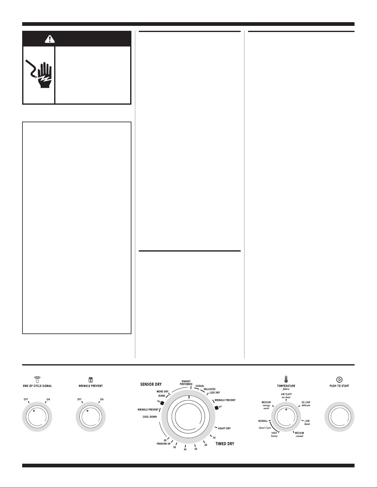
LESS DRY TEST
Begin with a fully assembled, empty dryer
with clean lint screen. Be sure dryer is
connected to a known good power source.
1. Set the following configuration:
■
Door - must be closed
■
Timer - Less Dry
■
Temperature switch - High
■
End of Cycle Signal switch - On
2. Press the Push to Start (PTS) switch.
After approximately 16 seconds, the
Timer will start to advance to the Off
position. If this function does not occur,
proceed to the Diagnostic Test.
DIAGNOSTIC TEST
This diagnostic test allows factory/service
personnel to test and verify all inputs to the
electronic control. The basic operation of this
test is to notify the operator with an audible
beep every time the status of an input to the
control changes state.
This test is performed with a fully assembled
dryer, connected to a known good power
source.
Activating the Test Mode
1. Set the following configuration:
Door - must be open
■
Temperature switch - Air Fluff
■
End of Cycle Signal switch - On
■
Timer - Timed Drying or Sensor Drying
■
selection
2. Turn the Wrinkle Prevent switch from Off
to On three times within a five second
period. A single beep, a pause, then a
single beep will sound to indicate that the
test mode is activated.
NOTE: If any of these initial conditions are
not satisfied, the control will not enter the
test mode.
Test Mode Functionality
When the control is in test mode, every input
change of state will result in an audible beep
(with the exception of the End of Cycle Signal
switch). This includes:
■
Door switch
■
Moisture Sensor (short/open Sensor
will result in a beep)
NOTE: A moistened finger or damp
cloth may also be used.
■
Temperature switch
■
Wrinkle Prevent switch
■
Push to Start (PTS) switch (with the
door switch closed)
■
Timer (any cam input change will result
in a beep)
NOTE: Timer will advance during test.
If any of the inputs do not result in a beep,
proceed to the corresponding component
tests, beginning on page 4.
FOR SERVICE TECHNICIAN’S USE ONLY PART NO. W10114943A
PAGE 2 TECH SHEET - DO NOT DISCARD
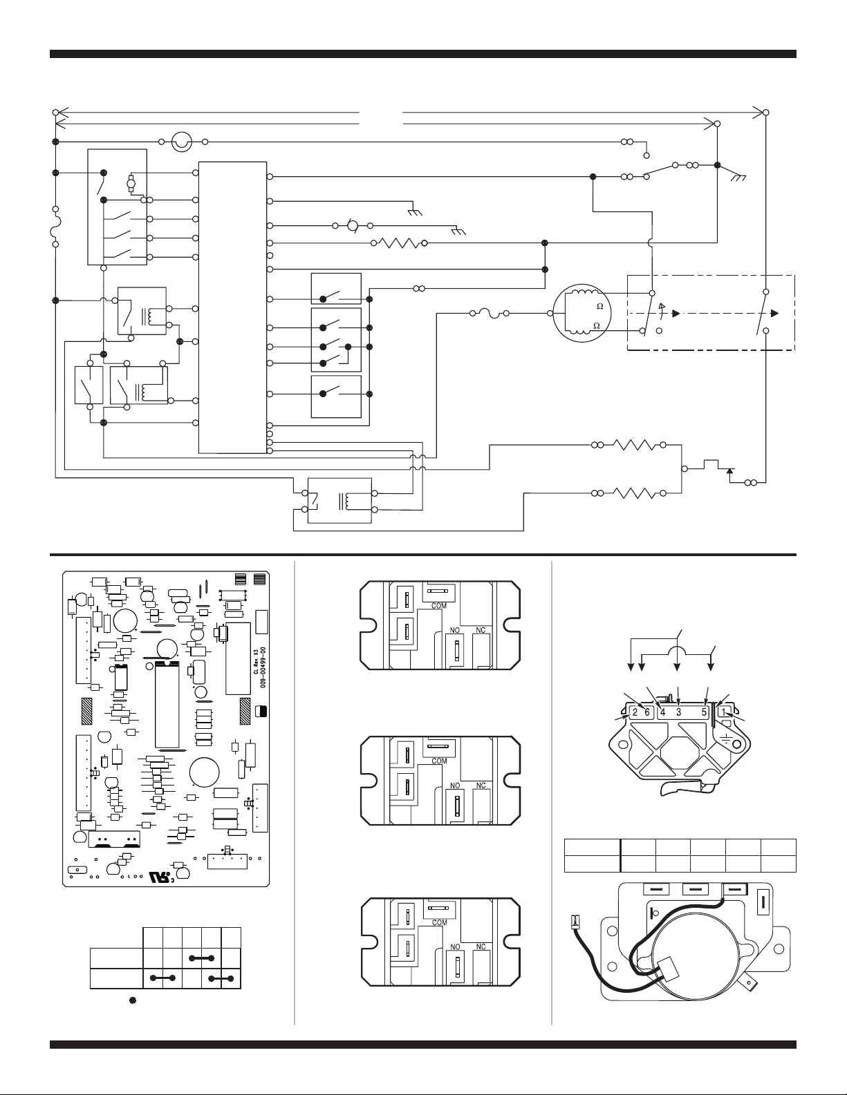
Electric Dryer Wiring Diagram
L1 LINE – BK – LINE L2R
BK
R
BK
R
TCO
310°F
(154°C)
R-W
R-W
PTS
TIMER
BU
BU
COM
BK
BU
NO
COM
BU
BK
BU
BK
HEATER
MOTOR
RELAY
BR
BK
RELAY
NO
BU-BK
DRUM LAMP
BU
V
R
W
PK-BK
DL
ELECTRONIC CONTROL
PT-1
TIMER
P1-1
MTR
P1-2
T2
P1-3
T3
P1-4
T4
P3-1
48 VDC
R-W
HEATER HI
R-W
HEATER
P3-2
LOW
48 VDC
P2-7
MOTOR
START
PK-BK
P1-5
START
SENSE
120 VAC RLY DR.
DOOR
MOIST
GND
MOIST.
TEMP.
MODEL
NEUTRAL
WPREVENT
FS-1
FS-2
FS-3
LOUD
MODEL
MODEL
L1-RTN
P2-6
P2-5
P2-4
P2-3
P2-1
P3-8
P3-7
P3-6
P3-5
P3-4
P4-4
P4-3
P4-2
P4-1
OR
G-Y
Y-R
R
W
GY
1
T
3
V
2
OR
1
1
T-W
HEATER RELAY
WRINKLE
PREVENT
SENSOR
FABRIC
SIGNAL
AC COIL
240 VOLTS
120 VOLTS
4
5
4
4
G-Y
THERMISTOR
10 kΩ
BR
BR
W– NEUTRAL
MAIN
2.4–3.6
START
2.4–3.8
1/3 H.P.
BU
W
5400 WATT
2700 WATT
EACH LEG
DOOR
SWITCH
5M
3M
CENTRIFUGAL SWITCH
6M
BU
W-R
W
BU
THERMAL FUSE
196 °F (91°C)
BU
DRIVE MOTOR
R-W
BR
NEUTRAL
TERMINAL
W
LINKED TO
CABINET
W
HIGH LIMIT
THERMOSTAT
180°F (82°C)
W
R
2M
1M
R
NC
7
4
PS02
1
8
PS03
5
1
14
Electronic Control Assembly
Contacts
Function
1M 2M 3M 5M 6M
Start
Run
=
Contacts closed
Centrifugal Switch (Motor)
Blue
PinkBlack
PT-1
PinkBlack
Blue
Motor Relay
Red-White
Drum Size:
7 cubic feet
Blue White
Black
Red
Drum Speed:
48 ± 3 RPM CW
Start Winding
Main Winding
Violet
Green-
Yellow
Red
Red-
White
1
Red-
White
Pluggable Drive Motor Switch
PS01
5
PS04
D.C. Heater Relay
Brown
Brown
A.C. Heater Relay
Red-White
Brown
Brown
Timer
Wire Colors
PT-1
BU BK R V W
Blue Black Red Violet White
R
W
U
K
V
DATE
B
B
Timer
PART NO. W10114943A FOR SERVICE TECHNICIAN’S USE ONLY
TECH SHEET - DO NOT DISCARD PAGE 3
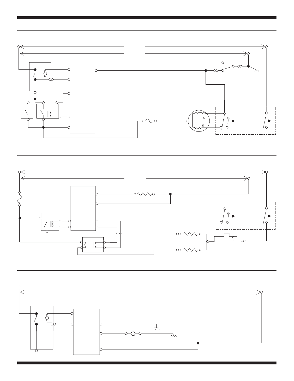
MOTOR STRIP CIRCUIT
L1 LINE – BK
TIMER
BK
BU
MOTOR
RELAY
BU-BK
PK-BK
NO
BU
BU
PTS
BK
BU
BU
BK
BU
COM
BK
HEATER STRIP CIRCUIT
L1 LINE – BK
THERMAL
CUT-OFF
(TCO)
310 °F (154°C)
R-W
COM
HEATER
RELAY
NO
BR
ELECTRONIC CONTROL
PT-1
P1-1
P3-2
P2-7
PK-BK
P1-5
TIMER
MTR
HEATER
LOW
MOTOR
START
START
SENSE
DOOR
ELECTRONIC CONTROL
NEUTRAL
48 VDC
HEATER
HI
HEATER
LO W
120 VAC
RLY DR
L1-RTN
HEATER RELAY
R-W
R-W
P3-1
P3-2
TEMP.
AC COIL
P2-6
P2-3
P2-1
P4-1
P4-2
W
R – LINE L2
NEUTRAL
TERMINAL
LINKED TO
CABINET
W
2M
1M
240 VOLTS
120 VOLTS
BU
THERMAL FUSE
196 °F (91°C)
W – NEUTRAL
BU
BU
2.4–3.8
DRIVE MOTOR
MAIN
2.4–3.6
START
1/3 H.P.
BU
DOOR
SWITCH
W
5M
CENTRIFUGAL SWITCH
6M
3M
R – LINE L2
240 VOLTS
120 VOLTS
THERMISTOR
R
W
BR
BR
10 kΩ
W-R
R-W
BR
W – NEUTRAL
5400 WATT
2700 WATT
EACH LEG
5M
3M
HIGH LIMIT
THERMOSTAT
180°F (82°C)
CENTRIFUGAL SWITCH
6M
NC
NEUTRAL
TERMINAL
LINKED TO
CABINET
R
2M
1M
MOISTURE SENSOR STRIP CIRCUIT
L1 LINE – BK
120 VOLTS
TIMER
BK
BU
ELECTRONIC CONTROL
BK
PT-1
BU
P1-1
TIMER
MTR
MOIST
GND
MOIST.
NEUTRAL
P2-5
P2-4
P2-1
G-Y
SENSOR
Y-R
G-Y
W
W – NEUTRAL
FOR SERVICE TECHNICIAN’S USE ONLY PART NO. W10114943A
NEUTRAL
TERMINAL
LINKED TO
CABINET
 Loading...