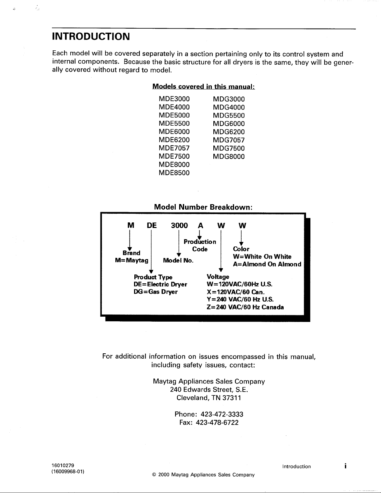
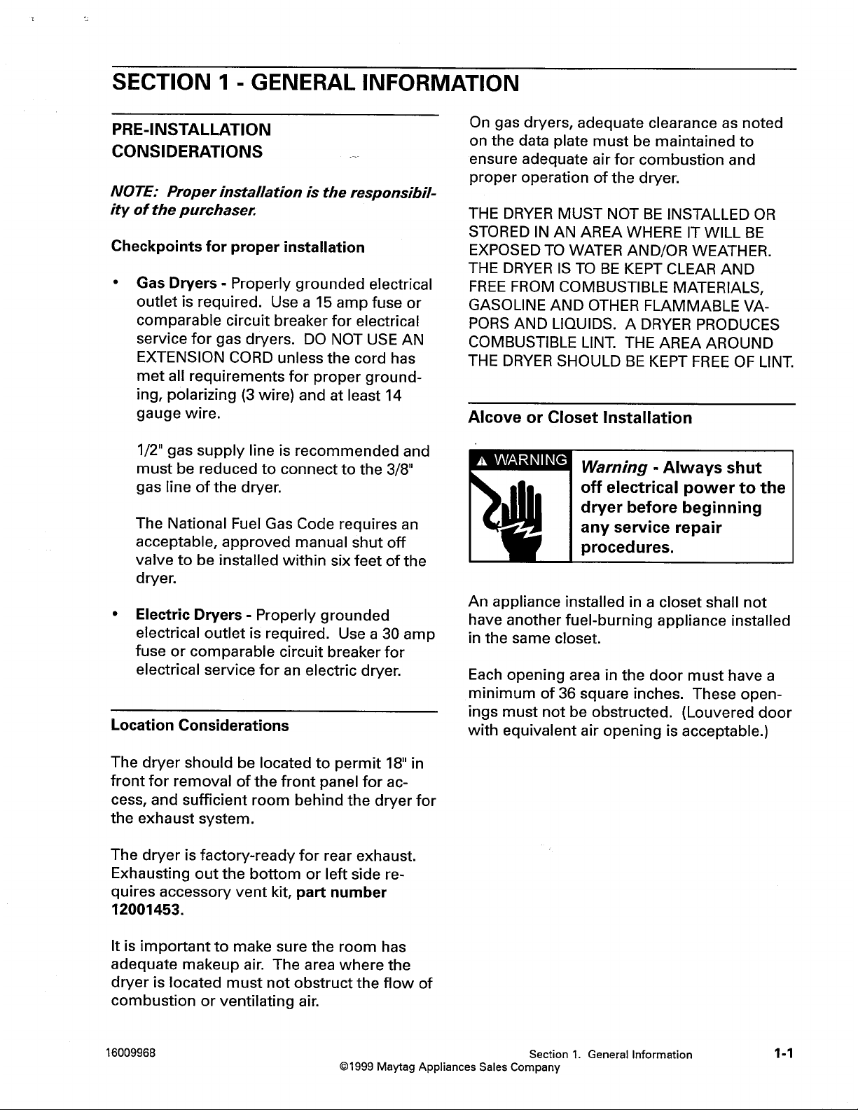
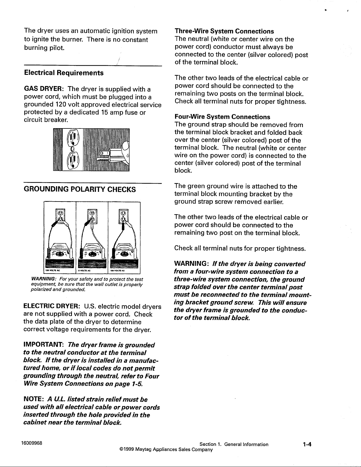
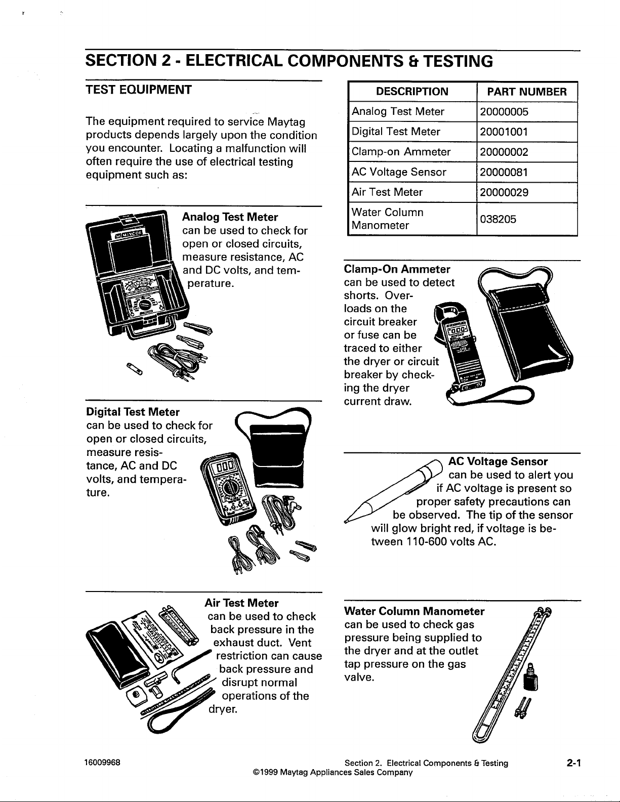
Q: What type of electrical socket should be installed for the gas dryer use?
A: The gas dryer use requires an electrical socket which is of proper grounding. A 15-amp fuse or its equivalent breaker is sufficient for the service supply.
Q: Gas Pressure required for the gas dryer?
A: Natural gas: 3.5 inches water column LP gas: 11 inches water column.
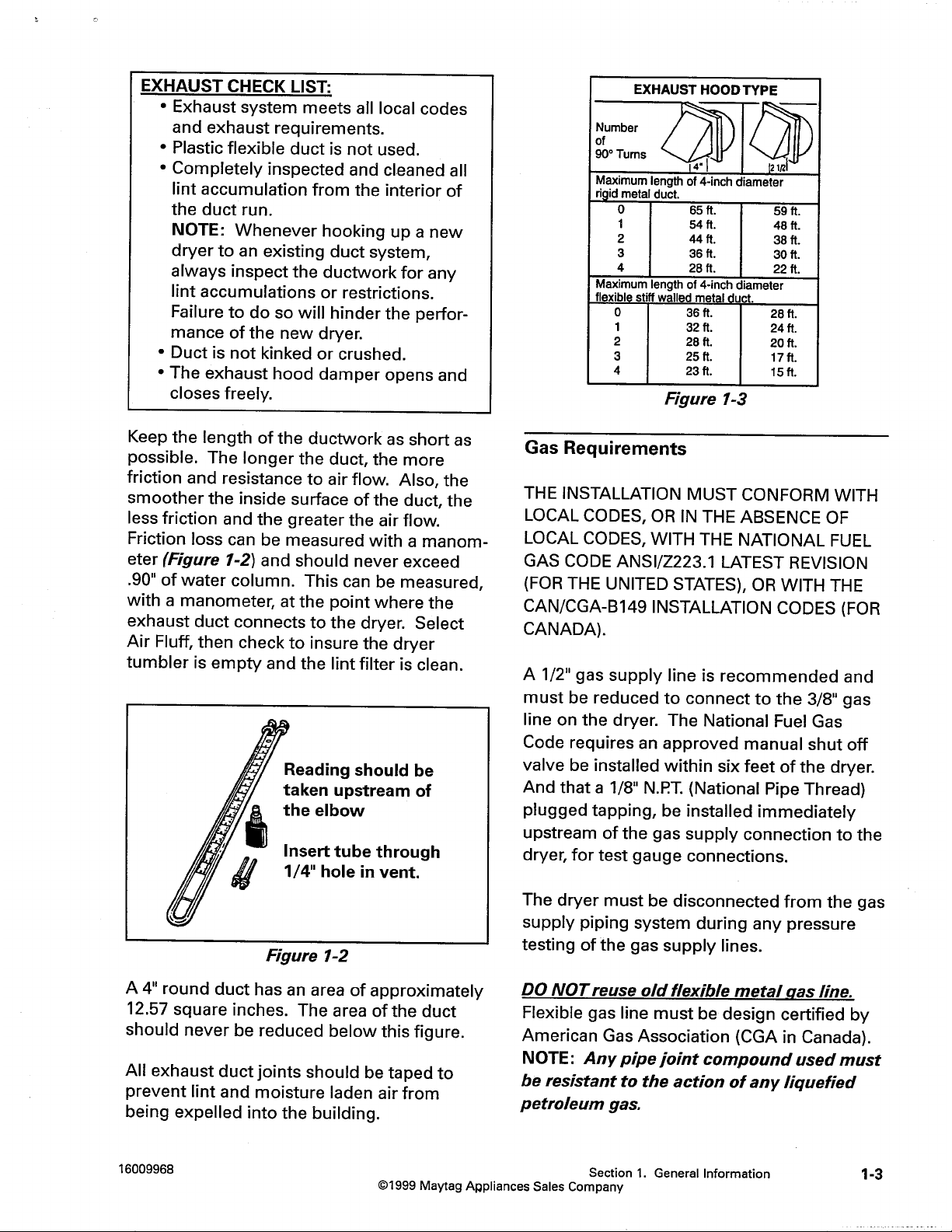
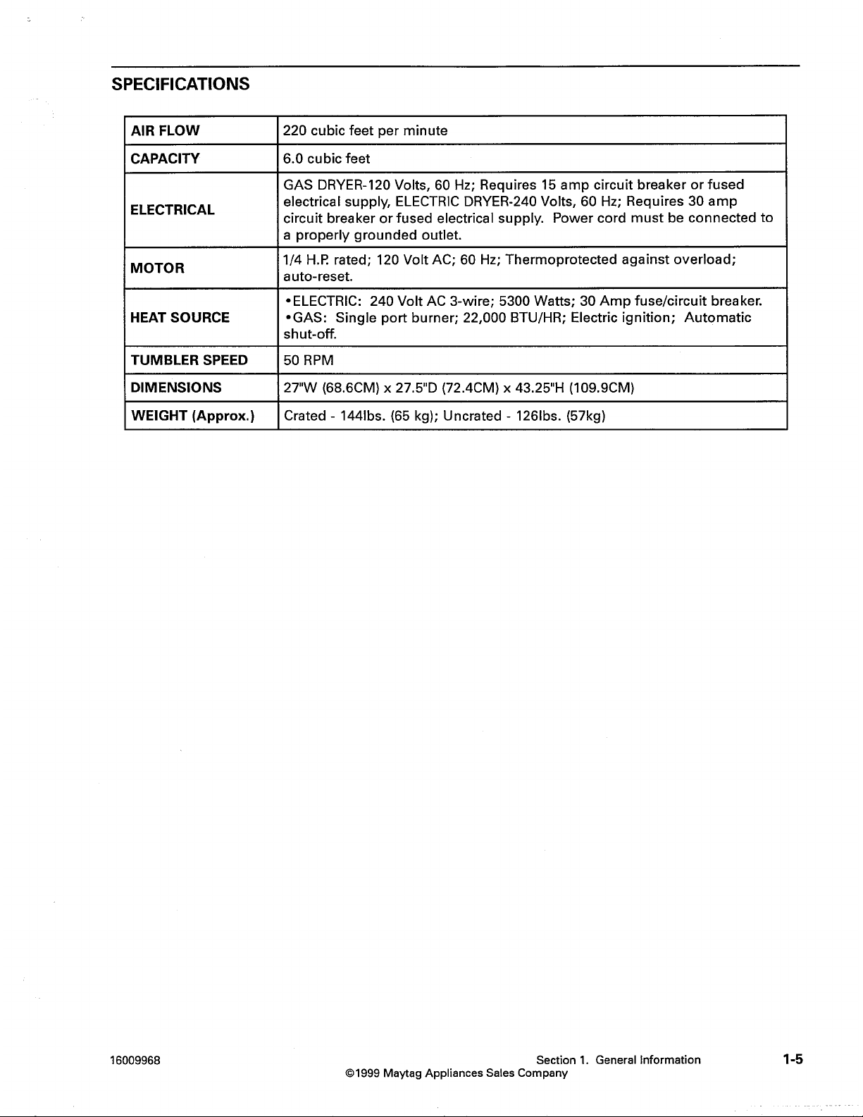
Q: What’s the airflow of the dryer?
A: The drier has a ventilation rate of 220 cubic feet every minute.
Q: What do the warranty details for this dryer include?
A: The warranty concerns have not been explained in the manual, for those concerns please contact the customer care of Maytag.
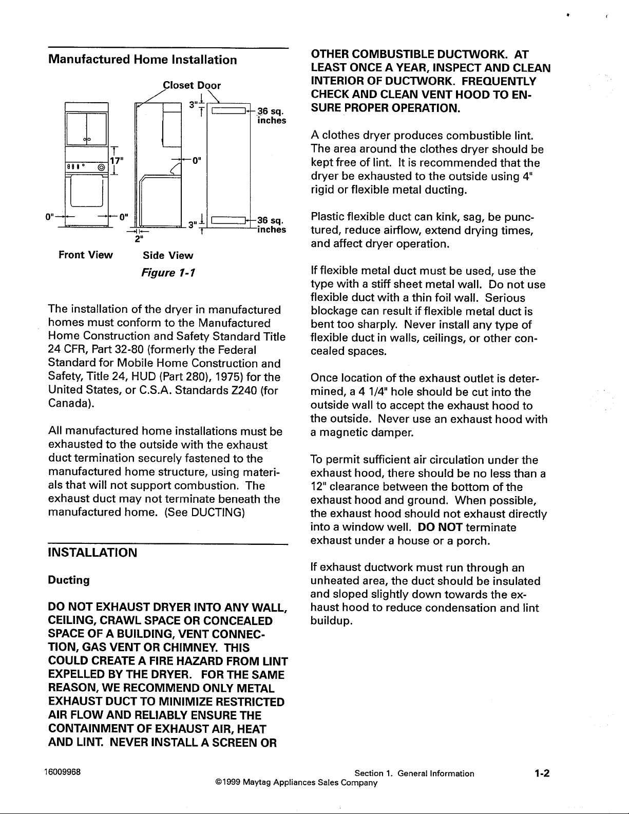
Q: Is it true that this drier is suitable to be used within a manufactured home?
A: Yes, but it has to meet the guidelines of us department of housing and urban development that includes the Construction and Safety Standards for the Manufactured Home.
Q: Is a power cord included for the electric dryer?
A: There's no power Cord supplied with the U.S electric model dryers, the installation expert has to bring their own.
Q: With how much frequency should one wash the lint filter?
A: The lint filter from the dryer should be removed after each and every use so that blockages are prevented and the dryer works efficiently.
Q: In case the drier won’t heat what should be done?
A: Inspect for a malfunctioning heating element, hi-limit temperature controlling device or wiring problems.
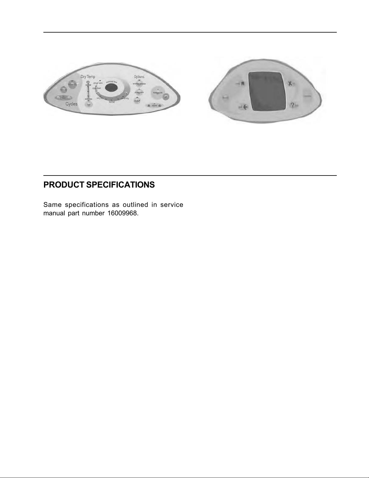
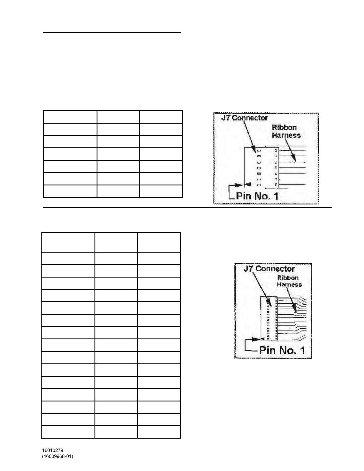
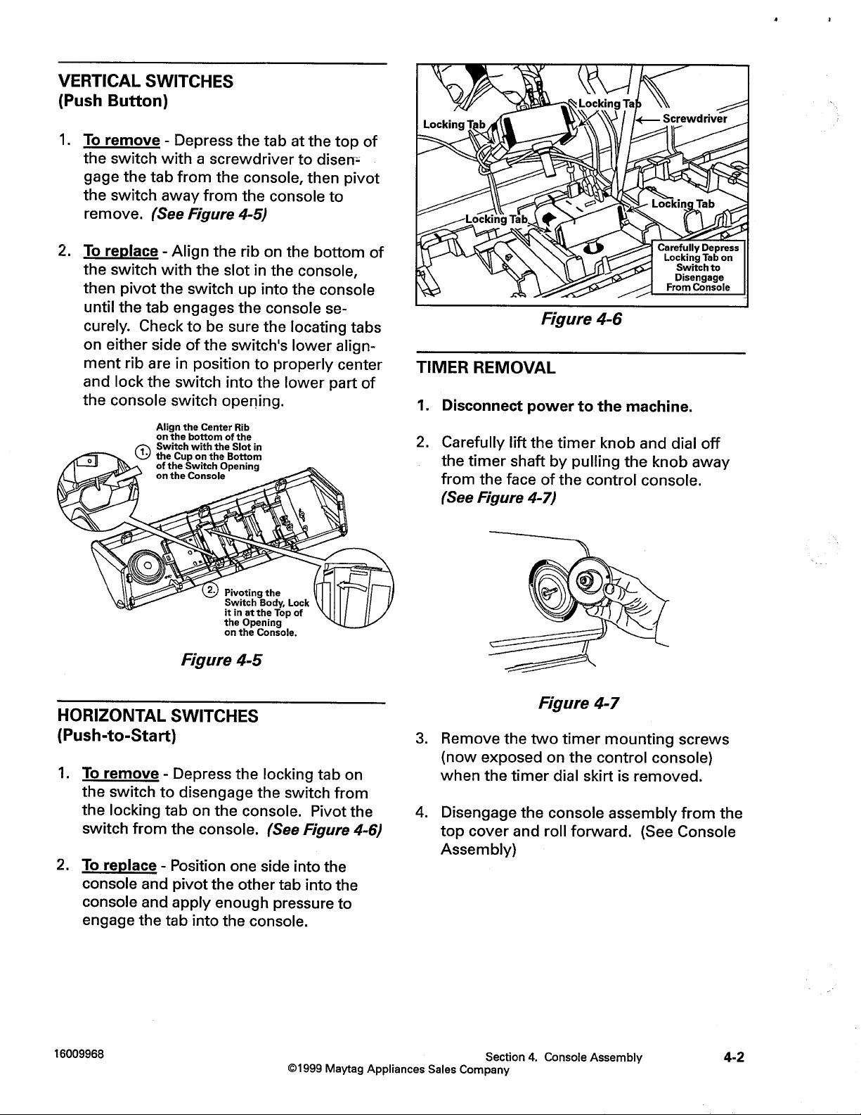
On the MDE/DG5500 dryer you can perform
the Membrane Pad Check with the control
console. (See Section 9: Accessing Service
Mode; Membrane Pad Check)
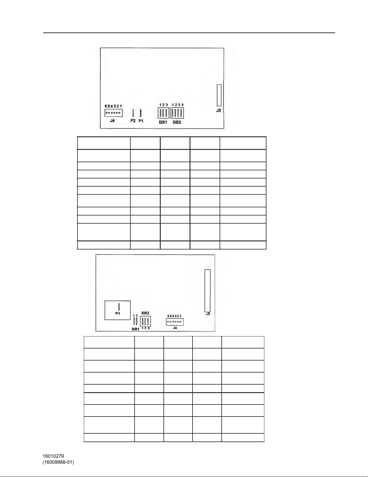
LCD Dryer
Membrane Pad Pin Number Pin Number
homeJ7(3)J7(5)
favoritesJ7(4)J7(5)
backJ7(3)J7(6)
start/pauseJ7(3)J7(7)
offJ7(4)J7(7)
helpJ7(4)J7(6)
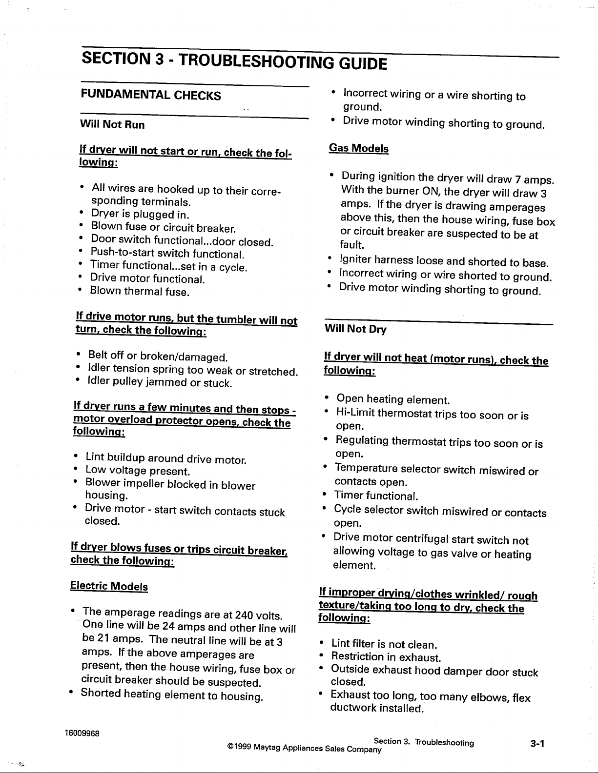
LED Dryer
On both dryers, you can check the membrane pads, by pulling the J7 connector from
the machine control board and locating the
corresponding switch pin numbers in the
ribbon harness.
Membrane
Pad
Pin Number Pin Number
sensor dryJ7(12)J7(13)
time dryJ7(11)J7(13)
time (+)J7(10)J7(13)
time (-)J7(9)J7(13)
Dry Temp (^)J7(11)J7(14)
Dry Temp (v)J7(10)J7(14)
Dryness(<)J712)J7(14)
Dryness(>)J7(9)J7(14)
wrinkle releaseJ7(11)J7(15)
press careJ7(9)J7(15)
air fluffJ710)J7(15)
start/pauseJ7(11)J716)
signal (-)J7(12)J7(15)
offJ7(9)J7(16)
signal (+)J7(12)J7(16)
16010279(16009968-01)
Section 2. Electrical Components & Testing2-8
Page 25
16023110
Page 26
16023110
Page 27
16023110
Page 28
Page 29
16023110
Page 30
16023110
Page 31
MODELS: MDE/DG5500, 7500
16023110
CONSOLE WITH MEMBRANE PAD
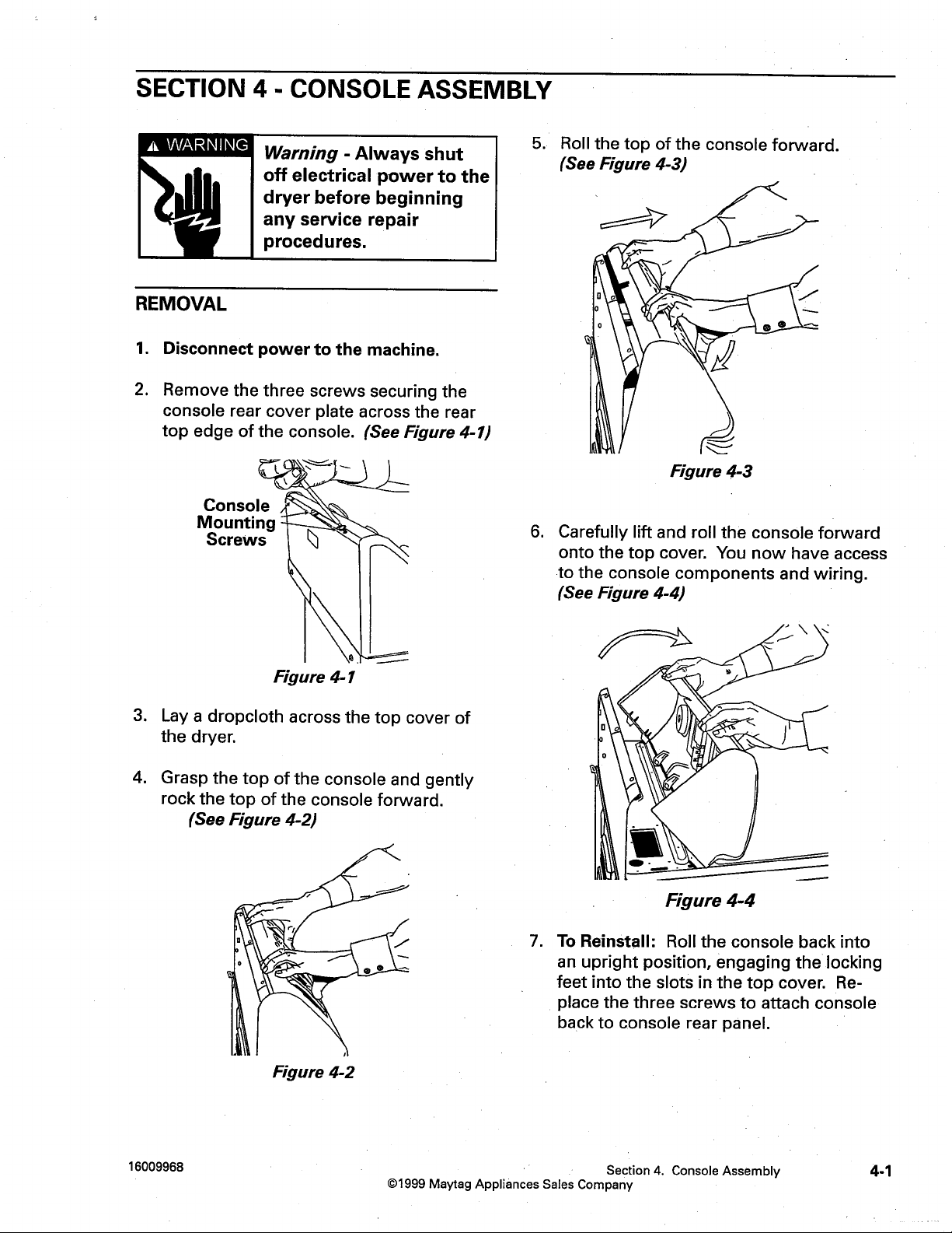
Warning - Always shut off
electrical power to the
dryer before beginning any
The replacement console assembly consists of
the console, medallion and membrane pad.
CONSOLE REMOVAL
1. Disconnect power to the unit.
2. Remove the four screws securing the
console to the rear cover plate.
5. For reinstallation, reverse the
aforementioned steps.
Figure 4-10
MICROPROCESSOR BOARD
REMOVAL
Figure 4-8
3. Lay a drop cloth across the top cover of the
washer.
4. Grasp the top of the console and gently
rock the top of the console forward away
from the rear console back. Note the
hooked tabs on bottom of the console,
which engage the slots in the top cover.
1. Disconnect power to the dryer.
2. Remove the console assembly.
3. Carefully remove the membrane pad
harness and other wires from the
microprocessor board.
Figure 4-11
16010279(16009968-01)
Figure 4-9
Section 4. Console Assembly
4-3
Page 32
16023110
Page 33
16023110
Page 34
16023110
Page 35
16023110
Page 36
16023110
Page 37
16023110
Page 38
16023110
Page 39
16023110
Page 40
16023110
Page 41
16023110
Page 42
16023110
Page 43
16023110
Page 44
16023110
Page 45
16023110
Page 46
16023110
Page 47
16023110
Page 48
16023110
Page 49
16023110
Page 50
16023110
Page 51
16023110
Page 52
16023110
Page 53
16023110
Page 54
16023110
Page 55
16023110
Page 56
16023110
Page 57
16023110
Page 58
SPECIAL FEATURES
16023110
The LCD and LED dryers come with several
new features not available with the earlier
versions of the Neptune dryers. By pressing
a combination of keys, the dryer can be
placed into an Advertising Mode or into a
Service Mode for the service technician.
ADVERTISING MODE
This mode will continuously display the LEDs
on the keyboard or illuminate the touch
screen.
LED Dryer
Pressing the damp dry and sensor dry keys
for 5 seconds will start the washer in the
Advertising mode. No functions will be run
except illuminating the LEDs.
All the LEDs will light within 1.5 seconds in the
following order and repeat: start/pause, signal,
wrinkle prevent, wrinkle release, air fluff, damp
dry, less dry, normal dry, more dry, very dry,
cool down, wrinkle prevent indicator,
temperatures (regular, medium, low, extra low),
sensor dry, time dry, time(+), time(-), 7
segment display.
While in advertising mode, the display will
cycle through eleven screens. If the touch
screen or any key (except off) is pressed, the
advertising sequence will be interrupted and
the control will go to the Interactive State.
When this occurs, the user is able to navigate
through the control as normal (including
setting favorites, setting preferences, etc.),
but the machine will not be allowed to run a
cycle. The only methods of exiting the
advertising mode is to remove power from
the machine or to press and hold both the
help key and the favorites key for 5 seconds.
The off key will not be active in the service
mode.
After 5 minutes of inactivity in the advertising
mode, the control will time out and return to
advertising mode and the advertising
sequence will begin again. When the control
times out in this manner, any settings or
changes that the user had made while in the
advertising mode will not be remembered.
SERVICE /DIAGNOSTIC MODE
Enter and exit the advertising mode by using
the same 2 key sequence or unplug the
power cord.
LCD Dryer
This mode will continuously display the touch
screen on the keyboard.
Pressing the favorites and back keys for 5
seconds will start the dryer in the Advertising
mode. No functions will be run except
illumination of the touch screen panel.
This mode provides service personnel the
ability to verify the operation of the dryer.
The service mode can be implemented in the
middle of any dry cycle. While in the service
mode, the servicer can start special service
tests such as a system check mode,
membrane pad check, display software
revision number and display diagnostic/help
code listings. (See Service Mode Table) The
diagnostic/help code information displayed
provides information about the machine.
Section 9. Dryer Controls Overview
9-6
Page 59
To aid the service technician, special software
16023110
was incorporated into the control boards of
the MDE/DG5500 & MDE/DG7500 dryers. The
software is used to monitor several functions
of the dryer during operation and identify any
abnormalities as they arise. These
abnormalities can be monitored in the
Service Mode and the board will list
previously identified failures as either a Help
or a Diagnostic code.
Press KeysSpecial Test/Function
wrinkle
release
dryer
temp(^)
dryer temp(v)
Diagnostic Codes
Sequences up the
help/diagnostic code list
Sequences down the
help/diagnostic code list
The Diagnostic codes are identified when the
severity level of the abnormality detected is
higher and service may be required.
Both code lists are stored in separate
permanent memories with a maximum of
nine codes per list.
NOTE: Due to the various differences
in the two dryer control systems, the
following pages will focus first on the
LED dryer then the LCD dryer.
LED DRYER
Accessing Service/Diagnostic Mode:
Pressing down the damp dry and time (-) keys
for 5 seconds places the machine in the
diagnostic mode.
time (-)
very dry(<)
start/pause
Displays Software Revision
Number
View current cycle
temperature (Co)
Start or pause cycle running
but remain in Diagnostic
mode
Diagnostic Codes:
When a problem with the dry system is
detected a diagnostic code is assigned and
logged into the control board memory. An
assigned diagnostic code indicates the dryer
may need to be serviced. The control board
will not log mulitple same codes per cycle,
however, it will log as many diagnostics as
possible for the machine to continue running.
See the diagnostic code table for specific
actions or references to where the proper
action is defined. (See page 15)
Accessing Diagnostic Codes
After the machine is in the diagnostic mode,
a ‘d’ will display and let the technician know
they are in the diagnostic mode. Pressing the
wrinkle release key will access the diagnostic
codes.The diagnostic codes can be viewed by
using the temperature (^) & (v) keys.
SPECIAL TESTS
The following table lists the various tests
available while in the Service Mode, which
can be accessed by pressing the following
keys:
list one each time it is pushed with no wrap.
The first time the down arrow key is pushed
the display will sequence to the next code
logged. The last code being displayed being
the oldest code. The up arrow will sequence
up the list one code each time it is pushed
until it reaches the top code. If there are no
diagnostic codes available, ‘00‘ will be
displayed for the diagnostic code.
This mode will allow the various inputs and
outputs to be controlled and viewed by the
technician by pressing individual keys. If no
activity is seen for 5 minutes after a key is
depressed, the control will reset back to the
normal mode. If no further activity is seen
after an additional 5 minutes the washer will
turn off. The following table lists the various
functions based upon on keys being depressed.
There will be no multiple occurrences of
either a diagnostic code or help code generated in the same cycle reported on the list.
But if the same code occurs in repeated
cycles, it will be registered.
To clear the diagnostic code list press
wrinkle prevent and very dry (>) for 5
seconds while viewing the list.
System Check Mode
While in diagnostic mode, pressing the damp
dry and signal (+) keys for 2 seconds, will
put the dryer into the system check mode.
"SC" will display.
Key Pressed: Function Performed
Enable sensor dry circuit.
(sense dry LED) When short
sensor dry
start/pause
dry temp(^)
very dry(<)
circuit is detected across the
sensor bars the normal dry
LED will turn on.
Cycles the motor relay
on/off. When the motor is
running the start/pause LED
is on.
If motor is running, cycles
the heater/gas valve on/off.
When the heater is regular
temp LED is on.
View current cycle
temperature (Co)
Membrane Pad Check
While in system check mode, pressing the
damp dry and sensor dry keys for 5 seconds,
will start a membrane pad switch test.
The membrane check involves turning all the
embedded LED on the membrane pad on.
All the LED’s can be toggled off by pressing
the key associated with the LED. To exit the
test at any point, press the damp dry (>) &
sensor dry keys again for 5 seconds or press
the off key to exit diagnostic mode.
Press and hold the back and help keys for 5
seconds to start the Service Mode.
Pressing the Service Mode keys again, will
take the machine out of the Service Mode.
Service Mode
diagnostic codes
user interface test
system check
exit service mode
1...
2...
3...
4...
upper
left
Touch the four corners and center of the touch
lower
left
User Interface
Test
screen in any order.
center
exit user
interface test
upper
right
lower
right
This will check the touch screen. The service
technician is prompted to “Touch the four
corners and center of the touch screen in any
order." When each area is pressed, the
display will reverse image. If all areas are
sensed, the control will display “Touch screen
test passed." If any area(s) is not sensed
within 5 seconds, the technician will be
prompted to “Touch the area(s) not
highlighted." If the area can still not be
sensed within 5 seconds, the control will
display “Touch screen test failed." In either
case scenario, the screen will step to the next
screen to check the membrane switches.
The Service Mode screen lists four different
touch panels; user interface test (membrane
switch test), system check, diagnostic codes
and exit service mode. Pressing any of the
touch screens will activate a different screen
dedicated to that function.
The diagnostic codes listed are the last four
codes assigned by the dryer.
After 5 minutes of inactivity in Service Mode,
the dryer will exit Service Mode and return to
the state just prior to Service Mode. If a
service test is being run, the control will
remain in Service Mode until 5 minutes of
inactivity has occurred at the end of this
cycle.
This test checks the membrane switches on
the console pad.
The screen displays the status of the touch
screen test that was just performed. The
Section 9. Dryer Controls Overview
9-9
Page 62
16023110
Page 63
16023110
Page 64
The membrane check turns all the embedded LED’s on.
ys
DRYER CONTROLS MDE/MDG6800, MDG5500
16023110
Control Configuration
This Trouble Shooting guide illustrates how the software
works with the 13 and 15 key membrane switches. The
section on Accessing Diagnostic Codes includes
instruction for use with older control boards.
13 Key Membrane
15 Key Membrane
Service Mode
This mode provides Service Personnel the ability to
verify the operation of the dryer.
The Service Mode can be implemented in the middle of
any dry cycle. While in the Service Mode, the
Technician can start special diagnostic tests such as a
System Check Mode, Membrane Pad Check, Display
Software version number and display diagnostic/help
code listings.
Enter Service Mode:
Air Fluff
Press
and
Time (^)
- 13 Key Membrane.
or
Air Fluff
and
Time (+)
- 15 KeyMembrane.
keys for 3 seconds, or until a beep is heard. The
machine will now be in Service Mode and “d” will be
displayed.
Exit Service Mode
Press the
Air Fluff
Diagnostic Tests
OFF
key to exit Service Mode or repeat the
Time (+)
and
sequence.
The following table lists the various tests available while
in the Service Mode, which can be accessed by
pressing the following keys:
Key Press Special
Test/Function
Wrinkle release
Then press
Temperature (^)
or
- 13 Key
Dry Temp (^) - 15 Key
Display list of
diagnostic codes.
To sequence thru
the diagnostic
and help codes.
Time (v)
- 13 Key
or
Time (-)
- 15 Key
Sensor Dry Level (^)
Key
or
Very Dry (<) - 15 Key
Display revision
number
View current
- 13
cycle temperature
in Celsius
Key Press Special
Test/Function
Start/Pause
Start or pause
cycle running but
remain in
diagnostic mode.
System Check Mode
While in Service Mode, pressing the
Air Fluff and Signal (+) - 13 Key Membrane
or
Air Fluff
and
Signal (+)
- 15 Key Membrane
keys for 3 seconds, will put the dryer into the System
Check mode and "SC" will display. The following table
lists the various functions based on the keys being
pressed.
System Check Mode Table
Key Pressed: Function
Performed
Sensor Dry
Enable sensor
dry circuit (sense
dry LED) when
short circuit is
detected across
the sensor bars
the normal dry
LED will turn on.
Start/Pause
Cycles the motor
relay on/off.
When the motor
is running the
start/pause LED
is on.
Temperature (^)
- 13 Key
or
Dry Temp (^) - 15 Key
If motor is
running, cycles
the heater/gas
valve on/off.
When the heater
is regular temp
LED is on.
Sensor Dry Level (^)
Key
or
View current
- 13
cycle temperature
in Celsius.
Very Dry (<) - 15 Key
Membrane Pad Check
All the LED’s can then be toggled off by pressing the
key associated with the LED.
While in System Check Mode, pressing the
Air Fluff and Sensor Dry - 13 Key
or
Air Fluff
Sensor Dry
and
- 15 Key
keys for 2 seconds, will start a Membrane Pad Switch
Test. To exit the test at any point, press the same ke
again for 2 seconds or press the
The Diagnostic Codes are identified when the severity
level of the abnormality detected is higher and service
may be required.
When a problem with the dryer is detected a Diagnostic
Code is assigned, and can be displayed. The Control
Board will not log multiple same codes per cycle;
however, it will log as many Diagnostics as possible for
the machine to continue running.
Accessing Diagnostic Codes with 13 Key Membrane
Press Air Fluff and Time (^) to enter Service Mode.
Press the Wrinkle Release key to access the
Diagnostic Codes. Scroll through the Diagnostic Codes
by pressing the Temperature (^) key. The first time the
key is pressed the newest code will be displayed. Each
additional key press shows the next code. Once all the
codes have been displayed a “d” is displayed and the
process repeats. If there are no Diagnostic Codes
available, “00” will be displayed for the Diagnostic Code.
Accessing Diagnostic Codes with 15 Key Membrane
Press Air Fluff and Time (+) to enter Service Mode.
Press the Wrinkle Release key to access the
Diagnostic Codes. Scroll through the Diagnostic Codes
by pressing the
Temperature (^)
. The first time the key
is pressed the newest code will be displayed. Each
additional key press shows the next code. Once all the
codes have been displayed a “d” is displayed and the
process repeats. If there are no Diagnostic Codes
available, “00” will be displayed for the Diagnostic Code.
There will be no multiple occurrences of either a
diagnostic code or help code generated in the same
cycle reported on the list. But if the same code occurs in
repeated cycles, it will be registered.
Clearing Diagnostic Codes
To clear the diagnostic code list press
Air Fluff and Wrinkle Release - 13 Key
or
Air Fluff
and
Wrinkle Release
- 15 Key
for 3 seconds while in diagnostic mode.
Diagnostic Codes
Code Description Trigger Action Taken
Dryer Thermistor
1
Short Sensed
The
thermistor
resistance is
very low,
with a
temperature
> 175
degrees.
Check for:
-
Clogged lint
screen.
-
Restricted
vent system.
Failed thermistor.
Code Description Trigger Action Taken
Thermistor Open
2
Sensed
Door Circuit
3
Failure
Possible motor
4
transistor error
Not Used
5
Non Volatile
6
Memory
Stuck Key A key is
8
The
thermistor
resistance is
very high
Invalid state
for more
than 256
milliseconds
If either
motor
transistor is
seen open or
shorted
during
startup
Problem
Detected
with integrity
of
parameters
stored in
EEPROM
memory.
sensed to be
pressed
more than
75 seconds,
the key shall
be assumed
to be stuck.
Check for:
-
-
Loose or open wire
Check for:
- Loose or open wire
terminals in Door
Sense circuit.
Check for:
-
-
-
If relay does not
function, replace
machine control
Run membrane pad
check and replace
console w/membrane
pad if necessary.
Low ambient
temperature in
room (Below
50oF/10oC).
Outside vent
damper is stuck
open in
wintertime.
terminals
Loose
connections in
motor circuit.
Run System
Check Mode
and check the
motor relay
function.
If relay
functions,
Heater Relay Internal
Output
LI Board (input) BB1(1) BB2(3) 120VAC Door must be closed.
Motor
(input)
Neutral (input) BB2(2) BB1(1) 120VAC
Door Sense BB2(3) BB1(1) 120VAC Door must be open
Thermistor J4(1) J4(2) 5VDC NTC
This mode provides Service Personnel the ability to
verify the operation of the dryer.
The Service Mode can be implemented in the middle of
any dry cycle. While in the Service Mode, the
Technician can start special diagnostic tests such as a
System Check Mode, Membrane Pad Check, Display
Software version number and display diagnostic/help
code listings.
Removing A Favorite Cycle
If the consumer wants a favorite cycle removed, see
below:
Press Help and Back Keys for 3 seconds or until a
beep is heard.
Exit Service Mode
Press the
exit Service Mode. After 5 minutes of inactivity in
Service Mode, the machine will exit Service Mode and
return to the state just prior to where the user first
entered Service Mode.
Yes
key orExit Service Mode on the display
OFF
Section 9. Dryer Controls Overview
return without
making changes
Making changes
9-15
Page 68
MDE/MDG7500, MDE/MDG9800
cancel cycle
Output Status
sensor circuit enabled
press PAUSE and select output below
16023110
User Interface
Enter User Interface and follow the directions on screen.
This test will check the Membrane Pads and Touch
Screen. The Membrane Pad and Touch Screen Test
must be completed in approximately 10 seconds or a
failure will be shown on the display.
Membrane Pad Test
After passing the Touch Screen Test a Membrane Test
will be performed.
This will check the Membrane Switch and display the
status of the Touch Screen Test that was just
performed. The user will be prompted to press the
following 5 membrane switches in any order” (i.e. home,
favorites, back, help
off
(i.e.
) should not be pressed. Pressing the
and
start/pause
). The sixth key
off
key will
shut down the machine. If all keys are pressed,
“Membrane switch test passed” will be displayed. If any
key(s) are not pressed within 5 seconds, the user will be
prompted to “Touch the key(s) that are not highlighted”.
If key(s) again are not pressed within 5 seconds, the
display will show which key(s) failed.
System Check Cycle Not Running
System checks can be performed whether the dryer is
in a dry cycle or not. If the dryer
is not
in a dry cycle, the
display screen will allow the technician to toggle various
components On/Off. The screen will also display the
current status of the component inputs to the control
board.
toggle motor
toggle heater (if
motor is running)
toggle sensor
circuit
exit system
check
System Check Cycle Running
If the dryer is already running a cycle and the system
check is activated, then the screen will display the
status of all the outputs and inputs to the control board.
cancel cycle: This will stop the current cycle.
exit system check:
This will exit the system check
screen and revert back to the previous screen shown on
the display panel.
To toggle outputs,
motor on
heat on
Input Status
damp dry sensed
normal dry sensed
short circuit sensed
door closed
drum temperature
ambient temperature
exit system
check
Diagnostic/Help Codes
Displays all the diagnostic codes and how many cycles
ago the codes occurred.
Displays all the help codes and how many cycles ago
the codes occurred.
Heater Relay Internal
Output
LI Board (input) BB1(1) BB2(3) 120VAC Door must be closed.
Motor
(input)
Neutral (input) BB2(2) BB1(1) 120VAC
Door Sense BB2(3) BB1(1) 120VAC Door must be open
Thermistor J4(1) J4(2) 5VDC NTC


 Loading...