

Maytag DWU6402AAM, DWU6402AAE, DWU6750AAM, DWU6750AAE, DWU6750AAB Installation Instructions
...
240EdwardsStreet.SE
CleveJand.Tennessee37311
Tel:423-472-3333
Fax:423-478-671a
ELECTRICAl, REQUIREMENTS
CAUTION: DISCONNECT ELECTRICAL POWER BEFORE YOUSTART
ALL ELECTRICALWIRING AND GROUNDSHOULDBEDONE INACCOR-
DANCE WITHNATIONALAND LOCALCODES.
CAUTION: Toprevent accidentalcontact _th electrical connections,built-in dishwasher
models must not be connectedto a power source unlessthe dishwasheris completely
enclosed, withfront panels inplace. If the back or eitherside of the dishwasheris exposed,
a custom-madepanel must be used to completethis enclosure.
This dishwasheris designed foroperation on an adequatelywiredindividual 120 volt60 Hz
AC approved electricalcircuit. Use requiredfuse (15amp) orcomparablecircuitbreaker.
Two wire with groundservice to the dishwasheris recommendedfor connectionat the ter-
minal box and for grounding.
GROUNDING INSTRUCTIONS
: i
DANGER: To prevent the possibility of electrical shock, thisdishwasher as other electrical
appliancesmust be adequatelygrounded. It is the responsibilityof the installerat the point
of installation, taking into consideration local conditionsand requirements.
Cos_ome__e_ice __
240EdwardsStreet,SE
C;evetand,Tennessee272f_,
Tel:423-472-3333
Fax:423-478-671(]
This appliance must be connected to a grounded metal, permanent wiring system, or an
equipment-grounding conductor must be run with the circuit conductors and connected to the
equipment-grounding terminal or lead on the appliance. Or, if an external ground wire is
used, insert the wire through the cable clamp and attach it under the green grounding screw
in the wiring compartment. Attach the other end of the external ground wire to a suitable
external ground
POWER CORD INSTALLATION
If a power cord is provided, or is to be used, the power supply receptacle for the dishwasher
should be installed in the cabinet opening or on a wall adjacent to the undercounter space in
which the appliance is to be installed.
If the receptacle is located on an adjacent compartment, then the opening through the parti-
tion wall should be no more than 1 1/2" in diameter (38.1ram). If the partition wall is made
of wood, then the edges should be smooth and rounded. If the partition wall is metal, then
the edges MUST be covered using the grommet enclosed.
NOTE: Care should be exercised, when the dishwasher is installed or removed to reduce the
likelihood of damage to the power cord.
240EdwardsSVeet,SE
CieveJand.Tennessee37311
Tei:422-472-3333
Fax:423-478-67!0
PLUMBING REQUIREMENTS
CAUTION: DISCONNECT ELECTRICAL POWER BEFORE DOING ANY PLUMBING
CHECK LOCAL PLUMBING CODES FOR APPROVED PLUMBING PROCEDURES
AND ACCESSORIK$. ALL PLUMBING SHOULD COMPLY WITH LOCAL AND
NATIONAL CODES.
DRAIN
A 5/8 _ I.D. (Inner Diameter) x 7 ft. long, corrugated drainhose is positioned on the left side
ofthetub.
The drainconnectioncanbelocatedoneithersideofthecompartment.Elevatethedrain
hosetoa heightofatleast32"(81cm)abovethefloor.Forma loopinthehose,orattachit
toa formedreturnbendora drainairgapfastenedtothecabinet.
If the drain connection is to be made below the floor, the hose should be left in the looped
position. If it is necessary to slightly extend the drain hose to make the connection, DO NOT
reduce the drain hose to less that 1/2_ I.D.
DRAINING INTO A BRANCH TAILPIECE OR DISPOSER
If the dishwasher drain hose is connected to either a disposer or a branch tailpiece, remove
the hose from the side of the tub andform a loop 32" (81 cm) high in the sink compartment
or dishwasher cabinet opening. Connect to the disposer or tailpiece.
This loop must be maintained to prevent any kinks or restrictions. If necessary use available
accessory kit.
2.40EdwardsS[reet.SE
C[eveien&Tennessee37311
Tel:423-472-3333
Fax:_23--t78-6718
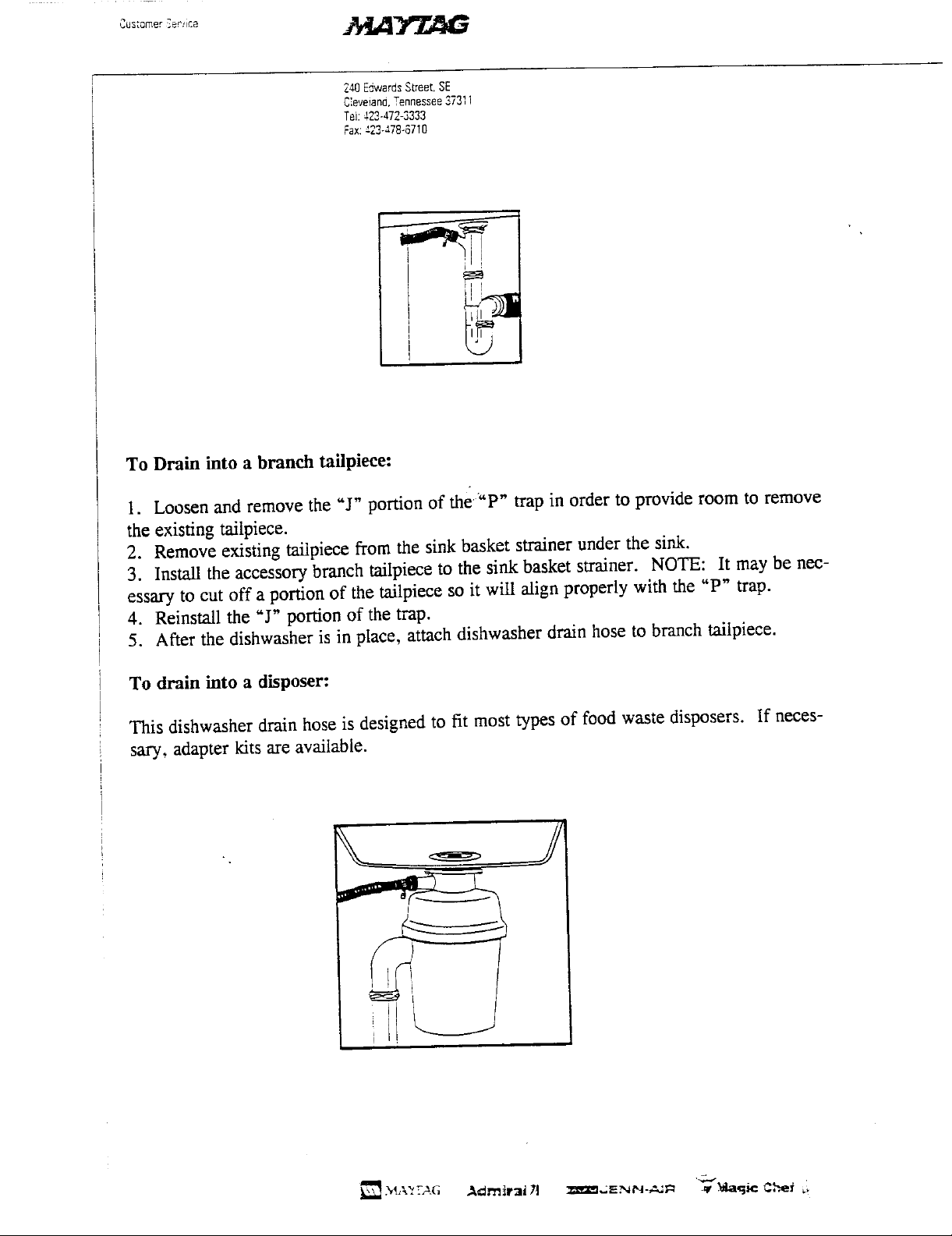
To Drain into a branch tailpiece:
1. Loosen and remove the "J" portion of the "P" trap in order to provide room to remove
the existing tailpiece.
2. Remove existing tailpiece from the sink basket strainer under the sink.
3. Install the accessory branch tailpiece to the sink basket strainer. NOTE: It may be nec-
essary to cut off a portion of the tailpiece so it wiU align properly with the "P" trap.
4. Reinstall the "J"portion of the trap.
5. After the dishwasher is in place, attach dishwasher drain hose to branch tailpiece.
To drain into a disposer:
This dishwasher drain hose is designed to fit most types of food waste disposers. If neces-
sary, adapter kits are available.
240EdwardsStreet.SE
C:eveiana.Tennessee37311
Tei:423472-3333
Fax:423-478-6710
DRAIN AIR GAP KIT (Accessory)
This accessory protects against a siphoning of water back into the dishwasher tub. It also
prevents a back-up of food waste into the dishwasher due to a plugged drain line.
When the drain hose is connected to an air gap, remove the hose from the side of the tub and
route it on a continuous incline from the pump to the air gap. (Coil excess hose and place it
in a safe place, perhaps under the dishwasher.)
If another type of air gap is required, such as to drain into the sink or for mounting behind
the back splash or into a wall, it should be purchased through a local plumbing source.
C°s_ome_Semite _e'L_ll _
240EdwardsStreeLSE
Clevelano.Tennessee,$7_,_1
Tel:423-_72-3333
Fax:423-a.78-6710
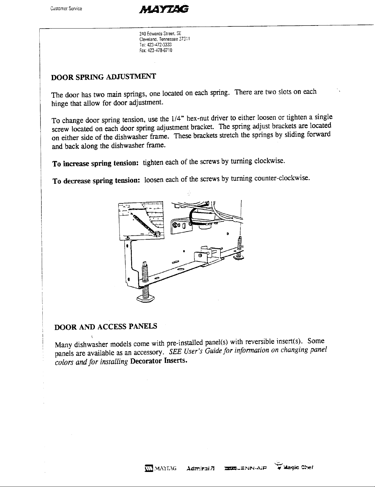
DOOR SPRING ADJUSTMENT
The door has two main springs, one located on each spring. There are two slots on each
hinge that allow for door adjustment.
To change door spring tension, use the I/4" hex-nut driver to either loosen or tighten a single
screw located on each door spring adjustment bracket. The spring adjust brackets are located
on either side of the dishwasher frame. These brackets stretch the springs by sliding forward
and back along the dishwasher frame.
To increase spring tension: tighten each of the screws by turning clockwise.
To decrease spring tension: loosen each of the screws by turning counter-clockwise.
DOOR AND ACCESS PANELS
Many dishwasher models come with pre-installed panel(s) with reversible insert(s), Some
panels are available as an accessory. SEE User's Guidefor information on changing panel
colors and for installing Decorator Inserts.
S r ,ce ./I IA
7_40EuwaresStreet,SE
C',eve!and,Tennessee37311
Teh422472-3333
Fax:423-478-6710
INSTALLATION
CAUTION: DISCONNECT ELECTRICAL POWER BEFORE YOU START.
START HERE...
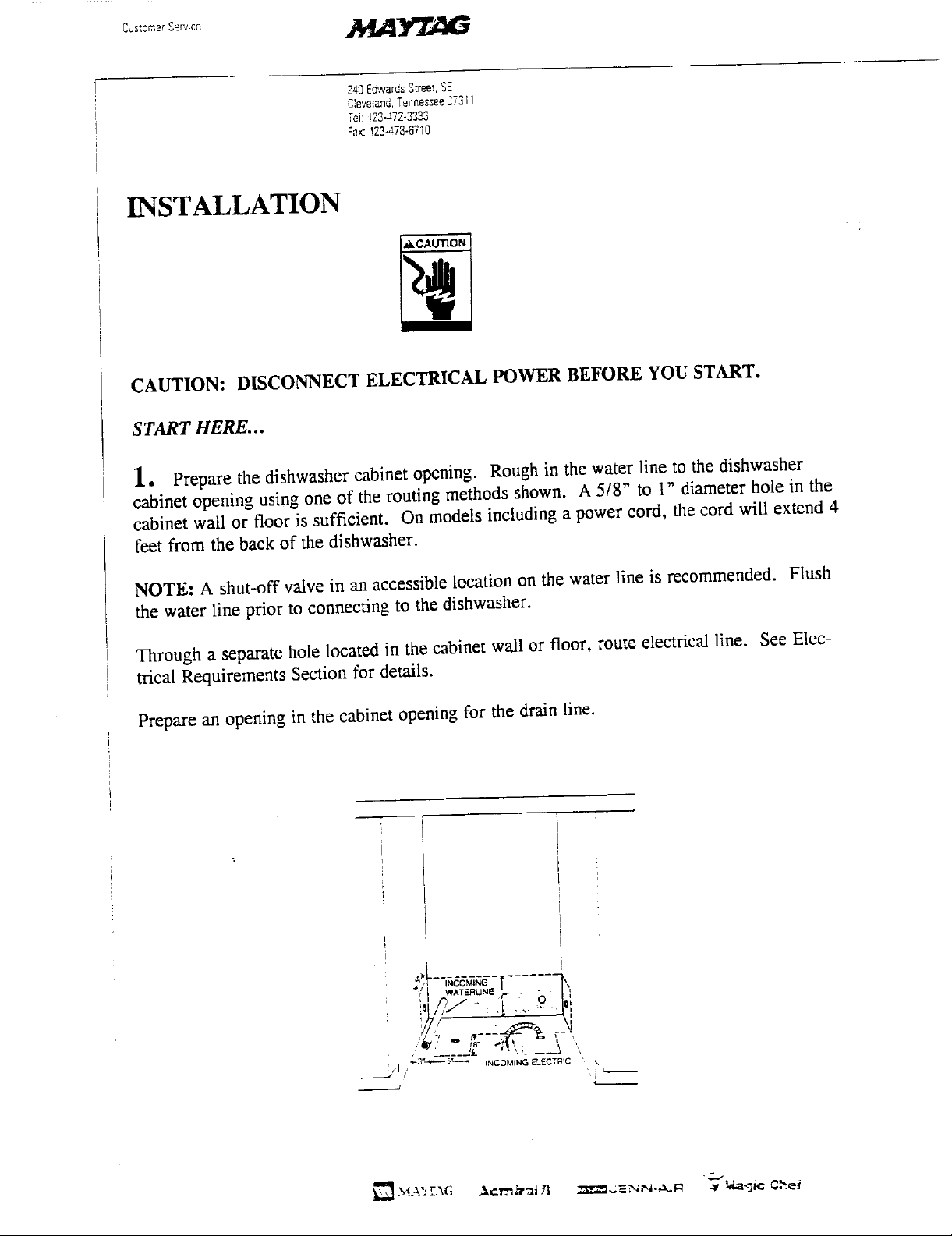
1, Prepare the dishwasher cabinet opening. Rough in the water line to the dishwasher
cabinet opening using one of the routing methods shown. A 5/8" to 1" diameter hole in the
cabinet wall or floor is sufficient. On models including a power cord, the cord will extend 4
feet from the back of the dishwasher.
NOTE: A shut-off valve in an accessible location on the water line is recommended. Flush
the water line prior to connecting to the dishwasher.
Through a separate hole located in the cabinet wall or floor, route electrical line. See Elec-
trical Requirements Section for details.
Prepare an opening in the cabinet opening for the drain line.
! t - 7" 0 i
_ WATERLINE _ • - _!_11
q. Q IF--± r- t
/ 1 _" INCQMING ELECTRIC ,_
/ '
t 1 ,

Z=0E_warasStreet,SE
Caveiand.Tennessee3731]
Te_:_23-472-3333
_x:422-478-_7;_
2. Position the dishwasher in front of the cabinet opening. Insert the drain hose into the ,,
hole in the cabinet wall. Begin to push the dishwasher back into the cabinet opening,
pulling the drain hose through the hole as you proceed.
With the dishwasher half way into the cabinet opening, make the required drainconnection or
position the drain hose for later connection. NOTE: If necessary, the support bar can be
removed for installation. But it must be reinstalled.
_._- of Dis '3£"

2_40EdwardsStreet,SE
C',eveian_.Tennessee37311
Tet:422-J.72-3333
Fax:422-478-87;O
3. Slide the dishwasher back in the cabinet opening. Position the dishwasher front flush '"
with the cabinets.
Slide the drain hose through the hole in the cavity. Prevent it from kinking.
LEVEL DISHWASHER .... The front legs align the front of the dishwasher vertically and
horizontally with the cabinet opening. The rear legs level the unit front to back and position
the mounting brackets.
A combination of the two adjustments are necessary to properly position the dishwasher, and
to insure proper fit of the door and latch. Disregard the square of cabinets - be sure the
dishwasher is level and solid. I.-
NOTE: With the door open use a level across the door and level horizontally.
@ o

2_0E=,;,arr,s S{reet,SE
C',eve!ar:3.Tennessee272_I
TeL3.72-'72-2333
Fax:-'2S478-6710
After leveling is completed, shim any gap between the mounting brackets and countertop.
Place shims between the countertop and dishwasher mounting brackets in the proper place so
the mounting brackets can be anchored to the countertop without twisting the tub. Trim
strips may be used on the sides if the cabinet space is not square to give the installation a fin-
ished appearance.
Open the door by lifting the latch. Make pilot holes in underside of counter and drive the
wood screws, provided in the accessory package, through the holes in the mounting bracket.
It may be necessary to provide an additional anchoring source for the mounting screws.
Where this is necessary, attach a mounting strip to the cabinet frame work.

2zO_::waresStreet.SE
C',ev_ancI,Tennessee3731i
Tei:=2_-.-t72-33_3
Fax:-t'22-a78-671O
4. With the dishwasher now in permanent position, connect the drain hose to the drain.
IMPORTANT: NEVER CUT THE CORRUGATED PORTION OF THE DRAIN HOSE.
All connections must be made on the rubber pomon of the drain hose. This hose can be sized
to fit any 5/8", 3/4" or 1" diameter connection. Cut the end at the pre-marked line as
required.
Routing of the drain hose is most important to insure satisfactory operation. NOTE: We do
not recommend that the drain line be extended beyond the7 feet of hose provided. However,
should this be necessary, it must always be attached to a line of larger inside diameter. DO
NOT route the house across the top of the tub. If a rubber hose is used as an extension to the
corrugated drain hose, all bends must be gradual to prevent kinking or collapsing of the hose.
The hose must be guided as the dishwasher is pushed intoplace in the cabinet.

Z40E,_wardsS[re_r,SE
Cieveian_,Tennessee373; ',
Tel:423-472-$333
Fax:423-478-6710
IMPORTANT: The hose may change position even after installation. To insure proper
operation, secure the hose to either side of the wall of the cavity, or to the tub with the hose
hook to assure a 32" loop. Make certain there are no kinks.
IMPORTANT: Do not attach the drain hose to any connection of smaller than 1/2" I.D.
From the 32" high drain loop as previously described, the drain hose can be routed and
attached to any type of drain source such as a disposer, branch tailpiece, separate trap, etc. in
accordance with local and national plumbing codes.
"4
5. With the water line flushed, connect the water supply line to the water valve and
tighten the fitting.
WATER HOOK-UP...To make the water connection, attach a 3/8" male compression or
flare elbow to the water valve andconnect to the incoming line, either 3/8 _ or 1/2_ O.D.
copper tubing. When installing the elbow to the water valve, thread sealing tape or pipe
threadcompound should be used. IMPORTANT: DO NOT connect a sweat _pe fitting
directly to the water valve as the required heat will damage the water valve.
Water

248EdwarasStreet,SE
C!eveiand.Tennessee27311
Tei:423-472-3333
Fax:423-478-67_0
6. Make the electrical connections. (See the Electrical Requirement Section).
',&CAUTION , ,
CAUTION: DISCONNECT ELECTRICAL POWER BEFORE STARTING.
ELECTRICAL HOOK-UP .... ELF_CTRICAL CONNECTIONS SHOULD BE DONE BY A
QUALIFIED SERVICE TECHNICIAN.
Remove the terminal box cover.
Remove the nut from the fitting and insert the wires and threaded portion of the fitting
through the hole on the back of the terminal box. Thread the lock nut onto the fitting and
tighten
Strip approximately 3/8" (0.9 cm) of insulation from the wires and connect to the wires from
the dishwasher wire harness located in the terminal box. Connect these wires using wire nuts
found in the accessory package, twisting and tightening securely over the wire connections.
Connect white to white and black to black.

2al3EdwardsS;reet.SE
C'.eveiand.Tennessee3731!
Tel:a.23_a72-3223
Fax:423-478-07:0
Attach the ground wire from the electrical service under the washer on the green grounding
screw. If an external ground wire is used, insert the wire through the cable clamp and attach
under the washer of the green grounding screw. Attach the other end of the external ground
wire to a suitable external ground. If a question arises, refer to your local electrical codes.
Tighten the two screws to secure the cable or conduit in the cable clamp.
Replace the terminal box cover.
On those models with a power cord, simply plug into receptacle. (See the Electrical
Requirement Section).
NOTE: The electrical schematic is located inside the access panel.
INSTALLATION CHECK
I. Check to be sure that electrical wiring and plumbing does not contact the motor or
blower (if equipped).
2. Turn on the hot water and electrical supply. Water temperature should be minimum of
140 degrees F. (60 C).
3. Operate the dishwasher through one cycle making sure it fills, circulates and drains.Check
for any leaks. Check the water level in the tub. It should fill the depression in the tub bot-
tom.
4. Install the access and toe panels.
5. Check the water hardness. Recommend using one teaspoon of detergent for each grain of
hardness.
6. LEAVE INSTALLATION INSTRUCTIONS AND USERS GUIDE WITH OWNER.

Cos_omer_e_ic_ .M,41Y'Z,aiG
240EdwarusStreet.SE
Cleveland.Tennessee37311
Tel:423-'72-3333
Fax:423-478-8710
Drain Hose
J
gBrackets Hose
Water Valve
Connection
(Not Shown)
- /
/
®
/
/
(4 L_,_,
,'/" Leveling Legs
240EdwardsStreet.$E
C',evetand._nnes_ee_7311
Td: 423-47E3333
Fax:423-478-871g
DISHWASHER PANEL
INSTALLATION INSTRUCTIONS
WARNING: Disconnect power before working on dishwasher! Installation should be done
by a qualified service technician.
Tools Required
1/4" Socket
Phillips Screw Driver
Permanent Marker
Rivet Gun (Optional)
Start Here
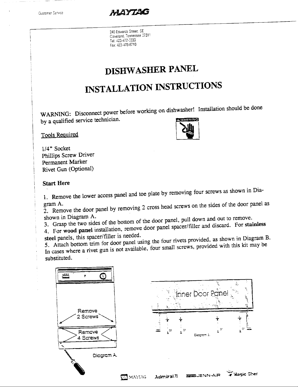
1. Remove the lower access panel and toe plate by removing four screws as shown in Dia-
gram A.
2. Remove the door panel by removing 2 cross head screws on the sides of the door panel as
shown in Diagram A.
3. Grasp the two sides of the bottom of the door panel, pull down and out to remove.
4. For wood panel installation, remove door panel spacer/filler and discard. For stainless
steel panels, this spacer/filler is needed.
5. Attach bottom trim for door panel using the four rivets provided, as shown in Diagram B.
In cases where a rivet gun is not available, four small screws, provided with this kit may be
substituted.
.... OI
":[nner r e!
• " -e'-i
Remave , ! e.. _t
L q
emove -- _ .. L
i -r _
[.
_,..'

240EdwardsStree[.S£
C;eveiand.Tennessee27311
;'el:423-472-$233
Fax:423-a78-_.7;0
6. Locate wires at the bottom right of the door panel and access area. Mark wires at the
bottom of the metal tub shield with a permanent marker. This mark will help insure the
wires are installed properly with the new wire shield.
Di¢cjr_rnC.
7. Remove screw holding plastic strap and discard strap and screw as shown in Diagram C.
8. Remove tub shield by removing one screw underneath, attaching it to the tub support,
shown in Diagram D.
L__///l;¢/ i
DicgrcmD.
9. Install new tub shield with screw. Assure the new tub shield is back against the tub and
that the tab fits into the tub support. Drive the screw from the bottom.
10. Place wire shield over wires as shown. Make sure all the wires are under the channel.
IMPORTANT! Wires cannot be pinched under the metal cover!
>d,,. :.-\G .._dr'nJr3J 71 _--Iz..;=--NN-,_M_ -_ 3da91¢ _-._ef
240EdwarasStreet,SE
C'_eveland.Tartnessee37311
Tei:-_22-a72-3333
Fax::23-a78-67!0
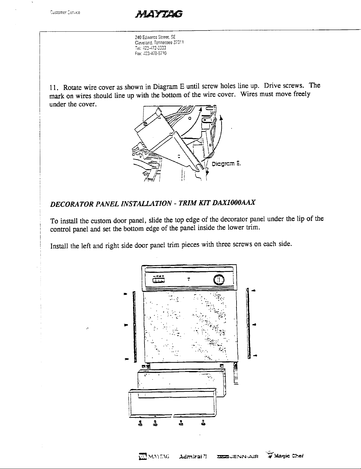
11. Rotatewire cover as shownin DiagramE until screw holes line up. Drive screws. The
mark on wires shouldline up with thebottomof the wire cover. Wires mustmove freely
under the cover.
o,o =m
DECORATOR PANEL INSTALLATION- TRIM KIT DAXIOOOAAX
To installthecustomdoor panel, slidethe topedgeof the decoratorpanelunder thelip of the
controlpanelandset the bottomedge of thepanelinsidethe lower trim.
Installthe left andright side doorpaneltrim pieces with three screwson each side.

Wood Pane/tnstattation tnstructions
Wood Door Panel _ :
Toinstallthe customdoor panel,slidethe top edge of ,, <
the decoratorpanelunderthe lip ofthe control panel
andset the bottomedgeof the panel insidethe lower
trim.
Installthe leftandrightsidedoor paneltrimpieceswith
threescrewsoneachside.
LowerAccess Panel __ _ m
providedinthe kit. The panelissecuredbythe chrome
Installthe decoratorpanel in the Iover access panel ! - _-+_=+i -_
trimpieceandscrewsprovidedwiththekit. l _°
& & & &
+'= 0
Wood Panel Dimensions
1/4"
+.6c_ +1]8,,
_ _ .3cm
1/4"
']+%_.+ ,]+ WoodDoor
_.3cm
,]8" + panet
183/16" .1.0cminthisarea
46.2cm _r _ 1"
1/8"_ /
45/8 II /'_""_ *"--_'
/
_+,_3/16"
3/8" max. thickness |
?'39/16"_59.8cm t
''" .,.- ,/,_ ,-+o._,_ O.+c,n
2.5crn
!iii¸_
i¸!i!:¸!_i
_i_i!ii_i_!_II!_II_!_
 Loading...