

Maytag 56326 Service Manual
r-
Side-By-Side
and
ToP
Mount
Refrigerator
Service
Manual
svF-0289
PRINTED
IN
U.S.A.
o Copyright
1989
--
,-a.
l..r
4--
,
,.-.-.-,=--:..
56326
]
INDEX
4-1
4-4
4-8
4-11
4-15
4-15
4-16
4-17
4-17
4-20
4-25
4-28
4-33
4-34
4-36
SaBIECT
SECTION
1
.
INTRODUCTION
SECTION
2
.
INSTALLATION
Specifications
Warranty
Installation
Instructions
Operation
SECTION
3. SERVICE
PROCEDURES
General
Checking
Operation
Leak
Testing
Leak
Testing
Yoder
LooP
Checking
Pressures
Evacuating
&
Recharging
Sealed
System
SweeP
Charge
SECTION
4 - COMPONENTS
Compressor
Heat
Exchanger
Condenser
Freezer
Evaporator
Electrical
System
Compressor
Overload
Protector
Starting
RelaY
PTC &
Run CaPacitor
Temperature
Oontrol
Defrost
Timer
Defrost
Heater
&
Thermostat
Condenser
Fan
Freezer
Fan
Divider Channel
Heater
SECTION
5
.
CABINET
& RELATED
COMPONENTS
Food
Liner
Compartment
Accessories
(shelves)
PAGE
SaBIECT
2-1
2-4
2-5
2-14
3-1
3-5
3-7
3-8
3-10
3-12
3-14
Meat
Keeper
5-3
Freezer
Cold
Control
5-4
Mounting
Hardware
5-6
Drain
Tubes
5-6
Styrofoam
Drip
Tray
5-7
Cabinet
Doors
&
Assoc.
Parts
5'9
Paint Touch-up
5-9
Door
Liner
5-9
Door Panel
S10
Reversing
Doors
$11
Top
Hinge
5-11
Door Closer
5-11
Shelf Guards
5'12
Cabinet
Wheels
5-12
Cabinet
Leveling
5-12
Gasket
Seal
5-13
Door
Switch
5-14
Water Components
5-15
Water
Supply
5-15
Water
Valve
5-15
Water Fill
Tubing
5-15
Water
Reservoir
S18
Fountain
Assembly
5-2O
lce &
Water
Fountain
5-20
lce &
Water
Actuator
Switch
5-21
Dash-Pot
5-22
Switch
Assembly
5-22
lce &
Water
Activating
Sw. +23
lce Dispensing
Safety
Door 5-23
Fountain
Heater
5-23
lce Storage
Bin
5-24
Interlock
Switch
5-24
Auger
5-25
PACE
SECTION6.ICEMAKER
lnstallation
Servicing
SECTION
7
.
TROUBLESHOOTING
SECTION
8
.
SCHEMATICS
sEcTroN
I - SPECIFICATIONS
6-1
6-10
5-1
5-1
MI\YTAG
SECTION
I
INTRODUCTION
GENERAL
This
manual covers
Maytag Refrigerators
manufactured beginning in 1989. Those
models
covered are
15, 17, 19, 20, 21,22,23
and
24
cubic
foot
Side-By-Side and
Top Mount
ref rigerators.
SAFETY
PRECAUTIONS
This
service information is intended to be used
by a
qualified
service technician, who is
familiar
with
proper
and safe
procedures
to
be followed when repairing any
electrical
appliance.
All fests and repairs should be
performed
by a
qualified
service technician,
using only Genuine Maytag
parts.
Repairs and servicing
attempted by uninformed
persons
can result in hazards
developing
due to improper assembly
or adjustment. While
performing
such
repairs,
persons
not
having
the
proper
background may
subject
themselves to
the risk
of
injury
or electrical
shock which can be
serious or even
fatal.
1-1
M/\YTAG
SECTION
2
INSTALLATION
SPECIFICATIONS
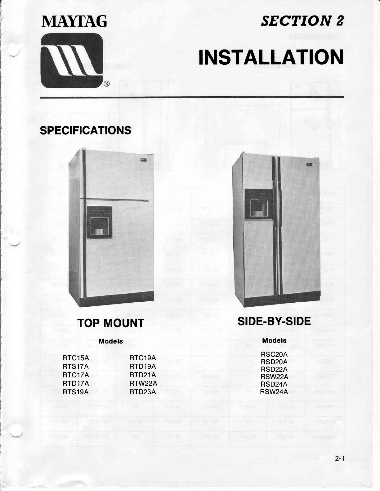
TOP
MOUNT
Models
SIDE.BY.SIDE
Models
RSC2OA
RSD2OA
RSD22A
RSW22A
RSD24A
RSW24A
RTC15A
RTS17A
RTC17A
RTD17A
RTS19A
RTC19A
RTD19A
RTD21A
RTW22A
RTD23A
2-1
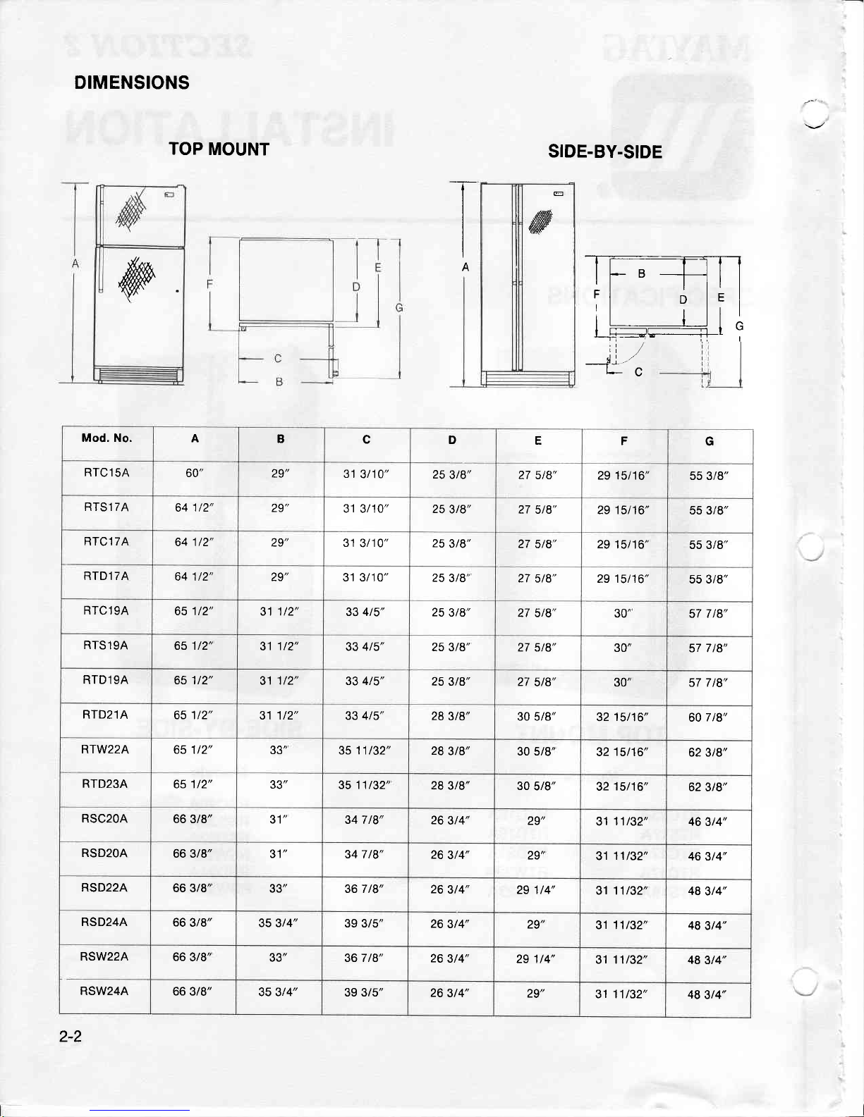
DIMENSIONS
TOP
MOUNT
SIDE-BY.SIDE
;i
*"1
L-C
ry
It-B--hrl
ri
o
le
I
:l ; lrl
lr
trln
I
r-----------------r-1
I
"
-i:
T
I
I
A
E
ffi
Mod. No.
A
B
c
D
E
F
G
RTC15A
60"
29"
31
3t10"
25
3t8"
27 5/8"
29 15t16"
55 3/8"
RTSl 7A
641t2"
29'
31 3/10"
25
3t8"
27 5t8"
29 15/16"
55 3/8"
RTCl7A
641/2"
29"
31
3/10" 25
3t8" 27
5/8" 29
15t16"
55 3/8"
RTD17A
64 1/2" ZJ
31 3/10"
25
3/8'
27 5/8"
29 15/16"
55 3t8"
RTC19A
65112"
31 1t2"
33 4t5"
25
3t8"
27
5t8"
30"
57 7
/8"
RTS19A
651/2'
31
1t2"
33 4t5'
25 3/8'
27
5/8"
erl"
57 7 l8'
RTD19A
65 1t2"
31
1/2"
33 4t5"
25 3t8"
27
5/8"
30"
57 7t8"
RTD21A
651t2"
31 1/2"
33 4t5"
28
3t8"
30 5/8"
32
15/16"
60
7 /8"
RTW22A
65 1t2"
33"
3511t32"
28
3t8"
30 5/8"
32
15t16"
62 3t8"
RTD23A
651/2"
33"
3511t32'
28 3t8"
30
5t8"
32
15/16"
62
3t8"
RSC2OA
66 3/8" JI
34 7 t8"
26
3t4"
29"
31
11t32"
46
3t4"
RSD2OA
66 3/8" JI
34 7 /8"
26
3t4" ZJ
31
11t32"
46 3t4"
RSD22A
66 3/8'
33"
36 7 t8"
26
3t4"
29 1/4"
3111t32"
48
3t4"
RSD24A
66
3/8"
35 3t4"
39 3/5"
26
3t4"
29"
31 11t32'
48
3t4"
RSW22A
66
3/8"
33"
36 7 /8"
26
3t4"
29 114"
31 11/32"
48 3t4"
RSW24A
66
3/8"
35 3/4"
39 3/5"
26
3t4"
29"
3111t32"
48
3/4"
2-2
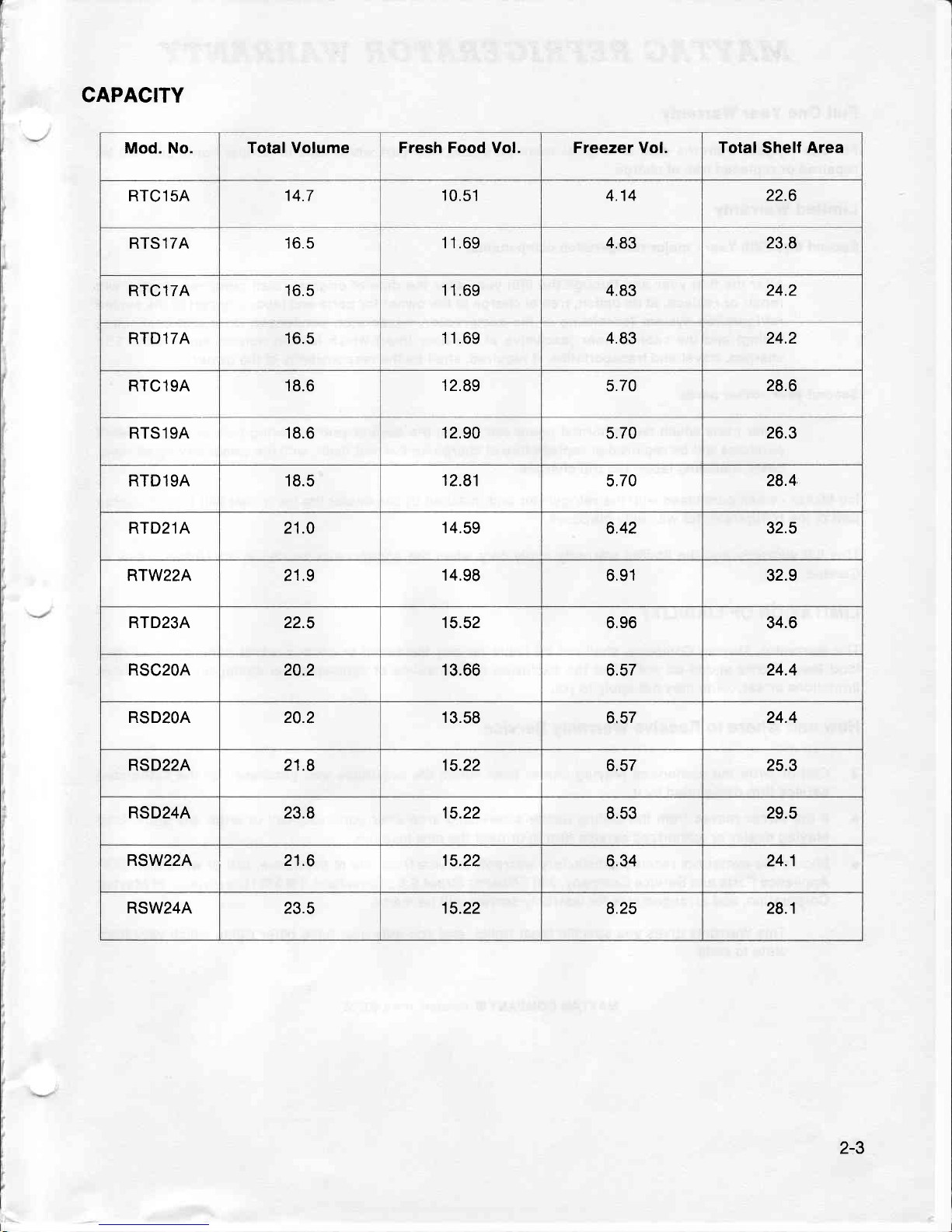
CAPACITY
Mod. No.
Total Volume Fresh Food Vol. Freezer Vol.
Total
Shelf
Area
RTC15A
14.7
10.51
4.14
22.6
RTS17A
16.5
11.69 4.83 23.8
RTC17A
16.5
11.69
4.83
24.2
RTD17A 16.5
11.69 4.83 24.2
RTC19A
18.6
12.89
5.70
28.6
RTS19A
18.6 12.90
5.70
26.3
RTD19A
18.5
12.81
5.70
28.4
RTD21A 21.0
'14.59
6.42
32.5
RTW22A 21.9
14.98
6.91 32.9
RTD23A 22.5 15.52
6.96 34.6
RSC2OA 20.2 13.66
6.57
24.4
RSD2OA 20.2 13.58
o.c/
24.4
RSD22A 21.8 15.22
6.57 25.3
RSD24A 23.8 15.22
8.53 29.5
RSW22A 21.6 15.22
6.34 24.1
RSW24A 23.5 15.22
8.25 28.1
2-3
MAYTAG
REFRIGERATOR
WARRANTY
Full
One Year
Warranty
For
one
(1) year
from the
date of
original retail
purchase,
any
part
which
fails
in
normal
home
use will
be
repaired
or
replaced
f ree
of charge.
Limited
Warranty
Second
thru Fifth Year
-
major refrigeration
components:
After the first
year
and through
the
fifth
year
after the
date
of original
retail
purchase
Maytag will
repair
or replace,
at
its
option, f ree
of
charge to the
owner for
parts
and labor
any
part
of the
sealed
refrigeration
system
(consisting
ol the
compressor,
evaporator,
condenser,
drier
and
connecting
tubing)
and the
cabinet liner
(exclusive
of the
door liner)
which fails
in normal
home
use. Trrp
charges,
travel
and transportation,
if required,
shall
be the responsibility
of the
owner.
Second
year
-
other
parts:
Other
parts
which
fail
in normal
home
use
during the
second
year
following
date
of original
retail
purchase
will
be
repaired
or replace
free
of charge
for the
part
itsell,
with
the
owner
paying
all
other
costs,
including
labor
and trip
charges.
lce Maker
-
when
purchased
with
the refrigerator
and installed
by the
dealer the
ice
maker
will
be considered
part
of the
ref rigerator
for
warranty
purposes.
This
full
warranty
and the
limited
warranty
apply
only when
the
appliance
is located
in
the
United
States
or
Canada.
LIMITATION
OF LIABILITY
The
warrantor,
Maytag
Company,
shall not
be liable
for
any incidental
or consequential
damages,
including
food
loss.
Some states
do not
allow
the
exclusion
or limitations
of
consequential
damages,
so
the
above
limitations
or
exclusion
may
not apply
to
you.
How
and
Where
to Receive
Warranty
Service
Call
or write the
authorized
Maytag
dealer
from
whom
the
appliance
was
purchased
or the
authorized
service
firm
designated
by
it.
lf
the
owner moves from
the
selling
dealer's
servicing
area
after
purchase,
call
or write
any
authorized
Maytag
dealer
or
authorized
service
firm
in
or near the
new
location.
Should
the
owner not
receive
satisfactory
warranty
service from
one
of
the
above, call
or
write
MAyCOR
Appliance
Parts
and
Service
Company,
240
Edwards
Street
S.E.,
Cleveland,
TN
97911,
a division
of Maytag
Corporation,
and
arrangements
for
warranty
service
will
be made.
This
Warranty
gives
you
specific
legal
rights,
and
you
may
also have
other
rights
which
vary from
state to
state.
2-4
MAYTAG
COMPANYO
Newton,
towa
50208
INSTALLATION
INSTRUCTIONS
ELECTRICAL
REQUI REM
ENTS
OBSERVE ALL NATIONAL ELECTRICAL
CODES AND
LOCAL
CODES
&
ORDINANCES
ELECTRICAL
SERVICE - 120 VOLTS,
60 Hz
ONLY
A 120 volt,
60 Hz, 15 ampere fused
electrical supply is required.
An
individual
branch
(or
separate
circuit serving only this
appliance
is
recommended.)
DO
NOT USE
EXTENSION
CORD unless it meets
all
requirements
as outlined for
grounding,
polarizing
(3-wire)
and
capacity. Wire
size should be
at
least No. 14.
BEFORE PLUGGING
lN POWER
CORD, OPERATING
OR TESTING,
Follow
grounding
instructions
in
Grounding
Section.
GROUNDING . 120
VOLTS, 60
HZ
IMPORTANT
SAFETY PRECAUTIONS
WARNING - To
prevent
unnecessary risk
of fire, electrical
shock
or
personal
injury,
all
wiring
and
grounding
must
be done
in
accordance
with National
Electrical
Code and local
codes
and
ordinances. lt is the
personal
responsibility
and obligation
of the appliance
owner to
provide
adequate electrical
service for this
appliance.
ELECTRICAL
GROUTVD 'S REQUIRED
ON THIS
APPLIANCE
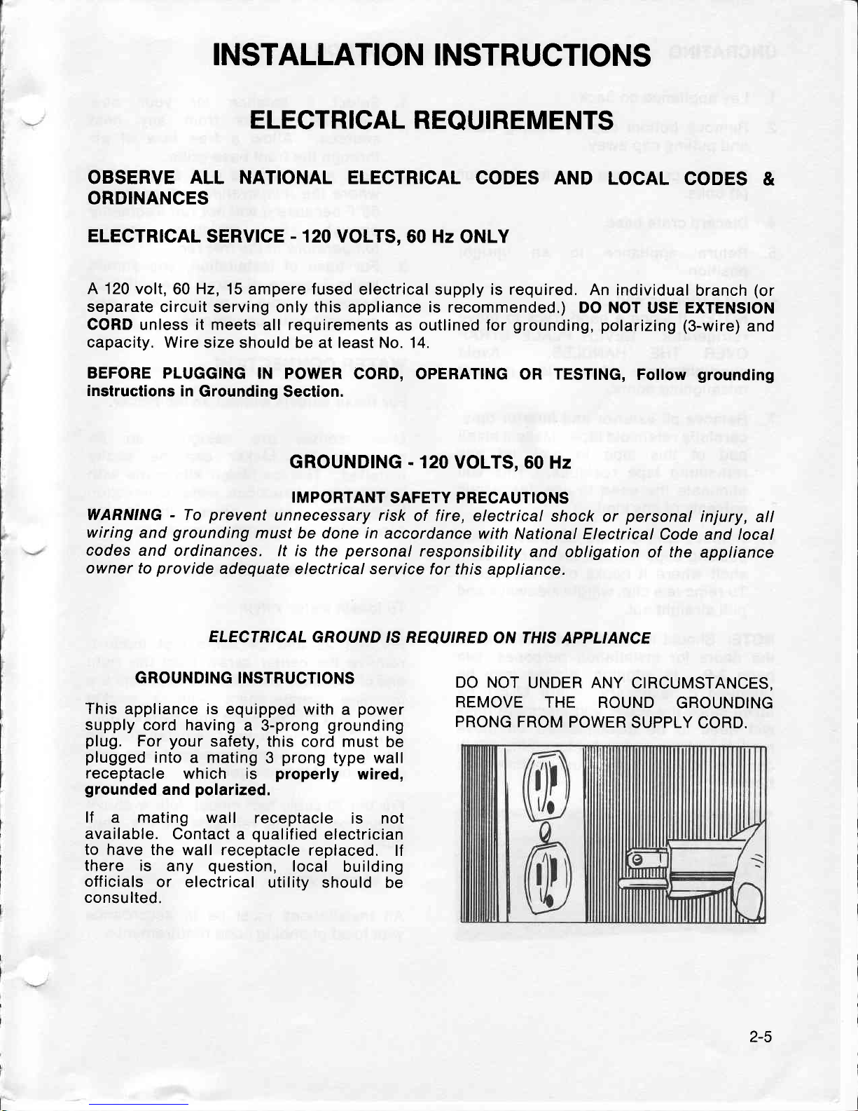
GROUNDING INSTRUCTIONS
This
appliance is
equipped with
a
power
supply
cord having
a 3-prong
grounding
plug.
For
your
safety, this cord must
be
plugged
into
a mating
3
prong
type wall
receptacle
which is
properly
wired,
grounded
and
polarized.
lf
a mating wall
receptacle
is not
available.
Contact
a
qualified
electrician
to
have the wall receptacle
replaced.
lf
there is
any
question,
local
building
off
icials
or
electrical
utility should
be
consulted.
DO NOT
UNDER ANY
CIRCUMSTANCES,
REMOVE THE
ROUND
GROUNDING
PRONG FROM
POWER
SUPPLY
CORD.
2-5
UNCRATING
1. Lay
appliance on back.
2. Remove
bottom cap
by cutting
band
and
pulling
cap
away.
3.
Remove crate base by
removing
four
(4)
bolts.
4. Discard crate base.
5. Return appliance
to an upright
position
6.
Lift carton up and off.
NOTE:
lf
using a
hand
truck to move
refrigerator.
NEVER PLACE STRAP
OVER THE
HANDLES. Avoid
overtightening strap
to
prevent
misaligning doors.
7.
Remove
all exterior and
interior tape,
carefully
retain
old
tape. Make a small
pad
of this tape
to
pick
off any
remaining tape residues. This will
eliminate
the need to use dangerous
solvents
of
any
kind.
8. Remove and discard cantilever shelf
packing
clips located
just
above each
shelf where
it hooks
onto
the frame.
To remove
a clip,
wiggle
sideways and
pull
straight out.
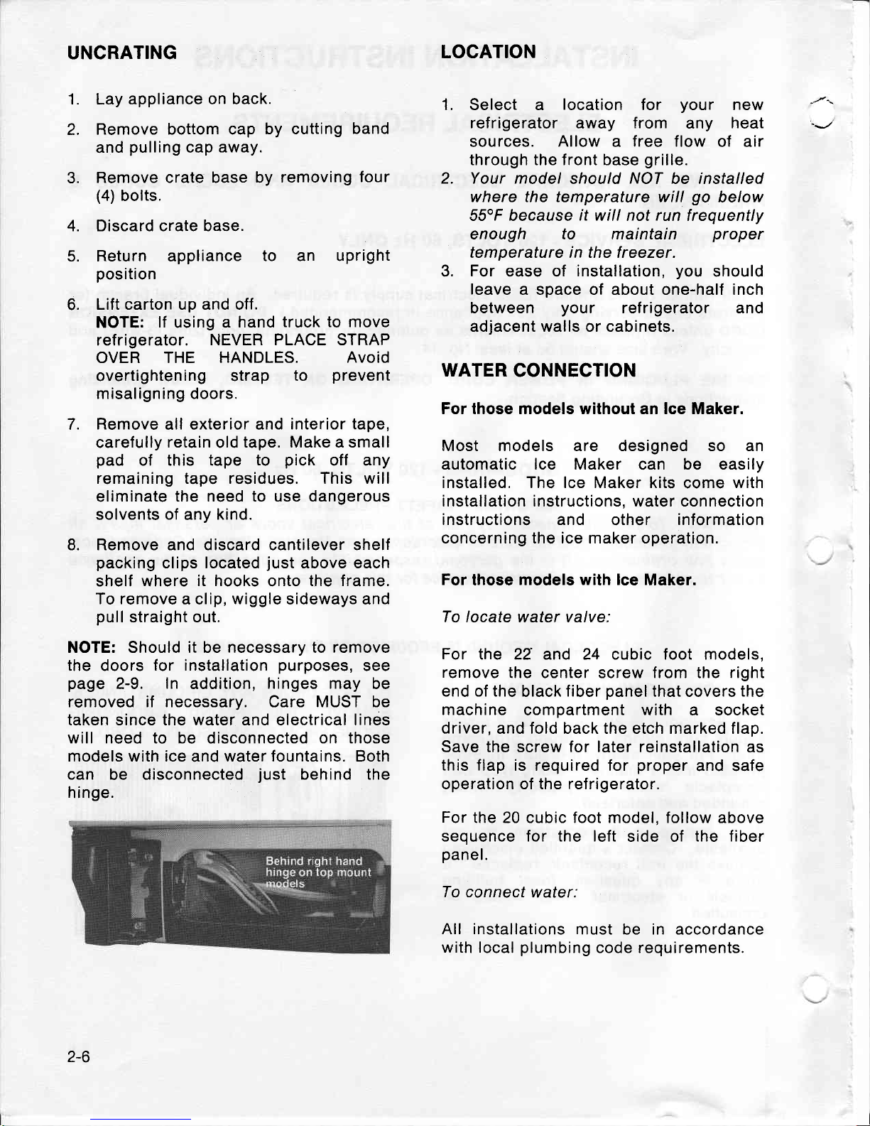
NOTE: Should it be necessary to remove
the doors
for installation
purposes,
see
page
2-9.
ln
addition,
hinges may
be
removed if necessary. Care MUST be
taken since the water and electrical lines
will
need
to be disconnected
on those
models with ice and water fountains. Both
can
be disconnected
just
behind the
hinge.
LOCATION
1. Select a
location
for
your
new
ref rigerator
away
f rom
any
heat
sources.
Allow a free
flow of air
through the front base
grille.
2. Your model
should
NOT
be installed
where the temperature will
go
below
55"F because
if
will not
run
frequently
enough to maintain
proper
temperature in the freezer.
3.
For
ease of
installation,
you
should
leave
a space of about one-half inch
between
your
ref rigerator and
adjacent walls or cabinets.
WATER
CONNECTION
For those models without an lce Maker.
Most models are designed so an
automatic lce Maker
can
be easily
installed. The lce Maker kits
come
with
installation instructions. water connection
instructions and
other
information
concerning the ice maker operation.
For
those models
with lce
Maker.
To
locate water valve:
For
the 22 and 24 cubic foot models,
remove
the center screw from the right
end of the
black
fiber
panel
that covers
the
machine
compartment with a socket
driver, and fold back the etch marked flap.
Save the screw for later reinstallation
as
this flap
is required for
proper
and safe
operation of the refrigerator.
For
the 20 cubic foot model. follow above
sequence for the left
side of
the fiber
panel.
To connect
water:
All installations
must be in accordance
with local
plumbing
code requirements.
2-6
Copper
tubing
(
114" O.D.)
and
saddle
valve can
be
purchased
f rom
local
hardware
stores.
Sweat
or
f lare
connection
can be
used
instead
of
the
compression
union,
if desired.
4.
Do
not use
plastic
tubing or
plastic
fittings
because
the connection
between
the
water supply
and
the
refrigerator
water
valve inlet
is under
constant
pressure.
Also,
certain
types of
plastic
tubing
may
become
brittle
with
age and
crack,
resulting
in water
leakage.
NOTE:
When using
unfiltered
well
water,
it is advisable
to
use
a
filter in
the water
supply
line.
This
eliminates
all
possibility
of small
particles
from entering
the water
valve.
Find
a 318" to
1" vertical COLD
water
pipe
near
the ref rigerator.
Water
pressure
must be
between
20 and
12Q
P.S.l.
Vertical
pipe
is
preferable,
but
a
horizontal
pipe
will
work.
lf
a
horizontal
pipe
is used,
install the
saddle
valve on the
top
or
the side
of
the
pipe,
not on the bottom.
Install
the saddle
valve according
to
manufacturer's
instructions
included
with the
valve.
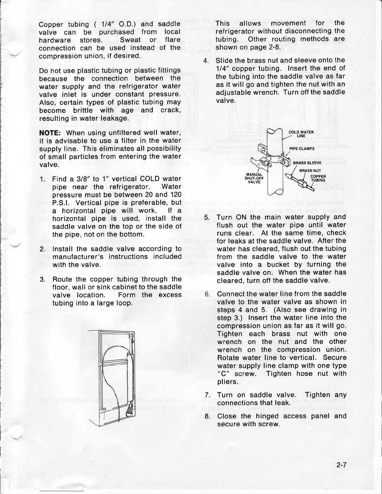
Route the copper
tubing
through
the
floor, wall or
sink cabinet
to the saddle
valve location.
Form
the excess
tubing
into a
large loop.
This allows
movement
for
the
refrigerator
without disconnecting
the
tubing.
Other
routing
methods
are
shown
on
page
2-8.
Slide
the
brass
nut and
sleeve
onto
the
114" copper
tubing.
Insert the end
of
the
tubing into
the saddle
valve as
far
as it
will
go
and
tighten
the nut with
an
adjustable
wrench.
Turn off
the saddle
valve.
COLD WATER
-
LINE
PIPE
CLAMPS
BRASS SLEEVE
1.
MANUAL
SHUT.OFF
VALVE
Turn ON
the
main water supply
and
flush
out
the
water
pipe
until
water
runs clear.
At
the same
time, check
for leaks at
the
saddle
valve, After
the
water has cleared,
flush
out
the tubing
from
the saddle
valve to
the water
valve
into a bucket
by turning
the
saddle
valve on. When
the
water has
cleared,
turn off the saddle
valve.
Connect
the water line
from the saddle
valve
to the water
valve as shown
in
steps
4 and 5.
(Also
see drawing
in
step 3.)
Insert
the water
line into the
compression union
as far as
it will
go.
Tighten each
brass
nut with one
wrench
on
the
nut
and
the other
wrench
on the compression
union.
Rotate water line
to vertical. Secure
water
supply
line clamp
with one
type
screw.
Tighten
hose nut with
pliers.
Turn
on
saddle
valve. Tighten any
connections
that
leak.
Close
the hinged access
panel
and
secure with screw.
*
/
"rorrrut
Htt**
5.
2.
3.
7.
8.
2-7
I' Plug
in
the
power
cord
and
push
the
refrigerator
to the
walt,
arranging
the
copper
tubing
so
that it
does
not
vibrate
against
the
back
of the
refrigerator
or
against
the
wall.
IMPORTANT:
Because
the
refrigerator
and ice
maker
are warm.
tt
may
take
up
to
12
hours
before
the
ice maker
produces
the
first
suppty
of ice
cubes.
^-
In
The
Crawl
Space
Under
The
Hdme
Through
The
Wall
To The
Utility
Room
Cold
Water
piDe
lf the
floor
is
not level
and
it
is
necessary
to
raise
the
rear
of the
cabinet,
we
suggest
rolling
the
rear
wheels
on
to
a
piece
of
plywood
or
other
shim
material.
Under
The
Sink
To
The
Cold
Water
pipe
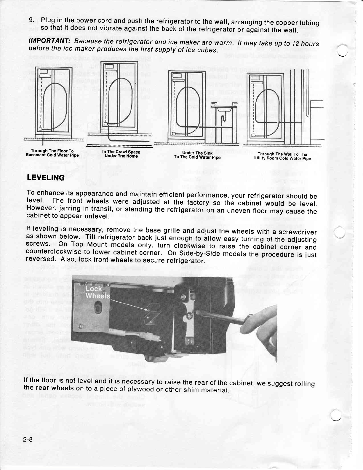
LEVELING
To
enhance
its
appearance
and
maintain
efficient
performance,
your
refrigerator
should
be
level.
The
front
wheels
were
adjusted
at
the
iactory
so
th;
cabinet
would
be levet.
Ho.wever,
jarring
in
transit,
or
standing
the
refrigerator
on
an
uneven
floor
may
cause
the
cabinet
to
appear
unlevel.
lf
leveling
is
necessary,
remove
the
base
grille
and
adjust
the
wheels
with
a
screwdriver
as
shown
below.
Tilt
refrigerator
back
jusi
enough
to
illow
easy
turning
of the
adjusting
screws.
On Top
Mount
models
only,
turn
clockwise
to
raise
the
cabinet
corner
and
counterclockwise
to
lower
cabinet
corner.
On
Side-by-Side
models
the
procedure
is
just
reversed.
Also,
lock
front
wheels
to
secure
refrigerator.
Through
The Floor
To
Basement
Cold
Water Pipe
2-8
REVERSING
DOORS
Top Mount
Models
Only
Door reversal
is NOT
possible
on
those
models that
have a built-in
ice and water
lountain.
However,
if door
removal
becomes
necessary
please
see
the note
in
Step
9.
Unplug
Refrigerator.
lf
unit
is
in
use,
remove food
from fresh
food compartment
and
freezer com
partment.
Removing doors.
NOTE:
Taping doors shut
prior
to
physically
removing them
may
prevent
unnecessary
damage.
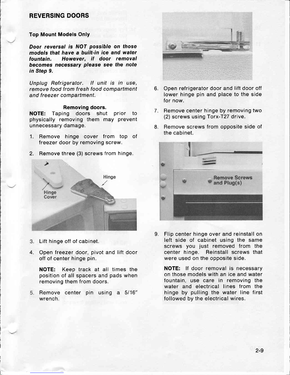
1. Remove hinge cover
from top of
treezer door by
removing screw.
2. Remove
three
(3)
screws
from hinge.
&
Lift
hinge
off of cabinet.
Open
freezer
door,
pivot
and
lift door
off of center
hinge
pin.
NOTE: Keep track at all
times the
position
of all spacers and
pads
when
removing them from doors.
Remove
center
pin
using
a 5116"
wrench.
Open
refrigerator door and
lift
door off
lower hinge
pin
and
place
to the side
for now.
Remove center
hinge by
removing
two
(2)
screws
using Torx-T27 drive.
Remove screws
from opposite side
of
the cabinet.
Flip
center
hinge
over
and reinstall on
left
side
of cabinet using
the
same
screws
you
just
removed from the
center
hinge. Reinstall screws that
were used on
the
opposite
side.
NOTE: lf door
removal is necessary
on those models with an ice and
water
fountain,
use
care in removing the
water
and
electrical lines
from the
hinge by
pulling
the water line
first
followed by
the
electrical
wires,
6.
L
7.
9.
4.
2-9
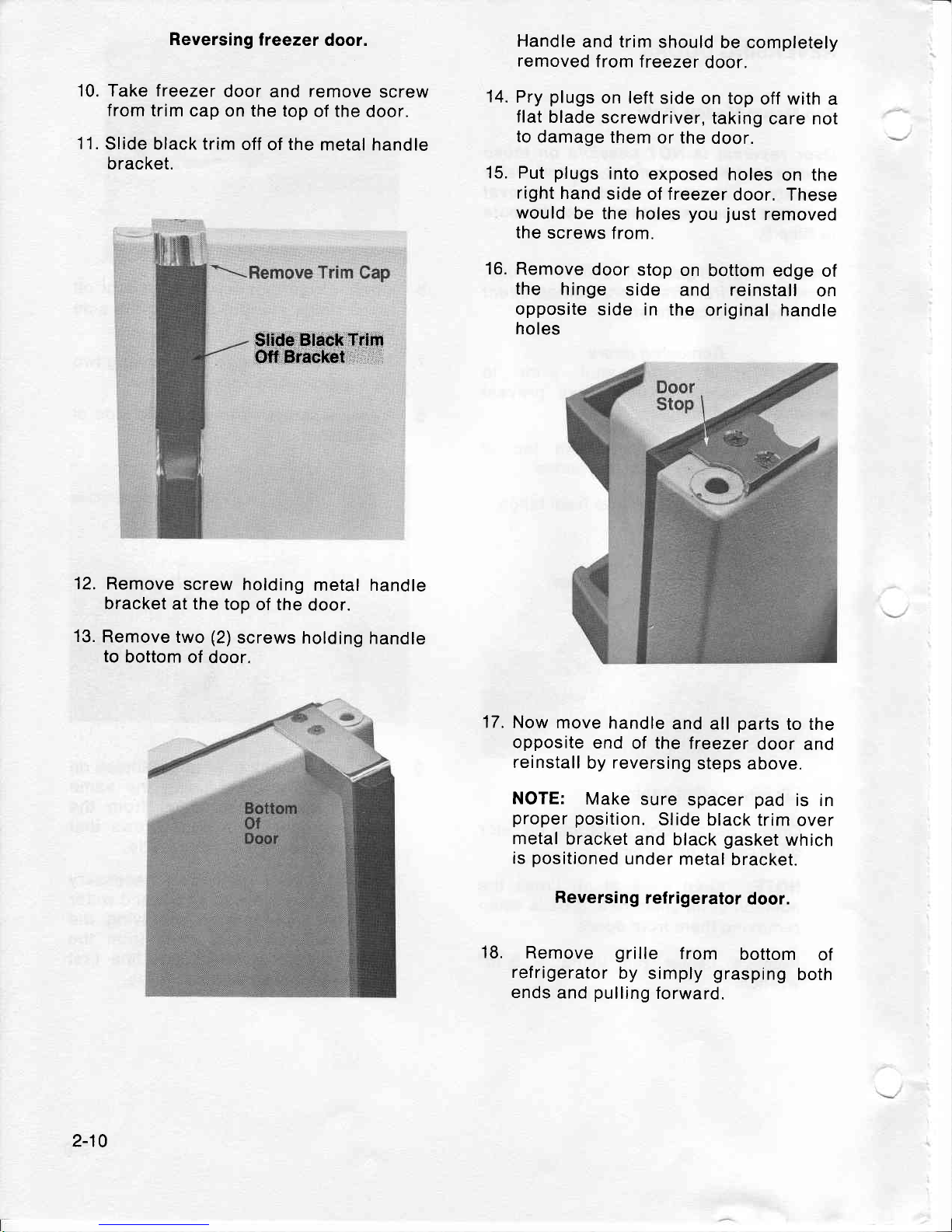
Reversing
lreezer
door.
10. Take freezer
door
and
remove
screw
from
trim cap
on the top
of the
door.
11.
Slide black trim
off
of
the
metal handle
bracket.
$tide Black
Trim
Off
Bracket
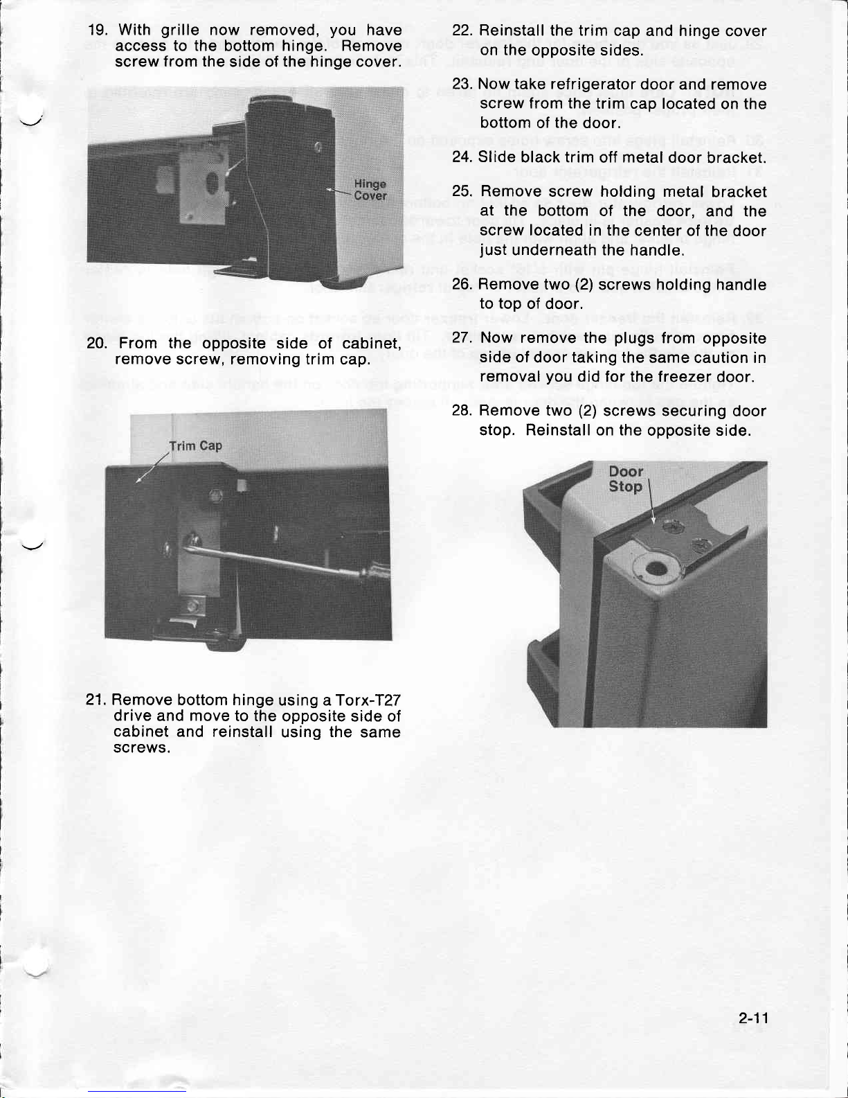
12.
Remove
screw
holding
metal handle
bracket
at
the
top
of the
door.
13.
Remove
two
(2)
screws holding
handle
to
bottom
of door.
Handle
and trim
should
be completely
removed
from freezer
door.
Pry
plugs
on left
side
on top
off with
a
flat
blade
screwdriver,
taking
care not
to
damage
them
or the
door.
Put
plugs
into
exposed
holes
on the
right
hand
side of treezer
door. These
would
be the
holes
you
just
removed
the
screws
from.
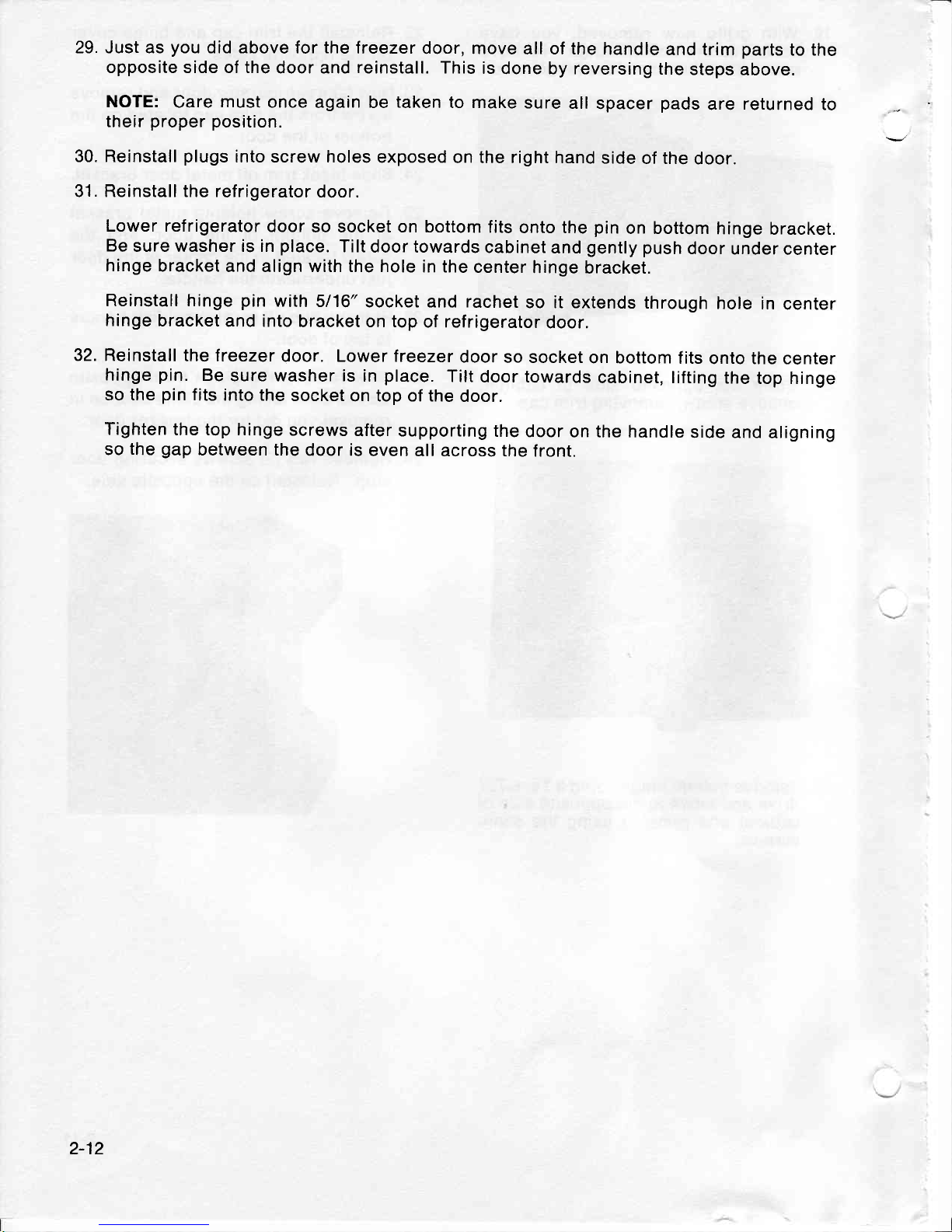
Remove
door
stop
on
bottom edge
of
the
hinge
side
and reinstall
on
opposite
side in
the
original handle
holes
Now
move
handle
and all
parts
to the
opposite
end
of the freezer
door
and
reinstall
by
reversing
steps
above.
NOTE:
Make
sure
spacer
pad
is in
proper position.
Slide black
trim
over
metal
bracket
and black
gasket
which
is
positioned
under
metal
bracket.
Reversing
refrigerator
door.
Remove
grille
f rom
bottom
of
refrigerator
by simply
grasping
both
ends
and
pulling
forward.
14.
15.
16.
17.
18.
2-10
19. With
grille
now removed,
you
have
access to the
bottom
hinge. Remove
screw
from the
side of the hinge cover.
20. From the
opposite side of cabinet,
remove
screw, removing trim
cap.
21. Remove
bottom hinge
using aTorx-T?7
drive
and move to the
opposite side of
cabinet and reinstall
using
the
same
screws.
22. Reinstall
the trim
cap and hinge
cover
on the
opposite sides.
23. Now take refrigerator
door and remove
screw from the
trim cap located
on the
bottom
of
the
door,
24. Slide
black trim
off
metal
door
bracket.
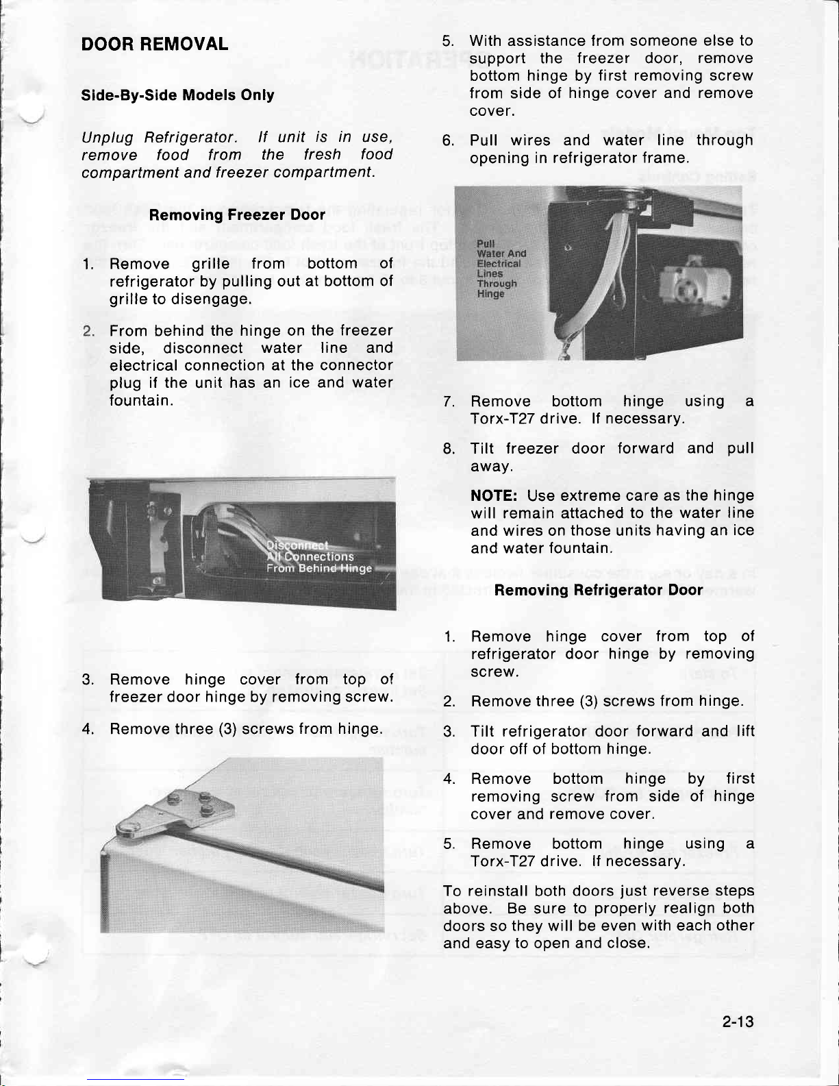
25.
Remove
screw holding metal
bracket
at
the
bottom
of the door,
and the
screw located in the
center of the
door
just
underneath the
handle.
26. Remove
two
(2)
screws holding handle
to top
of door.
Now remove the
plugs
from
opposite
side of
door
taking
the
same caution in
removal
you
did for the treezer
door.
Remove
two
(2)
screws securing
door
stop. Reinstall on the
opposite side.
27.
28.
2-11
29. Just as
you
did above for the
treezer
door, move
all of the
handle
and trim
parts
to the
opposite side of the
door and
reinstall.
This
is
done by reversing
the
steps
above.
NOTE:
Care
must
once
again be
taken
to make
sure
all
spacer
pads
are
returned
to
their
proper position.
30. Reinstall
plugs
into
screw
holes
exposed
on the right
hand
side
of the
door.
31. Reinstall the refrigerator
door.
Lower refrigerator
door
so socket on bottom
fits
onto the
pin
on bottom
hinge
bracket.
Be
sure washer is in
place.
Tilt
door towards
cabinet
and
gently
push
door
under
center
hinge
bracket
and align with the hole
in the
center
hinge
bracket.
Reinstall hinge
pin
with
5116"
socket and rachet
so it extends
through
hole
in
center
hinge
bracket
and into
bracket on top
of refrigerator
door.
32. Reinstall
the freezer
door. Lower treezer
door
so socket
on bottom
f its
onto the center
hinge
pin.
Be
sure washer is
in
place.
Tilt
door towards
cabinet, lifting
the
top hinge
so the
pin
fits
into the
socket
on top of the
door.
Tighten
the top hinge
screws
after supporting
the
door
on the handle
side and
aligning
so
the
gap
between the
door is
even
all across the
front.
2-12
1.
DOOR REMOVAL
Side-By-Side
Models
Only
Unplug
Refrigerator.
lf unit
is in
use,
remove
food from
the f resh
food
com
partment
and
f reezer compartment.
Removing
Freezer Door
Remove
grille
from bottom
of
refrigerator by
pulling
out at bottom
of
grille
to disengage.
From behind
the hinge on
the treezer
side, disconnect
water line and
electrical
connection
at the connector
plug
if the
unit
has an
ice
and
water
fountain.
Remove hinge cover
f rom top of
lreezer door hinge by removing screw.
Remove three
(3)
screws
from hinge.
With assistance from someone else
to
support
the treezer door,
remove
bottom hinge by
first removing screw
from side of
hinge
cover
and remove
cover.
Pull
wires
and
water line through
opening
in refrigerator
frame.
7. Remove bottom
hinge using a
Torx-I27 drive.
lf necessary.
Tilt
lreezer door forward
and
pull
away.
NOTE:
Use
extreme care as
the hinge
will remain attached
to the water line
and wires on
those
units
having an
ice
and water fountain.
Removing Refrigerator
Door
1. Remove hinge
cover f rom
top
of
refrigerator door
hinge by removing
screw.
Remove
three
(3)
screws
from
hinge.
Tilt refrigerator door
forward
and
lift
door off of
bottom hinge.
Remove bottom hinge by
f irst
removing
screw
from side of hinge
cover and remove cover.
Remove bottom
hinge using a
Torx-f27 drive.
lf necessary.
To reinstall
both
doors
just
reverse steps
above. Be sure
to
properly
realign both
doors so
they will be even
with
each
other
and easy
to
open and
close.
6.
4.
5.
8.
3.
4.
2.
3.
2-13
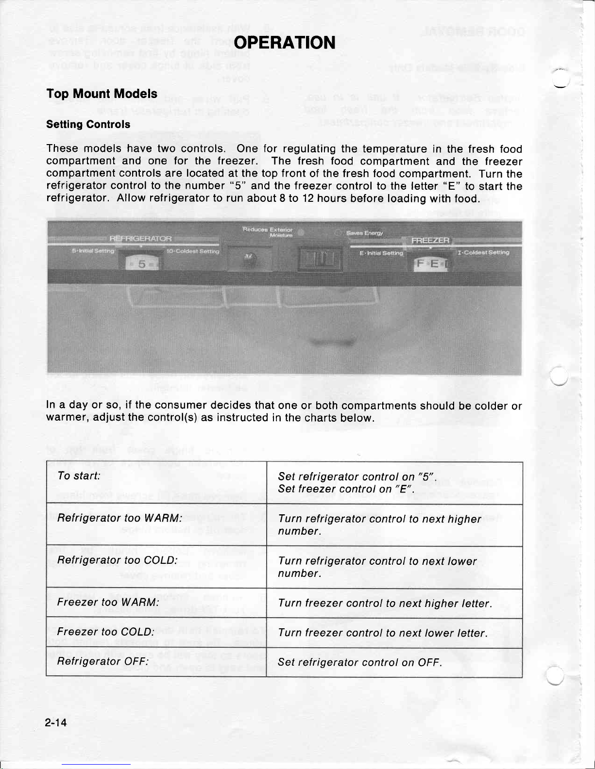
OPERATION
Top Mount Models
Setting Controls
These
models have two
controls. One
for
regulating the
temperature in
the fresh
food
compartment and one for the
freezer. The fresh food
compartment
and the treezer
compartment controls
are
located
at the top front
of the fresh food
compartment.
Turn the
refrigerator control to the number
"5"
and
the
freezer control to the
letter
"E"
to start the
refrigerator. Allow refrigerator
to run
about 8 to 12 hours
before loading
with food.
In
a day
or so, if the consumer
decides that
one
or both compartments
should
be colder or
warmer,
adjust the control(s)
as instructed
in the
charts
below.
To
start:
Set refrigerator
control
on
"5"
Set
freezer
control
on
"E".
Refrigerator
too WARM:
Turn
refrigerator
control to next
higher
number.
Refrigerator
too
COLD:
Turn
refrigerator
control to
next lower
number.
Freezer
too
WARM:
Turn
freezer control
to next higher
letter.
Freezer
too
COLD:
Turn
freezer control
to next
lower letter.
Refrigerator
OFF:
Set ref
rigerator control
on
OFF.
2-14
USE OF CONTROLS
f
MPORTANT: Except when
starting, do
not
change
either control more
than one number
at
a
time. ALLOW 24
HOURS FOR TEMPERATURE
TO
STABILIZE BEFORE RESETNNG.
Changing either control will have
some effect on the temperature
of the other
compartment.
The number
"9"
lreezer control
setting
is recommended
for
short term
use ONLY.
Please note:
The refrigerator may run for
several
hours
when first
started
up. This is
normal
and shouldn't
be cause for alarm.
Warm
Cabinet Surfaces
At
times, the front
surfaces of the refrigerator
cabinet
may be warm
to the touch.
This is a
normal function
of the refrigerator,
This feature
prevents
moisture
from
condensing
on
the
outside of the refrigerator
during
humid
weather.
This condition
may
be
noticeable
when
you
first
start the refrigerator,
during
hot weather,
and excessive
or
lenghty
door openings.
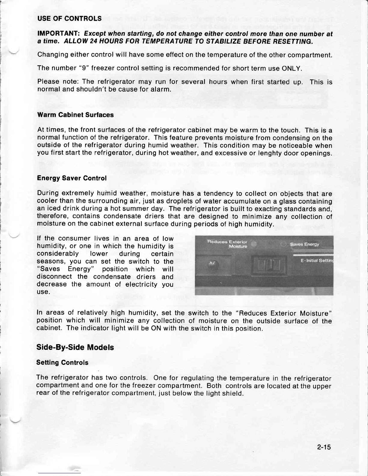
Energy
Saver
Control
During
extremely
huinid weather,
moisture
has a tendency
to collect
on objects that
are
cooler than the
surrounding
air,
just
as droplets
of water accumulate
on
a
glass
containing
an iced drink
during a hot
summer day.
The refrigerator
is
built
to
exacting
standards and,
therefore,
contains
condensate
driers
that
are designed to
minimize
any collection
of
moisture
on
the
cabinet
external surface
during
periods
of high
humidity.
lf the
consumer lives
in
an area of low
humidity, or
one in which
the humidity
is
considerably lower
during certain
seasons,
you
can
set the switch
to the
"Saves
Energy"
position
which
will
disconnect the
condensate
driers
and
decrease the
amount
of electricity
you
use.
In
areas of relatively
high humidity,
set the
switch to the
"Reduces
Exterior
Moisture"
position
which
will
minimize
any collection
of moisture
on
the
outside
surface
of the
cabinet.
The indicator
light will
be ON with
the
switch
in
this
position.
Side-By-Side
Models
Setting
Controls
The
refrigerator
has two
controls.
One for regulating
the temperature
in
the refrigerator
compartment
and
one for the freezer
compartment.
Both controls
are located
at the
upper
rear
of
the
refrigerator
compartment,
just
below the light
shield.
2-15
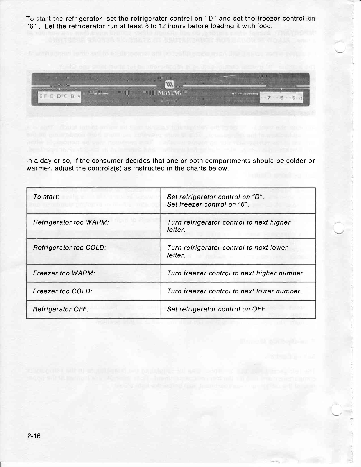
To
start
the refrigerator,
"6"
. Let
the
relfrigerator
set
the refrigerator
run at least 8
to 12
control on
"D"
and
set
the
hours before loading it with
freezer control
food.
ln a day or so, if the consumer
warmer,
adjust
the
controls(s)
decides
that one
or both compartments should be colder
or
as
instructed in
the charts below,
To
start: Set refrigerator control
on
"D".
Set f reezer control
on
"6".
Refrigerator too WARM:
Turn refrigerator control
to
next higher
letter.
Refrigerator too
COLD:
Turn refrigerator control to next lower
letter.
Freezer
too WARM:
Turn
freezer
control to
next
higher number.
Freezer too
COLD.
Turn freezer control to next lower number.
Refrigerator
OFF:
Set refrigerator
control
on OFF.
2-16
USE
OF CONTROLS
IMPORTANT:
Except when
starting, DO NOT
change either
control more than
one letter
or
one number
at a time. Allow 24
hours tor temperature
to
stabilize betore resetting.
To turn
off
the
refrigerator,
set the refrigerator
control
on OFF.
Warm
Cabinet Surfaces
At times,
the front
surfaces of the refrigerator
cabinet may
be
warm
to the touch.
This is
a
normal
function
of
the
refrigerator. This
feature
prevents
moisture from
condensing
on the
outside
of
the refrigerator
during
humid
weather.
This condition
may
be
noticeable
when
you
first start the
refrigerator,
during hot weather,
and excessive
or lengthy
door openings.
2-17

-l
MITYTAG
SECTION 3
SERVICE
PROCEDURES
GENERAL INFORMATION
TOP MOUNT
MODELS
FORCED AIR
SYSTEMS
On all forced air models,
an air circulating fan
draws cold
air
from
around the evaporator
and directs it
to
the fresh food
and treezer
compartments. A
carefully measured amount
of
chilled
air
is
directed into the fresh food
compartment
through a
baffle
to
maintain the de-
sired fresh food
compartment temperature.
The
greater
part
of chilled air is directed into
the freezer
compartment to maintain
freezer temperature.
Forced
air models use a fan
cooled
condenser. The
evaporator
is
automatically
defrosted
every six or eight hours
of
compressor run time
depending
on
the
model. Defrosting
is
accomplished by
a defrost
heater
activated by a timer.
The
accumulated moisture is
drained into
a defrost
pan
located
in the compressor
area of the
cabinet.
REFRIGERATION
CYCLE
@l
HEATEXCHANGER
-
---
-
cAptLLARy
I
ols - rrex
pREssuRE
ffi
rrouro-xrot
pREssuRE
CONDE NSER
3-1
EVAPORATION
OF
ICE
CUBES
(rop
Mount
& side-By-side
Moders)
Since
ice
cubes have a moisture
vapor
pressure
above them,
the vapor
is
constantly
being
picked
up
in the
dry air stream
and deposited
on
the
evaporator.
This
physical
change
known
as
"sublimation",
is the
changing
of a solid to
a vapor
without
going
through liquid
state. In a forced
air treezer
compartment,
this
action will
be readily
noticed
by a customer
who
does
not
use ice cubes
with regularity.
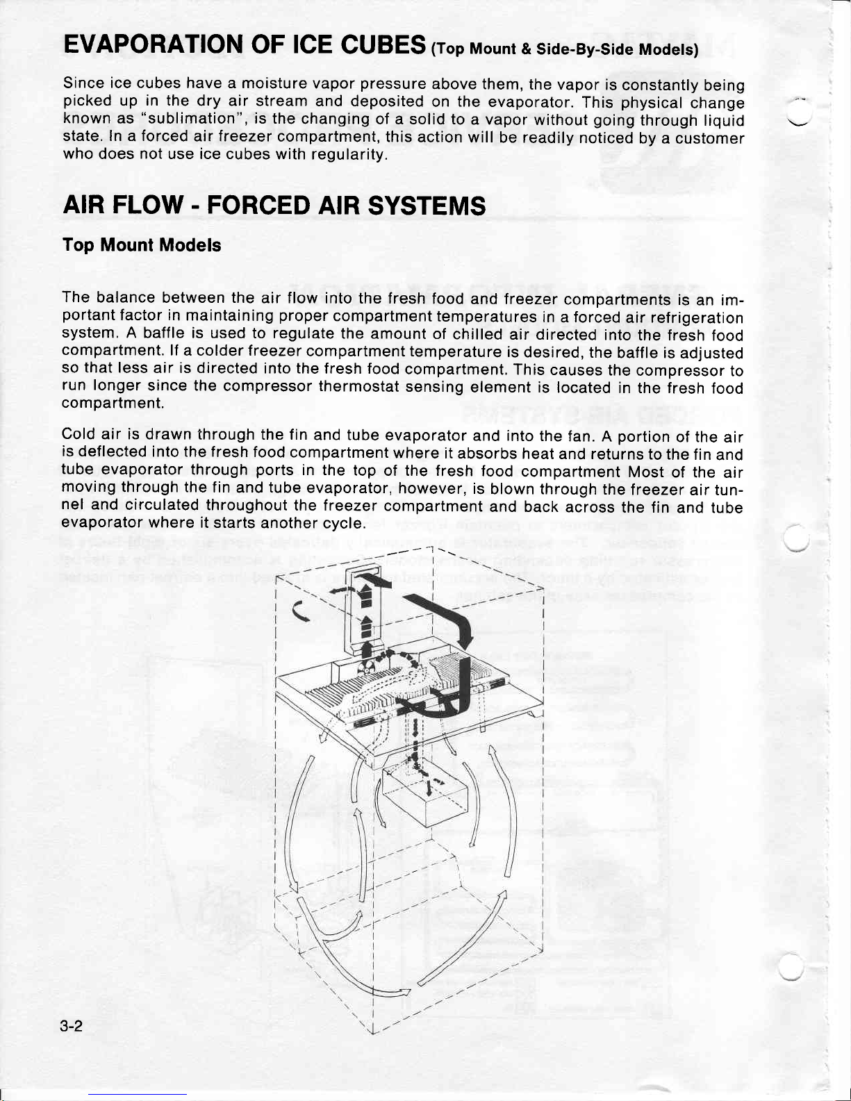
AIR
FLOW. FORCED
AIR
SYSTEMS
Top
Mount Models
The
balance
between the
air flow
into the fresh
food
and Ireezer
compartments
is
an im-
portant
factor in
maintaining
proper
compartment
temperatures
in a forced
air
refrigeration
system.
A
baffle is used
to regulate
the
amount of
chilled
air directed
into
the fresh
food
compartment.
lf
a colder treezer
compartment temperature
is
desired,
the
baffle is
adjusted
so that less
air is directed
into the
fresh food
compartment.
This
causes
the
compressor
to
run longer
since the
compressor thermostat
sensing
element is
located
in the fresh
food
compartment.
Cold
air is
drawn through
the fin
and tube
evaporator
and
into
the
fan.
A
portion
of the
air
is
deflected
into the f
resh food
compartment
where
it
absorbs heat
and returns
to the
f in
and
tube
evaporator
through
ports
in the
top
of the fresh
food
compartment
Most
of the
air
moving
through the
fin
and tube
evaporator,
however,
is
blown through
the
freezer
air tun-
nel
and
circulated
throughout
the freezer
compartment
and back
across
the fin
and tube
evaporator
where
it starts
another
cycle.
-r'
-
-l
\\
3-2
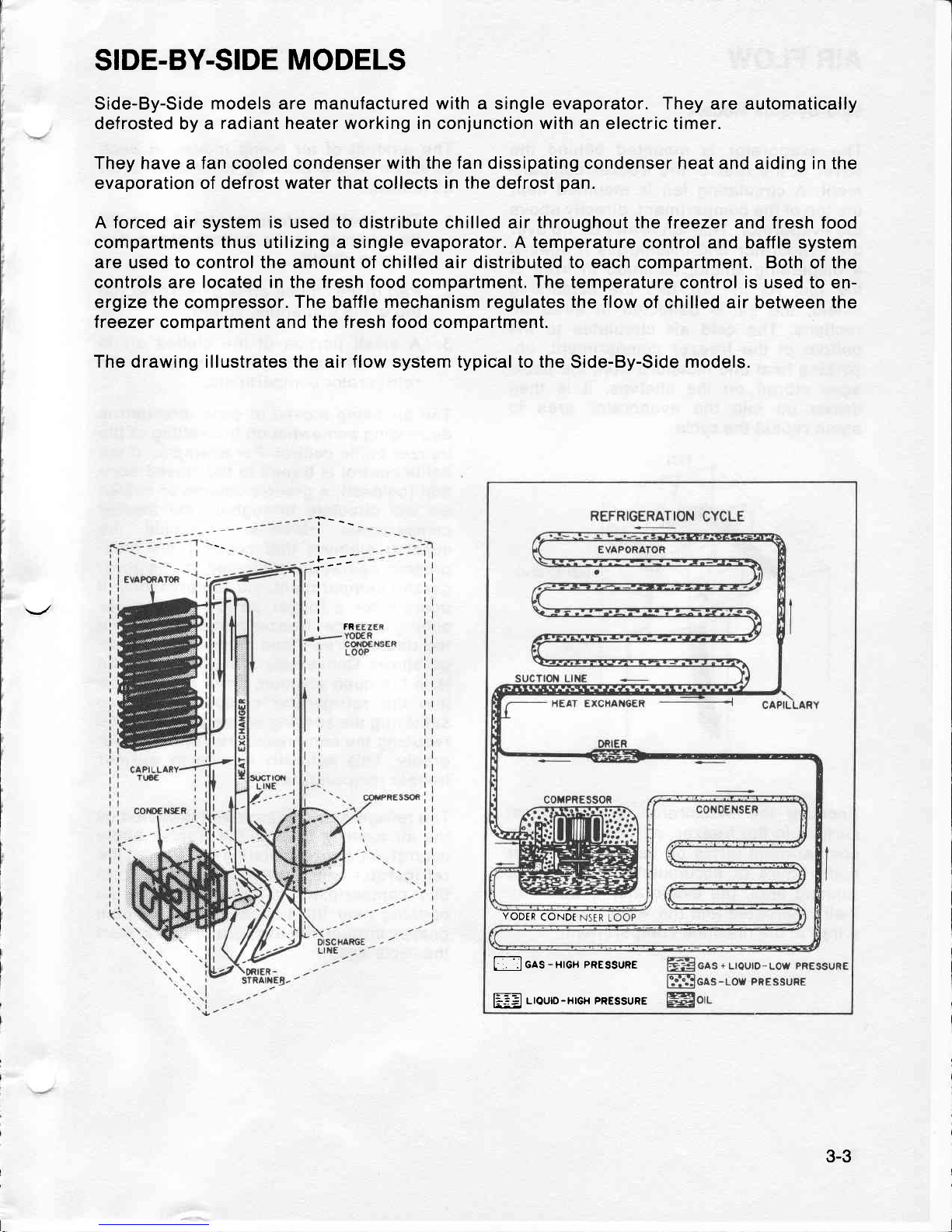
SIDE-BY-SIDE
MODELS
Side-By-Side
models
are
manufactured with a single evaporator.
They are automatically
defrosted by a
radiant heater working in conjunction with an
electric
timer.
They have a fan cooled condenser
with the fan
dissipating condenser heat and aiding in the
evaporation of defrost water that collects in
the
defrost
pan.
A forced
air system
is
used
to distribute
chilled air
throughout the
lreezer and fresh food
compartments
thus
utilizing a single evaporator. A
temperature
control and baffle
system
are
used
to
control
the amount of chilled air distributed to
each compartment, Both of the
controls are
located in the fresh food compartment. The temperature
control is used to en-
ergize
the
compressor.
The
baffle
mechanism regulates the flow
of chilled air
between
the
freezer compartment
and
the fresh food compartment.
The drawing illustrates the air flow system typical to the
Side-By-Side
models.
"i----
I
I
L--'
1"-'
I
I
I
I
rFR
L
:.
:IGAS-HIGH
PRESSURE
liiEJ
L|OUD-H|GH PRESSURE
YODER
CONDT
3-3
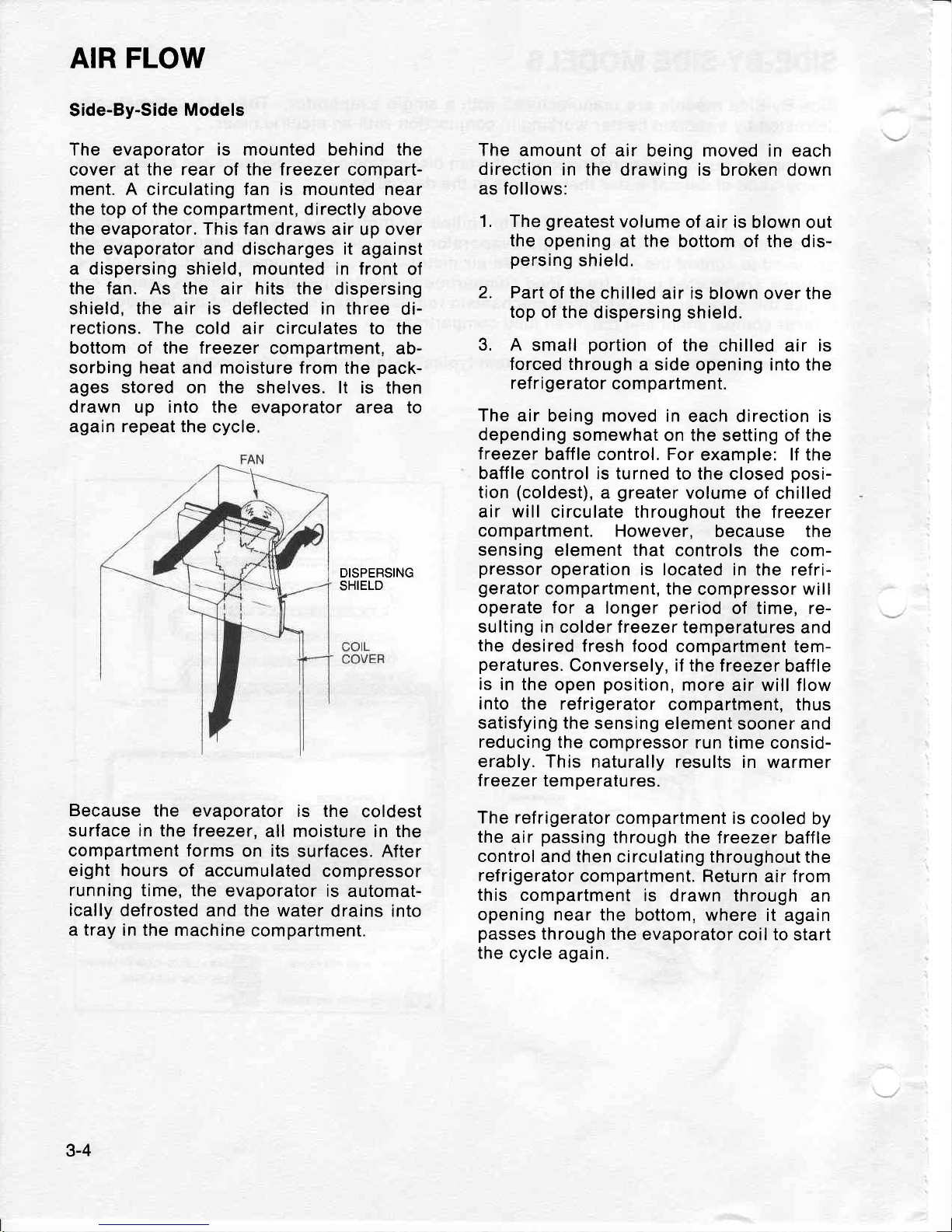
AIR
FLOW
Side-By-Side
Models
The evaporator is mounted behind the
cover at
the rear
of
the freezer
compart-
ment. A circulating fan is mounted near
the top of the compartment, directly
above
the
evaporator. This fan
draws air up over
the evaporator and discharges it
against
a dispersing shield, mounted in front
of
the fan. As the
air hits the dispersing
shield, the air is deflected in three
di-
rections. The
cold air circulates to the
bottom of the freezer
compartment,
ab-
sorbing heat and moisture from
the
pack-
ages
stored on the shelves. lt is
then
drawn up into the
evaporator atea to
again
repeat the
cycle,
DISPERSING
SHIELD
Because
the evaporator
is the
coldest
surface in the
treezer,
all moisture in the
compartment forms
on
its
surfaces.
After
eight hours
of
accumulated
compressor
running
time, the
evaporator
is automat-
ically
defrosted
and the water
drains into
a
tray
in the machine
compartment.
The
amount
of air being moved in each
direction
in
the drawing is broken
down
as follows:
1. The
greatest
volume
of air is
blown out
the
opening
at the bottom of the
dis-
persing
shielc.
2.
Part
of
the
chilled air is
blown over the
top
of
the
dispersing
shield.
3. A
small
portion
of the chilled
air
is
forced through
a side
opening into the
ref ri
gerator
com
partment.
The
air being moved in
each direction is
depending
somewhat
on the setting of the
treezer
baffle control, For
example: lf the
baffle control is turned
to the
closed
posi-
tion
(coldest), a greater
volume
of chilled
air
will
circulate throughout
the treezer
compartment.
However,
because the
sensing
element
that
controls the
com-
pressor
operation is located
in the refri-
gerator
compartment, the
compressor will
operate for
a longer
period
of time, re-
sulting in colder lreezer
temperatures
and
the
desired fresh food
compartment tem-
peratures.
Conversely, if the
treezer
baffle
is
in the
open
position,
more
air will flow
into
the refrigerator
compartment,
thus
satisfyinQ the
sensing
element sooner
and
reducing
the compressor
run time consid-
erably.
This naturally
results in warmer
freezer temperatures.
The refrigerator
compartment is
cooled by
the
air
passing
through
the freezer
baffle
control
and then circulating throughout
the
refrigerator
compartment. Return
air from
this compartment
is drawn
through an
opening near
the bottom, where
it again
passes
through the
evaporator coil to
start
the
cycle again.
3-4
I-.l
CHECKING
OPERATIOT\f
-
(A'
Moders)
The
following
general
information
ex-
plains
several
method for
checking oper-
ation of the refrigeration
system. This
information
applies to all systems
covered
in
this manual.
The
correct operation
of a refrigeration
system is
dependent upon the
proper
functioning
of each of the
parts
comprising
the system. lf the
system does
not operate
properly
(long
run
periods,
warmer than
normal
temperatures),
the trouble
may be
caused
by one of the following
conditions.
RESTRICTED
CAPILLARY
TUBE
The
opening
of a capillary
tube is
about
the
same
diameter as the
period
at the
end of this
sentence. This
should indicate
that
it doesn't
take much
to restrict
this
tube. lt
should also tell
you
to
use care
when
any service
procedures
involve
moving
or
touching
the
capillary
tube. A
very
slight
kink
can
cause
a complete re-
striction
of
the tube.
Restrictions
of the
capillary tube
may be
caused
by:
(1)
moisture
freeze-up,
(2)
tor-
eign
particles
lodged
in the tube,
or
(3)
a
bend
or
kink.
lf the
capillary tube
is restricted,
there
will
be a noticeable
lack of frost
on
all of the
cooling
surfaces; the
compressor
may
op-
erate for
a short
period
of time
and then
cycle
on the
overload. Because
some mo-
dels can hold the
entire
charge in
the
condenser,
the compressor
may run con-
tinuously
and
definite
vacuum
will be no-
ticed
in the low
side.
When moisture
freeze-up
causes
a restriction,
it usually
occurs
at the
outlet
end of the
capillary
tube.
Normally,
a frost
build-up
can
be
detected in
this
area,
but
insulation
wrapped
around the
tubing may
conceal
or limit the
amount
of frost
accumulation.
Expose
the discharge
end of the capillary
and apply heat
at this
point.
lf there
is
enough head
pressure,
and if the
re-
striction
is caused
by moisture
freeze-up,
you
will
be able to
hear a
gurgling
noise
as the
heat releases
the ref
rigerant
through the
tubing.
It is
possible
that this
moisture will
be ab-
sorbed
by the
drier and remedy the
trou-
ble. However, if the
freeze-up recurs,
you
must replace
the drier.
A kink in
the capillary
tube will reveal
about the
same symptom
as a moisture
freeze-up
except for the
accumulation
of
frost.
Check the
entire length
of
the
capil-
lary
tube and, if
possible,
straighten the
kink to
relieve the
restrictions.
Check the
unit operation to
see if
you
have helped
the
situation. lf the trouble
persists,
re-
place
the
defective
part.
lf
the freeze-up
condition
does not
exist
and
there
is
not a kink,
you
can
assume
that
a foreign
particle
is
causing the re-
strictions
--
the
only remedy
in this
case
is
to replace
the restricted
part.
PARTIAL
RESTRICTION
IN LOW
SIDE
TUBING
Bent tubing,
foreign
matter,
or moisture in
the
system may
cause
a
partial
restriction
in
the low
side tubing. This
is usually
in-
dicated
by
frost-free
tubing
between the
restriction
and the
capillary
tube
and by
f rost-covered
tubing
between
the re-
striction
and
the
suction line.
The
re-
striction
acts like
a second
capillary tube,
increasing
the
pressure
ahead
of
it
(warming)
and
decreasing the
pressure
beyond it
(cooling).
To confirm
the
exist-
ence
of a restriction
in the low
side tubing,
perform
operational
pressure
checks.
3-5
SLOW
LEAK IN
SYSTEM
On forced air
models, long run time will
be
noticed during the
early
stages of a
leak. As the refrigerant
continues
to es-
cape, both compartments
will
gradually
warm up and the compressor will run
continuously.
The freezer will
probably
warm
up
first.
INCORRECT REFRIGERANT
CHARGE
The
sealed unit
may
have too much refri-
gerant
(overcharged
system) or too little
refrigerant
(undercharged
system). The
following
paragraphs
will inform
you
on
how to recognize
a
system
with these
de-
fects.
An
overcharged system may
have a frost
back condition
appearing outside the
in-
sulation
sleeve on the
suction line
at
the
cabinet
rear.
When the
compressor
stops,
the frost
melts
and drips on the floor.
A
heat
exchanger
separation will
also cause
this
symptom.
An
undercharged
system depending
on
the
degree
of undercharge,
will
operate
with temperatures
above normal
and the
compressor
run time
will be increased.
The
greater
the
undercharge,
the higher
the temperature
will
be
and
the longer
the
run
time.
An
undercharged
system must
be
purged,
evacuated,
and recharged
with the
proper
amount
of refrigerant.
Before recharging,
however,
test for
refrigerant leaks.
DEFECTIVE
COMPRESSOR
A
compressor which is not
pumping
ade-
quately
will not
cool effectively.
All cool-
ing
surfaces
may be covered
with a thin
film
of
frost,
but the
temperature will
not
descend to the
cut-out temperature
of the
control, even
with continuous
running
of
the
compressor.
Because these
symptoms
are similar to
a
refrigerant leak, it
is
advisable to thor-
oughly leak
test
at
this
point.
lf no leak
is
indicated,
install
gauges
and check the
operating
pressures.
lf the
high side
pres-
sures are lower
than those
specified,
and
low side
pressures
are higher than
speci-
fied,
suspicions of
an inefficient
compres-
sor will
be confirmed
and the compressor
must be replaced.
PRESSURE
UNLOADING IN
SYSTEM
The
compressor may
stall
and cycle on
the
overload
protector
if
an attempt is
made
to restart the
unit immediately
after
it has
stopped. This
is
because
the refri-
gerant
pressure
is
high
on the condenser
side and low on the
evaporator
side. When
the
compressor
stops running, the liquid
slowly
passes
through
the capillary tube
and the
pressures
are said to be
"unload-
ing". Pressure
unloading in the system
may
take from 3 to
6 minutes.
PULL
DOWN
OVERLOAD
lf the
cabinet
compartments
are
warm
when
the
compressor starts, the
"pull
down" may
temporarily
overheat the
compressor
and cause
cycling on the ov-
erload
protector.
3-6
LEAK TESTING
The
following
general
information
ex-
plains
several methods
of checking the
refrigeration
system
for
leaks. This infor-
mation
applies to
all systems covered in
this
manual.
lf there
is an undercharge
of
refrigerant
and the system has
not
been recently
opened, there is
probably
a leak in the
system. In that
case, it would
be only a
temporary
solution to
add
ref
rigerant
without
first locating
and repairing
the
leak
since
adding refrigerant
will not
per-
manently
correct the
difficulty.
The leak
must
be
located
and repaired
if
possible,
after which
the
entire system must
be
re-
charged
with the
proper
amount of refri-
gerant.
Whenever
a new
charge
of
refrigerant
is
added, it is
necessary
to in-
stall a new
drier.
Any
leak, regardless
of its
size, must
be
located
before
you
can
determine the
op-
erative
status
of the
system
components.
Do
not replace
a
component
because the
system is
short
of refrigerant
unless
a
non-repairable
leak
is found.
lf
your
analysis
indicates
a leak, find
it
before
opening the
system.
You
are more
likely
to
pinpoint
the
leak
before
dis-
charging
than if the
surrounding
air is
contaminated
with ref
rigerant
f rom
a
newly
opened
system.
The
presence
of oil
around a tubing
joint
usually indicates
a leak,
but don't let this
be the determining
factor.
Always
check
the area with
a
leak
detector
to make
sure.
To simplify leak
detection, keep
the sys-
tem
pressurized
to
a minimum
of 75 P.S.l.
This is
easily
accomplished
for high
side
testing
by merely running
the
compressor.
To
pressurize
the low
side,
allow the en-
tire
system to
warm
up to room temper-
ature.
Often
enough
refrigerant
may have
es-
caped to make it
impossible
to raise
the
pressure
enough to leak
test effectively.
In
cases of this
nature,
clamp a
piercing
valve to the
compressor
process
tube and
add enough refrigerant
to conduct the
test.
Leak
testing with
a Halide
torch is consid-
ered
satisfactory in
most
cases, but for
more
accurate testing,
we recommend
the
use
of a Dielectric
Differential Leak
De-
tector.
This
transistorized
model reduces
the
guesswork
in leak
testing
because it is
more
sensitive,
faster responding,
and
capable
of detecting a leak
even
though
the
surrounding
air is
contaminated.
The
leak
gun provides
an audible indication
of
a
refrigerant
leak.
3-7
LEAK
TESTING
YODER
LOOP
The
following
general
information
ex-
plains
several
methods
used
in leak
test-
ing the
yoder
loop.
The
yoder
loop is
routed
in the front
cabi-
net
flange at
the top and
sides.
The
yoder
condenser
loop warms
the front
of
the ca-
binet
and
thus
reduces
the formation
of
condensation
on
the cabinet
front.
By
transferring
heat
to the cabinet
front, the
loop helps cool
the condensing
system.
Since
the
yoder
condenser
loop cannot
be
reached
for leak
testing, it
is impossible
to
check
in the normal
manner.
Instead,
it
must be
disconnected
from
the system
and
checked
separately.
NOTE: BE SURE
A LEAK IS
NOT PRESENT
IN ANY EXTERNAL
TUBING OR
JOINT
BE-
FORE
PERFORMING
THE
FOLLOWING
TESTS.
USING
PRESSURE
METHOD
To test for leaks
in the
yoder
loop
tubing,
a
pressurized
test using
the
following
equipment
is required,
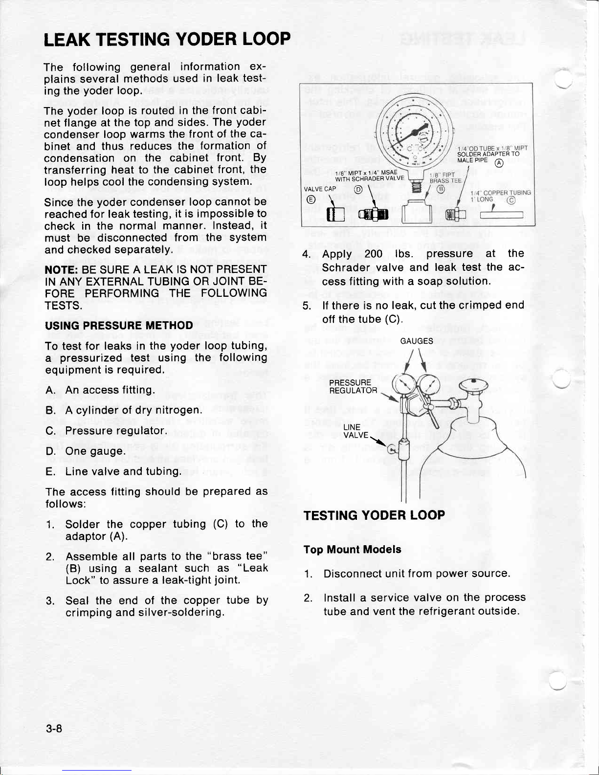
A.
An access
fitting.
B. A cylinder
of dry
nitrogen.
C. Pressure
regulator.
D. One
gauge.
E. Line valve
and tubing.
The
access
fitting should
be
prepared
as
follows:
1. Solder
the
copper tubing
(C)
to the
adaptor
(A).
2. Assemble
all
parts
to
the
"brass
tee"
(B)
using
a sealant
such
as
"Leak
Lock"
to assure a
leak-tight
joint.
3. Seal
the end of
the copper
tube bY
crimping
and silver-soldering.
SOLDER
ADAPTER
TO
N,IALE
PIPE
@
1
/8" MIPT
x
1/4"
filSAE
WITH SCHFADER
VALVE
VALVECAP
@
\
A\\
\y\\
tf
trfft
4.5.Apply
200 lbs.
pressure
at
the
Schr.ader
valve and
leak test
the ac-
cess fitting
with a soap
solution.
lf
there
is no leak,
cut the crimped
end
off
the
tube
(C).
PRESSURE
REGULATOR
LINE
VALVE
.\
TESTING
YODER
LOOP
Top Mount Models
1. Disconnect unit
f rom
power
source.
2. Install a service
valve on the
process
tube
and vent
the refrigerant
outside.
GAUGES
3-8
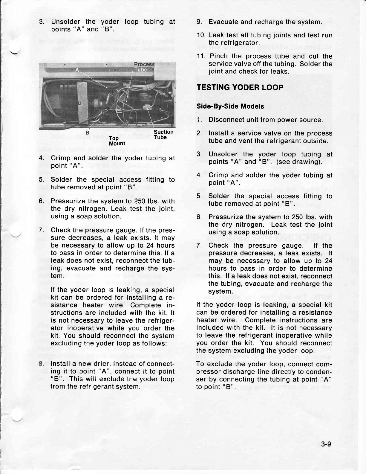
3. Unsolder
the
yoder
loop
tubing
at
points
"A"
and
"8".
Top
Mount
Crimp and solder the
yoder
tubing at
point
"A".
Solder the
special access
fitting
to
tube removed
at
point
"8".
Pressurize the
system
to
250 lbs. with
the
dry nitrogen. Leak test the
joint,
using a soap solution.
Check the
pressure
gauge.
lf the
pres-
sure decreases, a leak
exists. lt may
be necessary to
allow up to 24 hours
to
pass
in order to
determine this. lf
a
leak
does
not
exist, reconnect the tub-
ing,
evacuate and recharge
the sys-
tem.
lf the
yoder
loop is
leaking, a
special
kit can
be
ordered
for installing a re-
sistance heater wire.
Complete in-
structions are included with the
kit. lt
is
not necessary to leave
the refriger-
ator inoperative while
you
order the
kit. You should reconnect
the system
excluding the
yoder
loop as follows:
Install a new
drier. lnstead
of connect-
ing it
to
point
"A",
connect it to
point
"B".
This will
exclude the
yoder
loop
from the refrigerant
system.
9. Evacuate
and recharge the system.
10.
Leak test
all
tubing
joints
and test run
the refrigerator.
11. Pinch
the
process
tube
and cut the
service valve
off
the tubing.
Solder the
joint
and check
for leaks.
TESTING
YODER
LOOP
Side-By-Side Models
1. Disconnect
unit f rom
power
source.
2. Install
a service valve on the
process
tube
and
vent
the refrigerant
outside.
3. Unsolder the
yoder
loop tubing
at
points
"A"
and
"8".
(see
drawing).
4.
Crimp and solder the
yoder
tubing
at
point
"A".
5. Solder the special
access
fitting
to
tube
removed at
point
"8".
6.
Pressurize the
system to 250 lbs.
with
the
dry nitrogen. Leak test the
joint
using a soap
solution.
7. Check the
pressure
gauge.
lf the
pressure
decreases, a leak exists.
lt
may
be
necessary
to
allow up to 24
hours
to
pass
in
order to determine
this.
lf a leak does not
exist, reconnect
the
tubing, evacuate
and recharge the
system.
lf
the
yoder
loop is
leaking, a special
kit
can be ordered for
installing a resistance
heater wire.
Complete instructions
are
included
with the kit. lt is
not necessary
to leave the refrigerant
inoperative
while
you
order the kit. You
should reconnect
the
system
excluding the
yoder
loop.
To
exclude the
yoder
loop,
connect com-
pressor
discharge
line directly to
conden-
ser by connecting the tubing
at
point
"A"
to
point
"8",
Suction
Tube
4.
5.
6.
7.
3-9
8.
lnstall
a new drier.
9.
Evacuate
and recharge the
system.
10. Leak test
all
tubing
joints
and test run
the refrigerator.
moved
without disturbing the refrigerant
charge.
When
using
gauges
to check
operating
pressures,
observe these
precautions.
1. Make
sure the
gauges
are
accurately
calibrated.
When not
connected into a
system, the
gauge pointers
should in-
dicate
0
pressure.
lf necessary,
turn
the recalibrating
screw on the
dial un-
til the
pointer
is
at 0.
a. HIGH
SIDE - near
normal
pressure
LOW
SIDE
-
lower
pressure
(pos-
sible vacuum)
WATTAGE
-
lower
than normal
The
evaporator
tube
or other low side
tubing
is
probably
restricted
(kinked
or
blocked with foreign
particle).
This
condition is
usually accompanied
with
a
frost
build-up
on the low
side of the
restriction,
and high
side
pressures
will
not unload
and balance with the
low
side within
the
prescribed
7 to
10
minutes
after the
compressor is
stopped.
b,
HIGH SIDE - lower
pressure
LOW SIDE
-
slightly lower
pressure
WATTAGE
-
lower
than normal
These results
usually
indicate a leak
in the high
side of
the
system. Both
gauges
will
show
progressively
less
pressure
as more refrigerant
escapes.
c. HIGH
SIDE - much higher
pressure
LOW
SIDE - slightly lower
pressure
WATTAGE
-
higher
than normal
These
gauge
readings
usually
indicate
a
leak
in the low
side
of
the
system.
High
side
pressures
will
continually
increase
since air
drawn in through
the
leak collects
and becomes trapped
in
the high
side tubing. The
low side
gauge
may
show a
slight
pressure
be-
cause
of the
air being drawn in
through
the leak.
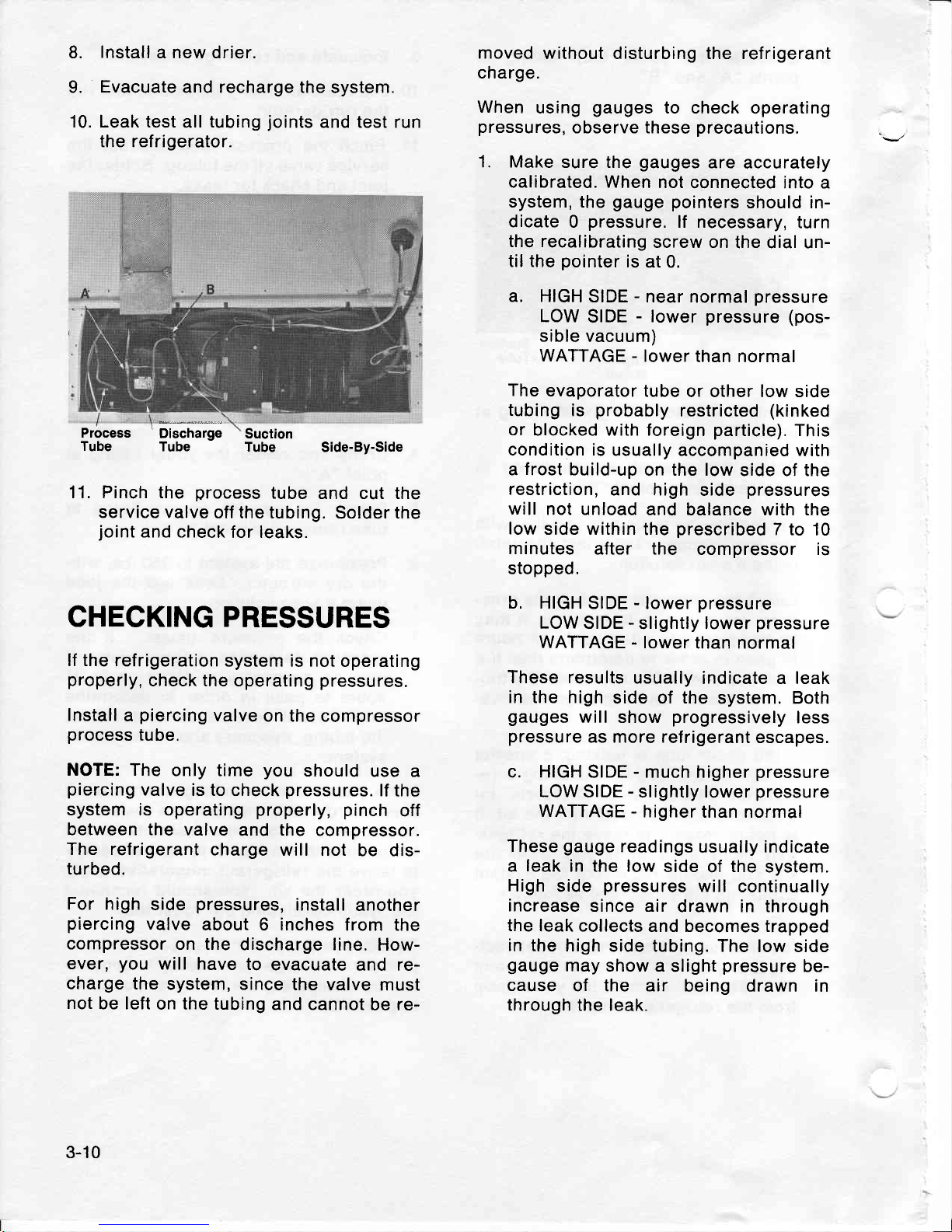
Process
Tube
Discharge
Tube
Side-By-Side
Suction
Tube
11. Pinch the
process
tube and cut the
service valve
off the
tubing.
Solder
the
joint
and check
for leaks.
CHECKING PRESSURES
lf the
refrigeration
system is not
operating
properly,
check the operating
pressures.
Install
a
piercing
valve
on the compressor
process
tube.
NOTE: The
only time
you
should
use a
piercing
valve
is to
check
pressures.
lf
the
system is
operating
properly, pinch
off
between the valve
and
the
compressor.
The refrigerant
charge
will not
be dis-
turbed.
For high
side
pressures,
install
another
piercing
valve
about 6 inches
from the
compressor
on the
discharge line.
How-
ever,
you
will have
to
evacuate
and re-
charge the
system,
since the valve
must
not
be left
on the tubing
and cannot
be re-
3-10
 Loading...