

Page 1
INSTALLATION INSTRUCTIONS
AUTOMATIC DRYER
PLEASE READ ALL INSTALLATION
INSTRUCTIONS AND REQUIREMENTS
BEFORE INSTALLING
A WARNING
FOR YOUR SAFETY
Do not store or use gasoline or other
flammable vapors or liquids in the
vicinity of this or any other appliance.
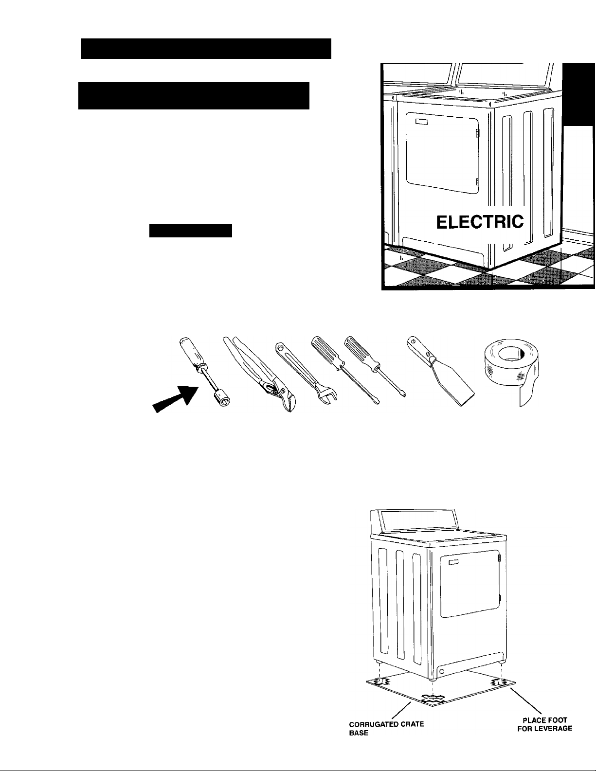
-TOOLS REQUIRED-
V DEEP WELL DRIVER
V;’ DRIVER
INSTALLING YOUR NEW DRYER
FOR YOUR SAFETY AND THE PROPER OPERA
TION OF YOUR NEW DRYER, THE DRYER
MUST BE INSTALLED IN ACCORDANCE WITH
ALL THE INSTALLATION REQUIREMENTS.
CHANNEL LOCK PLIERS
OR ADJUSTABLE WRENCH
All literature should be removed from inside dryer and
saved for future reference.
NOTE; DO NOT RAISE OR LOWER THE DRYER BY
THE BACKGUARD.
1. To remove the corrugated crate base, place your
foot on the base close to a leveling foot. Pushing
down firmly with your foot, tilt the dryer away from
you.
2. Repeat process with all leveling feet (4). Remove
excess base by hand.
SCREWDRIVER
(BLADE & TORX)
PUTTY KNIFE DUCT TAPE
BACKGUARD
P/N 53-3442
Page 2
INSTALLATION REQUIREMENTS
PLe/^SE read All Installation Instructions and Requirements Before Installing Power Cord.
rr IS RECOMMENDED THAT A QUALIRED ELECTRI
CIAN OR SERVICETECHNICIAN INSTALL YOUR DRYER.
LOCATION
This clothes dryer is designed so that it can be
installed in most locations in the home. The dryer may
even be installed in an unheated indoor location, such
as a utility room or building. However, with models hav
ing automatic dry cycles, the TIME DRY SETTING
SHOULD BE USED WHEN THE ROOM TEMPERA
TURE DROPS BELOW 50 DEGREES FAHRENHEIT
OR (10 DEGREES C.), AS THE AUTOMATIC CYCLE
MAY NOT SHUT OFF.
DO NOT INSTALL THE DRYER ON A CARPETED FLOOR.
DO NOT INSTALL OR STORE THE DRYER WHERE
IT MAY BE EXPOSED TO THE WEATHER OR DRIP
PING WATER. IF IT IS EVER EXPOSED TO WATER,
HAVE A QUALIFIED TECHNICIAN CHECK IT
BEFORE USING.
THE INSTALLATION MUST BE MADE WITH ADEQUATE CLEARANCE TO PERMIT SERVICING.
In ordinary installations enough air will be available for prop
er operation of the dryer. However, if the dryer is installed in
a mobile home, a closet or a tightly sealed room, provisions
should be made for at least 18 square inches of ventilation
area. Air openings measuring a minimum 3 in. by 3 in. should
be provided at the top and bottom of the closet door.
Ordinarily, louvered doors will satisfy the ventilation require
ments. Dryers installed in a bedroom, bathroom , or closet
must be exhausted outdoors.
Dryers installed in manufactured (mobile) homes must be
connected with 4 conductor type 3RD or SRDT cord to a 3
pole, 4 wire grounding type receptacle; by metal-clad cable;
or suitable conductors enclosed in flexible metal conduit. If
using metal-clad cable or flexible conduit, leave at least 3
feet tree to permit moving the dryer.
Where permitted by local codes, a flexible power cord (pig
tail) may be connected to the dryer. A receptacle should be
installed in a separate circuit connected to the main service
entrance panel for this type of installation. See Figure #3.
Use only a 3 or 4 wire power cord kit, including strain relief,
listed by U L for use with dryers. The power cord must have
a rating of 30 amperes, 120/240 volts AC minimum and be
terminated in closed loop or open spade lugs with upturned
ends. The attachment plug of the power cord and the recep
tacle to which it will be connected must have a minimum cur
rent rating of 30 amps and have matching configurations.
Typical 30 ampere configurations are illustrated in figure #3.
GROUNDING INSTRUCTIONS
This appliance MUST BE CONNECTED TO A GROUNDED
METAL PERMANENT WIRING SYSTEM; or an equipment
grounding conductor must be run with the circuit conductors
and connected to the equipment-grounding terminal or lead
on the appliance.
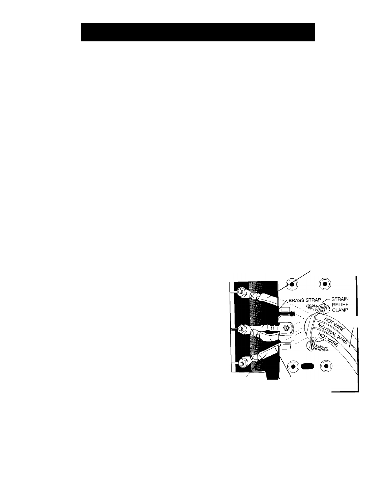
CONNECTING THE DRYER
FIG.#1 -3WIRE
LINE 1
(BLACK)
HOTWIRE ROUTED
ABOVE BRASS STRAP
1
ELECTRICAL REQUIREMENTS
This phase of the installation should be done by a qualified
service technician or electrician in accordance with the
National Electrical Code and all local codes and ordinances.
A separate circuit must be provided from the main service
entrance panel {fuse box) to the dryer. The circuit must be a 3
or 4 wire, 120/240 volt, 60 Hz, single phase, AC circuit. Each
of the 120 volt line wires (line 1 and 2) of this circuit must be
protected by 30 ampere time delay fuses or circuit breakers.
Do not fuse the neutral line or the ground line (if provided).
All wires (including neutral and ground if provided) of the
dryer circuit must be No. 10 gauge copper wire for up to 40
ft lengths and No. 8 gauge copper wire for up to 60 ft
lengths. NEVER USE A TWO WIRE CABLE WITH AN
UNINSULATED GROUND WIRE TO CONNECT THE
DRYER.
The National Electric Code requires that a means to discon
nect all ungrounded conductors (line 1 and line 2) to the
dryer be provided for service. If a power cord and receptacle
are provided this requirement is met. It other means are
used a suitable switch or circuit breaker must be installed
within sight of the dryer.
POWER
NEUTRAL
(WHITE)
LINE 2
(RED)
HOTWIRE ROUTED
BELOW BRASS STRAP
NEUTRAL WIRE
ROUTED BELOW
BRASS STRAP
THE NATIONAL ELECTRICAL CODE AND ALL
LOCAL CODES AND ORDINANCES MUST BE
OBSERVED WHEN CONNECTING THIS DRYER.
1. To gain access to the terminal block, remove the supply
cord cover plate attached to the rear of the dryer.
2. Install a suitable strain relief clamp or connector in the
strain relief hole located adjacent to the terminal block.
CORD
Page 3

3, Route the power cord (pigtail) or cable conductors through
the strain relief clamp.
FIG. #2-4 WIRE
TERMINAL BLOCK
A CAUTION - The conductors should not extend into
the dryer more than necessary to make the electrical
connections-
4. Refer to the Typical Electrical connections listed below
and make the electrical connections as instructed. We
recommend that a qualified service technician or electri
cian be consulted before connecting the dryer.
NOTE; DO NOT REMOVE THE INTERNAL GROUND WIRE
OR BRASS STRAP EXCEPT WHERE INSTRUCTED AND
REQUIRED BY LOCAL CODES AND ORDINANCES OF
YOUR AREA.
5. Check to be certain all conductors are correctly installed.
Then securely tighten all terminal nuts and the ground
screw.
6. Tighten the strain relief clamp.
7. Replace the supply cord cover plate.
8. Complete the dryer installation.
TYPICAL ELECTRICAL CONNECTIONS
LINE 1
(BLACK)
NEUTRAL
(WHITE)
LINE 2
(RED)
GREEN
GROUND WIRE
GROUND
SCREW
3-WIRE SYSTEM WITH GROUNDED NEUTRAL -
Connect power cord conductors to the line 1, neutral,
and line 2 terminals of the terminal block as shown in
Figure #1.
NOTE: Some 3-wire flat type power cords are not color
coded. When using this type of power cord, connect the
center conductor to the Neutral, connect one of the out
side conductors to line 1, and connect the other outside
conductor to line 2.
3-WIRE SYSTEM WITH GROUNDED METAL CLAD
CABLE OR RIGID METAL CONDUIT - Remove the
internal green ground wire or brass strap from the
Neutral terminal and the ground screw. Connect the
power cable conductors to the line 1, Neutral, and line
2 terminals as shown in Figure #2.
NOTE: An approved grounding type strain relief clamp
or conduit connector must be installed for this type of
installation.
4-WIRE SYSTEM - Remove internal green ground wire
or brass strap from the Neutral terminal and the ground
screw. Connect the power cord green grounding con
ductor to the ground screw. Connect the remaining
power cord conductors to the line 1, Neutral, and line 2
terminals as shown in Figure #2.
A BEFORE OPERATING YOUR DRYER READ
ALL SAFETY PRECAUTIONS LISTED IN THE
OPERATING INSTRUCTIONS.
Page 4

2. STABILITY
Place dryer in the location where it will
be used. Check, by rocking dryer with
hands on opposite corners, that all
four (4) feet are in firm contact with the
floor. If it rocks, adjust as needed.
3A. OUTSIDE WALL
VENT HOOD
OUTSIDE WALL
Attach dryer vent pipe to outside
exhaust vent. Outside exhaust vent
should fit over dryer vent pipe to avoid
catching lint. Tape all joints with heat
duct tape.
3D. INDOOR EXHAUSTING
(NOT RECOMMENDED unless
conditions on page 6 are met.)
3B. BASEMENT WALL
BASEMENT WINDOW,
90° ELBOW 4” DIA—
BASEMENT
WALL
In basements, the exhaust can be ele
vated by installing elbows to raise the
vent hood above the ground level.
4. ELECTRICAL CONNECTION
3C. FLOOR EXHAUSTING
If space permits, a 4” dia. elbow point
ed downward through the floor may be
used. If not possible, the dryer may be
exhausted through the bottom as illus
trated later in this manual.
INSTALLATION WITH
POWER CORD (PIGTAIL).
When exhausting indoors, use the
indoor exhaust kit and maintain a mini
mum clearance of 6 inches between the
rear of the dryer and any adjacent wall.
Read further instructions in this manual.
Page 6.____________________________
FLEXIBLE
POWER CORD
Ó
WALL
RECEPTACLE
MAIN SERVICE
ENTRANCE PANEL
This appliance must be connected to a grounded metal, permanent wiring
system; or an equipment - grounding conductor must be run with the cir
cuit conductors and connected to the equipment - grounding terminal or
lead on the appliance.
Page 5

EXHAUST VENTING REQUIREMENTS
A WARNING
FIRE HAZARD
NEVER EXHAUST INTO A CHIMNEY, DUCT, GAS
VENT, WALL, CEILING, ATTIC, CONFINED SPACE,
BEDROOM, OR UNDER A BUILDING.
DO NOT USE VINYL, PLASTIC, CLOTH OR OTHER
NONMETALIC DUCT TO EXHAUST THE DRYER.
MULTIPLE INSTALLATIONS REQUIRE INDIVIDUAL
EXHAUST SYSTEMS.
DRYERS INSTALLED IN A MANUFACTURED
(MOBILE) HOME MUST BE VENTED OUTDOORS.
PERIODICALLY CLEAN LINT FROM VENT SYSTEM.
CLEAN FREQUENTLY IF USING MAXIMUM
LENGTH OF VENT.
Exhausting can be accomplished directly from the rear of
the cabinet, through right side of the cabinet, or down
ward through the cabinet base. If your existing ductwork is
plastic, nonmetal, or combustible, replace it with METAL.
Standard four inch diameter galvanized or aluminum pipe
should be used. DO NOT use any pipe which may be sus
ceptible to rust or COMBUSTION. To avoid catching lint
the crimped end of each pipe section should face away
from the dryer. Do not use screws or other fasteners that
extend into the exhaust pipe or duct.
Number of
90° Turns
Separated by
at least 4 ft.
of Straight Run
0
f
2
■ \ .. ^
-----
VENT HOOD TYPE
— I I— 4"
OPENING
45 feet
35 feet
25 feet
____________
— I I—
OPENING
30 feet
20 feet
10 feet
K
Vent should never exceed 0.6 inches water column back
pressure, fluff empty dryer.
BOTTOM EXHAUSTING
If space permits behind the dryer, a 4” elbow pointed down
ward may be used to pass the exhaust system through the
floor. If this is not possible, the dryer may be exhausted
through the bottom as illustrated in FIG. #7. When exhaust
ing in this manner, the installation should be made accord
ing to the following steps:
1. Disconnect electric cord.
2. Raise the top of the dryer by pressing in with a putty knife
on the top panel retaining clips. FIG. #5.
Flexible 4” diameter metal tubing may be used for
exhausting the dryer. However, the convolutions create a
greater restriction than pipe and serious blockage can
result if the tubing is bent too sharply. If clearance to the
wall is less than 8 inches, use a 4” sheet metal elbow at
the rear of the dryer to avoid a sharp bend in the tubing.
Do not use over 8 feet (2.5 m.) of flexible metallic tubing
between the elbow and the vent hood.
VENT HOOD
The use of a vent hood
on the outside is recom
mended.
When the dryer stops the damper automatically closes to
prevent drafts and the entrance of insects and rodents. To
avoid restricting the outlet, maintain a minimum 8 inch
clearance between the hood and the ground or other
obstruction.
FIG. #4-
CORRECT
LENGTH OF VENT
PIPE CONNECTION
EXHAUST FLOW EXHAUST FLOW
_______________
Maximum Length of 4” Rigid Duct
INCORRECT
_______
Remove front panel by removing two VT screws inside top
corners of front panel. Disconnect door switch wires.
NOTE position of front seal before removing front panel.
Remove the cylinder as follows:
a. Force idler pulley to the right and remove cylinder belt
from idler and motor pulleys. See FIG. #6.
b. Lift up and turn cylinder to clear the roller supports.
c. Lift out of cabinet.
5. Remove tape and screw securing dryer vent pipe.
6. Remove the 4” dryer vent pipe and shorten to a suitable
length. Length depends on type of elbow purchased.
7. Remove knockout from dryer base.
8. Place dryer in position and mark duct location on floor.
Check floor joist location before sawing hole in floor.
Page 6

9. Saw a AT hole in floor and position dryer.
10. Secure the shortened pipe to the blower housing with a
screw at the top and seal all joints with tape or silicone
bathtub caulk.
11. install a 4” 90 degree elbow as shown.
When exhausting from the side, the installation should be
made according to the steps described in BOTTOM
EXHAUSTING and as noted above.
INDOOR EXHAUSTING
Step #3D shows a typical installation with indoor exhausting.
Indoor exhausting is not recommended unless the laundry
room is large and sufficient cross ventilation is available by
opening two windows, or a door and a window, or where an
exhaust fan is located in the laundry room.
When exhausting indoors, use the Indoor Exhausting Kit and
maintain a minimum clearance of 6 inches between the rear
of the dryer and any adjacent wall. The indoor Exhausting Kit
is available from your dealer under Part No. 53-0298.
SPECIAL REQUIREMENTS FOR MANUFACTURED
(MOBILE) HOME INSTALLATIONS
12. Seal rear opening of cabinet with the cover plate provid
ed with your dryer. Located with literature. Attach cover
plate to rear of the cabinet with #8 sheet metal screws
or duct tape. (Not supplied)
13. Place cylinder belt around cylinder with grooved side
toward cylinder. FIG. #6.
14. Reinstall cylinder by pushing and turning until rollers are
snapped in cylinder grooves and cylinder turns freely.
15. Position cylinder belt with grooved side around motor
pulley. Pull idler pulley right until smooth side of belt can
be routed around left side of idler pulley. FIG. #6.
16. Rotate cylinder counter-clockwise to position belt..
17. Replace dryer front and reconnect door switch wires.
Make sure the front seal is in the original position.
18. Complete exhaust system to outdoors.
SIDE EXHAUSTING
Figure #8 illustrates side exhaust venting pipe connections
inside the dryer cabinet. When venting the dryer from the
side, the cabinet knockout must be removed. A 4” metal
exhaust pipe must be purchased. The rear exhaust pipe
inside the dryer must then be shortened. (Length will depend
on type of elbow purchased.) Secure the shortened pipe to
the Blower Housing with a screw at the top, attach elbow and
metal exhaust pipe, and seal all joints with tape or silicone
bathtub caulk.
Follow steps outlined for installation with these exceptions:
When installed in a manufactured (mobile) home.
1. THE DRYER INSTALLATION must conform to the
Manufactured Home Construction and Safety, Title 24,
HUD (Part 280, 1975).
2. THE DRYER must be attached to the manufactured
(mobile) home structure as follows:
a. Dismantle the dryer as described in bottom exhaust
ing.
b. Buy two #10 1 'k" round head wood screws. Drive them
through the attachment screw holes of the base into
the floor. See FIG. #8 for location.
c. Reassemble the dryer.
2. THE EXHAUST DUCT must be exhausted to the outside
using metal ducting. It should not terminate beneath the
manufactured (mobile) home.
3. THE VENT HOOD must be securely fastened to the
manufactured (mobile) home structure.
THIS DRYER IS NOT SUITABLE FOR USE IN RECRE
ATION VEHICLES SUCH AS TRAVEL TRAILERS,
CAMPERS, OR MOTOR HOMES.
FINAL CHECK OUT
1. Plug dryer in.
2. Following your operating instructions, operate the
dryer briefly on all control settings. A slight odor
may be noticed with a new machine.
3. Allow empty dryer to operate on highest heat
setting for a few minutes.
4. Stop dryer and wipe inside of cylinder with a clean
cloth.
5. Wipe fingerprints and dirt from outside of dryer with
soft cloth.
6. A protective plastic film may cover the control
panel, this should be removed.
 Loading...