

Page 1
MATROX PULSAR
1
CAMERA INTERFACE APPLICATION NOTE
REDLAKE MASD (KODAK) 1.6i JUNE 19, 2001
Basics about the
camera
Mode of operations as
per Matrox Imaging (in
parentheses as per
camera manufacturer)
Basics about the
interface modes
Camera Descriptions
§ 1534 × 1024 × 10-bit @ 5 fps (maximum).
§ Single channel RS-422 digital video output.
§ Progressive scan.
§ External sync.
§ Internal or external exposure control.
§ 10 MHz pixel clock rate.
Interface Modes
§ Pseudo-continuous
§ Asynchronous reset (Trigger, Control)
Camera Interface Briefs
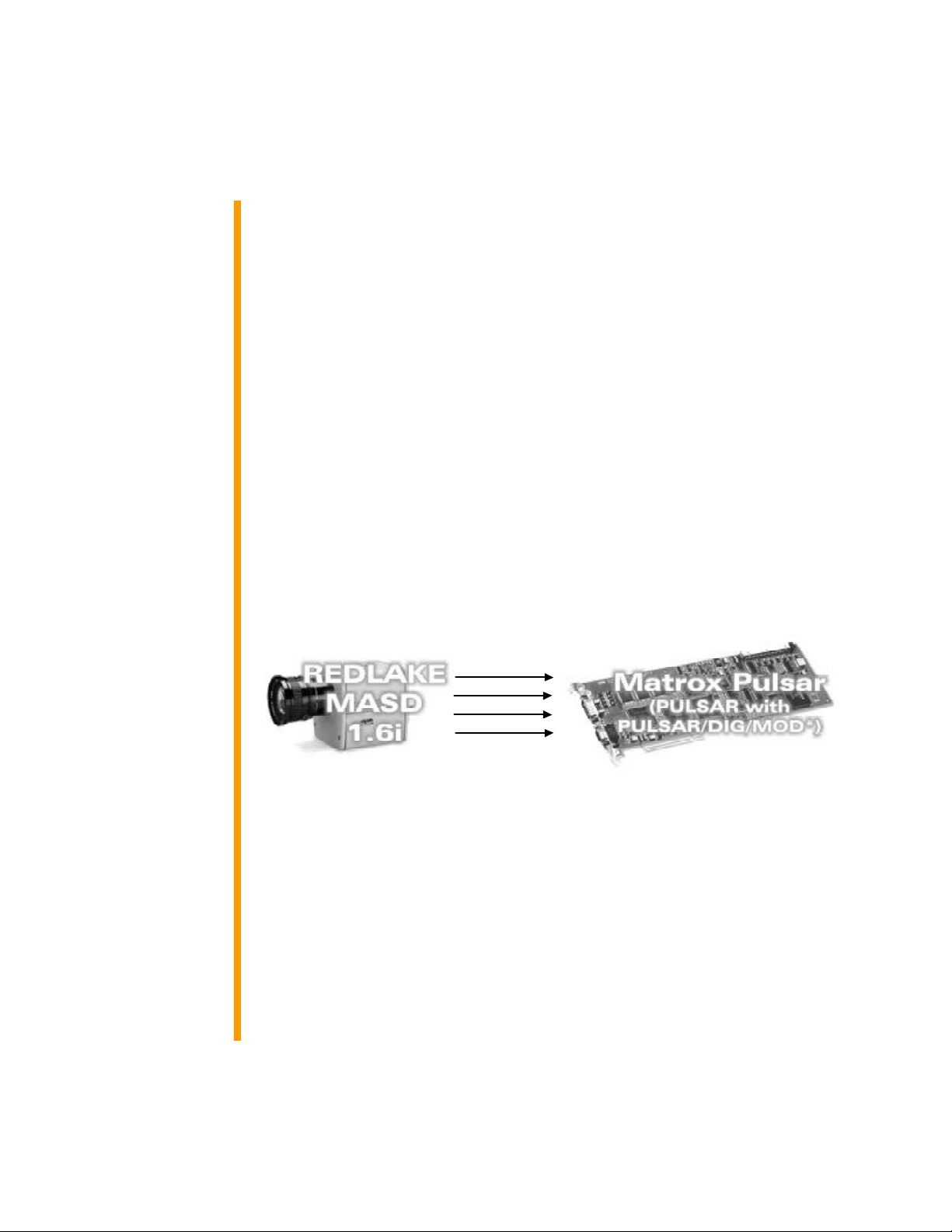
Mode 1: Pseudo-continuous
§ 1534 × 1024 × 10-bit @ 5 fps (maximum).
§ Single channel RS-422 digital video.
§ Progressive scan.
§ Matrox Pulsar receiving HSYNC (LINE ENABLE), VSYNC (FRAME
ENABLE), PIXEL CLOCK (PIX DATA @ 10 MHz) and video from camera.
§ DCF used: KOD16D.DCF
VIDEO
LINE EN.
FRAME EN.
PIX DATA
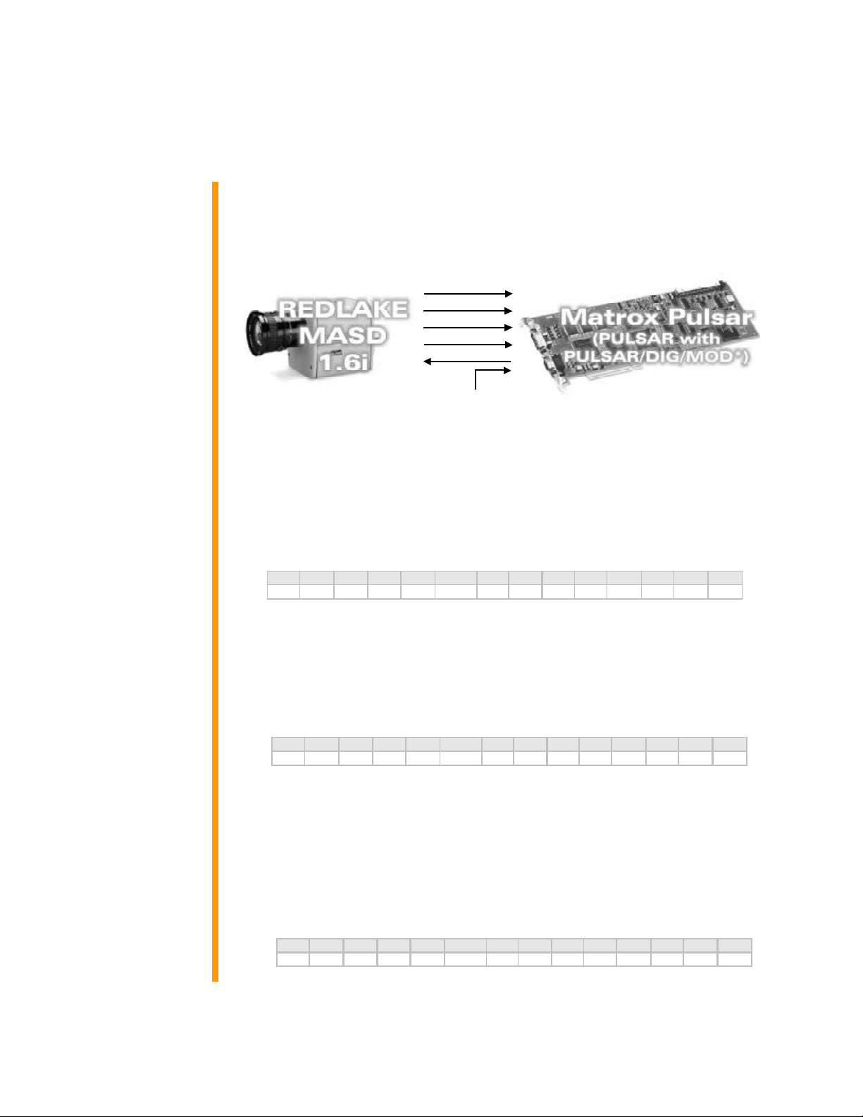
Mode 2: Asynchronous Reset (Trigger, Control)
§ 1534 × 1024 × 10-bit.
§ Single channel RS-422 digital video.
§ Progressive scan.
§ Matrox Pulsar receiving TTL external trigger signal.
§ Matrox Pulsar sending EXPOSURE1 (EXPOSE) signal to camera to
initiate and control exposure time.
§ Matrox Pulsar receiving HSYNC (LINE ENABLE), VSYNC (FRAME
ENABLE), PIXEL CLOCK (PIX DATA @ 10 MHz) and video signals from
camera.
Continued…
*Matrox Pulsar RS-422 digital data input board
PUL-CID-047
Page 2
MATROX PULSAR
2
CAMERA INTERFACE APPLICATION NOTE
REDLAKE MASD (KODAK) 1.6i JUNE 19, 2001
Basics about the
interface modes
Camera Interface Briefs (Cont.)
Mode 2: Asynchronous Reset (Trigger, Control)
§ DCF used: KOD16TD.DCF (Trigger)
§ DCF used: KOD16AE.DCF (Control)
VIDEO
LINE EN.
FRAME EN.
PIX DATA
EXPOSE
Specifics about
the interface modes
TTL EXTERNAL TRIGGER
*Matrox Pulsar RS-422 digital data input board
Camera Interface Details
Mode 1: Pseudo-continuous
§ Frame Rate: Matrox Pulsar receives the continuous video from the
camera at 10 frames per second.
§ Exposure time: Exposure time is controlled by the Remote Panel
software. Refer to the camera manual for more information.
§ Remote Panel software settings: Settings for this mode are as follows:
DEF GAB BKB BKE MDE EXE STP TRM TRS TRE RDM TPD TPW DGN
on -22 0 0 PI 15.096 P P AIA 1 1 255 5 2
Mode 2: Asynchronous Reset (Trigger)
§ Frame rate: The frame rate is determined by the frequency of the
external trigger signal.
§ Exposure time: Exposure time is controlled by the Remote Panel
software. Refer to the camera manual for more information.
§ Remote Panel software settings: Settings for this mode are as follows:
DEF GAB BKB BKE MDE EXE STP TRM TRS TRE RDM TPD TPW DGN
on -22 0 0 TR 15.096 P P AIA 1 1 255 5 2
Mode 2: Asynchronous Reset (Control)
§ Frame rate: The frame rate is determined by the frequency of the
external trigger signal.
§ Exposure time: The width (rising to falling edge) of the EXPOSURE1
(EXPOSE) signal initiates and controls the exposure. The exposure time
can be modified in the DCF using Matrox Intellicam or with the MIL
MdigControl() function. Consult the manual for more information.
§ Remote Panel software settings: Settings for this mode are as follows:
DEF GAB BKB BKE MDE EXE STP TRM TRS TRE RDM TPD TPW DGN
on -22 0 0 CD 15.096 P P AIA 1 1 255 5 2
PUL-CID-047
Page 3

MATROX PULSAR
3
CAMERA INTERFACE APPLICATION NOTE
REDLAKE MASD (KODAK) 1.6i JUNE 19, 2001
Cabling details for this
interface mode
Pin name Pin no.
* Connection not necessary for this mode however allows this cable to be used for both modes.
Cabling Requirements
Mode 1: Pseudo-continuous
§ Cable: DBHD68-TO-OPEN (open ended) cable required for video,
synchronization and control signals.
§ Connection: Connections between the 68-pin connector of the camera
and the 68-pin connectors of the Matrox Pulsar are as follows:
PULSAR/DIG/MOD
(68-pin connector)
DATA9+ 08 ← MSB+ 02
DATA9- 42 ← MSB- 36
DATA8+ 09 ← MSB-1+ 03
DATA8- 43 ← MSB-1- 37
DATA7+ 10 ← MSB-2+ 04
DATA7- 44 ← MSB-2- 38
DATA6+ 11 ← MSB-3+ 05
DATA6- 45 ← MSB-3- 39
DATA5+ 13 ← MSB-4+ 06
DATA5- 47 ← MSB-4- 40
DATA4+ 14 ← MSB-5+ 07
DATA4- 48 ← MSB-5- 41
DATA3+ 15 ← MSB-6+ 08
DATA3- 49 ← MSB-6- 42
DATA2+ 16 ← MSB-7+ 09
DATA2- 50 ← MSB-7- 43
DATA1+ 19 ← MSB-8+ 10
DATA1- 53 ← MSB-8- 44
DATA0+ 20 ← MSB-9+ 11
DATA0- 54 ← MSB-9- 45
CLKIN+ 29 ← PIX DATA STRB+ 29
CLKIN- 63 ← PIX DATA STRB- 63
HSYNC+ 26
HSYNC- 60 ← LINE ENA- 60
VSYNC+ 25 ← FRME ENA+ 25
VSYNC- 59 ← FRME ENA- 59
EXPOSURE1+ 30* → EXPOSE+ 30*
EXPOSURE1- 64* → EXPOSE- 64*
TTL_USR0 31 → MC0 31
TTL_USR1 32 → MC1 32
TTL_USR2 33 → MC2 33
GROUND 1 -- GROUND 01
GROUND 12 -- GROUND 12
Continued…
←
REDLAKE MASD 1.6i
(68-pin connector)
Pin name Pin no.
LINE ENA+ 26
PUL-CID-047
Page 4

MATROX PULSAR
CAMERA INTERFACE APPLICATION NOTE
REDLAKE MASD (KODAK) 1.6i JUNE 19, 2001
Cabling details for this
interface mode
Pin name Pin no.
Cabling Requirements(Continued)
Mode 1: Pseudo-continuous
PULSAR/DIG/MOD
(68-pin connector)
GROUND 34 -- GROUND 34
GROUND 35 -- GROUND 35
GROUND 46 -- GROUND 46
GROUND 68 -- GROUND 68
Mode 2: Asynchronous Reset (Trigger, Control)
§ Cable: IMG-7W2-TO-5BNC and DBHD100-TO-OPEN (open ended)
cables required for video, synchronization and control signals.
§ External Trigger: TTL external trigger source should be connected to the
TTL trigger input of IMG-7W2-TO-5BNC cable.
§ Connection: All connections are as in Mode 1: Pseudo-continuous.
REDLAKE MASD 1.6i
(68-pin connector)
Pin name Pin no.
The DCF(s) mentioned in this application note can be found on the MIL or our FTP site (ftp.matrox.com). The information furnished by Matrox
Electronics System, Ltd. is believed to be accurate and reliable. Please verify all interface connections with camera documentation or manual. Contact
your local sales representative or Matrox Sales office or Matrox Imaging Applications at 514-822-6061 for assistance.
Corporate headquarters:
Canada and U.S.A.
Matrox Electronic Systems Ltd.
1055 St. Regis Blvd.
Dorval, Quebec H9P 2T4
Canada
Tel: (514) 685-2630
Fax: (514) 822-6273
PUL-CID-047
 Loading...